Embed Size (px)
Citation preview
e-ISSN: 2582-5208 International Research Journal of Modernization in Engineering Technology and Science
( Peer-Reviewed, Open Access, Fully Refereed International Journal )
Volume:03/Issue:12/December-2021 Impact Factor- 6.752 www.irjmets.com
www.irjmets.com @International Research Journal of Modernization in Engineering, Technology and Science
[1]
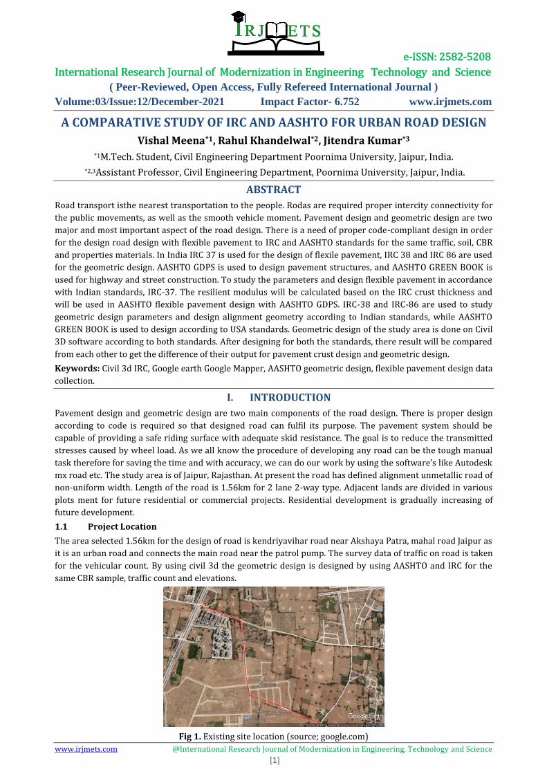
A COMPARATIVE STUDY OF IRC AND AASHTO FOR URBAN ROAD DESIGN
Vishal Meena*1, Rahul Khandelwal*2, Jitendra Kumar*3 *1M.Tech. Student, Civil Engineering Department Poornima University, Jaipur, India.
*2,3Assistant Professor, Civil Engineering Department, Poornima University, Jaipur, India.
ABSTRACT
Road transport isthe nearest transportation to the people. Rodas are required proper intercity connectivity for
the public movements, as well as the smooth vehicle moment. Pavement design and geometric design are two
major and most important aspect of the road design. There is a need of proper code-compliant design in order
for the design road design with flexible pavement to IRC and AASHTO standards for the same traffic, soil, CBR
and properties materials. In India IRC 37 is used for the design of flexile pavement, IRC 38 and IRC 86 are used
for the geometric design. AASHTO GDPS is used to design pavement structures, and AASHTO GREEN BOOK is
used for highway and street construction. To study the parameters and design flexible pavement in accordance
with Indian standards, IRC-37. The resilient modulus will be calculated based on the IRC crust thickness and
will be used in AASHTO flexible pavement design with AASHTO GDPS. IRC-38 and IRC-86 are used to study
geometric design parameters and design alignment geometry according to Indian standards, while AASHTO
GREEN BOOK is used to design according to USA standards. Geometric design of the study area is done on Civil
3D software according to both standards. After designing for both the standards, there result will be compared
from each other to get the difference of their output for pavement crust design and geometric design.
Keywords: Civil 3d IRC, Google earth Google Mapper, AASHTO geometric design, flexible pavement design data
collection.
I. INTRODUCTION
Pavement design and geometric design are two main components of the road design. There is proper design
according to code is required so that designed road can fulfil its purpose. The pavement system should be
capable of providing a safe riding surface with adequate skid resistance. The goal is to reduce the transmitted
stresses caused by wheel load. As we all know the procedure of developing any road can be the tough manual
task therefore for saving the time and with accuracy, we can do our work by using the software’s like Autodesk
mx road etc. The study area is of Jaipur, Rajasthan. At present the road has defined alignment unmetallic road of
non-uniform width. Length of the road is 1.56km for 2 lane 2-way type. Adjacent lands are divided in various
plots ment for future residential or commercial projects. Residential development is gradually increasing of
future development.
1.1 Project Location
The area selected 1.56km for the design of road is kendriyavihar road near Akshaya Patra, mahal road Jaipur as
it is an urban road and connects the main road near the patrol pump. The survey data of traffic on road is taken
for the vehicular count. By using civil 3d the geometric design is designed by using AASHTO and IRC for the
same CBR sample, traffic count and elevations.
Fig 1. Existing site location (source; google.com)
e-ISSN: 2582-5208 International Research Journal of Modernization in Engineering Technology and Science
( Peer-Reviewed, Open Access, Fully Refereed International Journal )
Volume:03/Issue:12/December-2021 Impact Factor- 6.752 www.irjmets.com
www.irjmets.com @International Research Journal of Modernization in Engineering, Technology and Science
[2]
1.2 Civil 3D
AutoCAD is a commercial computer aided (cad) and drafting software application. Developed and marketed by
Autodesk in December 1982 as a desktop app running on microcomputers with internal graphic controllers.
AutoCAD is used in industry, by architects, project managers, engineers, graphic designers, city planners and
other professional. It was supported by 750 training centres in 1994.
1.3 Global Mapper
Global Mapper is a geographic information system (GIS) software package currently developed by Blue Marble
Geographics [1] that runs on Microsoft Windows. The GIS software competes with ESRI, GeoMedia, Manifold
System, and MapInfo GIS products. Global Mapper handles both vector, raster, and elevation data, and provides
viewing, conversion, and other general GIS features.[2] Global Mapper has an active user community with a
mailing list and online forums.[3]
1.4 Google Earth
Google Earth is a computer program, formerly known as Keyhole Earth Viewer, that renders a 3D
representation of Earth based primarily on satellite imagery. The program maps the Earth by superimposing
satellite images, aerial photography, and GIS data onto a 3D globe, allowing users to see cities and landscapes
from various angles. Users can explore the globe by entering addresses and coordinates, or by using a keyboard
or mouse. Google Earth is able to show various kinds of images overlaid on the surface of the earth and is also a
Web Map Service client. Recently Google has revealed that Google Earth now covers more than 98 percent of
the world and has captured 10 million miles of Street View imagery, a distance that could circle the globe more
than 400 times.
1.5 Objective of the study
To evolve the flexible pavement design from AASHTO and IRC compare the parameters, procedure and
output of the crust thickness.
To evolve geometric design of road from AASHTO and IRC using civil 3d and compare their parameters and
output of the road design
The study for evolving flexible pavement design of a road project has been undertaken using AASHTO and
IRC standard codes. IRC-37, IRC-38, IRC- 86, AASHTO GDPS and AASHTO GREEN BOOK will be used.
II. METHODOLOGY
Flexible Pavement: Flexible pavements transfer wheel load stresses to the lower layers through grain-to-
grain transfer at the granular structure's points of contact. As the depth of the wheel on the floor increases, the
load is spread over a larger area and the tension decreases. Flexible pavements typically have many layers to
take advantage of this stress distribution characteristic.
Surface course - The surface course is the layer that comes into direct contact with traffic and is usually made
of high-quality materials.
Binder course - The bulk of the asphalt concrete structure is provided by this layer. Its main goal is to
distribute weight evenly across the base course. Because the binder course is made up of aggregates with less
asphalt and does not require the same level of quality as the surface course, replacing a portion of the surface
course with the binder course results in a more cost-effective design.
Base course - A layer of material in an asphalt roadway, racetrack, riding arena, or sporting field is known as
the base course or basecourse in pavements. It is found beneath the surface layer, which consists of the wearing
course and, on occasion, an additional binder course.
Sub-Base course - The layer of aggregate material laid on the subgrade on which the base course layer is
located is referred to as the subbase in highway engineering. It can be skipped if there will only be foot traffic
on the pavement, but it is required for vehicle-trafficked surfaces.
Sub-grade - The top soil, also known as the sub-grade, is a naturally occurring soil layer that has been prepared
to withstand the stresses of the layers above it. It's crucial not to put too much strain on the soil's sub-grade. It
should be compacted and wetted to the desired consistency. Factors affecting geometric design
e-ISSN: 2582-5208 International Research Journal of Modernization in Engineering Technology and Science
( Peer-Reviewed, Open Access, Fully Refereed International Journal )
Volume:03/Issue:12/December-2021 Impact Factor- 6.752 www.irjmets.com
www.irjmets.com @International Research Journal of Modernization in Engineering, Technology and Science
[3]
Design speed - The most significant factor affecting geometric design is design speed. Visibility, horizontal
curve length, and vertical curve length are all affected. All geometrical designs have a design speed because the
speed of a vehicle varies depending on the driver, terrain, and other factors.
Topography - Topography is the next major factor affecting geometric design. Roads with the required
standards for a single terrain are easier to build. However, the construction costs increase with the gradient
and terrain in multiple ways at a certain design speed.
Vehicles - The dimensions, weight of the axle and functionality of a vehicle affect design aspects such as the
pavement width, curve radii, clearances, geometry of car parks, etc. For establishing highway design controllers
to accommodate a design vehicle of the designated type, standard weight, sizes and operating characteristics
are used.
Human - The physical, mental and psychological characteristics of the driver and pedestrians such as the
reaction time are important human factors influencing geometric design.
Environmental - In the geometric design of the routes, due account should be taken of factors such as air
pollution, noise pollution, etc.
2.1 Data Collection and Analysis
For any research work, data collection is the core part of it. For the study work primary data as well as
secondary data are required. For this project to perform pavement and geometric design, data collection
consists of 3 parts: -
1. Traffic volume count.
2. Collecting northing, easting and elevation (NEZ) of the points on alignment.
3. Soil sample collection.
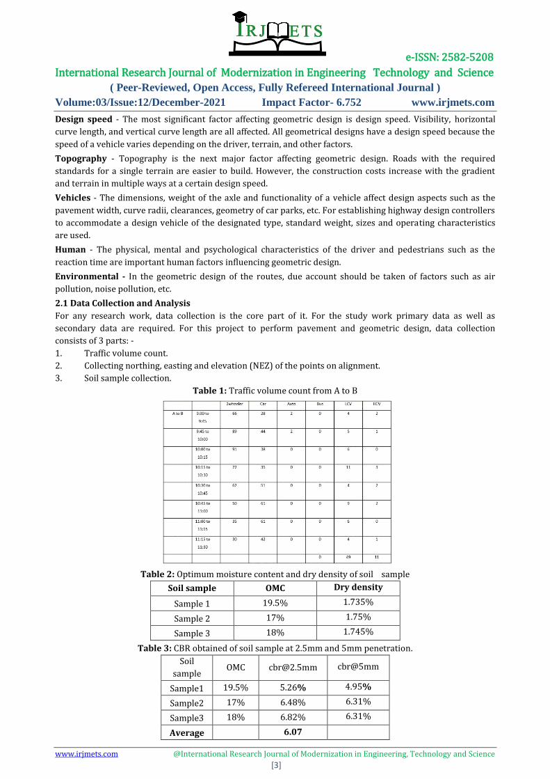
Table 1: Traffic volume count from A to B
Table 2: Optimum moisture content and dry density of soil sample
Soil sample OMC Dry density
Sample 1 19.5% 1.735%
Sample 2 17% 1.75%
Sample 3 18% 1.745%
Table 3: CBR obtained of soil sample at 2.5mm and 5mm penetration.
Soil
sample OMC [email protected] cbr@5mm
Sample1 19.5% 5.26% 4.95%
Sample2 17% 6.48% 6.31%
Sample3 18% 6.82% 6.31%
Average 6.07
e-ISSN: 2582-5208 International Research Journal of Modernization in Engineering Technology and Science
( Peer-Reviewed, Open Access, Fully Refereed International Journal )
Volume:03/Issue:12/December-2021 Impact Factor- 6.752 www.irjmets.com
www.irjmets.com @International Research Journal of Modernization in Engineering, Technology and Science
[4]
CBR is higher at 2.5mm penetration than at 5mm penetration. The average value at 2.5 penetration is 6.07. in
this project, this value will be used in the design of the flexible pavements.
IRC PAVAMENT DESIGN
The aim of pavement design is to determine the overall thickness of the pavement structure, as well as the
thickness of individual structural components, in order to bear the projected traffic load while preserving the
pavement's efficiency under the current climatic conditions. In structural design, the stresses caused by traffic
and temperature are measured, and the pavement thickness is chosen so that the developed stresses/strains
are less than the permissible values. IRC: 37 is widely used in India as a guideline for versatile pavement design.
Soil CBR
Design traffic
Design traffic in msa is calculated by: -
N= 365 × [(1 + 𝑟) ^𝑛 − 1] × 𝐴 × 𝐷 × 𝐹
R
Where
N= design period of ‘n’ year
A= initial traffic (no. of vehicles per day) in the year of construction of compilation
D = lateral distribution factor
F = vehicle damage factor (VDF)
n = design period, in years
r = annual growth rate of commercial vehicles in decimal (e.g., for 6 per cent annual growth rate, r = 0.06).
The traffic in the year of completion of construction may be estimated using: -
𝐴 = 𝑃 (1 + 𝑟) 𝑥
Where,
P = number of commercial vehicles per day as per last count.
x = number of years between the last count and the year of completion of construction.
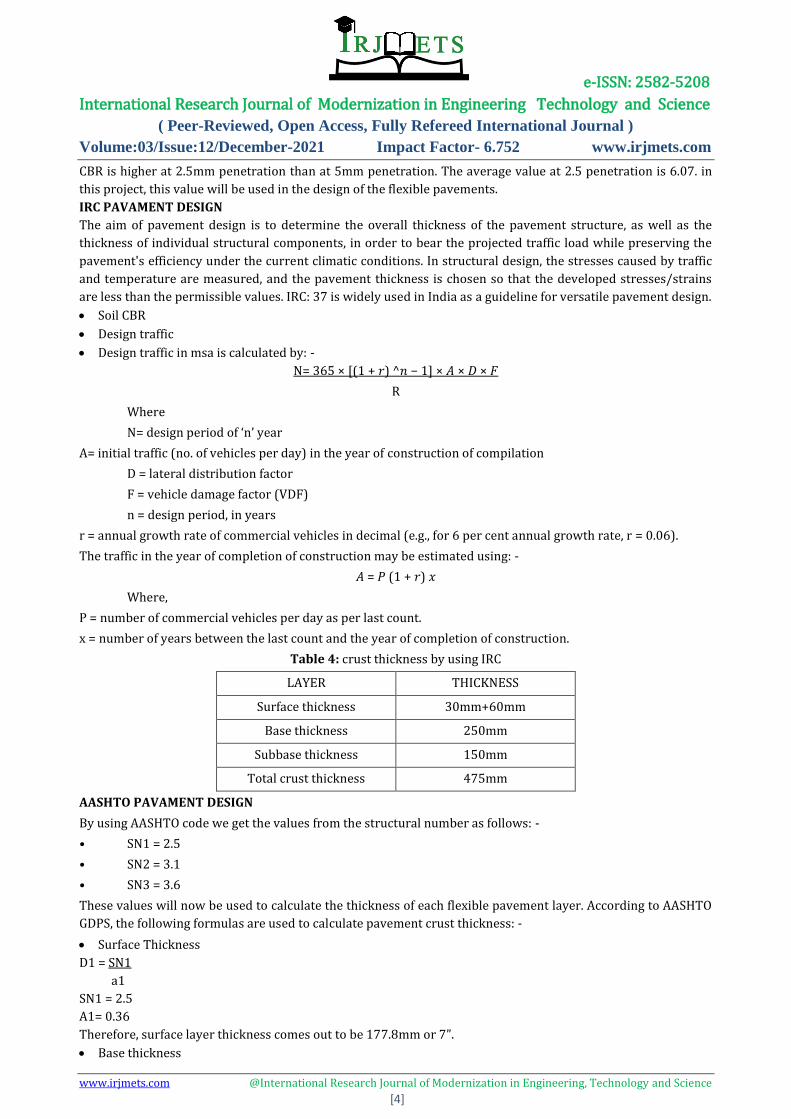
Table 4: crust thickness by using IRC
LAYER THICKNESS
Surface thickness 30mm+60mm
Base thickness 250mm
Subbase thickness 150mm
Total crust thickness 475mm
AASHTO PAVAMENT DESIGN
By using AASHTO code we get the values from the structural number as follows: -
• SN1 = 2.5
• SN2 = 3.1
• SN3 = 3.6
These values will now be used to calculate the thickness of each flexible pavement layer. According to AASHTO
GDPS, the following formulas are used to calculate pavement crust thickness: -
Surface Thickness
D1 = SN1
a1
SN1 = 2.5
A1= 0.36
Therefore, surface layer thickness comes out to be 177.8mm or 7”.
Base thickness
e-ISSN: 2582-5208 International Research Journal of Modernization in Engineering Technology and Science
( Peer-Reviewed, Open Access, Fully Refereed International Journal )
Volume:03/Issue:12/December-2021 Impact Factor- 6.752 www.irjmets.com
www.irjmets.com @International Research Journal of Modernization in Engineering, Technology and Science
[5]
D2 = SN2-a1 x D1
A2 X M2
SN2=3.1
a2=0.12
M2=0.8
Therefore, base layer thickness comes out to be 177.8mm or 7”.
Subbase Thickness
D3 = SN3 – a1 x D1 -a2 x D2 x M2
a3 x M3
SN3=3.6
a3=0.079
M3=0.8
Therefore, subbase thickness comes out to be 177.8mm or 7”.
Therefore, as per AASHTO, pavement thickness comes out to be 21” or 533.4mm.
Table 5: Crust thickness by using AASHTO
LAYER THICKNESS
SURFACE Thickness 7”or 177.8mm
Base thickness 7”or 177.8mm
Sub base thickness 7”or 177.8mm
Total crust thickness 21”or 533.4mm
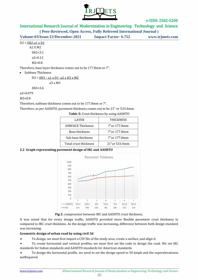
2.2 Graph representing pavement design of IRC and AASHTO
Fig 2: compression between IRC and AASHTO crust thickness.
It was noted that for every design traffic, AASHTO provided more flexible pavement crust thickness in
compared to IRC crust thickness. As the design traffic was increasing, difference between both design standard
was increasing.
Geometric design of urban road by using civil 3d
To design, we must first import a CSV file of the study area, create a surface, and align it.
To create horizontal and vertical profiles, we must first set the code to design the road. We set IRC
standards for Indian standards and AASHTO standards for American standards.
To design the horizontal profile, we need to set the design speed to 50 kmph and the superelevationis
notRequired
e-ISSN: 2582-5208 International Research Journal of Modernization in Engineering Technology and Science
( Peer-Reviewed, Open Access, Fully Refereed International Journal )
Volume:03/Issue:12/December-2021 Impact Factor- 6.752 www.irjmets.com
www.irjmets.com @International Research Journal of Modernization in Engineering, Technology and Science
[6]
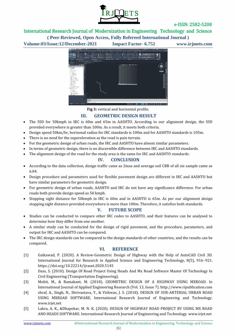
Fig 3: vertical and horizontal profile.
III. GEOMETRIC DESIGN RESULT The SSD for 50kmph in IRC is 60m and 65m in AASHTO. According to our alignment design, the SSD
provided everywhere is greater than 100m. As a result, it meets both criteria.
Design speed 50km/hr, horizonal radius for IRC standards is 100m and for AASHTO standards is 105m.
There is no need for the superelevation as the road is pain terrain.
For the geometric design of urban roads, the IRC and AASHTO have almost similar parameters.
In terms of geometric design, there is no discernible difference between IRC and AASHTO standards.
The alignment design of the road for the study area is the same for IRC and AASHTO standards.
IV. CONCLUSION According to the data collection, design traffic came as 2msa and average soil CBR of all six sample came as
6.04.
Design procedure and parameters used for flexible pavement design are different in IRC and AASHTO but
have similar parameters for geometric design.
For geometric design of urban roads, AASHTO and IRC do not have any significance difference. For urban
roads both provide design speed as 50 kmph.
Stopping sight distance for 50kmph in IRC is 60m and in AASHTO is 65m. As per our alignment design
stopping sight distance provided everywhere is more than 100m. Therefore, it satisfies both standards.
V. FUTURE SCOPE Studies can be conducted to compare other IRC codes to AASHTO, and their features can be analysed to
determine how they differ from one another.
A similar study can be conducted for the design of rigid pavement, and the procedure, parameters, and
output for IRC and AASHTO can be compared.
The IRC design standards can be compared to the design standards of other countries, and the results can be
compared.
VI. REFERENCE [1] Gaikawad, P. (2020). A Review-Geometric Design of Highway with the Help of AutoCAD Civil 3D.
International Journal for Research in Applied Science and Engineering Technology, 8(5), 916–921.
https://doi.org/10.22214/ijraset.2020.5145
[2] Dass, S. (2010). Design Of Road Project Using Heads And Mx Road Software Master Of Technology In
Civil Engineering (Transportation Engineering).
[3] Mohit, M., & Ramakant, M. (2018). GEOMETRIC DESIGN OF A HIGHWAY USING MXROAD. In
International Journal of Applied Engineering Research (Vol. 13, Issue 7). http://www.ripublication.com
[4] shraf, A., Singh, N., Shrivastava, Y., & Vishwas, J. S. (2018). DESIGN OF SUB-ARTERIAL URBAN ROAD
USING MXROAD SOFTWARE. International Research Journal of Engineering and Technology.
www.irjet.net
[5] Lakra, A. K., &Dhapekar, M. N. K. (2020). DESIGN OF HIGHWAY ROAD PROJECT BY USING MX ROAD
AND HEADS SOFTWARE. International Research Journal of Engineering and Technology. www.irjet.net

e-ISSN: 2582-5208 International Research Journal of Modernization in Engineering Technology and Science
( Peer-Reviewed, Open Access, Fully Refereed International Journal )
Volume:03/Issue:12/December-2021 Impact Factor- 6.752 www.irjmets.com
www.irjmets.com @International Research Journal of Modernization in Engineering, Technology and Science
[7]
[6] Augustine, A., & Eldhose, S. (2014). Licensed Under Creative Commons Attribution CC BY (Vol. 4).
www.ijser.in
[7] Abed, A. D. (n.d.). Planning and Design of Highways According to AASHTO Standards Using Remote
Sensing Technology (Samarra City as a Case Study).
[8] Srikanth B, &RaveeshJ. (n.d.). DESIGN OF RIGID PAVEMENT BY USING MX ROAD SOFTWARE.
[9] Comparative Design of Flexible Pavement using Different Countries Methodologies. (n.d.).
[10] www.ijste.org
Codes
[11] IRC:37-2018 - Guidelines for The Design of Flexible Pavement
[12] IRC:38-1988 - Horizontal Curves for Highway and design Table
[13] IRC:86-1983 - Geometric Design Standards for Urban Roads in Plains
[14] AASHTO GDPS 4th Edition - Guide for Design of Pavement Structure
[15] AASHTO GREEN BOOK 7th Edition – A Policy of Geometric Design of Highways and Streets