Embed Size (px)
Citation preview

lable at ScienceDirect
Journal of Electrostatics 69 (2011) 540e546
Contents lists avai
Journal of Electrostatics
journal homepage: www.elsevier .com/locate/elstat
A comparative study of jet formation and nanofiber alignment in electrospinningand electrocentrifugal spinning systems
F. Dabirian a, S.A. Hosseini Ravandi a,*, A.R. Pishevar b, R.A. Abuzade a
aNanotechnology & Advanced Materials Institute, Department of Textile Engineering, Isfahan University of Technology, 84156-83111 Isfahan, IranbDepartment of Mechanical Engineering, Isfahan University of Technology, 84156-83111 Isfahan, Iran
a r t i c l e i n f o
Article history:Received 28 March 2011Received in revised form11 June 2011Accepted 21 July 2011Available online 18 August 2011
Keywords:Electrocentrifugal spinningJet formationNanofiber
* Corresponding author. Research Center of SciDepartment of Textile Engineering, Isfahan UniversityIsfahan, Iran. Tel.: þ98 311 3915034; fax: þ98 311 39
E-mail address: [email protected] (S.A. Hosseini
0304-3886/$ e see front matter � 2011 Elsevier B.V.doi:10.1016/j.elstat.2011.07.006
a b s t r a c t
Electrocentrifugal spinning is a recently developed spinning system whose performance is still underinvestigation by researchers. In this study the process of jet formation in electrocentrifugal spinning isexplored and compared to the same process in electrospinning and centrifuge spinning. The results showthat the incorporation of the electrical and the centrifugal forces in the electrocentrifugal spinningsystem leads to the formation of a more stable jet at lower viscosities. It is also shown that theelectrocentrifugal spinning method is an efficient technique for the production of aligned nanofiberbundles with enhancement in the mechanical properties.
� 2011 Elsevier B.V. All rights reserved.
1. Introduction
Polymeric nanofibers enjoy excellent physical and mechanicalcharacteristics embedded in their nature of decreased diametersdown to submicron. Very large surface area to volume ratio ofnanofibers offers different significant applications for themincluding nanocatalysis, tissue engineering scaffolds, protectiveclothing, filters, nanoelectronics, high performance fibrous instru-ments, nanobiosensors, drug delivery, wound dressing, composites,etc [1]. Different techniques have already been proposed to producenanofibers such as drawing, template synthesis, gas jet spinning,island-in-the-sea, electrospinning and recently electrocentrifugalspinning. Among these methods, electrospinning seems to be themost versatile, applicable, high-potential and simplest technique.The formation of nanofiber via electrospinning is based on thecontinuous stretching of a viscoelastic jet derived from a polymersolution or melt by the electrostatic forces. The electrospinningtechnique may be considered as a variant of the electrosprayprocess. Both of these techniques involve the use of a high voltagesupply to induce the formation of a liquid jet. In electrospray smalldroplets or particles are formed as a result of the breakup of anelectrified jet that is often produced from a low viscosity solution.
ence and Fiber Technology,of Technology, 84156-83111
12444.Ravandi).
All rights reserved.
In electrospinning a solid fiber is generated as the electrified jet iscontinuously elongated due to the electrostatic repulsions betweenthe surface charges and the evaporation of the solvent [2]. Due tothe unique features and applications, the process has recently beenreviewed in a number of publications [3e11], but here we onlyintend to review the most recent activities in the area of alignmentof nanofiber by this technique. The associated bending instability ofthe spinning jet causes the produced nanofibers to be depositedon the surface of the collector as randomly oriented nonwovenmat. However, in many applications, aligning the deposition ofnanofibers in a specific direction is a requirement. For example, inthe fabrication of electronic and photonic devices, well aligned andhighly ordered architectures are often required. Even for applica-tions as simple as fiber based reinforcement, it is also critical tocontrol the alignment of fibers.
In recent years a number of approaches have been demon-strated to directly collect electrospun nanofibers as uniaxialaligned arrays [2]. These approaches include electrospinning whichuses a collector consisting of two pieces of electrical conductorsseparated by a gap [12e17], collecting spun nanofibers on a rotatingthin wheel with sharp edge [18], fabricating aligned yarn ofnanofibers by rapidly oscillating a grounded frame within the jet[19,20], using ametal frame as a collector to generate parallel arraysof nanofibres [21,22], using magnetic field to produce alignednanofibrous arrays [23,24], and using a rotating drum at a very highspeed up to thousands of rpm [25,26]. In another approach, Deitzelet al. [27] used a multiple field technique which can straighten the

F. Dabirian et al. / Journal of Electrostatics 69 (2011) 540e546 541
polymer jet to some extent. Subsequently, Dabirian et al., employedtwo connected needles to the positive and negative voltages tocollect high bulk nanofiber on a slowly rotating drum [28e30].
The first significant work on the free surface flow of liquid jets isthat of Lord Rayleigh [31]. Rayleigh analyzed the linear stability ofa liquid jet. He showed that the unstable nature of liquid jets iscaused by the surface tension force acting on the jet. It is generallyaccepted that Rayleigh’s inviscid linear model describes thebeginning of liquid jet breakup.Weber [32] introduced viscosity intothe stability analysis. A significant review of the early work on liquidjets is given by Bogy [33] and a more up-to-date and extensivereview is given by Eggers [34]. Other important related worksincludeMiddleman [35], Hilbing and Heister [36], Partidge et al. [37],Parau et al. [38], Keller et al. [39], Tuck [40], Vanden-Broeck andKeller [41], Entov and Yarin [42], Dias and Vanden-Broeck [43], Yarin[44] and Cummings and Howell [45].
Recently, a new method of producing aligned nanofiber calledelectrocentrifugal spinning was introduced [46]. In order to applya high rate of tension to a polymer solution or melt, methodswhich can apply uniform distribution of stress are required. Whencentrifugal force acts on a solution, it affects all parts of thesolution and applies uniform distribution of stresses. Thus, thisforce can be used to apply high rates of tension on a polymersolution. During the tension process, if the polymer solution hassufficient viscosity, it is stretched as a string and transformed toa polymeric fiber after drying. Weitz and coworkers used centri-fuge force to produce nanofiber without nozzle; it involves theapplication of drops of a polymer solution onto a standard spincoater [47]. The viscosity of the polymer solution arises from thefrictional forces between polymer chains in the solution. Since thenature of frictional forces is dependent on the speed of the appliedexterior forces, with an increase in this rapidity, the frictionalforces between polymer chains increase. Consequently, byincreasing the rate of the applied exterior forces, the polymersolutions with lower concentrations can be spun. The simulta-neous use of electrostatic and centrifugal forces provides newpossibilities to manufacture nanofibers [48].
In continuation, jet formation in this new method will beinvestigated by high-speed photography. The jet formation in
Fig. 1. Schematic representation of centrifuge (without high voltage) and electrocentrifuge ((C) nozzle tip, (D) encircling cylinder, (E) collector and (F) polymeric jet.
electrospinning and electrocentrifugal spinning will be compared.Finally, the mechanical properties of both electrospun and elec-trocentrifugal spun aligned nanofiber bundle will be considered.
2. Experimental
2.1. Materials
Laboratorial distilled water was produced manually. Com-mercial polyacrylonitrile (PAN) polymer powder with Mw ¼100,000 g/mol and Mn ¼ 70,000 g/mol was supplied by Poly Acryl,Iran. The solvent used was dimethyl formamide (DMF) from MerckCompany, Germany. The polymer solution of PAN in DMF with theconcentration of 15% wt was prepared.
2.2. Set-up
2.2.1. Centrifuge spinningAs shown in Fig. 1 a needle of 18 mm in length with interior and
exterior diameter of 160 and 300 mm, respectively was attached toa container with 4.6 mm interior diameter to form a nozzle for thepurpose of supplying polymer solution. The nozzle was mountedon a circular plate. The polymer solutionwith proper viscosity runsthrough the nozzle and forms a jet once the circular plate starts torotate and centrifugal force is applied. The jet is dried on its way outof the needle and nanofibers are formed. The flow of surroundingair near the nozzle can dry up the ejecting solution at the needle tipand as a result, causes obstruction in the solution flow. To overcomethis problem, the centrifuge set-up was modified and as shown inFig.1, a cylinder was used to enclose the nozzle and the container asonly 2 mm of nozzle tip was left uncovered. Due to this modifica-tion, the surrounding air in the vicinity of the nozzle tip achievesthe same velocity and therefore, the convective heat and masstransfer are reduced considerably. Consequently, the solventvaporization rate is reduced and the obstruction problem isavoided. The procedure called centrifuge spinning method, willwork continually. The trajectory of the jet is captured by means ofa high-speed digital camera (Kodak Motion Corder 3000, witha capture rate of up to 3000 frames per second).
with high voltage) spinning set-up, (A) axle of rotation, (B) polymer solution container,
F. Dabirian et al. / Journal of Electrostatics 69 (2011) 540e546542
2.2.2. Electrocentrifuge spinningWith the purpose of applying electrostatic and centrifugal
forces simultaneously, a DC high voltage power supply was used.A metallic cylinder with diameter of 26.6 cm and height of 10 cmwas used as the collector. It was attached to the negative elec-trode of power supply while the nozzle was connected to thepositive electrode, as can be seen in Fig. 1.
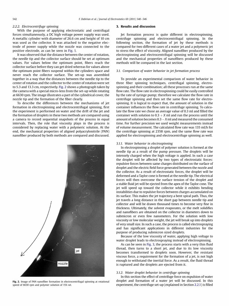
It was observed that the distance between the center of rotation,the needle tip and the collector surface should be set at optimumvalues. For values below the optimum point, fibers reach thecollector surface before they can get dried whereas for values abovethe optimum point fibers suspend within the cylinders space andnever reach the collector surface. The set-up was assembledtogether in a way that the distances between the needle tip to thecenter of rotation and the collector to the center of rotationwere setto 5.3 and 13.3 cm, respectively. Fig. 2 shows a photograph taken bythe camerawith a special micro-lens from the set-up while rotatingat 6630 rpm. The image illustrates a part of the cylindrical cover, thenozzle tip and the formation of the fiber clearly.
To describe the differences between the mechanisms of jetformation in electrospinning and electrocentrifugal spinning, firstthe experiment is performed on water and the drift of the jet andthe formation of droplets in these twomethods are compared usinga camera to record sequential snapshots of the process in equalintervals. Then, the role that viscosity plays in the process isconsidered by replacing water with a polymeric solution. At theend, the mechanical properties of aligned polyacrylonitrile (PAN)nanofiber produced by both methods are compared and discussed.
Fig. 2. Image of PAN nanofiber formation in electrocentrifugal spinning at rotationalspeed of 6630 rpm and polymer solution of 15% wt.
3. Results and discussion
Jet formation process is quite different in electrospinning,centrifuge spinning and electrocentrifugal spinning. In thefollowing section, the formation of jet by these methods iscompared for two different cases of a water jet and a polymeric jetto stress the effect of viscosity. Aligned nanofiber produced by theelectrospinning and electrocentrifugal spinning will be discussedand the mechanical properties of nanofibers produced by thesemethods will be compared in the last section.
3.1. Comparison of water behavior in jet formation process
To provide an experimental comparison of water behavior inthree fiber spinning techniques, centrifugal spinning, electro-spinning and their combination; all these processes run at the sameflow rate. The flow rate in electrospinning could be easily controlledby the rate of syringe pump; therefore we calculate the flow rate incentrifuge spinning and then set the same flow rate for electro-spinning. It is logical to expect that, the amount of solution in thecontainer influences the flow rate in centrifuge spinning. To calcu-late the flow rate we chose an average value of 0.3 ml and filled thecontainer with solution to 0.3 þ X ml and run the process until theamountof solution becomes 0.3�Xml andmeasured the consumedtime. For further precision we used weight measurements insteadof volume measurement. The calculated flow rate was 135 ml/h forthe centrifuge spinning at 2358 rpm, and the same flow rate wasapplied for electrospinning and electrocentrifuge spinning as well.
3.1.1. Water behavior in electrospinningIn electrospinning a droplet of polymer solution is formed at the
needle tip as a result of the pump pressure. The droplets will beintensely charged when the high voltage is applied. In such a casethe droplet will be affected by two types of electrostatic forces:repulsive forces between same charges distributed on the surface ofdroplet and the electric field force generated between the nozzle andthe collector. As a result of electrostatic forces, the droplet will bedeformed and a Taylor cone is formed at the needle tip. The electricalforces will then overcome the surface tension of the droplet anda stable fluid jet will be ejected from the apex of the Taylor cone. Thejet will speed up toward the collector while it exhibits bendinginstabilities due to repulsive forces between charges accumulated onits surface. This makes the jet trajectory a bent spiral path. Thus, thejet travels a long distance in the short gap between needle tip andcollector and will be drawn thousand times to become very fine inthickness. Ultimately, the solvent evaporates, or the melt solidifiesand nanofibers are obtained on the collector in diameters down tosubmicron or even few nanometers. For the solution with lowviscosity or lowmolecular weight, the jet will break up into dropletsof very small size. In such a case, the process is called electrosprayingand has significant applications in different industries for thepurpose of producing submicron sized droplets.
Because of the low viscosity of water, applying high voltage towater droplet leads to electrospraying instead of electrospinning.
As can be seen in Fig. 3, the process starts with a very thin fluidthread, then turns to a short jet, and due to its low viscositybecomes transformed to droplets soon. However, the resistantviscous force, a requirement for the formation of a jet, is not highenough to withstand the inertial force. As a result, the fluid threadis ruptured and the droplets are ejected from it.
3.1.2. Water droplet behavior in centrifuge spinningIn this section the effect of centrifuge force on expulsion of water
droplet and formation of a water jet will be discussed. In thisexperiment, the centrifuge set-up (explained in Section 2.2.1) isfilled

Fig. 5. Image of electrocentrifugal spinningofwater (2385 rpm,15 kV, 8 cmspinning gap).
Fig. 4. Images of water droplet formation, water jet ejection, and breaking up todroplets in centrifuge spinning at rotational speed of 2385 rpm.
Fig. 6. (a) Schematic illustration of jet path in electrospinning, and (b) Taylor con
Fig. 3. Images of water behaviors in electrospinning; a short unstable jet formed andturned into droplets soon.
F. Dabirian et al. / Journal of Electrostatics 69 (2011) 540e546 543
with water and rotated with various rotational speeds. The centri-fuge force pumps the fluid into the needle and, therefore, the flowrate is dependent on the rotational speed. Based on rotational speed,two different modes can be developed in the experiment. At lowerrotational speed water droplets will be formed and expelled outfrom the nozzle whereas a jet of fluid is generated at higherrotational speeds as can be seen in Fig. 4. The breakup of the jet intosmaller drops is also clearly observed in these images.
3.1.3. Water droplet behavior in electrocentrifugal spinningIn electrocentrifugal spinning the formation of the jet is solely
due to the centrifuge force which also drives the fluid into theneedle and a jet is formed without the development of the Taylorcone. The exit jet is then deformed by the electrostatic forces and ishighly stretched as shown in Fig. 6. This image was taken for theoperating conditions of 2385 rpm, 15 kV and 8 cm spinning gapbetween nozzle and collector. Again, due to the low viscosity ofwater, the stretching process cannot continue and as Fig. 5 clearlyshows, the growth of instability waves ultimately leads to thebreakup of the jet into small drops.
Comparing Figs. 3e5 reveals that by conjugate use ofelectrostatic and centrifuge forces, it is possible to achieve a stablejet at higher flow rates even for a low viscosity fluid as water. This isa significant factor in fabricating nanofibers by this method becauseit can increase the production rate considerably.
3.2. Comparison of polymer solution behavior
As explained in the previous section, the mechanism of jetformation and nanofiber production is different in electrospinningand electrocentrifugal spinning. In this section, the effect of theviscoelastic forces on the formation of the jet by these twomethodsis compared using a PAN solution instead of water.
3.2.1. Polymeric jet in electrospinningThe PAN solution can form a droplet stabilized by its surface
tension at the end of the needle tip. Strong electrostatic field isapplied to the droplet. The droplet will deform into a Taylor cone.When the applied voltage exceeds a critical value at which theelectrostatic force overcomes the surface tension and viscoelasticforces, a stable jet of polymer solution can be ejected from thedroplet. In contrast to previous experiment, due to the resistanceviscoelastic forces the jet is not broken up to the droplets. Instead,the ejected polymeric jet travels a short distance followinga straight path and then bending instability is developed in the jetdue to the mutually repulsive forces resulting from the electriccharges of the jet. Fig. 6 shows these three stages schematically andgraphically for electrospinning of 15% wt PAN solution.
e, straight section and spiral path in electrospinning of 15% wt PAN solution.

Fig. 7. Electrocentrifugal spinning of 15% wt PAN in DMF at rotational speed of6630 rpm.
F. Dabirian et al. / Journal of Electrostatics 69 (2011) 540e546544
3.2.2. Polymeric jet in electrocentrifugal spinningIn this method the polymeric jet is formed only by the
centrifugal force and undergoes elongation by the simultaneousaction of centrifugal and electrostatic forces until it lies down oncollector. Fig. 7 shows an image of the process using 15% wt PANsolution at the rotational speed of 6360 rpm. The ejected jet fromthe nozzle encounters bending instabilities after a short distancetraveling in a curved path. As it can be seen in this image, due tothe high flow rate, the Taylor cone has not appeared and thepolymeric fluid conforms to a jet as a consequence of the appliedcentrifugal force.
Fig. 8. Electrocentrifugal spinning of 16% wt PAN in DMF at rotational speed
Fig. 9. Scanning electron microscopy of nanofibers produced by electrocentrifugal spinninvoltage of 15 kV.
In comparison with electrospinning, bending instabilities areobserved with less frequencies and amplitude in electrocentrifugalspinning. This can be explained in this way: by increasing therotational speed, the relative velocity between the jet and thesurrounding air, which tends to dry up the solution, is increased.As a result, the growth of instability wave is suppressed due to theevaporation of solvent. On the other hand, by increasing thepolymer concentration, the polymeric bending instability of the jetis reduced and the jet travels in a straight path toward thecollector. This provides the possibility of collecting highly alignednanofibers on the outer cylinder. Fig. 8 shows images of electro-centrifugal spinning for 16% wt PAN at speed of 6360 rpm wherethe bending instabilities have considerably vanished and asa result, the polymeric jet takes on a completely straight andaligned form.
This method can be employed to produce highly alignednanofibers from solutions with high concentration. Fig. 9 showsa scanning electron microscopy of nanofibers produced by electro-centrifugal spinning of 15% and 16% wt PAN in DMF at rotationalspeed of 6360 rpm and applied voltage of 15 kV.
The morphology of nanofibers was studied and explained inprevious work [46]. In brief, as shown in Fig.10 the results indicatedthat the production of nanofibers with drop sprinklingwas possible,and at low rotational speed and concentrations, the nanofiberscontain drops and beads in centrifuge spinning. When using elec-trocentrifuge spinning, the nanofiber diameters have been changedcompared to centrifuge spinning. Results showed drastic reductionin fiber diameter which is the effect of adding electrical force tocentrifuge forces.
3.2.3. Comparison of mechanical propertiesThe mechanical properties of aligned nanofiber bundles were
measured by Zwick 1446e60. Zwick was set for constant rate ofelongation. To obtain load elongation curves, the sample lengthwas
of 6360 rpm where the bending instabilities are considerably reduced.
g of (a) 15% and (b) 16% wt PAN in DMF at rotational speed of 6360 rpm and applied
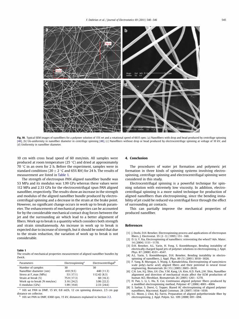
Fig. 10. Typical SEM images of nanofibers for a polymer solution of 15% wt and a rotational speed of 6615 rpm; (a) Nanofibers with drop and bead produced by centrifuge spinning[48], (b) Un-uniformity in nanofiber diameter in centrifuge spinning [48], (c) Nanofibers without drop or bead produced by electrocentrifuge spinning at voltage of 10 kV, and(d) Uniformity in nanofiber diameter.
F. Dabirian et al. / Journal of Electrostatics 69 (2011) 540e546 545
10 cm with cross head speed of 60 mm/min. All samples wereproduced at room temperature (25 �C) and dried at approximately70 �C in an oven for 2 h. Before the experiment, samples were instandard conditions (20 � 2 �C and 65% RH) for 24 h. The results ofmeasurement are listed in Table 1.
The strength of electrospun PAN aligned nanofiber bundle was53 MPa and its modulus was 1.99 GPa whereas these values were112 MPa and 2.33 GPa for the electrocentrifugal spun PAN alignednanofiber, respectively. The results showan increase in the strengthand modulus of the aligned nanofiber bundle produced by electro-centrifugal spinning and a decrease in the strain at the brake point.However, no significant change occurs in work up to break param-eter. The enhancements of mechanical properties can be accountedfor by the considerable mechanical contact drag forces between thejet and the surrounding air which lead to a better alignment offibers.Work up to break is a quantity which considers both strengthand strain simultaneously. An increase in work up to break isexpected due to increase of strength, but it should be noted that dueto the strain reduction, the variation of work up to break is notconsiderable.
Table 1The results of mechanical properties measurement of aligned nanofiber bundles byZwick.
Parameters Electrospinninga Electrocentrifugalb
Number of samples 30 30Nanofiber diameter (nm) 410 (9.5) 440 (11.3)Stress at F_max (MPa) 53 (17.1) 112.42 (8.3)Strain at break (%) 75.9 (17.3) 60 (16.3)Work up to break (N mm/tex) 3.16 (24.2) 3.06 (22.2)E-modulus (GPa) 1.99 (19.8) 2.33 (24.6)
a 16% wt PAN in DMF, 15 kV, 0.8 ml/h, 12 cm spinning distance, 2.5 cm gapdistance on collector.
b 16% wt PAN in DMF, 6360 rpm, 15 kV, distances explained in Section 2.2.
4. Conclusion
The procedures of water jet formation and polymeric jetformation in three kinds of spinning systems involving electro-spinning, centrifuge spinning and electrocentrifugal spinning wereconsidered in this study.
Electrocentrifugal spinning is a powerful technique for spin-ning solution with extremely low viscosity. In addition, electro-centrifugal spinning is a more suited technique for production ofaligned nanofibers than electrospinning, since the bending insta-bility of jet could be reduced via centrifugal force through the effectof surrounding air contacts.
This can partially improve the mechanical properties ofproduced nanofiber.
References
[1] J. Doshi, D.H. Reneker, Electrospinning process and applications of electrospunfibers, J. Electrostat. 35 (2e3) (1995) 151e160.
[2] D. Li, Y. Xia, Electrospinning of nanofibers: reinventing the wheel? Adv. Mater.14 (2004) 1151e1170.
[3] D.H. Reneker, A.L. Yarin, H. Fong, S. Koombhongse, Bending instability ofelectrically charged liquid jets of polymer solutions in electrospinning, J. Appl.Phys. 87 (2000) 4531e4547.
[4] A.L. Yarin, S. Koombhongse, D.H. Reneker, Bending instability in electro-spinning of nanofibers, J. Appl. Phys. 89 (5) (2001) 3018e3026.
[5] F. Yang, R. Murugan, S. Wang, S. Ramakrishna, Electrospinning of nano/microscale poly(L-lactic acid) aligned fibers and their potential in neural tissueengineering, Biomaterials 26 (15) (2005) 2603e2610.
[6] C.H. Lee, H.J. Shin, I.H. Cho, Y.M. Kang, I.A. Kim, K.D. Park, J.W. Shin, Nanofiberalignment and direction of mechanical strain affect the ECM production ofhuman ACL fibroblast, Biomaterials 26 (2005) 1261e1270.
[7] H. Pan, L. Li, L. Hu, X. Cui, Continuous aligned polymer fibers produced bya modified electrospinning method, Polymer 47 (2006) 4901e4904.
[8] S. Sarkar, S. Deevi, G. Tepper, Biased AC electrospinning of aligned polymernanofibers, Macromol. Rapid Commun. 28 (2007) 1034e1039.
[9] S.C. Moon, J. Choi, R.J. Farris, Preparation of aligned polyetherimide fiber byelectrospinning, J. Appl. Polym. Sci. 109 (2008) 691e694.
F. Dabirian et al. / Journal of Electrostatics 69 (2011) 540e546546
[10] X. Wang, K. Zhang, M. Zhu, H. Yu, Z. Zhou, Y. Chen, B.S. Hsiao, Continuouspolymer nanofiber yarns prepared by self-bundling electrospinning method,Polymer 49 (2008) 2755e2761.
[11] A. Baji, Y.W. Mai, S.C. Wong, M. Abtahi, P. Chen, Review: electrospinning ofpolymer nanofibers: effects on oriented morphology, structures and tensileproperties, Composites Sci. Technol. 70 (2010) 703e718.
[12] D. Li, Y. Wang, Y. Xia, Electrospinning of polymeric and ceramic nanofibers asuniaxially aligned arrays, Nano Lett. 3 (8) (2003) 1167e1171.
[13] D. Li, Y. Wang, Y. Xia, Electrospinning nanofibers as uniaxially aligned arraysand layer-by-layer stacked films, Adv. Mater. 16 (4) (2004) 361e366.
[14] R. Jalili, M. Morshed, S.A. Hosseini Ravandi, Fundamental parameters affectingelectrospinning of PAN nanofibers as uniaxially aligned fibers, J. Appl. Polym.Sci. 101 (2006) 4350e4357.
[15] G.H. Kim, Electrospinning process using field-controllable electrodes, J. Polym.Sci. Part B Polym. Phys. 44 (2006) 1426e1433.
[16] N. Chanunpanich, H. Byun, Alignment of electrospun polystyrene with anelectric field, J. Appl. Polym. Sci. 106 (2007) 3648e3652.
[17] B.S. Jha, R.J. Colello, J.R. Bowman, S.A. Sell, K.D. Lee, J.W. Bigbee, G.L. Bowlin,W.N. Chow, B.E. Mathern, D.G. Simpson, Two pole air gap electrospinning:fabrication of highly aligned, three-dimensional scaffolds for nerve recon-struction, Acta Biomater. 7 (2011) 203e215.
[18] A. Theron, E. Zussman, A.L. Yarin, Electrostatic field-assisted alignment ofelectrospun nanofibers, Nanotechnology 12 (2001) 384e390.
[19] H. Fong, W.D. Liu, C.S. Wang, R.A. Vaia, Generation of electrospun fibers ofnylon 6 and nylon 6-montmorillonite nanocomposite, Polymer 43 (3) (2002)775e780.
[20] M.B. Bazbouz, G.K. Stylios, Alignment and optimization of nylon 6 nanofibersby electrospinning, J. Appl. Polym. Sci. 107 (2008) 3023e3032.
[21] R. Dersch, T. Liu, A.K. Schaper, A. Greiner, J.H. Wendorff, Electrospun nano-fibers: internal structure and intrinsic orientation, J. Polym. Sci. Part A 41(2003) 545e553.
[22] E.P.S. Tan, S.Y. Ng, C.T. Lim, Tensile testing of a single ultrafine polymeric fiber,Biomaterials 26 (13) (2005) 1453e1456.
[23] D. Yang, B. Lu, Y. Zhao, X. Jiang, Fabrication of aligned fibrous arrays bymagnetic electrospinning, Adv. Mater. 19 (2007) 3702e3706.
[24] D. Yang, J. Zhang, J. Zhang, J. Nie, Aligned electrospun nanofibers induced bymagnetic field, J. Appl. Polym. Sci. 110 (2008) 3368e3372.
[25] J.A. Matthews, G.E. Wnek, D.G. Simpson, G.L. Bowlin, Electrospinning ofcollagen nanofibers, Biomacromolecules 3 (2) (2002) 232e238.
[26] M. Khamforoush, M. Mahjob, Modification of the rotating jet method togenerate highly aligned electrospun nanofibers, Mater. Lett. 65 (2011)453e455.
[27] J.M. Deitzel, J. Kleinmeyer, J.K. Hirvonen, T.N.C. Beck, Controlled deposition ofelectrospun poly(ethylene oxide) fibers, Polymer 42 (2001) 8163e8170.
[28] F. Dabirian, Design and Assembling of Yarn Production Unit of Nanofiber viaElectrospinning and Investigation of its Tensile Properties, Thesis (MSc),Isfahan University of Technology, 2006.
[29] F. Dabirian, S.A. Hosseini Ravandi, Iran patent, 2006, No. 34894.[30] F. Dabirian, S.A. Hosseini Ravandi, Production of bulk nanofibers layers by
manipulation of electrospinning system and investigation on some of theircharacteristics, Iran J. Polym. Sci. Technol. 4 (2008) 307e313.
[31] L. Rayleigh, On the instability of jets, Proc. Lond. Math. Soc. 10 (1878) 4e13.[32] C. Weber, Zum Zerfall eines Flussigkeitsstrahles, Z. Angew. Math. Mech. 11
(1931) 136e154.[33] D.B. Bogy, Drop formation in a circular liquid jet, Annu. Rev. Fluid Mech. 11
(1979) 207e228.[34] J. Eggers, Nonlinear dynamics and breakup of free-surface flows, Rev. Mod.
Phys. 69 (1997) 865e929.[35] S. Middleman, Modeling Axisymmetric Flows: Dynamics of Films, Jets, and
Drops, Academic Press, 1995.[36] J.H. Hilbing, S.D. Heister, Droplet size control in liquid jet breakup, Phys. Fluids
8 (1996) 1574e1581.[37] L. Partidge, D.C.Y. Wong, M.J.H. Simmons, E.I. Parau, S.P. Decent, Experimental
and theoretical description of the break-up of curved liquid jets in the prillingprocess, Chem. Eng. Res. Des. 83 (2005) 1267e1275.
[38] E.I. Parau, S.P. Decent, M.J.H. Simmons, D.C.Y. Wong, A.C. King, Non-linearviscous jets emerging from a rotating orifice, J. Eng. Math. 57 (2007) 159e179.
[39] J.B. Keller, S.I. Rubinow, Y.O. Tu, Spatial instability of a jet, Phys. Fluids 16(1973) 2052e2055.
[40] E.O. Tuck, The shape of free jets of water under gravity, J. Fluid Mech. 76(1976) 625e640.
[41] J.M. Vanden-Broeck, J.B. Keller, Jet rising and falling under gravity, J. FluidMech. 124 (1982) 335e345.
[42] V.M. Entov, A.L. Yarin, The dynamics of thin liquid jets in air, J. Fluid Mech. 140(1984) 91e111.
[43] F. Dias, J.M. Vanden-Broeck, Flows emerging from a nozzle and falling undergravity, J. Fluid Mech. 213 (1990) 465e477.
[44] A.L. Yarin, Free Liquid Jets and Films: Hydrodynamics and Rheology, Longman,New York, 1993.
[45] L.J. Cummings, P.D. Howell, On the evolution of non-axisymmetric viscous fibreswith surface tension, inertia and gravity, J. Fluid Mech. 389 (2001) 361e389.
[46] F. Dabirian, S.A. Hosseini Ravandi, A.R. Pishevar, Investigation of parametersaffecting PAN nanofiber production using electrical and centrifugal forces asa novel method, Curr. Nanosci. 6 (2010) 545e552.
[47] R.T. Weitz, L. Harnau, S. Rauschenbach, M. Burghard, K. Kern, Polymer nano-fibers via nozzle-free centrifugal spinning, Nano Lett. 8 (4) (2008) 1187e1191.
[48] F. Dabirian, S.A. Hosseini Ravandi, Process and apparatus electro-centrifugespinning for the production of nanofibers, Iran patent, 2005. No. 43162.