Embed Size (px)
Citation preview

i
A COMPARISON STUDY ON CONTROL MOMENT GYROSCOPE ARRAYS AND
STEERING LAWS
CHITIIRAN KRISHNA MOORTHY
A THESIS SUBMITTED TO THE FACULTY OF GRADUATE STUDIES IN PARTIAL
FULFILMENT OF THE REQUIREMENTS FOR THE DEGREE OF
MASTER OF SCIENCE
GRADUATE PROGRAM IN EARTH AND SPACE SCIENCE
YORK UNIVERSITY
TORONTO, ONTARIO
DECEMBER 2019
©CHITIIRAN KRISHNA MOORTHY, 2019

ii
Abstract
Current reaction wheels and magnetorquers for microsatellite are limited by low slew rate and
heavily depends on orbital parameters for coverage area. Control moment gyroscope (CMG)
clusters offer an alternative solution for high slew rates and rapid retargeting. Though CMGs
are often used in large space missions, their use in microsatellites is limited due to the stringent
mass budget. Most literature reports only on pyramid configuration, and there are no definite
cross comparison studies between various CMG clusters and steering laws.
In this research, a generic tool in Matlab and Simulink is developed to further understand CMG
configurations and steering laws for a microsat mission. Various steering laws necessary for
mitigating singularities in CMG clusters are compared in two distinct missions. The simulation
results were evaluated based on the pointing accuracy, platform jitter, and pointing stability
achieved by the spacecraft for each combination of CMG clusters, steering laws and
trajectories.
The simulation results demonstrate that the pyramid cluster is marginally better than the
rooftop cluster in pointing accuracy. The comparison of steering laws shows that,
counterintuitively, Singularity Robust steering law, which passes through singularities,
outperforms both Moore-Penrose and Local Gradient methods for almost all evaluation criteria
for the two missions it was tested on. The simulation results would aid systems engineers in
designing low-cost actuation systems and corresponding control software, which can increase
the data acquisition rate of remote sensing missions.

iii
Acknowledgments
Firstly, I would like to express my immense gratitude to Dr. Regina Lee for guidance from my
first step in masters and her patience throughout my master’s degree. Her kind approach and
farsightedness have prepared me for obstacles that I could not have anticipated both in
academic endeavours and graduate student duties.
I appreciate Dr. Alexander Frias for his help in his guidance in simulation. We have spent
valuable hours in-person or through emails, which helped me climb the technical learning
curve faster. I would also like to thanks Dr. Guy Benari for his guidance in solidifying the
master’s core concept.
I would like to thank my fellow colleagues in NanoSat Research Lab, who was always there
to lighten up the room and provide valuable thoughts while discussing specific of my thesis.
Some subsections would have been harder without them sharing their expertise with the lab.
I’m honoured Microsat Systems Canada Inc (MSCI) and Natural Science and Engineering
Reseach Council, NSERC, has funded this knowledge hunt.
Lastly, I would like to thank my parents and loved ones for their support in my journey far
from home.

iv
Table of Contents
Abstract ...................................................................................................................................... i
Acknowledgments.................................................................................................................... iii
Table of Contents ..................................................................................................................... iv
List of Tables .......................................................................................................................... vii
List of Figures .......................................................................................................................... ix
List of Acronyms ................................................................................................................... xiii
1 Introduction ....................................................................................................................... 1
1.1 Problem Statement ..................................................................................................... 1
1.2 Satellite actuators ....................................................................................................... 2
Reaction wheel .................................................................................................... 3
Torque rods ......................................................................................................... 4
Momentum wheel ............................................................................................... 6
Control Moment Gyroscope ............................................................................... 7
1.3 Research objective...................................................................................................... 9
1.4 Thesis Contributions ................................................................................................ 11
1.5 Thesis outline ........................................................................................................... 12
2 Principles of Control Moment Gyroscopes (CMG) ........................................................ 14
2.1 Background .............................................................................................................. 14

v
2.2 Advantages and disadvantages of CMG .................................................................. 17
2.3 Angular momentum envelope .................................................................................. 20
2.4 Singularities in CMG momentum space .................................................................. 23
2.5 Market survey of commercial-grade CMG .............................................................. 27
3 Simulation model of CMG configurations ..................................................................... 30
3.1 Reference frames ...................................................................................................... 30
3.2 DC motor model ....................................................................................................... 32
3.3 Single gimbal control moment gyroscope model, SGCMG .................................... 35
3.4 Control moment gyroscope cluster model ............................................................... 37
Rooftop cluster .................................................................................................. 38
Pyramid cluster ................................................................................................. 39
3.5 Control law ............................................................................................................... 41
3.6 Steering law .............................................................................................................. 43
Moore-Penrose Pseudoinverse .......................................................................... 45
Singularity robust inverse ................................................................................. 45
Local gradient ................................................................................................... 46
3.7 Mission profiles ........................................................................................................ 47
Ground communication maneuver .................................................................... 47
Sun vector avoidance trajectory ........................................................................ 52
4 Simulation results and analysis ....................................................................................... 58

vi
4.1 Evaluation criteria .................................................................................................... 58
4.2 CMG performance in Ground Communication Maneuver ...................................... 62
Pointing Accuracy ............................................................................................. 63
Jitter................................................................................................................... 66
Pointing Stability .............................................................................................. 69
4.3 CMG performance in sun vector avoidance maneuver ............................................ 75
Pointing Accuracy ............................................................................................. 76
Jitter................................................................................................................... 79
Pointing Stability .............................................................................................. 82
5 Final Remarks ................................................................................................................. 89
5.1 Future works ............................................................................................................. 93
6 References ....................................................................................................................... 96

vii
List of Tables
Table 1 CMG types based on the configuration of gimbal axis ............................................. 15
Table 2 Commercially-off-the-shelf CMGs for large satellites .............................................. 28
Table 3 Commercially-off-the-shelf CMGs compatible with small satellites. ....................... 29
Table 4 Keplerian Elements of NEOSSat ............................................................................... 53
Table 5 Typical pointing accuracy requirements of various satellite classes ......................... 59
Table 6 Typical jitter requirements of various satellite classes .............................................. 60
Table 7 Largest pointing error in ground communication maneuver for pyramid and rooftop
cluster for all steering laws ..................................................................................................... 63
Table 8 Largest jitter for ground communication maneuver for pyramid and rooftop cluster for
all steering laws....................................................................................................................... 66
Table 9 Pointing stability for two-second integration window during ground communication
maneuver for pyramid and rooftop cluster for all steering laws ............................................. 72
Table 10 Pointing stability for hundred-second integration window during ground
communication maneuver for pyramid and rooftop cluster for all steering laws ................... 72
Table 11 Largest pointing error in sun vector avoidance maneuver for pyramid and rooftop
cluster for all steering laws ..................................................................................................... 76
Table 12 Largest jitter in sun vector avoidance maneuver for pyramid and rooftop cluster for
all steering laws....................................................................................................................... 79
Table 13 Pointing stability for two-second integration window while sun vector avoidance
maneuver for pyramid and rooftop cluster for all steering laws ............................................. 85

viii
Table 14 Pointing stability for 100-second integration window while sun vector avoidance
maneuver for pyramid and rooftop cluster for all steering laws ............................................. 86

ix
List of Figures
Figure 1 Cross-sectional view of a reaction wheel [10] .......................................................... 4
Figure 2 Torque rods made by copper wire wound on iron core [11]. .................................... 6
Figure 3 Working principle of single gimbal control moment gyroscope (SGCMG) .............. 7
Figure 4 Traditional push-broom technique with nadir pointing imager .................................. 9
Figure 5 Imaging platform with adjustable footprint for greater throughput ......................... 10
Figure 6 Angular momentum envelope of a single SGCMG is a circle ................................. 21
Figure 7 Angular momentum envelope (AME) of pyramid cluster ....................................... 22
Figure 8 Angular momentum envelope (AME) of rooftop cluster ......................................... 23
Figure 9 Internal singularity due to momentum vectors aligning [10] .................................. 25
Figure 10 References frame of pyramid cluster and Attitude Control System coincides. ...... 32
Figure 11 Simulated DC motor verification with Faulhaber DC motor 2224 SR .................. 34
Figure 12 Single gimbal control moment gyroscope .............................................................. 35
Figure 13 Change in angular momentum vector and torque vector with respect to rotation about
the gimbal axis ........................................................................................................................ 36
Figure 14 Angular momentum and torque vector in terms of 𝛿𝑖 at different timestamps ...... 37
Figure 15 Rooftop cluster model ............................................................................................ 38
Figure 16 Pyramid cluster model ............................................................................................ 40
Figure 17 Angular relationship between spacecraft, ground target and earth’s center. .......... 48
Figure 18 Pitch command for a spacecraft tracking a communication tower from an altitude of
600km above the ground. Pitching direction changes at 388 seconds. ................................... 49

x
Figure 19 Pitch rate command for a spacecraft tracking a communication tower from an altitude
of 600km above the ground. Change in pitch rate when satellite crosses ground station at 388
seconds. ................................................................................................................................... 50
Figure 20 Pitch acceleration command of ground communicationmission. High slew rates at
the begining and end of the manuever is shown in smaller figure. ......................................... 51
Figure 21 Angular difference between sun vector and payload vector in NEOSSat inertial
frame. NEOSSat reorients the optical payload from 90o deg to -90o deg. .............................. 54
Figure 22 NEOSSat angular velocity during a sun avoidance maneuver derived from potential
field method. ........................................................................................................................... 55
Figure 23 NEOSSat Euler angles from the integration of angular velocity. .......................... 56
Figure 24 Pitch angle command for maintaining communication with ground tower during the
inflection point in spacecraft flyby. ........................................................................................ 62
Figure 25 Pointing error during flyby over the ground tower with pyramid cluster. Moore
Penrose, MP, Singularity Robust Inverse, SRI, and Local Gradient, LG, have overlapping
performance in individual axis................................................................................................ 64
Figure 26 Pointing error during flyby over the ground tower with rooftop cluster. Moore
Penrose, MP, Singularity Robust Inverse, SRI, and Local Gradient, LG, have overlapping
performance in individual axis................................................................................................ 65
Figure 27 Comparison of jitter in pyramid cluster while performing ground communication
maneuver with all three steering laws; Moore Penrose, MP, Singularity Robust Inverse, SRI,
and Local Gradient, LG. ......................................................................................................... 67

xi
Figure 28 Comparison of jitter in rooftop cluster while performing ground communication
maneuver with all three steering laws; Moore Penrose, MP, Singularity Robust Inverse, SRI,
and Local Gradient, LG. ......................................................................................................... 68
Figure 29 Spacecraft pointing-stability over a 2-second interval; Comparing all steering law
with pyramid cluster for ground communication maneuver. .................................................. 70
Figure 30 Spacecraft pointing-stability over a 2-second interval; Comparing all steering law
with rooftop cluster for ground communication maneuver .................................................... 71
Figure 31 Comparison of Moore-Penrose, MP, Singularity Robust Inverse, SRI, and Local
Gradient method, LG, with pyramid cluster for scenario ground communication maneuver in
terms of pointing stability ....................................................................................................... 73
Figure 32 Comparison of Moore-Penrose, MP, Singularity Robust Inverse, SRI, and Local
Gradient method, LG, with rooftop cluster for scenario ground communication maneuver in
terms of pointing stability ....................................................................................................... 74
Figure 33 NEOSSat quaternion commands for sun vector avoidance maneuver. .................. 75
Figure 34 NEOSSat pointing error for sun vector avoidance maneuver with the pyramid all
steering laws; Moore Penrose, MP, Singularity Robust Inverse, SRI, and Local Gradient, LG.
................................................................................................................................................. 77
Figure 35 NEOSSat pointing error for sun vector avoidance maneuver with the rooftop cluster
for all steering laws; Moore Penrose, MP, Singularity Robust Inverse, SRI, and Local Gradient,
LG. .......................................................................................................................................... 78
Figure 36 Comparison of jitter in NEOSSat while actively pointing optical payload away from
sun vector with the pyramid for all three steering laws; Moore Penrose, MP, Singularity Robust
Inverse, SRI, and Local Gradient, LG. ................................................................................... 80

xii
Figure 37 Comparison of jitter in NEOSSat while actively pointing optical payload away from
sun vector with the rooftop for all three steering laws; Moore Penrose, MP, Singularity Robust
Inverse, SRI, and Local Gradient, LG. ................................................................................... 81
Figure 38 Pointing stability of NEOSSat with the pyramid cluster for the 2-second interval
during sun vector avoidance maneuver ................................................................................... 83
Figure 39 Pointing stability of NEOSSat with the rooftop cluster for the 2-second interval
during sun vector avoidance maneuver. .................................................................................. 84
Figure 40 Pointing stability of NEOSSat with the pyramid cluster for the 100-second interval
during sun vector avoidance maneuver. .................................................................................. 87
Figure 41 Pointing stability of NEOSSat with the rooftop cluster for the 100-second interval
during sun vector avoidance maneuver. .................................................................................. 88
Figure 42 Initial hardware prototype with servomotors as gimbal. ........................................ 94
Figure 43 SGCMG for the new prototype with stepper motor and Raspberry Pi Zero .......... 95

xiii
List of Acronyms
ACS Attitude Control System
AME Angular momentum envelope
CMG Control moment gyroscope
CRDI Command Devices Research Institute
DGCMG Double gimbal control moment gyroscope
ECI Earth-centred Inertial
EKF Extended Kalman Filter
IMU Inertial Measurement Unit
ISS International space station
MSS Multi-Spectra Scanner
NEOSSat Near-Earth Object Surveillance Satellite
OLI Operational Land Imager
SGCMG Single gimbal control moment gyroscope
SSP Subsatellite point
UTC Coordinated Universal Time
VSCMG Variable speed control moment gyroscope

1
1 Introduction
1.1 Problem Statement
Remote sensing has been a major driving force behind the rapid development of the space
industry [1]. Cartography, meteorology, hydrology and many more commercial fields benefit
from space-based global imaging. Satellite-based remote-sensing is also crucial for disaster
monitoring landslides, volcanic eruptions and for assessing disaster zone for response
coordination. Apart from the core funding from military usage, financial aid from governments
is also used for forestry, agriculture and for monitoring urban land use [1].
In the early space era, rolled films capture ground images from an altitude of 150km [2]. The
Corona project collected eight hundred thousand images using KH-4B cameras, where the
films were dropped from space for post-processing [2]. The resolution of the target directly
under line of sight is 0.8 m per pixel, which is notably impressive for an analog system.
Nevertheless, the presences of clouds and other artifacts in, line of sight with the ground targets
yields no usable data. Moreover, successful imaging is still subjected to diffraction, image
motion and camera’s exposure time.
With the introduction of digital imaging techniques and the use of various electromagnetic
bands, the spatial resolution of images improved to 56m in cross-track and 80m along-track
direction for Landsat-1 [3]. Multi-Spectral Scanner in Landsat-1 provides green, red and two
more infrared band images at different resolutions [3]. Recently launched Landsat-8
Operational Land Imager (OLI) has further improved the resolution and provides imaging
services in eleven electromagnetic bands [4].

2
Imaging sensors such as CMOS cells have advanced from 2𝜇𝑚 to 0.25𝜇𝑚 in 1996 and
currently have further miniaturized to 0.1𝜇𝑚, which increases the resolution of captured
images [5]. Apart from resolution, the dynamic range of CMOS imagers have improved up to
140dB, surpassing dynamic range of 50-70dB of typical CCD imager [6]. Dynamic range is
the ratio of saturation signal to the root mean square noise floor and human eyeballs have an
impressive range of 200dB. The higher dynamic range reflects the quality of raw images from
remote sensing platforms. The speed of image acquisition is detrimental for remote sensing
since the spacecraft is moving at speeds above thousands of kilometers per hour and
susceptible to images smearing. CCD imagers have reached 0.25 MPx with an acquisition
speed of 1000 frames per second [7]. Similarly, CMOS imagers with electronic shutters have
a shutter speed of 2 milliseconds with a dynamic range comparable to CCD imagers at 57dB
[8].
In order to support an advanced imaging system on a space-borne platform, the pointing
stability and slew rate of the host satellite plays a crucial role in remote sensing missions. The
question now is, can the remote sensing industry take advantage of advancement in optical
technology and package it in microsatellite form with sufficient attitude control authority to
maximize the remote sensing throughput. In the next subsection, actuators used in
microsatellites are discussed with the latter question in mind.
1.2 Satellite actuators
The positioning requirements for actuators vary from mission to mission. Some satellites with
optical payloads require high pointing precision for a brief time window to achieve mission

3
objectives, for example, the Hubble Telescope. Meanwhile, a microgravity study on a plant
specimen in 3U AOSAT-1 requires a slow rotational rate, 1 rpm, for hours [9].
There are several types of actuators for satellite attitude control to address different needs of
mission requirements. The list for control actuators includes reaction wheel, momentum wheel,
control moment gyroscope, thrusters, magnetorquers and solar sail. Each type of actuator
comes with its advantages and disadvantages. Thus, there is a tradeoff between resources and
performance.
Reaction wheel
The flywheel in the reaction wheel produces torque by accelerating it. The spin direction
depends on the disturbance torque, 𝜏𝑑, or the desired attitude. The angular acceleration of
flywheel, �̇�𝑟𝑤, is related to the satellite’s body acceleration, �̇�𝑠, by the conservation of angular
momentum in equation (1.1).
𝐼𝑟𝑤�̇�𝑟𝑤 + 𝐼𝑠�̇�𝑠 = 𝜏𝑑 (1.1)
The reaction wheels are designed to rotate minimally during most of the mission operation and
capable of addressing predicted disturbance torque. In the equation above the terms 𝐼𝑟𝑤 and 𝐼𝑠
represents inertia of reaction wheel and spacecraft respectively.When the satellite mission
requires active tracking of an object, the reaction wheels continue to alter acceleration, �̇�𝑟𝑤,
until the tracking maneuver is satisfied. Any disturbance torque, 𝜏𝑑, on the spacecraft frame is
transferred to the reaction wheel by letting the wheel absorb the torque from the spacecraft
body’s angular momentum.

4
Figure 1 Cross-sectional view of a reaction wheel [10]
This incremental addition of angular acceleration slowly saturates the reaction wheel. The
reaction wheel, when it saturates, can no longer make torque corrections to control the
satellite’s attitude because the wheel’s current speed exceeds the predetermined maximum
[11]. When the angular acceleration of the flywheel exceeds the physical limitation, the system
fails and is no longer capable of satisfying mission requirements. In order to prevent reaction
wheel saturation, additional actuators such as torque rods are used to desaturate the reaction
wheel. Reaction wheel are ideal for small slew rates because the torqueing axis is fixed which
gives great control over the magnitude of resultant torque.
Torque rods
Torque rods or magnetorquers are electromagnets designed to produce an asymmetric
magnetic field. By controlling the flow of current through the coils of electromagnets, a
magnetic dipole with the desired magnetic field is produced. The torque rod’s magnetic field,
then, interacts with the earth’s ambient magnetic field as described in (1.2).

5
‖𝐵𝑒‖ ≅
7.96 ∗ 1015
𝑟𝑎𝑙𝑡3 𝑊𝑏𝑚
(1.2)
This interaction produces a resultant torque required for attitude control. A typical torque rod
produces a moment of ‖𝑀‖ ≅ 10𝐴𝑚2 − 100𝐴𝑚2 [12]. The product of the earth’s magnetic
field and torque rod’s magnetic dipole moment is the control torque generated by
magnetorquers. In addition to that, the control torque produced for attitude correction also
depends on the angle between torque rod and magnetic field line, denoted as ′𝛼′ in equation
(1.3). The maximum torque is produced when earth’s magnetic field and torque rod’s dipole
moment are perpendicular to each other.
𝑇 = ‖𝑀‖‖𝐵‖ sin(𝛼) (1.3)
The torque produced can be used to control the satellite’s attitude within 0.87 − 8.7 mrad
pointing precision or used in conjunction with reaction wheels to achieve finer control and
provide desaturation [13]. Most spacecraft rely on magnetorquers for de-tumbling, attitude
corrections with low pointing precision. When the dipole moment and the earth’s magnetic
field is parallel, 𝛼 = 0, no torque is produced, 𝑇 = ‖𝑀‖‖𝐵‖ sin(𝛼) = 0. Therefore,
spacecraft with a single torque rod is unable to produce a rotational movement about the earth’s
magnetic field line. In terms of attitude control, a spacecraft equipped with one torque rod can
only achieve 2-axis control when one of the torque rods aligns with earth’s magnetic field line.
Nevertheless, predictive control laws and accurate models of earth’s magnetic field lines can
mitigate the control issue [12]. Torque rods by itself provides very slow or passive attitude
control. When used in conjunction with reaction wheel, torque rods help in momentum
dumping which can extend the lifetime of Attitude Control System (ACS).

6
Figure 2 Torque rods made by copper wire wound on iron core [11].
Momentum wheel
Momentum wheels are akin to reaction wheels, but the flywheel spins at a constant speed.
Momentum wheel nominally spins at high speed and has a large angular momentum. The
momentum wheel absorbs disturbance torques, which decreases the momentum wheel speed.
By minimal change in input voltage of momentum wheel’s motor via feedback law, the spin
rate of momentum wheel and angular momentum is restored. This method of resisting torque
disturbance is known as active spin stabilization. The satellite’s orientation is controlled by
changing the individual rotation rate of flywheels based on the following equations of three
momentum wheel system [14].
𝐼𝑥𝑚𝑤�̇�𝑥
𝑚𝑤 + (𝐼𝑧𝑚𝑤 − 𝐼𝑦
𝑚𝑤)�̇�𝑧𝑚𝑤�̇�𝑦
𝑚𝑤 = 𝐼𝑥𝑠𝑐�̇�𝑥
𝑠𝑐
𝐼𝑦𝑚𝑤�̇�𝑦
𝑚𝑤 + (𝐼𝑥𝑚𝑤 − 𝐼𝑧
𝑚𝑤)�̇�𝑥𝑚𝑤�̇�𝑧
𝑚𝑤 = 𝐼𝑦𝑠𝑐�̇�𝑦
𝑠𝑐 (1.4)
𝐼𝑧𝑚𝑤�̇�𝑧
𝑚𝑤 + (𝐼𝑦𝑚𝑤 − 𝐼𝑥
𝑚𝑤)�̇�𝑦𝑚𝑤�̇�𝑥
𝑚𝑤 = 𝐼𝑧𝑠𝑐�̇�𝑧
𝑠𝑐
Equation (1.4) shows the relationship between the momentum wheel’s torque and the
spacecraft’s net torque. The inertia of momentum wheel, 𝐼𝑖𝑚𝑤, and inertia of spacecraft, 𝐼𝑖
𝑠𝑐,

7
dictates the angular acceleration of momentum wheel, �̇�𝑖𝑚𝑤, to achieve desired angular
acceleration of spacecraft, �̇�𝑖𝑠, where ′𝑖′ represents the axes in ACS frame.
Control Moment Gyroscope
A control moment gyroscope (CMG) consists of two main components: a flywheel and a
gimbal. The flywheel spins on a single axis often at thousands of rotations per minute (rpm),
resulting in very high angular velocity. Although high, the resulting angular momentum is
constant with the flywheel spin rate, Ωf; often decided depending on the spin axis inertia of the
flywheel. A gimbal rotates the flywheel about an axis perpendicular to the flywheel spin axis.
Controlling the gimbal rate produces precise torque production perpendicular to both gimbal
and flywheel spin axis [15], [16]. The torque amplification factor rises from equation of
motion where the two velocity components produce Coriolis force.
Figure 3 Working principle of single gimbal control moment gyroscope (SGCMG)

8
Figure 3 illustrates a simple representation of single gimbal control moment gyroscope
(SGCMG), where the spinning flywheel produces angular momentum, ℎ. When a gimbal rate,
�̇�, is introduced in 𝑔 axis, a resultant torque, 𝜏 = �̇� × ℎ is produced.
As the flywheel axis rotates 𝛿 angle about 𝑔 axis, the direction and magnitude of the CMG’s
net angular momentum changes with time. A gimbal rate with lower velocity, usually a few
degrees per second, produces low torque output that “directs” the flywheel’s angular
momentum within the angular momentum envelope, defined in section 2.3. The change with
respect to time in angular momentum is the generated torque. The general equation of torque
produced by CMG is, therefore, 𝜏𝑐𝑚𝑔 = �̇� × ℎ = −𝜏𝑠𝑐, where, �̇� , is the gimbal rate [17]. The
spacecraft torque vector is negative since it opposes the torque generated by CMG. The low
gimbal rate in single gimbal control moment gyroscope, SGCMG, acts as a torque amplifier
by producing a greater net CMG torque output via small gimbal torque input..
Different variations of CMG, such as dual gimbal control moment gyroscope (DGCMG) and
variable speed control moment gyroscope (VSCMG) exist, and each type can be clustered into
various configurations. One can characterize CMG based on the maximum torque generated,
momentum capacity, maximum gimbal rate and acceleration [18]. Similarly, the CMG cluster
can be categorized based on angular momentum envelope, internal and external singularities
[10], as will be described in section 3.4.
Two main types of CMGs are single gimbal and double gimbal CMGs. Though single gimbal
CMGs are better in terms of mechanical simplicity and higher output torque than double
gimbal CMGs, the control of single gimbal CMGs has an inherent singularity problem. At a
singularity condition, the system cannot produce any torque as explained in section 2.4 [16].

9
CMG rivals a reaction wheel with its high output torque and rapid response. It is employed in
large manned spacecrafts, such as the Internation Space Station (ISS). CMG is also a candidate
actuator for space robots since moments applied to spacecraft body is none to minimal [19],
[20].
1.3 Research objective
Current space missions collect data via push-broom technique where the optical payload is
pointed at ground regions for imaging. While orbiting the earth, the imaging platform, with the
aid of an oscillating mirror scans the ground perpendicular to the satellite trajectory. This
continuous scanning in perpendicular direction resembles a push broom sweeping area under
the satellite. The push-broom method is reliable, though susceptible to missed opportunities.
Figure 4 depicts the traditional data collection method. When the clouds cover the ground
target, the imager yields no usable data.
Figure 4 Traditional push-broom technique with nadir pointing imager

10
During this downtime, the optical payload can be repurposed for an adjacent target. Rapid
retargeting requires an actuator that can produce high torque outputs in short bursts. Actuators
from previous sections, apart from CMGs, have constraints in slew rate due to the inability to
change direction of momentum vector but rather rely on changing the magnitude of the
momentum vector. As a result, common spacecrafts are restricted to a slewing rate of 3o deg
per second. Considering the torque output of CMG, the ability to redirect the momentum vector
and the low power consumption, CMG cluster offers a good solution for the problem statement.
Recent advancements in optical technologies allow miniaturization of optical payloads for
space missions as discussed in the problem statement. The control authority of CMGs coupled
with advancements in the miniaturized optical payloads allows remote sensing solutions to be
packaged in a microsatellite class while further increasing the throughput via a rapid
retargeting method by reorienting the satellite to have a footprint as shown in Figure 5.
Figure 5 Imaging platform with adjustable footprint for greater throughput

11
Therefore, this thesis aims to develop a comprehensive tool to test the feasibility and compare
two CMG configurations working with two steering laws in simulated environment. The
simulation scenarios are designed to represent two fundamental roles, ground communication
and sun vector avoidance, as discussed in section 3.7. The scenarios aim to demonstrate one
axis control maneuver and multi-axis control maneuver which are preliminary for the rapid
retargeting manuevers. The CMG configurations and steering laws are evaluated based on the
satellite’s flight performance defined in 4.1 under the simulated trajectory. In this simulation
study, parameters for NEOSSat was used. However, the tools developed are compatible with
all classes of satellites.
1.4 Thesis Contributions
In this thesis, we provide a comprehensive study of CMGs usage for a microsatellite, such as
NEOSSat. This comparison study compares various mission scenarios, CMG clusters and
steering laws. The analysis from the simulation results will aid in the attitude control system
(ACS) related design decisions and provide critical information necessary for CMG sizing.
Furthermore, the interaction between stored momentum and steering law provides details for
mechanical sizing. Based on the desired maneuver of the mission at hand, one can use the
simulation model from the thesis to test and decide appropriate cluster type and steering law.
The simulation model for the SGCMG cluster is developed using the “first principle”
modelling methodology, where individual rigid bodies are modelled separately and integrated
with other rigid bodies such as flywheel and spacecraft framework. This method provides
modularity to the simulation such that copies of SGCMG can be rearranged in a different
configuration, saving development time in future simulation studies. Two types of CMG

12
cluster, namely pyramid and rooftop, is modelled and compared for their performance with
three different steering laws. The cluster type and steering laws are permutated for two
missions. The simulation results are compared for pointing accuracy, imaging platform jitter
and stability over two different time windows.
1.5 Thesis outline
In this chapter, the background of remote sensing satellites and optical payload technologies
were briefly discussed. Different types of satellite actuators were introduced with their
advantages and disadvantages. In Chapter 2, the single gimbal control moment gyroscope’s
working principles are presented in detail. This chapter provides the foundation for the
terminology used in this thesis. The advantages and disadvantages of CMG based actuators are
discussed. The following sections explain the angular momentum envelope and singularities
of CMG clusters in this study. A comprehensive market survey of CMGs in academic
institutions and space industry illustrates the current trend in the field of control moment
gyroscope in terms of actuator mass, torque capacity and power consumption.
Chapter 3 begins with an explanation of reference frames and the building blocks of the
simulation model. Various ways of assembling SGCMG into CMG clusters are illustrated. The
control law that generates the command torque based on the given mission profile is explained.
Steering law, which translates the command torque into the gimbal velocity command, is also
presented. Lastly, the trajectory for two maneuvers expected of any spacecraft is presented
along with design considerations.
The results from the simulation model are presented in Chapter 4. The evaluation criteria used
for this thesis are defined for clear interpretation. The simulation results are categorized by the

13
mission. In each mission, the results are provided in individual sections for each evaluation
criterion with analysis.
Final remarks summarizing the topics covered in this thesis and the outcomes of the simulation
results are presented in Chapter 5. A brief description of future work is provided, concluding
the thesis.

14
2 Principles of Control Moment
Gyroscopes (CMG)
Various space missions have benefited from control moment gyroscope (CMG) based
actuation working in tandem with custom steering laws designed for a specific mission. This
chapter presents a quick overview of CMGs’ legacy in the space industry. The working
principle of CMG provided in Chapter 1 is expanded further in the following subsection.
Angular momentum envelope and singularities of CMG clusters are explained. A
comprehensive market survey of commercially off the shelf SGCMG is provided at the end of
this chapter.
2.1 Background
The components of a CMG are explained in detail in the next chapter. Two important
component that dictates the category of a CMG are the number of gimbals and the speed of the
flywheel. A CMG with variable flywheel speed is referred to as variable speed CMG
(VSCMG), whereas a CMG with predetermined flywheel speed is simply a CMG.
Furthermore, a CMG can be either single gimbal CMG (SGCMG) or dual gimbal CMG
(DGCMG). This comparison study uses SGCMG with fixed speed flywheel.
The pattern in which the individual CMGs are clustered together determines the torque
capabilities of the clusters. The gimbal axes determine the category of a particular cluster. If a
cluster has a parallel gimbal axis, then the cluster is classified as Multiple Type [16]. Likewise,
if there are no parallel gimbal axes, then a cluster is categorized as Independent Type [16].

15
Table 1 CMG types based on the configuration of gimbal axis
Independent Type Configuration Multiple Type Configuration
Examples: pyramid, polygonal cluster Examples: Rooftop, scissor pairs
In the mid-1960s, the control moment gyroscope (CMG) began to stir interest as an attitude
actuator despite the design complexity. NASA funded research efforts started considering
CMG as an actuator for artificial satellites during this era. NASA’s ‘Skylab’ project intended
to use CMG for attitude control and gimballing Apollo Telescope Mount [21] [22]. The
research included mechanical studies of bearings and motors suitable for CMG usage. Studies
for CMG steering laws and a compliant attitude control system were in parallel since testing
CMG required them.
Primary constraints in the early days, and now, that dictate the research direction are weight
and power consumption. The onboard processing unit lacked the necessary power necessary
for real-time matrix inversions, unlike current microprocessors. The actuator research for
‘Skylab’ compared a twin type CMG system made of two single gimbals CMGs driven in

16
opposite directions and triplet double gimbal CMG (DGCMG) system. The twin type CMG
required a more straightforward control system since the resultant torque vector of twin type
CMG is unidirectional. In contrast, an approximated inverse matrix method was necessary to
overcome the inverse matrix computation of DGCMG. Three DGCMGs were installed on
Skylab, and a transposed Jacobian matrix was used to estimate the matrix inversion for steering
law [23]. The triple DGCMG cluster completed its mission, though one of the CMGs became
nonfunctional during the flight [24]. After that, studies of DGCMGs have continued for future
applications in the space station “Freedom,” which is now called International Space Station
(ISS).
CMG clusters have established a working legacy in large spacecrafts. Now, the attention is
shifting towards taking advantage of this technology in satellites lighter than 500kg medium-
sized spacecraft. The pyramid cluster is an independent type CMG configuration, as shown in
Table 1, became a standard actuation solution for medium-sized star gazing missions due to
large and well-distributed angular momentum envelope, explained in the next section. Pyramid
cluster’s momentum envelope is almost spherical, which translates into equal torqueing
capability in all the axis.
Furthermore, CMG clusters consisting of SGCMGs were also used in satellites such as the
‘High Energy Astronomical Observatory (HEAO)’ and the ‘Large Space Telescope (LST)’
[25]. A rooftop CMG cluster, explained in 3.4.1, was chosen for these missions since the
mathematical formulation for singularity is simpler than that of the pyramid type and,
therefore, easier implementation of the control algorithm.
S.C. Rybak from The Bendix Corporation claims 1.21 × 10⁻⁸rad for worse case pointing
error in the x-axis of Large Space Telescope, LST [26]. The CMG cluster in LST, initially

17
designed to be a redundancy in the control system, were capable of independent control torque
generation. The CMGs, however, experiences limit cycles in a torque-free condition where the
system vibrates between different states with same energy level. Nevertheless when small
torques are applied on the satellite the limit cycle stops [26]. Recently, the Starlink project by
SpaceX intends to provide global internet coverage with 30000 satellites orbiting at Low Earth
Orbit (LEO) and each of the satellite uses four control moment gyroscope for attitude control
[79].
2.2 Advantages and disadvantages of CMG
Control moment gyroscopes store kinetic energy in the flywheel as angular momentum. The
net change in the magnitude and direction of the angular momentum causes the resulting
torque. The physics of the system is further elaborated in section 3.3.
One major advantage of the control moment gyroscope is storing and releasing energy back
for satellite usage. Richie (2019) has shown that 80% of the kinetic energy can be harvested
back for electrical usage for life cycles beyond a hundred thousand [27] [28]. Combining the
attitude control system and power system further reduces mass consumption by the subsystem
[28].
Torque is the result of the change in the angular momentum of a system. Reaction wheels
produce torque by changing the acceleration of the flywheel while the angular momentum
direction is kept constant. Control moment gyroscopes, on the other hand, are free to change
the magnitude and the direction vector of angular momentum. In single gimbal control moment
gyroscopes, SGCMGs, the magnitude of flywheel angular momentum is held constant while
the vector changes via gimbaling. Since gimbaling requires significantly less power compared

18
to accelerating a flywheel, the peak power consumption of CMGs is relatively low. The
average power consumption of a CMG in an experiment by the University of Surrey is 25%
more efficient at 1.61 watts for a 40o deg yaw slew [29]. In terms of execution time, UoSat-12
with reaction wheels needed 200 seconds to complete the same maneuver, whereas the CMG
cluster took only 20 seconds [29] [30]. SSTL Micro reaction wheel used in Tsinghua-1
required 0.45 watt power for the same maneuver, which is significantly lower than the CMG
compared by Lappas from University of Surrey. However, the micro reaction wheels were
twice as heavy and are only capable of producing a maximum torque of 10mNm, whereas the
CMGs produced 52.25mNm [29], [31].
Control moment gyroscopes have disadvantages in other areas. Unlike the reaction wheel or
magnetorquers, CMGs have numerous moving parts and thus increases the risk factor due to
mechanical complexity [32]. One must also consider the interaction between the parts while
preparing the risk matrix for a mission with a CMG actuator. The bearing friction of the gimbal
is non-linear and causes additional complexity in the dynamic model [33], which requires
sophisticated control. Stiction, and kinetic friction are the three frictional components that
contribute to nonlinearity in SGCMG [26]. The frictional torque causes limit cycles, and the
amplitude of the oscillation depends on the control loop bandwidth. A faster control loop
results limit cycle of smaller amplitude at the cost of higher limit cycle frequency.
Motors used in CMG clusters also add to the nonlinearities due to flux distortions, motor
cogging and current ripples [34], [35]. Various disturbance attenuation strategies have been
proposed. Robust control algorithms were tested with ultrasonic motors as gimbal motors and
were able to achieve less than 0.5o deg/s speed error [36]. Sliding mode control and Extended
Kalman Filter (EKF) on permanent magnet synchronous machine shows a three-fold

19
improvement on settling time, from 75 ms to 28 ms [37]. CMGs with magnetic bearings reduce
the nonlinearities such as friction and stiction in the system. Internal model control
implemented for a bearingless permanent magnet synchronous motor has proven to have
reduced the settling time three-fold [38]. This further reduced the tracking errors in flywheel
without any influences on disturbance rejection [38]. Any imbalance in the flywheel
propagates into the system as high-frequency noise. Meanwhile, the gimbal motor produces
low-frequency disturbance due to a low gimbal rate. Considering the wide bandwidth of
disturbance torque on the CMGs, one major disadvantage is the control algorithm for CMGs
is complicated and computationally expensive.
A comparison between commercially available CMG and reaction wheel by Votel [1] shows
that CMGs are more efficient in producing torque from stored momentum than the reaction
wheel for any stored angular momentum class. As the flywheel mass increases, specific angular
momentum increases and the torque produced by CMG is orders of magnitude greater than the
reaction wheel. Following Votel’s research, CMGs are power-efficient when compared with
the reaction wheel with the same flywheel spin inertia. Nevertheless, reaction wheels are better
at producing large momentum but at a slower pace than CMGs. CMGs are capable of small-
angle maneuvers at a high slew rate [39].
There is also a limitation on the momentum to volume ratio of CMG systems. A CMG requires
moving parts and thus free space for the flywheel to be gimballed. Nonetheless, SwampSat
from the University of Florida have demonstrated a 500g CMG cluster packed within
100mm × 100mm × 50 mm or 0.5U form factor [40] [41].
In summary, CMG based attitude control system is power efficient due to the torque
amplification factor. Since angular momentum is available at any instant, high slew rates are
20
achievable. Variable speed CMG (VSCMG) actuation provides a unique possibility of energy
storage. Combining the power subsystem and the attitude control system significantly
improves the mass budget. However, CMG clusters are not exempted from classical
nonlinearities in mechanical systems such as friction and stiction. Magnetic bearings offer an
alternative for this issue, but the number of moving parts increases the risk factor of the CMG
system. Furthermore, a sophisticated control algorithm is required for the Multiple Input
Multiple Output gimbal system (MIMO). CMGs are efficient in producing torque for any given
flywheel mass. However, the volume to torque ratio has always been a concern. Recent
attempts by universities show significant improvement in miniaturizing CMG systems.
2.3 Angular momentum envelope
Reaction wheel, DGCMG or SGCMG can be designed to store identical momentum, and all
of them can satisfy the current spacecraft slew requirements [10]. However, the torque
amplification factor of CMGs results in a wider range of torque vectors available [42]. The
torque amplification depends on the angular momentum of the flywheel and gimbal rate.
The torque produced by a single SGCMG is a function of the flywheel momentum and gimbal
rate. Without additional SGCMG that changes the net angular momentum independently, the
angular momentum envelope of a single SGCMG is a circle, as shown in Figure 6.

21
Figure 6 Angular momentum envelope of a single SGCMG is a circle
The angular momentum envelope (AME) of multiple SGCMG is the net sum of each CMG’s
angular momentum vector in a cluster iterated through all realistic orientation. Similar CMGs
in the same configuration produces different AME if the gimbal angle constraints imposed on
them are different. The AME of a CMG cluster determines the torque limits of the cluster.
Spacecraft maneuvering requirements are translated into a change in momentum commands.
This is later used for sizing the SGCMGs and cluster type to satisfy the pointing requirement.
22
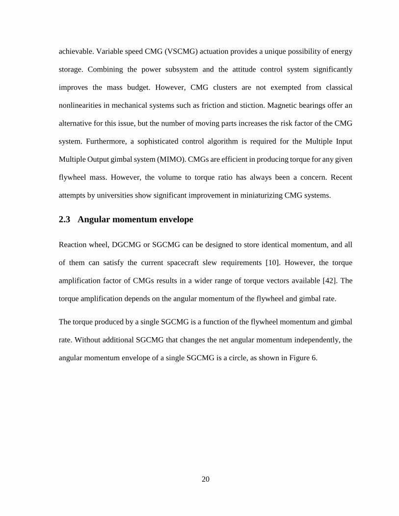
Figure 7 Angular momentum envelope (AME) of pyramid cluster
Figure 7 and Figure 8 show the AME of the pyramid and rooftop cluster, introduced in Table
1, viewed from the same perspective. The orientation of the flywheels was iterated from 0 to
2𝜋 with step angles of 0.1𝜋 for both clusters. The angular momentum vector of each CMG is
added together to plot the net angular momentum vector for the whole cluster. The net angular
momentum of the cluster also depends on the states of individual gimbal angle, 𝛿𝑖, where 𝑖 =
1,2,3 … 𝑛. The AME shows all possible angular momentum vectors for a cluster for any given
gimbal state, 𝛿𝑖.
Figure 7 shows the AME of a pyramid cluster is the closest to a spherical whereas the AME of
the rooftop cluster is elongated in ℎ𝑦 direction. The rooftop cluster is a multiple type

23
configuration, and the elongation is caused by the parallel gimbal axes as shown in the right
column of Table 1.
Figure 8 Angular momentum envelope (AME) of rooftop cluster
The AME of the pyramid cluster is smaller compared to the rooftop, indicating the pyramid
cluster has multiple possible orientations that can achieve similar angular momentum vector.
Even though the number of orientations available for the same angular momentum vector is
greater in the pyramid cluster, the possible number of singularities in the system is also greater.
2.4 Singularities in CMG momentum space
CMG clusters have inherent singularities that are unavoidable and require major attention.
Coordinate singularity is an avoidable type of singularity which occurs when an apparent

24
singularity or discontinuity occurs in one coordinate frame. By virtue of choosing different
coordinate frame this type of singularity can be removed. Coordinate singularities are caused
by choices made during parameterization of CMG cluster due to legacy definition or
convenience. Coordinate singularities can be mitigated by using alternative rotation
formalisms such as Gibbs vector or modified Rodrigues parameters [43]. Singularities directly
associated with the physical system, however, cannot be addressed by changing the reference
frame. Physical singularities associated geometric constraints arise in CMG clusters similar to
a robotic manipulator where rank deficiency of the Jacobian matrix indicates singularities [44].
When a Jacobian matrix is rank deficient, thus non-invertible, classical control laws based on
inverse kinematics fails to generate control input for the system.
The Jacobian of a reaction wheel cluster is predetermined during the design phase and does
not change over time. However, the Jacobian of the CMG cluster is a function of the gimbal
angles and the matrix rank changes over time. When the Jacobian matrix changes with the
gimbal angle and the rank of the Jacobian matrix is two, the CMG cluster is in a singular
direction. CMG cluster would be in a singular plane when the rank of the Jacobian matrix is
one. When the CMG cluster is in a singular direction, no torque is produced by the cluster.
Thus, having additional CMG in the cluster provides an additional null solution as a way to
mitigate the singularity. In reality, when the CMG cluster approaches singularity, the gimbal
rates required to produce torque approaches infinity, which is not practical and thus the system
is in a locked condition smilar to gimbal lock. Therefore steering laws are introduced to
mitigate the singularity issues.
At certain gimbal angles, the angular momentum vectors of each CMG in the cluster can align
parallelly in an arbitrary direction. When all the CMG’s angular momentum is aligned in that

25
particular direction, the cluster is incapable of producing any additional angular momentum
along that vector. This condition is known as the external singularity, where the angular
momentum of the system has reached saturation.
Figure 9 Internal singularity due to momentum vectors aligning [10]
When the momentum vectors of the CMGs align in anti-parallel direction, as shown in Figure
9, the cluster is also unable to produce torque. A simple steering algorithm would deduce that
changing the gimbal rate of CMG with the angular momentum vector in the anti-parallel
direction would not help. This is because there is no way of producing torque without causing
an error in the undesired direction. When some of the CMG opposes the rest of the CMG’s
angular momentum as shown in Figure 9, the system is considered to be in internal singularity.
One way to side-step the singularity issue is by sizing the SGCMGs each with 1ℎ and
restricting the performance to 1ℎ sphere even though the maximum angular momentum is
larger than a sphere of radius 1ℎ. Therefore, limiting the torqueing capability within 1ℎ-sphere
is inefficient and, singularity mitigation must be exercised to utilize all available AME.

26
Differential geometry is used to describe the singular surfaces. Margulies & Auburn, 1978,
and Tokar & and Platonov,1979, were the first to approach the singularity problem using
differential geometry [45] [46]. They have represented the angular momentum as a
differentiable manifold and were able to use surface topology to classify singularity. As a
result, the geometric singularity of SGCMG can be classified into elliptic or hyperbolic.
Kurokawa and Bedrossian provided null motion solutions based on the manifold approach.
Both authors drew a parallel from robotic manipulators and proposed that a singular system
can be reconfigured into a non-singular state by moving in zero-torque producing path [16],
[47]. Singularity definition matrix, S, is expanded from the Taylor Series applied for a change
in momentum that equates to zero, ℎ(Δ) − ℎ(Δ𝑠) = 0 where Δ𝑠 represents the gimbal angles
during singularity.
𝑆 = 𝑁𝑇diag(𝑢𝑇ℎ)𝑁, 𝑁 = 𝑛𝑢𝑙𝑙(𝐴)
The diagonal of the inner product of singular direction, 𝑢, and angular momentum vector, ℎ
and the null basis, N, of the Jacobian matrix, A, determines the type of singularity at any instant
in the system. When the singularity definition matrix only has a trivial solution, the CMG
cluster experiences elliptic singularity, where no null motion can be applied. If the singularity
definition matrix is semi-definite, then the system is in hyperbolic singularity, and there may
be an eigenvector that provides null motion. If the hyperbolic singularity is degenerate, then
the system has no null solution to mitigate the singularity. Non-degenerate hyperbolic
singularity indicates that the system has a continuum of null solutions that are non-singular,
which can be exploited for singularity avoidance [10].

27
2.5 Market survey of commercial-grade CMG
Several models SGCMGs for space applications are currently available commercially-off-the-
self. In early days CMGs were used in large satellites such as MIR and Skylab [24]. However,
the available units for both microsatellites and nanosatellites are limited to a few manufacturers
only. This section provides a market survey for large satellites with mass greater than 500kg
and small satellites with mass less than 500 kg separately.
CMGs were typically used in large space missions; where reaction wheels are not feasible due
to power limitation for the large flywheel and low torque-mass ratio. Table 2 shows a handful
of large CMGs made for space and commercial applications. The torque-mass ratio has been
steadily increasing, especially in CMGs made by Honeywell [48]. The last column in Table 2
represents the DGCMG manufactured for the International Space Station by L-3 Space and
Navigation [49] [50]. Interestingly, the torque-mass ratio of the DGCMG used in ISS is low
compared to other commercially-off-the-shelf, even though the gimbal has no angular
limitation. Naturally, the ratio has suffered from the safety margin and redundancy requirement
that has been imposed on the CMG for ISS [51]. Honeywell’s M225 series has the most torque-
mass ratio with a mass of 54kg and torque of 305.1 Nm [52] [53]. As the mass of a unit
decreases, CMGs from Honeywell lack gimballing freedom. CMG made by Airbus, on the
other hand, has a mass 55.6% of Honeywell’s M50 but produces 60.3% of the torque [54]
[55]. Airbus’s CMG is the lightest of these large CMGs and targets 1-tonne spacecraft with a
promise of less than 10 mrad pointing performance [56]. Resurs-P and Obzor-R are CMGs
made by Command Devices Research Institute (CRDI) in Russia. Both CMGs from CRDI
have five years of service life, which is half that of CMGs from Honeywell [57]. CMG used in
Resurs-P has a similar increment in the gimbal rotation rate of 73.3μrad/s [57].

28
Table 2 Commercially-off-the-shelf CMGs for large satellites
Manufacturer CDRI [57] Airbus
[56]
Honeywell
[54]
L-3
S&N
[50]
Spacecraft\Product Resurs-P Obzor-R 15-45S M50 M95 M160 M225 ISS
Torque [Nm] 37.5 100 45 74.6 128.8 217.0 305.0 258.0
Mass [kg] 49.0 25.6 18.4 33.1 38.6 44.0 54.0 272.0
slew range [deg] 8.6 57.3 - 75.0 129.0 217.0 305.0 ∞
Torque per mass
[Nm/kg] 0.8 3.9 2.5 2.3 3.3 4.9 5.7 1
Clearly, these CMGs presented in Table 2 are unlikely candidates for microsatellite but rather
a pathway for miniaturization. Table 3 summarizes the market survey of smaller CMGs
available off the shelf for small satellites. A lab prototype from the University of Surrey
generated 45mNm torque, without safety margins and redundancy requirements exercised.
SSTL has demonstrated the feasibility of micro-CMG in BILSAT-1 [58] with 20 mNm
torqueing capability. Recently, Honeybee has introduced a single unit CMG that can produce
27.7mNm, which is triple the torque produced by SSTL’s earlier micro-CMG model 10S-E
[59] [60]. SGCMGs from Honeybee, when clustered for maximum performance, produce
172mNm with a peak power consumption of 10W [59]. Russian made CRDI-Mini CMG
produces 1 Nm per SGCMG and weighs about 4.5 kg [57]. CRDI-Mini CMG has the most
torque to mass ratio among the small SGCMGs. Swampsat that carried Vivek’s micro-CMG
developed in the University of Florida has further proven that micro-CMG can be built using
off-the-shelf components within a few iterations of design refinement. These micro-CMG
cluster produced the least torque among other SGCMGs. On the flip side, the CMG from the
University of Florida was only 0.5U in volume and less than 0.5 kg in mass [29] [30]. The
new breakthrough in volume and mass of micro-CMG cluster makes it possible for CubeSats

29
to benefit from high agility CMG based actuation. Veoware is a startup that has also
successfully miniaturized CMG technology. Veoware’s micro-CMG is claimed to be capable
of producing 2 𝑁𝑚𝑠 momenta in two seconds with only 8W. The founders’ claim that
performance with 8W CMG is equivalent to 100W performance of traditional wheels [61].
Honeywell has also made CMGs for micro-to-small satellite categories. Unfortunately, their
mini-CMG failed almost a year after the launch of WorldView-4 and DigitalGlobe is filing for
insurance [62]. The specification and failure reports of Honeywell’s mini-CMG is not
available.
Table 3 Commercially-off-the-shelf CMGs compatible with small satellites.
Manufacturer Spacecraft/
Product
Torque
[mNm]
Mass
[kg]
Power
[W]
Torque/Power
[mNm/W]
Torque/Mass
[Nm/kg]
Veoware [61] - 1000 - 8 125 -
SSTL [58] BILSAT 20 4.0 1.4 15 0.005
SSTL 10S-E 10 1.1 5 2 0.009
HoneyBee
[59] - 172 3.1 8 22 0.056
U of Surrey
[63] - 53 1.2 1.6 33 0.045
CRDI [57] CRDI-
mini 1000 4.5 - - 0.222
U of Florida
[41] SwampSat 0.8 0.4 0.4 2 0.002

30
3 Simulation model of CMG
configurations
A single gimbal control moment gyroscope, SGCMG, based satellite actuator model was built
using Simulink and MATLAB. The CMG model is a core component of the simulation model,
which allows for the investigation of different clusters and steering laws in a modular fashion.
Development of the simulation model is designed such that new investigation in this topic can
be performed by adding new clusters, defined by Jacobian matrices, or novel/hybrid steering
laws.
The simulation model of SGCMG builds on a DC motor model that incorporates motor
constants from the datasheet of the selected DC motor. The SGCMG model is then configured
uniquely about actuator origin for each cluster type based on their angular momentum vector
matrices. This chapter describes all the components of the simulation model and how the
components contribute to the dynamics of the spacecraft.
The control and steering law necessary to derive required gimbal velocity is explained,
followed by three selected trajectories. The three mission profiles are designed to test the
performance of the actuator to justify its usage in a microsatellite application.
3.1 Reference frames
The simulation model of the actuator is defined with respect to an inertial reference frame in
spacecraft. The spacecraft body frame and attitude control system frame overlap with their
origin at the center of mass of the spacecraft. The spacecraft body frame is the reference frame

31
for desired spacecraft attitude and slew rate control. The CMG clusters considered in this thesis
follow various configuration patterns. The clusters’ origin is set to overlap the attitude control
system’s origin without any axial rotation for simplicity. Nevertheless, there is a
transformation matrix between the attitude control system’s origin and individual SGCMG’s
origin for both torque and angular momentum calculations, which is shown in section 3.4.
Since the torque for a unit SGCMG is a function of flywheel momentum, there is one more
transformation matrix between the center of mass of each flywheel and center of mass of
actuator. The development of this matrix is detailed in section 3.4 along with a geometric
interpretation of the available angular momentum and torque generated.
A more realistic approach would involve multiple transformation matrices between attitude
control system frame, spacecraft body frame, including considerations for translational
components. The current model uses special orthogonal matrix, 𝑆𝑂(𝑛) ∈ ℝ𝑛×𝑛, with
determinant +1 as rotation matrices. A special orthogonal matrix has 𝑛 dimension and is a
subset of real number matrix, ℝ, with 𝑛 × 𝑛 dimension. The rotation matrices with 𝑛 = 3 are
used in this study, in place of the full transformation matrix. This approach relaxes the
translational constraints without losing the fidelity of resultant torque.

32
Figure 10 References frame of pyramid cluster and Attitude Control System coincides.
3.2 DC motor model
The most crucial component of an SGCMG is the flywheel since its momentum determines
the maximum torque capability. The first is a fixed speed DC motor directly spinning flywheel,
and second, based on steering law, rotates the flywheel assembly. A permanent magnet direct
current motor has a behaviour described by the following equations.
𝑑𝑖(𝑡)
𝑑𝑡=
1
𝐿[𝑣(𝑡) − 𝑅𝑖(𝑡) − 𝑘𝑒𝑚𝑓𝜔(𝑡)]
(3.1)
𝑑𝜔(𝑡)
𝑑𝑡= −
1
𝐽𝑓 [𝑇(𝑡) + 𝐵𝑚𝜔(𝑡) − 𝑘𝑡𝑖(𝑡)]
(3.2)
For each motor, the input voltage 𝑣(𝑡) depends on the induction 𝐿, resistance of the motor coils
𝑅, and the current as a function of time 𝑖(𝑡), Furthermore the dynamics are affected by the
current flywheel speed, 𝜔(𝑡) and electromotive force constant, 𝑘𝑒𝑚𝑓. The back electromotive
force is generated when the motor spins through the magnetic field. The current consumed by
the coils depends on the input voltage and back EMF voltage. When the two voltages match,

33
the motor velocity is constant and the current consumption is low. The torque generated by
individual SGCMG, 𝜏(𝑡), depends on the angular velocity of the flywheel, angular velocity of
the gimbal and the flywheel’s inertia. The two velocities work together to produce amplified
torque due to the Coriolis effect. The torque from both motor’s acceleration due to the current
and torque constant, 𝑘𝑡, is excluded because it is far smaller than the amplified torque.
The Near-Earth Object Surveillance Satellite’s (NEOSSat) parameters were used in this
simulation study as use case for the satellite. NEOSSat mass of 74 kg and bus size of 1.4 m x
0.8 m x 0.4 m requires 0.03Nm torque per reaction wheel for attitude control [64]. This torque
requirement is imposed on individual SGCMG and motors are selected based on that.
The field of flywheel manufacturing and calibration is sufficiently matured for reaction wheels.
Since these reaction wheels are commercially available, designing an SGCMG based on the
same reaction wheel provides reliability. Therefore, the inertia for the flywheel is constrained
to be similar to the flywheel available in Sparc Lab as the simulation results can be verified
later experimentally. When the selected flywheel operates at a constant speed of 400𝑟𝑎𝑑/𝑠,
the gimbal needs to achieve the angular velocity of 0.47 𝑟𝑎𝑑/𝑠 to provide 0.03Nm.
Faulhaber’s 2224-012SR DC motor was selected to be both the flywheel motor and gimbal
motor since the nominal speed and torque satisfy the torque requirement.

34
Figure 11 Simulated DC motor verification with Faulhaber DC motor 2224 SR
The simulation results for the DC motor is compared with the datasheet provided by the
manufacturer. The basic theoretical validation for the simulation is provided by the matched
no-load speed and no-load current.
35
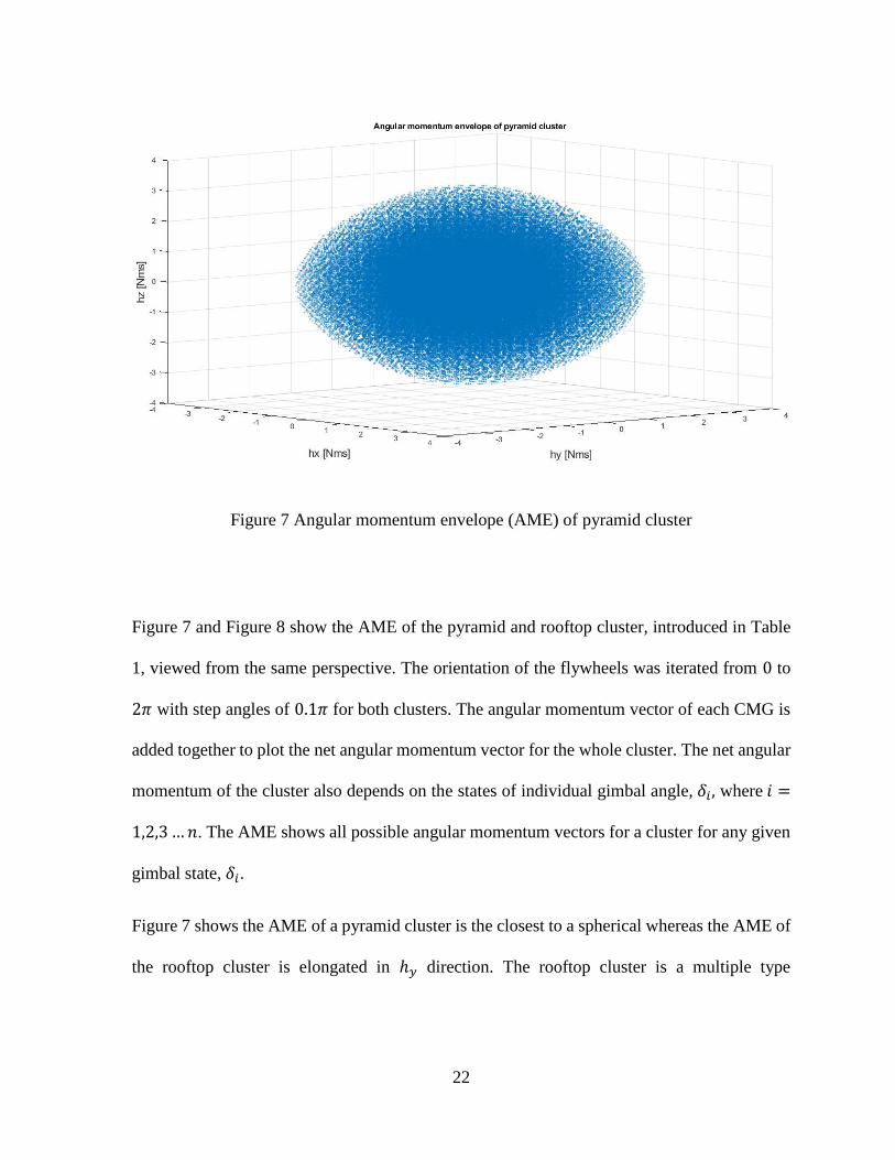
3.3 Single gimbal control moment gyroscope model, SGCMG
A single gimbal CMG, SGCMG, consists of a flywheel assembly (flywheel, flywheel motor,
counterweight and protective casing), and a gimbal. These components are shown in the CAD
model in Figure 12.
Figure 12 Single gimbal control moment gyroscope
The inertias of the flywheel and flywheel assembly are as follows.
𝐽𝑓𝑙𝑦 = [2.99 0 0
0 2.99 00 0 5.76
] ∗ 10−4𝑘𝑔𝑚2,
𝐽𝑓𝑙𝑦𝐴𝑠𝑏𝑚𝑙𝑦 = [7.66 0 0
0 44.92 00 0 44.70
] ∗ 10−5𝑘𝑔𝑚2

36
The flywheel momentum is only concerned with the 𝑧 component of flywheel inertia 𝐽𝑓𝑙𝑦 in
the ℎ axis. The torque generated by gimbal motor, on the other hand, depends on the inertia of
flywheel assembly, including flywheel on the 𝑔 axis. The selection of a gimbal motor and
torque control law depends on the 𝐽𝑓𝑙𝑦𝐴𝑠𝑏𝑚𝑙𝑦.
The angular momentum of the SGCMG, ℎ, and the gimbal axis is always orthogonal. The
torque generated by SGCMG is perpendicular to both the 𝑔 axis and the ℎ axis. Since the
ℎ(𝛿(𝑡)) axis moves with respect to gimbal angle, the torque axis, 𝜏(𝛿(𝑡)), is also a function
of gimbal angle and time-dependent. Figure 13 explains how angular momentum and torque
is represented in terms of gimbal angle, 𝛿(𝑡).
Figure 13 Change in angular momentum vector and torque vector with respect to rotation
about the gimbal axis

37
Figure 14 Angular momentum and torque vector in terms of 𝛿𝑖 at different timestamps
Based on the design of the SGCMG, ℎ(𝛿) = sin(𝛿) and 𝜏(𝛿) = cos(𝛿) =𝑑ℎ(𝛿)
𝑑𝑡. The
geometric derivation of the angular momentum vector and torque vector reaffirms that the
torque vector can be obtained by the differentiation of the angular momentum vector.
3.4 Control moment gyroscope cluster model
The SGCMG units can be assembled in various configurations to suit the need of the mission.
Although three SGCMG is sufficient for 3 axis control, an addition SGCMG provides
necessary null motion for singularity mitigation. Cluster configurations are categorized based
on a plane normal to the gimbal axis. If the normal planes are unique, then the configuration is
categorized as independent type [16]. On the contrary, if there are multiple planes collinear
with each other, then that cluster is classified as multiple type. This thesis compares a
independent-type clusters and a multiple-type cluster. Each cluster, (e.g. Pyramid and
Rooftop), has its characteristic angular momentum envelope and singularities. In spacecraft
control law, the angular momentum of the actuator is used to determine the rigid body motion.

38
The torque matrix is used to translate the individual CMG torques to net actuator torque. The
Jacobian matrix can also be used to map out the singularities existing in the cluster.
Rooftop cluster
A rooftop cluster can be visualized as two planes resting at an angle to each other and make
triangular prism with the ground. An example model in Figure 15 is of multiple type, where
two pairs of SGCMG have a colinear gimbal axis. The angular momentum axes are also
collinear at the initial state. Thus, the angular momentum envelope of this cluster is elongated.
Parallel torque vector, causes rooftop clusters’ angular momentum vector to align and make
the new envelope ellipsoidal.
Figure 15 Rooftop cluster model

39
The ellipsoidal nature of the angular momentum envelope is the result of the aligned flywheels.
Each pair adds to the net angular momentum in parallel in ℎ axis. The angular momentum
matrix, ℎ𝑅𝑓𝑇𝑝, and Jacobian/torque matrix, 𝐴𝑅𝑓𝑇𝑝, are 3 × 4 matrices described in terms of
𝑐𝑎 = cos(𝑎) , 𝑠𝑎 = sin(𝑎) and 𝑎 = skew angle , 𝛿𝑖 = gimbal angle and 𝑖 represent the
SGCMG. The skew angle a, is the angle from xy-plane to the gimbal axis.
ℎ𝑅𝑓𝑇𝑝(𝛿𝑖) = [
−𝑐𝑎𝑐𝛿1 −𝑐𝑎𝑐𝛿2
−𝑠𝛿1 −𝑠𝛿2
𝑠𝑎𝑐𝛿1 𝑠𝑎𝑐𝛿2
𝑐𝑎𝑐𝛿3 𝑐𝑎𝑐𝛿4
𝑠𝛿3 𝑠𝛿4
𝑠𝑎𝑐𝛿3 𝑠𝑎𝑐𝛿4
] [
|ℎ1||ℎ2||ℎ3||ℎ4|
],
𝐴𝑅𝑓𝑇𝑝(𝛿𝑖) = [
𝑐𝑎𝑠𝛿1 𝑐𝑎𝑠𝛿1
−𝑐𝛿1 −𝑐𝛿1
−𝑠𝑎𝑠𝛿1 −𝑠𝑎𝑠𝛿1
−𝑐𝑎𝑠𝛿1 −𝑐𝑎𝑠𝛿1
𝑐𝛿1 𝑐𝛿1
−𝑠𝑎𝑠𝛿1 −𝑠𝑎𝑠𝛿1
]
The initial condition for the gimbal angle shall be chosen such that the torque matrix is full
rank. In the simulation model, initial angles for the SGCMGs are spaced 𝜋
2 𝑟𝑎𝑑.
Pyramid cluster
Pyramid cluster is the most common configuration used in satellites due to spherical angular
momentum envelope. Uniformity in the workspace with sufficient torque allows satellites to
have a wider range of sky available for observation. The angular momentum matrix, ℎ𝑝𝑦, and
Jacobian/torque matrix, 𝐴𝑝𝑦, are 3 × 4 matrices described in terms of 𝑐𝑎 = cos(𝑎) , 𝑠𝑎 =
sin(𝑎) 𝑎𝑛𝑑 𝑎 = 𝑠𝑘𝑒𝑤 𝑎𝑛𝑔𝑙𝑒 , 𝛿𝑖 = 𝑔𝑖𝑚𝑏𝑎𝑙 𝑎𝑛𝑔𝑙𝑒 and 𝑖 represent the SGCMG.
ℎ𝑃𝑦𝑟𝑎𝑚𝑖𝑑(𝛿𝑖) = [
−𝑐𝑎𝑠𝛿1 −𝑐𝛿2
𝑐𝛿1 −𝑐𝑎𝑠𝛿2
𝑠𝑎𝑠𝛿1 𝑠𝑎𝑠𝛿2
𝑐𝑎𝑠𝛿3 𝑐𝛿4
−𝑐𝛿3 𝑐𝑎𝑠𝛿4
𝑠𝑎𝑠𝛿3 𝑠𝑎𝑐𝛿4
] [
|ℎ1||ℎ2||ℎ3||ℎ4|
],

40
𝐴𝑃𝑦𝑟𝑎𝑚𝑖𝑑(𝛿𝑖) = [
−𝑐𝑎𝑐𝛿1 𝑠𝛿2
−𝑠𝛿1 −𝑐𝑎𝑐𝛿2
𝑠𝑎𝑐𝛿1 𝑠𝑎𝑐𝛿2
𝑐𝑎𝑐𝛿3 −𝑠𝛿4
𝑠𝛿3 𝑐𝑎𝑐𝛿4
𝑠𝑎𝑐𝛿3 𝑠𝑎𝑠𝛿4
]
Figure 16 Pyramid cluster model
Actuator Center of mass

41
3.5 Control law
The torque exerted by any actuator is crucial for attitude control of a spacecraft to maintain the
desired slew maneuver. The actuator torque exerted on the spacecraft stops when the gimbal
velocity is zero and if the net torque of the satellite did not add up to zero then it would tumble.
The control law provides a means of calculating the required torque from the actuator. The
torque needed for attitude control for a particular mission is derived using current CMG torque,
𝜏𝑐𝑚𝑔, angular rates, 𝜔𝑖, and spacecraft angular momentum, ℎ𝑠𝑐, of the spacecraft. When a
spacecraft experiences external torques, the actuator must overcome the disturbance, and this
is achieved via the control law. Furthermore, any changes in the trajectory or pointing angle
would also require additional torque. The net angular momentum of a spacecraft with is the
product of the spacecraft inertia, 𝐽𝑠𝑐, and its’ angular rates 𝜔, in addition to internal angular
momentum of SGCMG as shown in equation (3.4). When the spacecraft depends more than
just magnetorquers, the net angular momentum must include moving parts such as the flywheel
of the momentum wheel. For a spacecraft with CMG actuators, the net momentum includes
the angular momentum of flywheel and flywheel assembly, as in equation (3.5).
𝜏𝑐𝑚𝑔 + 𝜔𝑠𝑐 × ℎ𝑠𝑐 = 𝜏𝑒𝑥𝑡 (3.3)
ℎ𝑠𝑐 = 𝐽𝑠𝑐𝜔𝑠𝑐 + ℎ𝑐𝑚𝑔 (3.4)
ℎ𝑐𝑚𝑔 = 𝐽𝑓𝑙𝑦�̇� + 𝐽𝑔𝑖𝑚�̇� (3.5)
The gimbal rate of the SGCMG is kept within an absolute value 1 𝑟𝑎𝑑/𝑠, and the inertia of the
gimbal assembly is relatively low. The angular momentum of the flywheel is two orders of
magnitude greater than the latter. The high spin rate of the flywheel contributes to a large
portion of actuator angular momentum and, consequently, the torque.
42
The substitution of the angular momentum term in equation (3.3) results in the net torque
equation.
𝜏𝑠𝑐 + 𝜔𝑠𝑐 × (𝐽𝑠𝑐𝜔𝑠𝑐 + ℎ𝑐𝑚𝑔) = 𝜏𝑒𝑥𝑡 (3.6)
Propagating the cross product between the terms provides an individual component of the
torque. One must note that the derivative of angular momentum is torque, and thus, the torque
from the equation differentiated (3.4) must equal to the torque in equation (3.6). Here the term
𝐽�̇� from the product rule is always zero since the inertia of the flywheel does not change.
𝜏𝑠𝑐 = 𝐽𝑠𝑐�̇�𝑠𝑐 + 𝐽�̇�𝑐𝜔𝑠𝑐 + ℎ̇𝑐𝑚𝑔 (3.4)
−𝜔𝑠𝑐 × (𝐽𝑠𝑐𝜔𝑠𝑐 + ℎ𝑐𝑚𝑔) + 𝜏𝑒𝑥𝑡 = 𝐽𝑠𝑐�̇�𝑠𝑐 + 𝐽�̇�𝑐𝜔𝑠𝑐 + ℎ̇𝑐𝑚𝑔 (3.3)
𝐽𝑠𝑐�̇�𝑠𝑐 = −ℎ̇𝑐𝑚𝑔 − 𝜔𝑠𝑐 × ℎ𝑐𝑚𝑔 + 𝜏𝑒𝑥𝑡 − 𝜔𝑠𝑐 × 𝐽𝑠𝑐𝜔𝑠𝑐 (3.7)
Collecting the actuator term as input torque,𝜏𝑢, the net torque of the spacecraft can be
simplified into three components, namely the actuator torque, disturbance torque and
spacecraft internal torque.
𝜏𝑢 = −ℎ̇𝑐𝑚𝑔 − 𝜔𝑠𝑐 × ℎ𝑐𝑚𝑔 (3.8)
𝐽𝑠𝑐�̇�𝑠𝑐 = 𝜏𝑢 + 𝜏𝑒𝑥𝑡 − 𝜔𝑠𝑐 × 𝐽𝑠𝑐𝜔𝑠𝑐 (3.9)
The input torque,𝜏𝑢, solely depend on the change in angular momentum. The control law
derived in Eq (3.9) provides the necessary torque to track desired trajectory. This torque
requirement is translated to individual gimbal rate via the steering law which is described in
the next section.
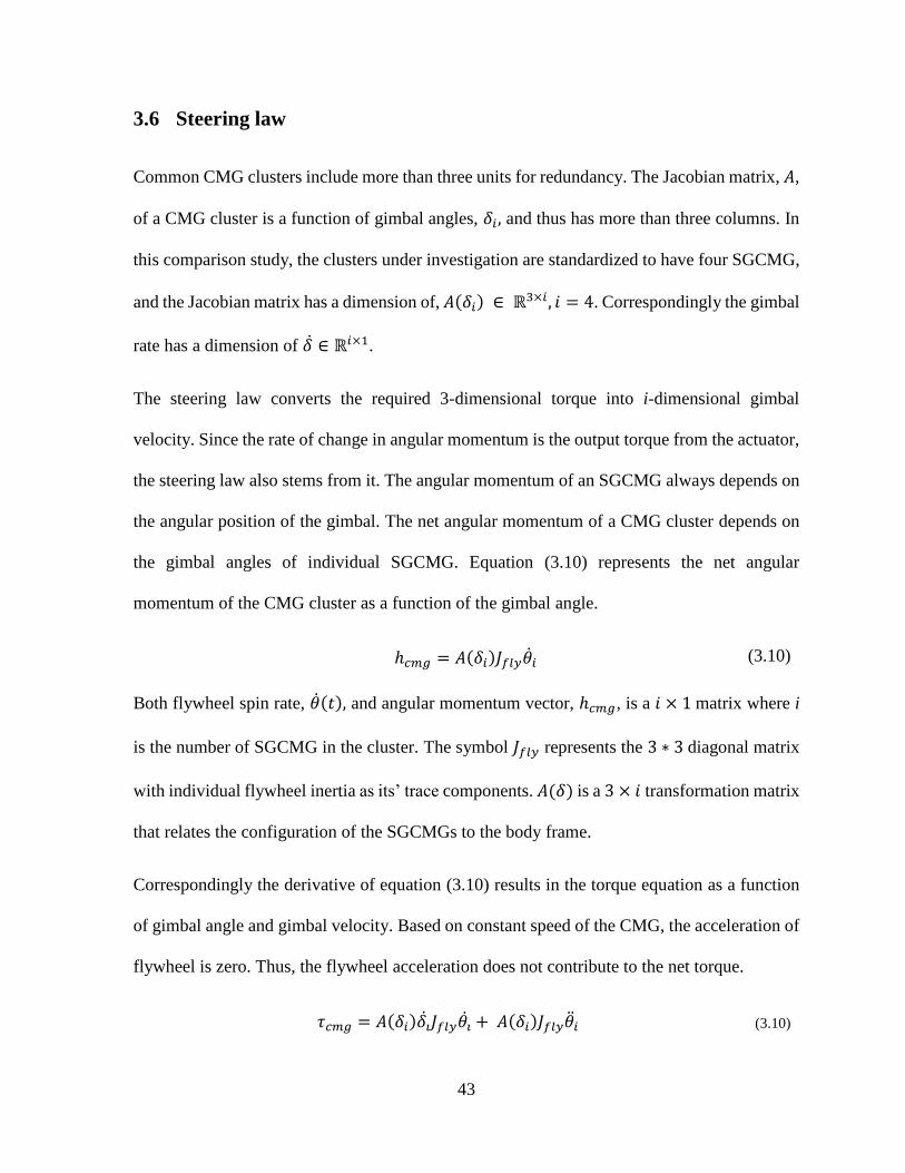
43
3.6 Steering law
Common CMG clusters include more than three units for redundancy. The Jacobian matrix, 𝐴,
of a CMG cluster is a function of gimbal angles, 𝛿𝑖, and thus has more than three columns. In
this comparison study, the clusters under investigation are standardized to have four SGCMG,
and the Jacobian matrix has a dimension of, 𝐴(𝛿𝑖) ∈ ℝ3×𝑖, 𝑖 = 4. Correspondingly the gimbal
rate has a dimension of �̇� ∈ ℝ𝑖×1.
The steering law converts the required 3-dimensional torque into i-dimensional gimbal
velocity. Since the rate of change in angular momentum is the output torque from the actuator,
the steering law also stems from it. The angular momentum of an SGCMG always depends on
the angular position of the gimbal. The net angular momentum of a CMG cluster depends on
the gimbal angles of individual SGCMG. Equation (3.10) represents the net angular
momentum of the CMG cluster as a function of the gimbal angle.
ℎ𝑐𝑚𝑔 = 𝐴(𝛿𝑖)𝐽𝑓𝑙𝑦�̇�𝑖 (3.10)
Both flywheel spin rate, �̇�(𝑡), and angular momentum vector, ℎ𝑐𝑚𝑔, is a 𝑖 × 1 matrix where i
is the number of SGCMG in the cluster. The symbol 𝐽𝑓𝑙𝑦 represents the 3 ∗ 3 diagonal matrix
with individual flywheel inertia as its’ trace components. 𝐴(𝛿) is a 3 × 𝑖 transformation matrix
that relates the configuration of the SGCMGs to the body frame.
Correspondingly the derivative of equation (3.10) results in the torque equation as a function
of gimbal angle and gimbal velocity. Based on constant speed of the CMG, the acceleration of
flywheel is zero. Thus, the flywheel acceleration does not contribute to the net torque.
𝜏𝑐𝑚𝑔 = 𝐴(𝛿𝑖)𝛿�̇�𝐽𝑓𝑙𝑦𝜃�̇� + 𝐴(𝛿𝑖)𝐽𝑓𝑙𝑦�̈�𝑖 (3.10)

44
𝜏𝑐𝑚𝑔 = 𝐴(𝛿𝑖)�̇�𝑖𝐽𝑓𝑙𝑦�̇�𝑖 (3.11)
The first component of the right-hand side of equation (3.11) can be simplified further by
collecting the components that are time-invariant.
𝜏𝑐𝑚𝑔 = 𝐴(𝛿𝑖)�̇�𝑖ℎ𝑐𝑚𝑔 (3.12)
If 𝑖 = 3, then the desired gimbal rate can be obtained from equation (3.12) easily via taking the
inverse of the Jacobian matrix and multiplying with both sides. However, since the 𝑖 > 3 and
Jacobian matrix, 𝐴(𝛿𝑖), is not a square matrix, pseudoinverse methods are employed to derive
the required gimbal rate.
�̇� = −𝐴𝑡(𝐴𝐴𝑡)−1𝜏𝑐𝑚𝑑 + (𝐼−𝐴𝑡(𝐴𝐴𝑡)−1𝐴)𝑘 (3.13)
The solution to the pseudoinverse can be categorized into two parts. The first-term on the right-
hand side is the minimum norm solutions that satisfy the required torque.
𝐴�̇�𝑛𝑜𝑟𝑚 = ℎ̇𝑐𝑚𝑑 = 𝜏𝑐𝑚𝑑 (3.14)
The second term in equation (3.13) is the null motion solution.
𝐴�̇�𝑛𝑢𝑙𝑙 = 0 (3.15)
The extra degrees of freedom from additional SGCMGs can be utilized to avoid singularities
using the second term from the equation. This is known as the null motion of the cluster. During
the null motion the actuator produces no net torque. This is because the torque of individual
CMG units cancels each others’ torque.

45
Moore-Penrose Pseudoinverse
Given the cluster configuration’s dimension, the task of finding desired gimbal rates from
torque command requires pseudoinverse methods. Moore-Penrose pseudoinverse provides a
numerical solution from the torque and null motion.
One solution for the null motion is to have the gimbals velocities such that the resultant torque
is orthogonal amongst them. Triple scalar product measures the orthogonality between three
individual SGCMG torque vectors, which is used to derive the null motion for the fourth
SGCMG.
�̇�𝑁𝑢𝑙𝑙 = [𝑐2 ∙ (𝑐3 × 𝑐4) , −𝑐3 ∙ (𝑐4 × 𝑐1) , 𝑐3 ∙ (𝑐1 × 𝑐2), − 𝑐1 ∙ (𝑐2 × 𝑐3)]𝑡 (3.16)
The Moore-Penrose steering law is analytical and can be summarized as in equation (3.17).
�̇�𝑀𝑃 = 𝐴+ℎ̇𝑐𝑚𝑑 = −𝐴𝑇(𝐴𝐴𝑇)−1ℎ̇𝑐𝑚𝑑 (3.17)
This method of steering law gives an exact solution to the minimum norm problem, which
gives the shortest path to the target without any consideration to mechanical feasibility or
singularity. However, the inherent singularity of the cluster was omitted in the solution.
Singularity robust inverse
Singularity robust inverse is classified as a singularity escape algorithm since the algorithm
aims to recover from passing through the singularity with minimal deviation. The escape is
achieved by introducing a singularity parameter, 𝛼, that increases as the torque vector
approaches the singularity.
𝛼 = 𝛼0𝑒−𝜇𝑚 (3.18)
𝛼0 represents the maximum tolerable error when the cluster is at the singularity. The tolerable
error scales with respect to the singularity measure, 𝑚 = √det(𝐴𝐴𝑇). The rate at which the

46
singularity measure affects the error can be determined by the gain factor, 𝜇. Introducing this
tolerable error in all direction via the steering law results in
�̇�𝑆𝑅𝐼 = 𝐴𝑇(𝐴𝐴𝑇 + 𝛼𝐼3×3)−1ℎ̇𝑐𝑚𝑑 (3.19)
However, one must note that the escape time of the system is deterministic and depends solely
on the selection of the gains, 𝛼0 and 𝜇 [10]. This technique can be further refined to exert
torque only in the axis closest to the singularity by finding it by singular value decomposition
of pseudoinverse of A matrix.
Local gradient
Apart from the singularity escape method that was discussed, another technique that can be
deployed is the singularity avoidance method. The local gradient steering law is an example of
such a method. The singularity avoidance is achieved via the use of a null motion component
of the pseudoinverse.
�̇�𝐿𝐺 = −𝐴𝑇(𝐴𝐴𝑇)−1ℎ̇𝑐𝑚𝑑 + 𝛽(𝐼−𝐴𝑇(𝐴𝐴𝑇)−1𝐴)𝑘 (3.20)
‘𝛽’ here is the singular parameter similar to ‘𝛼’ from singularity robust method. The gradient
search direction ′𝑘′ and other relevant parameters are given below.
𝑘 =𝜕𝑓
𝜕�̇�, 𝑓 = −𝑚2, 𝑚 = √det(𝐴𝐴𝑇)
The gradient search direction helps steer the gimbal opposite to the singularity direction for
individual gimbals. Thus, each motor steers away from the singularity, obeying the null motion
condition. The magnitude of the deviation is derived similarly to the previous method.

47
3.7 Mission profiles
Any satellite must downlink the scientific or other intended data to the ground station to justify
its expensive launch cost. Good communication with ground ensures the mission delivers the
results and possibly maximizes throughput due to a longer downlink window or rapid
acquisition of ground stations. Apart from that, an imaging payload must be protected from the
sun’s radiation to ensure the quality and survivability of the instrument. Therefore, the CMG
actuator must be able to do a sun vector avoidance maneuver. The rule of thumb for the slew
rate for current space missions are within 3o deg/s. The first mission requires a maximum slew
rate of 3.44o deg/s. In short, the two scenarios that a microsatellite needs to satisfy via CMG
clusters are ground communication and sun vector avoidance. The performance of the actuator
is evaluated based on the criteria defined in the next chapter.
Ground communication maneuver
This section describes a communication maneuver where the spacecraft flies above ground-
tower directly.
Since the satellite receiver is in the orbital path’s nadir, the CMG actuator needs to pitch
continuously to maintain the communication link. The resulting Euler commands are such that
the actuator’s performance is focused completely on pitch axis for a single target on the ground.
In Figure 17, the distance, D, between spacecraft and ground target is the minimum Euclidean
distance when the orbital location of the spacecraft and ground target location is known. Earth
central angle, 𝜆, is measured at the center of the Earth from the subsatellite point (SSP) to the
ground target. These two variables and the distance between the Earth’s center and
communication tower, 𝑅𝑒𝑎𝑟𝑡ℎ, used in sine law, provides the nadir angle, 𝜂, which in this case,

48
is the pitch command angle [65]. The time derivative of the nadir angle gives the pitch rate and
acceleration necessary for the maneuver. Figure 18 illustrate the pitch commands for a
microsatellite orbiting around the earth at 600km from the ground; tracking a communication
tower.
Figure 17 Angular relationship between spacecraft, ground target and earth’s center.
The objective of this maneuver is to keep the satellite’s nadir pointing towards the
communication tower. The maneuver begins when the satellite is 5 degrees from the start of
the line of sight and ends 5 degrees before the line of sight end.
Figure 18 ,18 and 19 shows the pitch commands for this mission based on the technique
described above.

49
Figure 18 Pitch command for a spacecraft tracking a communication tower from an altitude of 600km above the ground. Pitching
direction changes at 388 seconds.

50
Figure 19 Pitch rate command for a spacecraft tracking a communication tower from an altitude of 600km above the ground. Change
in pitch rate when satellite crosses ground station at 388 seconds.

51
Figure 20 Pitch acceleration command of ground communicationmission. High slew rates at the begining and end of the manuever is
shown in smaller figure.

52
Sun vector avoidance trajectory
The space environment poses great threats to sensitive scientific payload. Near-Earth Object
Surveillance Satellite (NEOSSat) is a Canadian microsatellite dedicated to detecting and
tracking asteroids and satellites. The search for interior-to-earth-orbit-asteroids requires the
NEOSSat to scan areas near the sun along the ecliptic plane [66]. During the observation phase,
the actuator needs to prevent the microsatellite from moving into an orientation where the sun
rays can damage the optical sensors.
The second scenario under consideration is aimed to provide a test case where the CMG cluster
is maneuvering to avoid sun, in all axes. The trajectory for such a mission can be generated
based on the potential field method or polygon method [67] [68] [69]. Potential field method
assigns high potential value for sun vector, 𝑣𝑠𝑢𝑛, and low potential value for the payload
vector, 𝑣𝑝𝑎𝑦𝑙𝑜𝑎𝑑. The relationship between these vectors is given by the formula,
𝜔𝑠𝑐 =
(𝑣𝑠𝑢𝑛 × (𝑣𝑝𝑎𝑦𝑙𝑜𝑎𝑑 − 𝑣𝑠𝑢𝑛
Δ𝑡 ))
|𝑣𝑠𝑢𝑛 |2
(3.21)
As the pointing angle approaches the sun vector, the potential field equation increases the
angular velocities, making the pointing angle inescapable from the sun vector. Imposing a
negative on this equation causes the opposite reaction where the pointing angle can never reach
the sun vector and consistently avoids it.
The sun vector is a function of the ecliptic longitude which depends on the orbital parameters
of NEOSSat and time. The trajectory is generated starting at midnight of 2nd August 2019 as
an example case and propagated for one full orbit. Using this Julian date, nutation in longitude
and obliquity, and precession of the sun vector in Earth-Centred Inertial frame, ECI, is found.

53
The sun vector is then converted to orbital plane and spacecraft inertial frame subsequently.
The potential field method described by Altaap calculates the spacecraft velocity to reorient
spacecraft towards the sun vector without discontinuity. Using this method, we can align sun
vector and payload vector away from each other in an antiparallel configuration by introducing
a negative sign to Equation (3.21).
Table 4 Keplerian Elements of NEOSSat
Keplerian elements units
Specific angular momentum 53400.2 [𝑘𝑚2/𝑠 ]
Right ascension of ascending node 0.548663 [rad]
Inclination 1.719049 [rad]
Argument of perigee 4.061623 [rad]
Eccentricity 0.0010231
True anomaly [0 − 2𝜋] [rad]
Semi Major Axis 5174 [km]
NEOSSat’s Keplerian elements, as shown in Table 4, were used to model a trajectory for
simulation. The payload vector is at the positive ‘z’ axis when time 𝑡 = 0, and calculated
based on the movement of spacecraft with respect to inertial ACS frame. The potential field
method is employed in the inertial ACS frame, and resulting spacecraft velocity is shown in
Figure 22. The calculated angular velocities are integrated overtime to get NEOSSat trajectory,
as shown in Figure 23. The reoriented payload vector is calculated for each timestep and

54
updated. Figure 21 shows the sun vector and payload vector are approaching an anti-parallel
position in 500 seconds.
Figure 21 Angular difference between sun vector and payload vector in NEOSSat inertial
frame. NEOSSat reorients the optical payload from 90o deg to -90o deg.
The trajectory described in Figure 22 and Figure 23 is for sun vector avoidance maneuver
during data collection phase of NEOSSat.
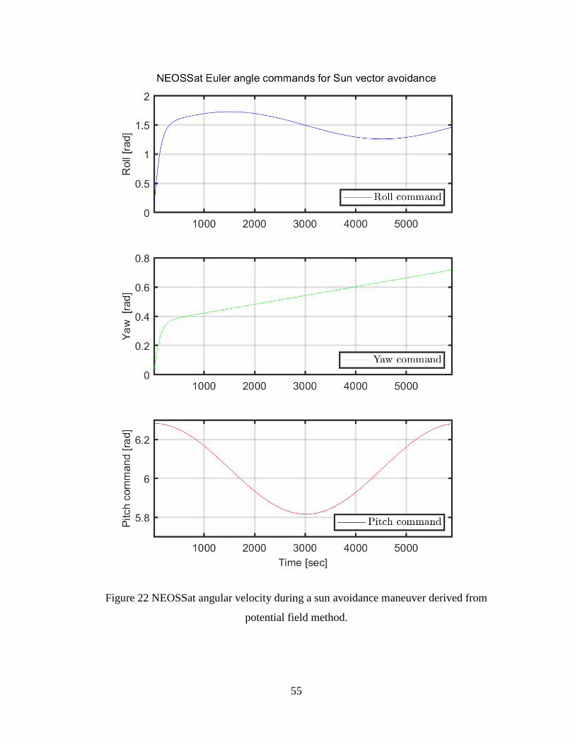
55
Figure 22 NEOSSat angular velocity during a sun avoidance maneuver derived from
potential field method.

56
Figure 23 NEOSSat Euler angles from the integration of angular velocity.
57
The components of CMG clusters and configurations were explained in this chapter. The
control law for finding torque commands and steering law for gimbal rate commands are
discussed. The ground communication trajectory described earlier in this section is an
exemplary path for a satellite orbiting at 600km altitude to downlink scientific data back to the
ground station. The trajectory in the following section is for sun vector avoidance maneuver
for NEOSSat.
Next chapter describes the criterions the CMG clusters have to satisfy while following these
trajectories.

58
4 Simulation results and analysis
Both the downlink quality of the first mission in previous section or the image quality from
second mission greatly depend on the CMG performance. In this chapter, the performance of
the CMG clusters is evaluated in terms of pointing accuracy, jitter and pointing stability of the
imaging platform, which translates into image quality or downlink quality.
4.1 Evaluation criteria
CMG performance in each of the simulation is evaluated in terms of pointing accuracy,
actuator jitter and pointing stability. The CMGs used in Skylab-A have a pointing stability
requirement of 2.9𝑚𝑟𝑎𝑑 in the roll axis and 1.2𝑚𝑟𝑎𝑑 for the other axes [70]. Skylab-A was
36.1m in length, 6.58m in diameter and 83000 kg in mass [21]. Skylab-A has satisfied this
requirement and thus establishes that control using CMG is feasible for large spacecraft.
In terms of small satellites with mass less than 500kg, the required pointing accuracy ranges
from 0.87 − 8.7 𝑚𝑟𝑎𝑑 for telecommunication missions [71]. CubeSats with laser
communication payload requires a pointing accuracy of 1 𝑚𝑟𝑎𝑑 according to trade study by
Dahl [72]. These pointing requirements, as summarized in Table 5, can be the benchmark for
CMG based actuation system for microsatellites.

59
Table 5 Typical pointing accuracy requirements of various satellite classes
Satellite Skylab-A
Medium-sized
telecommunication
satellite
CubeSats
Satellite mass [kg] 83000 <500 <1
Maximum pointing error [mrad] 1.2 – 2.9 0.87-8.7 1.0
Pointing-accuracy is the difference between desired and actual spacecraft pointing direction as
described below in terms of the Euler angles [73].The calculation for pointing accuracy in
pitch, 𝜃error, roll, 𝜙error,and yaw, 𝜓error,is given in following equations.
𝜃error = 𝜃desired − 𝜃result (4.1)
𝜙error = 𝜙desired − 𝜙result (4.2)
𝜓error = 𝜓desired − 𝜓result (4.3)
Jitter is the standard deviation of pointing direction over a specified time window. A jittery
image is contaminated with jagged lines and edges. Thus, it is essential to estimate the jitter to
quantify how much of the image is scientifically valuable in remote sensing case and to
estimate the packet lost during ground communication. Statistically, jitter is the expected value
of the root mean square of the pointing direction over a given time interval. The difference
between pointing direction in ‘𝑖’th axis, 𝜚𝑖, and time-averaged pointing direction, �̅�𝑖 , is
squared to provide the variance in pointing direction. 𝜚𝑖 in the equation is a general term that
can represent each of the Euler angles [73], [74].

60
𝜎𝑖2 = 휀(|𝜚𝑖 − �̅�𝑖|2) (4.4)
The described jitter is measured over a time-window equal to the sensor exposure time of the
imaging system. In a remote sensing mission, for example, the disturbance is the noise factor
in the point spread function of the photons entering CMOS or CCD sensors.
MinXSS-1 is a 3U Cubesat with a miniature X-ray Solar Spectrometer that achieves peak-to-
peak jitter of 0.13 - 0.32 mrad in any axis [75]. Furthermore, quantifying jitter allows the
quality of the image to be quantified and possibly enhanced via post-processing. Ground
images from Beijing-1 small satellites with a mass of 166 kg were post-processed with the
knowledge of jitter in the actuator system to extract geometric properties such as the turning
angles of rivers [76]. Jitter requirements for various classes of satellite is provided in Table 6.
Table 6 Typical jitter requirements of various satellite classes
Satellite JPSS [77] EO-1 [78] MinXSS-1 [75]
Satellite mass [kg] 2540 588 <3
Jitter requirement [mrad] 50 × 10−3 1.5 × 10⁻³ 0.13 - 0.32
Lastly the third parameter for CMG performance evaluation is the pointing stability of the
attitude control system. In a remote sensing mission, a drift in the resultant torque direction of
the CMG cluster would cause poor pointing stability and consequently light streaks in the final
images. Based on the altitude of telecommunication satellite, a poor pointing stability can result
in lost communication or alternatively require sophisticated ground stations to retrieve data
packets with minimal loss. Thus, the stability of the spacecraft is an important metric to
evaluate CMG clusters’ performance.

61
Stability is relative to time, in the sense that within the time interval of few milliseconds, the
spacecraft can be relatively stable, but for time intervals over tens of seconds, the spacecraft
might be drifting. Therefore, this thesis considers two different time intervals for stability
calculations, 2s and 100s. The former provides stability criteria for exposure time of the
imaging payload and the latter for continuous imaging duration of the spacecraft.
The formulation for spacecraft pointing stability, 𝜍𝑖, depends on the variance of jitter, 𝜎𝑖, in
the pointing axis, i. The value of n represents the number of jitter measurements made during
the integration period. The average of the jitter depicts the trends in pointing direction; and
taking the square root of the average of squared jitter provides the standard deviation of the
spacecraft stability [73], [74].
𝜍𝑖2 = (∑ 𝜎𝑖
2
𝑛
0
) /𝑛 (4.5)

62
4.2 CMG performance in Ground Communication Maneuver
This section presents the simulation results for a single-axis ground communication maneuver
of a spacecraft orbiting the earth at an altitude of 600km. The chart below is repeated from
Figure 18 in section 3.7.1. It illustrates a section of ground communication maneuver that is of
most interest. The spacecraft is shifting it’s pitching direction from counter clockwise to
clockwise as it flies over the ground communication tower.
Figure 24 Pitch angle command for maintaining communication with ground tower during
the inflection point in spacecraft flyby.

63
Pointing Accuracies in ground communication manuever
The following figures and tables compare the pointing accuracy of a spacecraft during the
ground communication maneuver described in 3.7.1. Both the pyramid and rooftop clusters
completed the maneuver with a maximum pointing error of 23 mrad in the yaw axis. The
overall pointing accuracy of both pyramid, in Figure 25, and rooftop, in Figure 26, does not
satisfy the pointing accuracy requirement for radio frequency communication, 8.7 mrad, nor
optical communication, 1 mrad, due to the pointing error in the yaw axis. The spacecraft
receives no tracking commands for the yaw and roll axis based on the scenario presented in
section 3.7.1. Active tracking for this maneuver is only in the pitch axis, as shown in Figure
24. Local gradient and Moore-Penrose steering law have overlapping performance in all axis
for pyramid cluster as shown in Figure 25. The local gradient method results in a 16.80% larger
pointing error in the yaw axis when used in conjunction with the pyramid cluster. The pointing
error in yaw is due to the small momentum space in angular momentum envelope. All the
steering laws performed similarly when utilized on the rooftop cluster as shown in Figure 26.
Table 7 Largest pointing error in ground communication maneuver for pyramid and rooftop
cluster for all steering laws
Scenario 1 Pyramid Rooftop
Pointing error
[𝑚𝑟𝑎𝑑] Roll, 𝜙
Pitch, 𝜃
Yaw, 𝜓
Roll, 𝜙
Pitch, 𝜃
Yaw, 𝜓
Moore-Penrose 0.8072 3.411 23.21 −1.213 3.346 23.21
Local Gradient 0.8072 3.983 23.21 −1.213 3.346 23.21
Singularity
Robust Inverse 0.8072 3.411 23.21 −1.213 3.346 23.21

64
Figure 25 Pointing error during flyby over the ground tower with pyramid cluster. Moore Penrose, MP, Singularity Robust Inverse,
SRI, and Local Gradient, LG, have overlapping performance in individual axis.

65
Figure 26 Pointing error during flyby over the ground tower with rooftop cluster. Moore Penrose, MP, Singularity Robust Inverse,
SRI, and Local Gradient, LG, have overlapping performance in individual axis.

66
Jitters in ground communication manuever
The slew rate of the spacecraft increases as it approaches and draws away from the ground
station. The jitter in both pyramid and rooftop increases as the spacecraft’s slew rate increases
in either direction. During the direction change at 388s as seen in Figure 24, however, the jitter
decreases. In Figure 27, the pyramid cluster reaches a maximum of 0.2343 mrad peak to peak
jitter at 447.5 seconds in the yaw axis with Singularity Robust Inverse steering law. The rooftop
cluster has maximum jitter near the same region, as seen in Figure 28, with a magnitude 0.085
% of the pyramid cluster. A jitter of 0.23 mrad results from the pyramid cluster during a slew
rate of 9.2 mrad/s. All the steering laws performed equally; except Singularity Robust Inverse,
which performed slightly worse in the yaw axis.
The jitter performance of rooftop with local gradient method (0.2349mrad) and pyramid cluster
with singularity-robust inverse (0.2343mrad), falls within MinXSS-1’s jitter requirement of
0.13 - 0.32 mrad. Since the worst performing pairs from rooftop and pyramid meets the jitter
requirement for a remote sensing mission all possible pairs has satisfied the requirement.
Table 8 Largest jitter for ground communication maneuver for pyramid and rooftop cluster
for all steering laws
Scenario 1 Pyramid Rooftop
Jitter [𝜇𝑟𝑎𝑑] Roll, 𝜙 Pitch, 𝜃 Yaw, 𝜓 Roll, 𝜙 Pitch, 𝜃 Yaw, 𝜓
Moore-Penrose 4.212 19.64 232.9 7.743 18.81 233.1 Local Gradient 4.088 22.86 233.8 7.743 18.81 234.9
Singularity
Robust Inverse 4.236 19.73 234.3 7.743 18.81 233.7
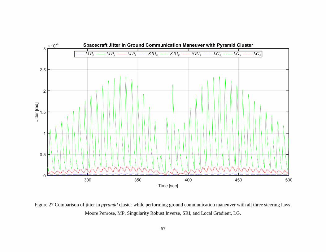
67
Figure 27 Comparison of jitter in pyramid cluster while performing ground communication maneuver with all three steering laws;
Moore Penrose, MP, Singularity Robust Inverse, SRI, and Local Gradient, LG.

68
Figure 28 Comparison of jitter in rooftop cluster while performing ground communication maneuver with all three steering laws;
Moore Penrose, MP, Singularity Robust Inverse, SRI, and Local Gradient, LG.

69
Pointing Stabilities in ground communication manuever
For the purpose of this study the pointing stability is defined as the standard deviation of jitter.
As such the general trend in jitter continues in pointing stability. The error in pointing stability
for both the pyramid and the rooftop cluster is greater during high slew rate when measured
over a 2-second interval and 100-second interval. The instability minimizes during the
inflection point in pitch rotation. The spacecraft satisfies the pointing stability requirement of
2.9 mrad for roll and 1.2 mrad for yaw and pitch throughout the maneuver and during the
direction flip in pitch rotation. The analysis for 2-second integration interval is given next
followed by the 100-second integration interval.
Pyramid cluster has peak-to-peak pointing stability of 78.43 μrad using the local gradient
method, and the rooftop cluster has 78.63 𝜇𝑟𝑎𝑑 via singularity robust inverse steering law in
the yaw axis. For example, a typical remote sensing mission like the Skylab-A’s pointing
stability requirement is 2.9mrad, for roll axis, and 1.2mrad, for yaw and pitch axis, for a one-
second interval. These values are not directly comparable with simulation results due to various
factors including the choice of integration interval and exemption of nonlinearities in the
simulation such as wheel imbalance and friction. However, the simulation results are two
orders of magnitude better and therefore CMGs in this study meet the requirements of a remote
sensing mission. One can notice a cyclic disturbance present in Figure 29 and Figure 30 for
the pointing stability of the imaging platform, both in the pyramid and rooftop clusters.

70
Figure 29 Spacecraft pointing-stability over a 2-second interval; Comparing all steering law with pyramid cluster for ground
communication maneuver.

71
Figure 30 Spacecraft pointing-stability over a 2-second interval; Comparing all steering law with rooftop cluster for ground
communication maneuver

72
Table 9 Pointing stability for two-second integration window during ground communication
maneuver for pyramid and rooftop cluster for all steering laws
Scenario 1 Pyramid Rooftop
Pointing stability (2s)
[𝜇𝑟𝑎𝑑] Roll, 𝜙
Pitch, 𝜃
Yaw, 𝜓
Roll, 𝜙
Pitch, 𝜃
Yaw, 𝜓
Moore-Penrose 0.63 3.67 77.79 1.77 3.39 77.85 Local Gradient 0.58 4.26 78.27 1.77 3.41 78.63
Singularity Robust
Inverse 0.63 3.71 78.43 1.77 3.43 78.15
The pointing stability of spacecraft over a 100-second interval gradually increases and reaches
a maximum of 61.25 × 10⁻³ mrad with local gradient method and 61.21 × 10⁻³ mrad via
singularity robust inverse method for pyramid and rooftop respectively. Both clusters’ pointing
instability gradually increases and reaches a peak around 350-second mark and decreases after
a 500-second mark. Between these two time-stamps, the spacecraft has an absolute slew rate
higher than 5.2 mrad/s and acceleration ranging from −0.052 mrad/s2 at 350 seconds to
52.36 𝜇𝑟𝑎𝑑/𝑠2 at 500 seconds.
Table 10 Pointing stability for hundred-second integration window during ground
communication maneuver for pyramid and rooftop cluster for all steering laws
Scenario 1 Pyramid Rooftop
Pointing stability (100s)
[𝜇𝑟𝑎𝑑] Roll, 𝜙
Pitch, 𝜃
Yaw, 𝜓
Roll, 𝜙
Pitch, 𝜃
Yaw, 𝜓
Moore-Penrose 0.99 4.58 61.11 1.86 4.36 61.15 Local Gradient 0.99 5.32 61.25 1.86 4.36 61.21
Singularity Robust
Inverse 0.99 4.58 61.14 1.86 4.36 61.31

73
Figure 31 Comparison of Moore-Penrose, MP, Singularity Robust Inverse, SRI, and Local Gradient method, LG, with pyramid cluster
for scenario ground communication maneuver in terms of pointing stability

74
Figure 32 Comparison of Moore-Penrose, MP, Singularity Robust Inverse, SRI, and Local Gradient method, LG, with rooftop cluster
for scenario ground communication maneuver in terms of pointing stability

75
The rooftop cluster exhibits similar and stable pitch axis for all the individual steering law
employed. However, the instability in the roll axis for rooftop is double that of the pyramid
cluster. The instability in the yaw axis is comparable for both clusters regardless of the steering
law used for the mission.
4.3 CMG performance in sun vector avoidance maneuver
In this section, the simulation results for the sun vector avoidance maneuver for NEOSSat is
presented; for an ideal CMG cluster without wheel imbalance and friction, as described in 3.4.
The CMG clusters’ performance from 2900 seconds to 4000 seconds has the largest pointing
errors and therefore of high interest for the analysis. The quaternion commands, commonly
used to prevent singularities, during this particular portion of maneuver is shown in Figure 33.
Figure 33 NEOSSat quaternion commands for sun vector avoidance maneuver.
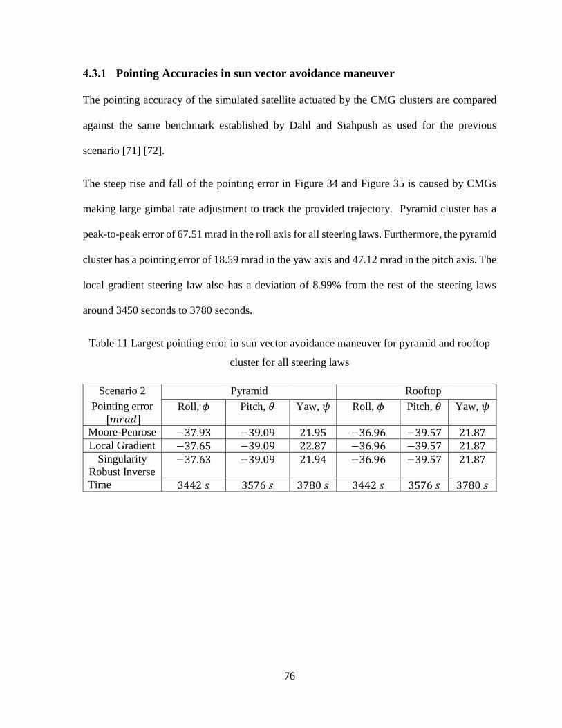
76
Pointing Accuracies in sun vector avoidance maneuver
The pointing accuracy of the simulated satellite actuated by the CMG clusters are compared
against the same benchmark established by Dahl and Siahpush as used for the previous
scenario [71] [72].
The steep rise and fall of the pointing error in Figure 34 and Figure 35 is caused by CMGs
making large gimbal rate adjustment to track the provided trajectory. Pyramid cluster has a
peak-to-peak error of 67.51 mrad in the roll axis for all steering laws. Furthermore, the pyramid
cluster has a pointing error of 18.59 mrad in the yaw axis and 47.12 mrad in the pitch axis. The
local gradient steering law also has a deviation of 8.99% from the rest of the steering laws
around 3450 seconds to 3780 seconds.
Table 11 Largest pointing error in sun vector avoidance maneuver for pyramid and rooftop
cluster for all steering laws
Scenario 2 Pyramid Rooftop
Pointing error
[𝑚𝑟𝑎𝑑] Roll, 𝜙
Pitch, 𝜃
Yaw, 𝜓
Roll, 𝜙
Pitch, 𝜃
Yaw, 𝜓
Moore-Penrose −37.93 −39.09 21.95 −36.96 −39.57 21.87 Local Gradient −37.65 −39.09 22.87 −36.96 −39.57 21.87
Singularity
Robust Inverse −37.63 −39.09 21.94 −36.96 −39.57 21.87
Time 3442 𝑠 3576 𝑠 3780 𝑠 3442 𝑠 3576 𝑠 3780 𝑠
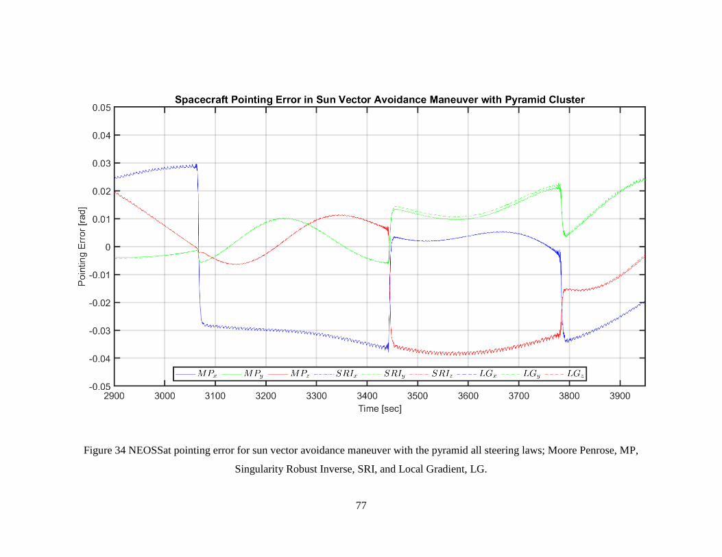
77
Figure 34 NEOSSat pointing error for sun vector avoidance maneuver with the pyramid all steering laws; Moore Penrose, MP,
Singularity Robust Inverse, SRI, and Local Gradient, LG.

78
Figure 35 NEOSSat pointing error for sun vector avoidance maneuver with the rooftop cluster for all steering laws; Moore Penrose,
MP, Singularity Robust Inverse, SRI, and Local Gradient, LG.

79
Rooftop cluster, on the other hand, has similar pointing errors in all three axes. In the roll axis,
a peak-to-peak pointing error of 56.90 mrad is present. Yaw axis and pitch axis have peak-to-
peak pointing errors of 19.76 mrad or and 45.59 mrad, respectively. For rooftop configuration
all the steering laws performed equally and no deviation is present.
Jitters in sun vector avoidance maneuver
Unlike ground communication mission, the jitter in sun vector avoidance maneuver has
isolated jumps caused by the large gimbal rate change reflected in the sudden rise and fall of
pointing error. The most significant jitter experienced by NEOSSat with the pyramid cluster is
8.28mrad at 3068 seconds in the roll axis. Rooftop cluster causes a jitter of 8.76mrad at the
same timestep. Furthermore, both pyramid and rooftop clusters have a base jitter ranging from
0.0864 mrad − 0.591 mrad. The base jitter of both clusters falls within the established jitter
requirement. The jitter spike is present in both clusters’ performance at 3068 seconds because
of the change in pointing angle command at that instant. Furthermore, the magnitude of base
jitter in different axis changes after each jitter spike indicating the most significant torqueing
axis.
Table 12 Largest jitter in sun vector avoidance maneuver for pyramid and rooftop cluster for
all steering laws
Scenario 2 Pyramid Rooftop
Jitter [𝑚𝑟𝑎𝑑] Roll, 𝜙 Pitch, 𝜃 Yaw, 𝜓 Roll, 𝜙 Pitch, 𝜃 Yaw, 𝜓
Moore-Penrose 8.279 5.302 2.171 8.393 5.451 2.346 Local Gradient 8.275 5.290 2.241 8.393 5.448 2.345
Singularity
Robust Inverse 8.226 5.026 2.052 8.756 5.363 2.303
Time 3068 𝑠 3445 𝑠 3445 𝑠 3068 𝑠 3445 𝑠 3445 𝑠
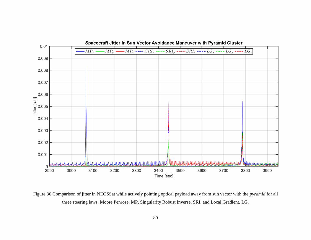
80
Figure 36 Comparison of jitter in NEOSSat while actively pointing optical payload away from sun vector with the pyramid for all
three steering laws; Moore Penrose, MP, Singularity Robust Inverse, SRI, and Local Gradient, LG.

81
Figure 37 Comparison of jitter in NEOSSat while actively pointing optical payload away from sun vector with the rooftop for all three
steering laws; Moore Penrose, MP, Singularity Robust Inverse, SRI, and Local Gradient, LG.

82
Nevertheless, the jitter spike in the yaw axis is within MinXSS-1’s jitter requirement of 3.23
mrad as described in section 4.1. The largest base jitter is observed in the roll axis and is below
the lower limit of the jitter requirement, 1.31mrad. Avoiding data collection during the known
jitter spike during maneuvering ensures the jitter requirement is met during imaging period in
remote sensing satellites.
Pointing Stabilities in sun vector avoidance maneuver
The pointing stability of NEOSSat during sun vector avoidance maneuver reflects the jitter
experienced by the spacecraft, especially at 3068th second. The 2-second integration interval
pointing stability at that instant is the largest at 1.85mrad for the pyramid cluster using the
local gradient method. All three jitter jumps observed in the previous section caused pointing
stability to vary between 1.37 mrad − 1.85 mrad whereas the jitter jumps were between
5.40 mrad − 8.28 mrad. Similarly, the rooftop cluster’s pointing stability varies from
1.32 mrad − 1.99 mrad due to jitter jumps from 5.27 mrad − 8.76 mrad. Both pyramid and
rooftop clusters were only able to satisfy the pointing stability requirement in yaw (1.20 mrad)
and roll (2.90 mrad) axis. The singularity robust inverse steering law produced pointing
stability of 1.23 mrad for pyramid cluster which is 3.25% shy of satisfying the pointing
stability requirement of 1.20 mrad. Similarly, singularity robust inverse was also best for
rooftop cluster in pitch axis but shy to satisfy the requirement by 4.90%. The base pointing
instability is well below the requirements for both clusters with any steering law

83
Figure 38 Pointing stability of NEOSSat with the pyramid cluster for the 2-second interval during sun vector avoidance maneuver

84
Figure 39 Pointing stability of NEOSSat with the rooftop cluster for the 2-second interval during sun vector avoidance maneuver.

85
between 44.55 × 10⁻³ − 65.29 × 10⁻² mrad. Table 13 summarizes the performance of the
steering laws and CMG clusters for the 2 second integration interval.
Table 13 Pointing stability for two-second integration window while sun vector avoidance
maneuver for pyramid and rooftop cluster for all steering laws
Scenario 2 Pyramid Rooftop
Pointing stability (2s)
[𝑚𝑟𝑎𝑑] Roll, 𝜙
Pitch, 𝜃
Yaw, 𝜓
Roll, 𝜙
Pitch, 𝜃
Yaw, 𝜓
Moore-Penrose 1.845 1.284 0.4756 1.853 1.310 0.5033 Local Gradient 1.846 1.279 0.4847 1.853 1.299 0.5033
Singularity Robust
Inverse 1.803 1.234 0.4361 1.993 1.259 0.4948
Time [sec] 3068 3444 3444 3068 3444 3444
A 100-second interval pointing stability reflects the overall stability of the spacecraft during
the maneuver. In the sun vector avoidance maneuver, the roll axis stability was severely
affected compared to other axes due to the largest jitter is at the 3068th second. The worst
pointing stability integrated over 100-second among both clusters and any steering law is
1.19 mrad in roll axis of the rooftop cluster with Moore-Penrose and local gradient. The latter
is within the pointing stability requirement of Skylab-A.
In the rooftop cluster, both Moore-Penrose and local gradient resulted in 89.59 × 10⁻² mrad
pointing instability for pitch axis. Singularity robust inverse method was the best in pitch and
yaw axis in both clusters. Meanwhile, Moore-Penrose and the local gradient method equally
outperform Singularity robust inverse in the roll axis of the rooftop cluster. Gimbal rate
commands by local gradient steering law caused the yaw axis of NEOSSat to be 8.5% and
1.5% less stable in the pyramid and rooftop cluster compared to the singularity robust method.
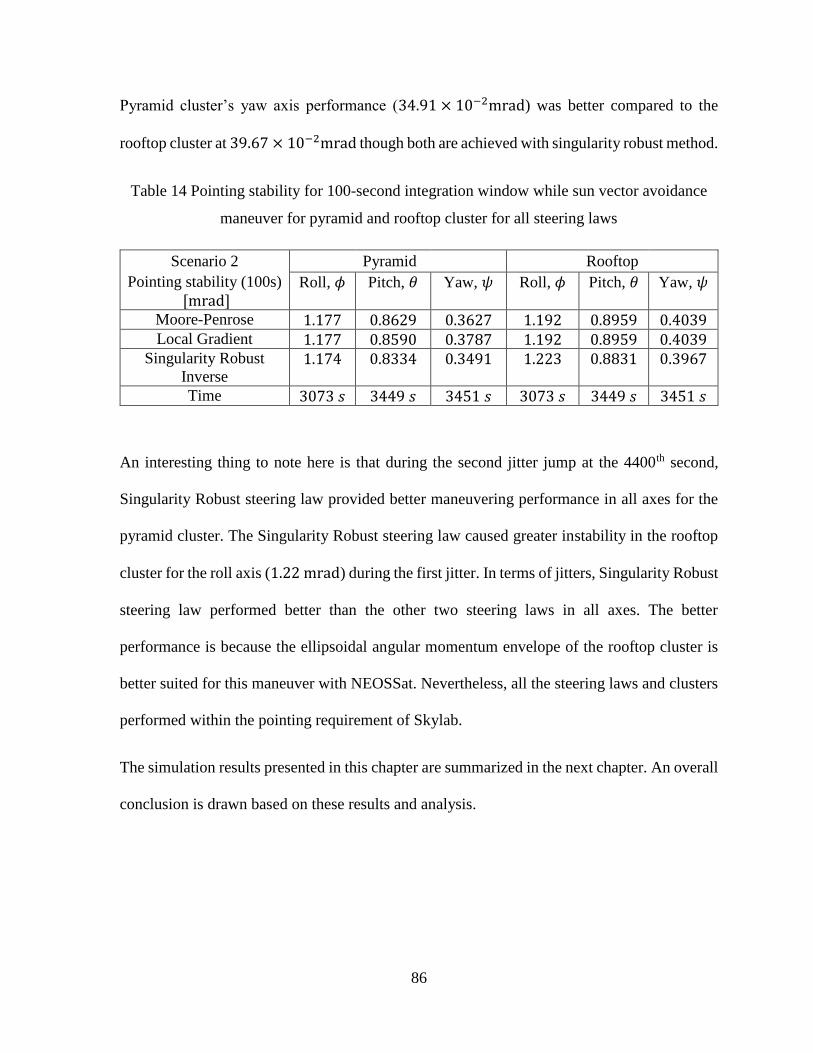
86
Pyramid cluster’s yaw axis performance (34.91 × 10⁻²mrad) was better compared to the
rooftop cluster at 39.67 × 10⁻²mrad though both are achieved with singularity robust method.
Table 14 Pointing stability for 100-second integration window while sun vector avoidance
maneuver for pyramid and rooftop cluster for all steering laws
Scenario 2 Pyramid Rooftop
Pointing stability (100s)
[mrad] Roll, 𝜙
Pitch, 𝜃
Yaw, 𝜓
Roll, 𝜙
Pitch, 𝜃
Yaw, 𝜓
Moore-Penrose 1.177 0.8629 0.3627 1.192 0.8959 0.4039 Local Gradient 1.177 0.8590 0.3787 1.192 0.8959 0.4039
Singularity Robust
Inverse 1.174 0.8334 0.3491 1.223 0.8831 0.3967
Time 3073 𝑠 3449 𝑠 3451 𝑠 3073 𝑠 3449 𝑠 3451 𝑠
An interesting thing to note here is that during the second jitter jump at the 4400th second,
Singularity Robust steering law provided better maneuvering performance in all axes for the
pyramid cluster. The Singularity Robust steering law caused greater instability in the rooftop
cluster for the roll axis (1.22 mrad) during the first jitter. In terms of jitters, Singularity Robust
steering law performed better than the other two steering laws in all axes. The better
performance is because the ellipsoidal angular momentum envelope of the rooftop cluster is
better suited for this maneuver with NEOSSat. Nevertheless, all the steering laws and clusters
performed within the pointing requirement of Skylab.
The simulation results presented in this chapter are summarized in the next chapter. An overall
conclusion is drawn based on these results and analysis.

87
Figure 40 Pointing stability of NEOSSat with the pyramid cluster for the 100-second interval during sun vector avoidance maneuver.
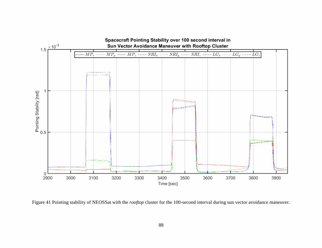
88
Figure 41 Pointing stability of NEOSSat with the rooftop cluster for the 100-second interval during sun vector avoidance maneuver.

89
5 Final Remarks
Low-cost remote sensing microsatellites are capable of providing rapid ground images with
adequate quality for disaster relief missions and military use. Thus, control moment gyroscope
(CMG) clusters are proposed for the rapid slews necessary for responsive remote sensing
systems. Though CMGs are used in many large space missions, their usage in microsatellites
is uncommon due to the mechanical and control complexity of CMG systems. In this research
two types of CMG clusters each with three different steering laws are compared to provide a
baseline to make design decisions and reasonably allocate resources.
Past missions with CMGs have been studied for their performance, which is later used as a
benchmark for microsatellite study. The type of CMGs and their specifications are well
documented in the literature. Since steering laws are computationally expensive, in the early
decades, numerous mathematical adaptations were employed to simplify ACS. The general
rule for CMG designs is to have CMG configurations with simple torque matrix and the
Jacobian to be equal to transpose of torque matrix. Consequently, legacy steering laws are not
applicable for microsatellites.
A CMG based satellite has high torque range, which translates into a large slew rate and
consequently rapid target acquisition. The high torque results from the torque amplification
factor where stored angular momentum is gimballed via low current gimbal motor.
Subsequently, the power consumption of CMG is low for high torque outputs. The high torque
to power consumption ratio makes CMGs the most power-efficient torqueing system.

90
In order to size a CMG system for microsatellite usage, one must study the angular momentum
envelope and the singularities of a cluster. Characteristics of the angular momentum envelope
for the pyramid rooftop cluster are discussed. An explanation of coordinate singularities and
physical singularities of CMG clusters are provided in 2.4. A comprehensive market survey
with off-the-shelf products and academic prototypes are included because the CMG market for
space industry is relatively young, especially for microsatellites.
A simulation platform via Matlab and Simulink is developed to provide a thorough
comparative study of CMG actuators. The development of a generic tool with modular
architecture provides flexibility to select cluster configuration, steering law and satellite
trajectory. In this study, pyramid and rooftop clusters were studied with steering laws such as
Moore Penrose, Singularity Robust Inverse and Local Gradient method for ground
communication maneuver and sun vector avoidance maneuver. The simulation model
incorporates a CMG cluster with 4 SGCMGs which are configured in pyramid or rooftop
form. The torque necessary for a satellite to track a trajectory is obtained using the Euler
equation. The calculated torque is translated into individual gimbal rates via different steering
laws. Steering laws from two types of singularity mitigation techniques, namely Singularity
Robust Inverse and Local Gradient were compared alongside the analytical Moore-Penrose
steering law. Singularity Robust inverse steering law adds tolerable error in gimbal rates that
aids the CMGs to pass through singularities and recover. Local gradient method, on the other
hand, steers the gimbals away from singularities at all times. These scenarios are compared
based on their performance in ground communication and in sun vector avoidance.
The performances of CMG clusters and steering laws were evaluated based on 3 categories:
pointing error, platform jitter, and pointing stability (2-second and 100-second integration

91
window). For the ground communication scenario, a spacecraft orbiting at 600km altitude had
to track pitch commands actively while the other axes were set to zero. One must note that the
requirement for the evaluation criterias are derived from past missions which uses different
actuators. The requirements are chosen to provide a baseline for comparing CMG performance
with other types of spacecraft actuators.
Table 15 Best performing combination for each evaluation criteria on spacecraft’s principle
axes for ground communication manuever. Possible combinations of CMG cluster: Pyramid
(Py) or Rooftop (Rf) with Steering Laws: Moore-Penrose Pseudoinverse (MP) or Singularity
Robust Inverse (SRI) or Local Gradient (LG).
Communication
maneuver [mrad]
Roll,
𝜙
Pitch,
𝜃
Yaw,
𝜓
Pointing accuracy Py Any 0.81 Rf Any 3.3 Any Any 23
Jitter Py LG 0.0041 Rf Any 0.019 Py MP 0.23
Pointing Stability (2s) Py LG 0.00058 Rf MP 0.0034 Py MP 0.078
Pointing Stability
(100s)
Py Any 0.00099 Rf Any 0.0044 Py MP 0.061
In ground communication maneuver, the pyramid cluster performing well in both roll and yaw
axes. Rooftop cluster performed 1.9% better in pitch axis than pyramid cluster for all steering
law. However, the rooftop cluster suffered more roll error than the pyramid cluster according
to Table 7. Both clusters did poorly in the yaw axis, where the errors were ten times more than
pointing accuracy requirements of Skylab-A. However, pyramid cluster with Moore-Penrose
pseudoinverse steering law performed relatively better in yaw axis. Altough the command was
only in pitch axis the coupled nature of a CMG system causes other axes to suffer.

92
Furthermore, all steering laws performed almost equally for this criterion, though the local
gradient method provided less pitching error for the pyramid cluster. Both clusters satisfied the
jitter requirement for the ground communication manuever. We can note that the local gradient
method produced more jitter compared to other steering laws for pitch axis with pyramid
cluster and yaw axis with rooftop cluster. In contrast, the local gradient method managed to
stabilize the yaw axis jitter for the rooftop cluster as shown in Table 8. Pointing stabilities of
both 2-second and 100-second integration interval benefits from pyramid cluster, as shown in
Table 15.
Table 16 Best performing combination for each evaluation criteria on spacecraft’s principle
axes for sun vector avoidance manuever. Possible combinations of CMG cluster: Pyramid
(Py) or Rooftop (Rf) with Steering Law: Moore-Penrose Pseudoinverse (MP) or Singularity
Robust Inverse (SRI) or Local Gradient (LG).
Sun-vector avoidance
maneuver [mrad]
Roll,
𝜙
Pitch,
𝜃
Yaw,
𝜓
Pointing accuracy Rf Any 37 Py Any 39 Rf Any 22
Jitter Py SRI 8.2 Py SRI 5.0 Py SRI 2.1
Pointing Stability (2s) Py SRI 1.8 Py SRI 1.2 Py SRI 0.44
Pointing Stability (100s) Rf SRI 1.2 Py SRI 0.83 Py SRI 0.35
The simulation results for sun vector avoidance maneuver reveals that neither cluster was able
to meet the pointing accuracy requirement with any steering law. The jitter jumps caused by
sudden change in tracking command caused the roll and pitch axis not meet the jitter
requirement. The yaw axis’s jitter performance was satisfactory for both clusters. If the jitter
jumps were to be excluded via better trajectory generation, one could conclude jitter

93
requirements were satisfied because the base jitter measured was between 0.086 and 0.59 mrad.
The pointing stability of NEOSSat with CMG was satisfactory for all steering laws and both
clusters for the 100-second interval, which indicates both clusters were capable of recovering for
jitter spikes regardless of steering law. Compared to the real NEOSSat with reaction wheel which
has a pointing accuracy of 14.5μrad [80], the simulated CMG based NEOSSat performed worse.
Modern control systems where used in real NEOSSat mission which greatly improved the accuracy
of the system, whereas the simulation lacks the sophicated error reduction methodology. Moreover,
Singularity Robust steering law aided the most in this recovery process in both clusters. For the
two-second pointing stability, both clusters were unable to satisfy the pointing stability requirement
only in the pitch axis. Though the jitter requirements were not met, the Singularity Robust
method has proven to be better in all axis for both clusters for sun vector avoidance manuever.
When the CMG cluster’s performance in each evaluation criteria was averaged, the pyramid
cluster performed better in both scenarios, with performance not greater than 11 %. Singularity
Robust method adds tolerable error in all axis based on the distance between torque vector and
singularity. Local gradient method, on the other hand, adds scaled error similar to Singularity
Robust, however in the direction directly opposite the largest gradient towards the singularity.
The simulation results indicate that passing through singularity with tolerable error yields
better results compared to strategically steering the torque vector away from the singularity.
Based on these results the Pyramid cluster and Singularity Robust inverse is recommended for
ground communication and sun vector avoidance mission. For different mission with CMG
actuator, new simulation scenario can be tested with the same platform developed in this
research which will aid the decision making process for spacecraft designers.
5.1 Future works
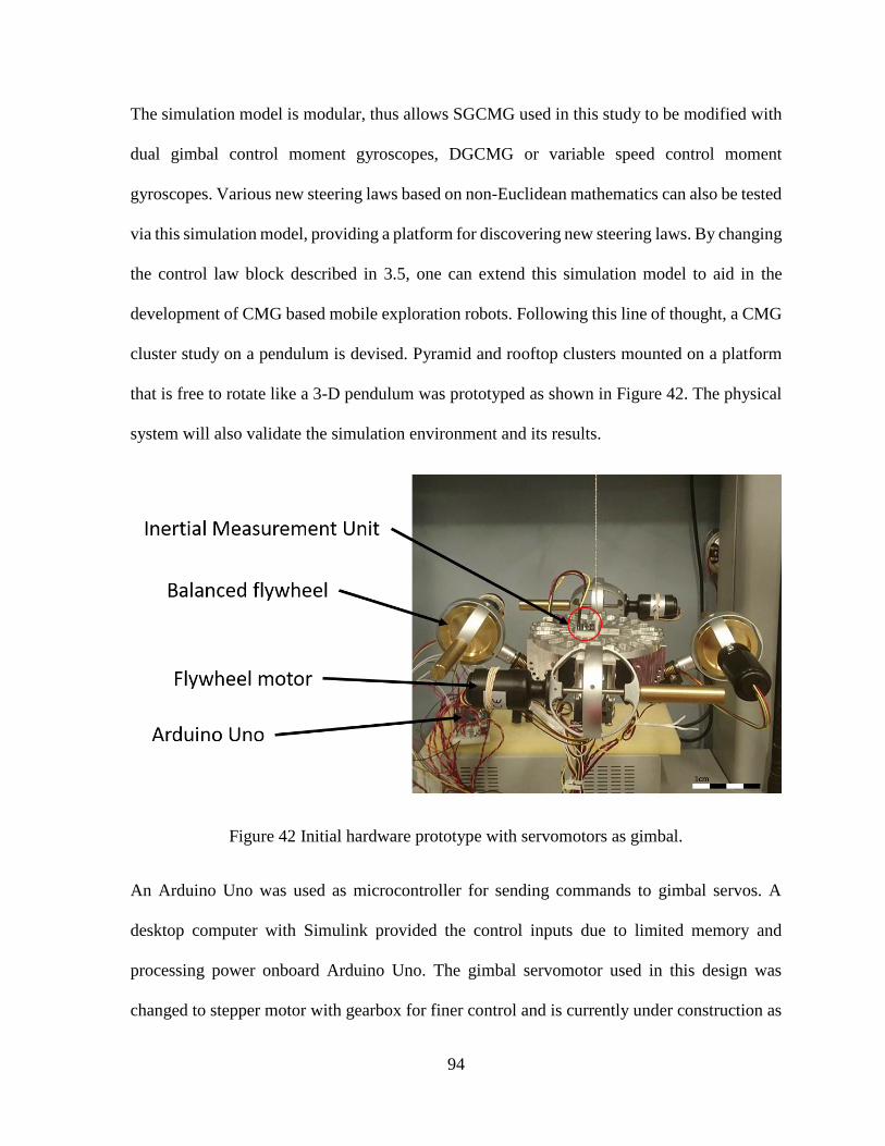
94
The simulation model is modular, thus allows SGCMG used in this study to be modified with
dual gimbal control moment gyroscopes, DGCMG or variable speed control moment
gyroscopes. Various new steering laws based on non-Euclidean mathematics can also be tested
via this simulation model, providing a platform for discovering new steering laws. By changing
the control law block described in 3.5, one can extend this simulation model to aid in the
development of CMG based mobile exploration robots. Following this line of thought, a CMG
cluster study on a pendulum is devised. Pyramid and rooftop clusters mounted on a platform
that is free to rotate like a 3-D pendulum was prototyped as shown in Figure 42. The physical
system will also validate the simulation environment and its results.
Figure 42 Initial hardware prototype with servomotors as gimbal.
An Arduino Uno was used as microcontroller for sending commands to gimbal servos. A
desktop computer with Simulink provided the control inputs due to limited memory and
processing power onboard Arduino Uno. The gimbal servomotor used in this design was
changed to stepper motor with gearbox for finer control and is currently under construction as
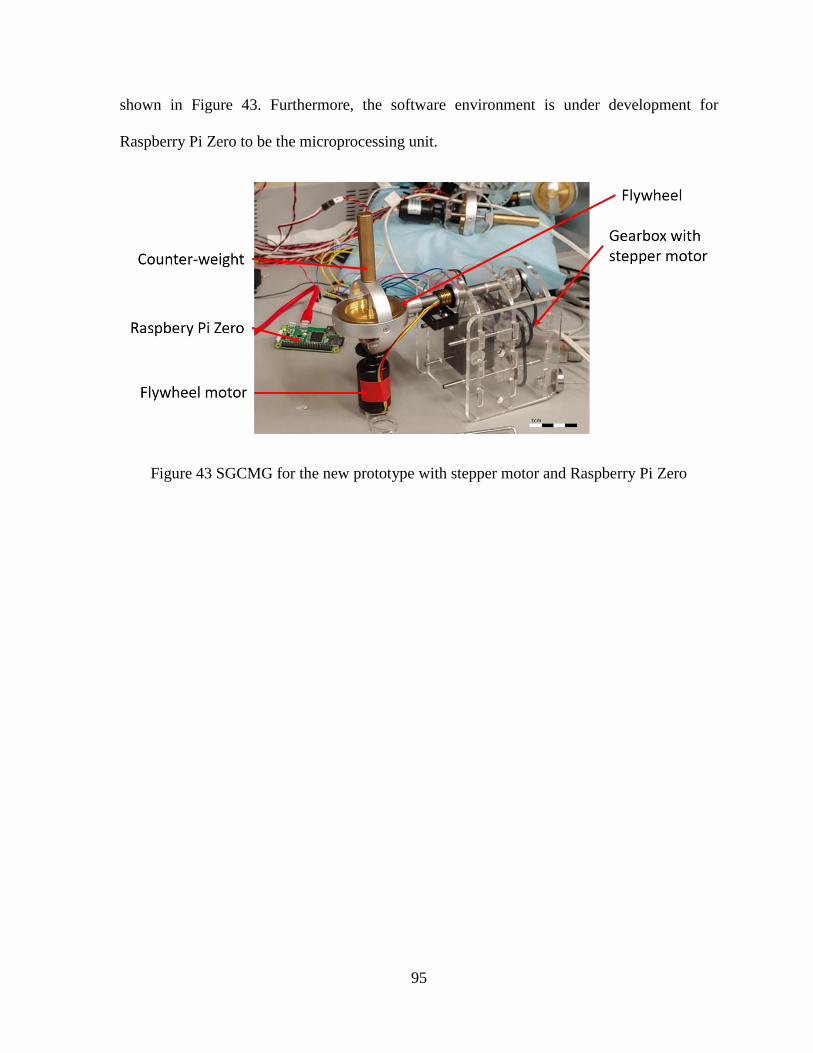
95
shown in Figure 43. Furthermore, the software environment is under development for
Raspberry Pi Zero to be the microprocessing unit.
Figure 43 SGCMG for the new prototype with stepper motor and Raspberry Pi Zero

96
6 References
[1] D. Sandwell, “Brief Overview of Remote Sensing,” LiDAR Remote Sensing and
Applications, pp. 1–17, 2018.
[2] R. R. Auelmann, “Corona KH-4B Satellites,” Space Times, vol. 8, no. 7, p. 11, 1999.
[3] US Geological Survey, “Landsat—Earth Observation Satellites,” no. 8. Earth Resources
Observation and Science (EROS) Center, Sioux Falls, p. 4, 2015.
[4] D. P. Roy et al., “Landsat-8: Science and product vision for terrestrial global change
research,” Remote Sensing of Environment, vol. 145, no. 3, pp. 154–172, 2014.
[5] H. S. P. Wong, “CMOS image sensors - recent advances and device scaling
considerations,” Technical Digest - International Electron Devices Meeting, IEDM, vol.
7, no. 10, pp. 201–204, 1997.
[6] M. Schanz, C. Nitta, A. Bußmann, B. J. Hosticka, S. Member, and R. K. Wertheimer,
“A High-Dynamic-Range CMOS Image Sensor for Automotive Applications,” vol. 35,
no. 7, pp. 932–938, 2000.
[7] M. Bigas, E. Cabruja, J. Forest, and J. Salvi, “Review of CMOS image sensors,”
Microelectronics Journal, vol. 37, no. 5, pp. 433–451, 2006.
[8] C. H. Aw and B. A. Wooley, “A 128 * 128 Pixel Standard CMOS Image sensor with
electronic shutter,” vol. 31, no. 12, pp. 1922–1930, 1996.
[9] E. Asphaug et al., “A cubesat centrifuge for long duration milligravity research,” Nature
Partner Journal Microgravity, vol. 3, 2017.

97
[10] F. A. Leve, B. J. Hamilton, and M. A. Peck, Spacecraft momentum control systems.
2015. [Book]
[11] Q. Shen, D. Wang, S. Zhu, and E. K. Poh, “Finite-time fault-tolerant attitude
stabilization for spacecraft with actuator saturation,” IEEE Transactions on Aerospace
and Electronic Systems, vol. 51, no. 3, pp. 2390–2405, 2015.
[12] D. V. Mateu, “Three-axes attitude determination and control system based on
magnetorquers for small satellites.”
[13] D. H. Ju, “Attitude Control Subsystem Design of the Stable and Highly Accurate
Pointing,” 2017, no. 10.
[14] R. W. Froelicl, “Reaction Wheel Attitude Control for Space Vehicles,” Space
Technology, vol. 7, no. 10, 1959.
[15] E. Yavuzoğlu, “Steering Laws For Control Moment Gyroscope Systems Used In
Spacecrafts Attitude Control,” The Middle East Technical University, 2003.
[16] H. Kurokawa, “A Geometric Study of Single Gimbal Control Moment Gyros A
Geometric Study of Single Gimbal Control Moment Gyros,” Report of Mechanical
Engineering Laboratory, no. 175, 1998.
[17] R. Votel and D. Sinclair, “Comparison of control moment gyros and reaction wheels for
small Earth-orbiting satellites,” Proceedings of the 26th Annual AIAA/USU Conference
on Small Satellites, pp. 1–7, 2012.
[18] P. Dylan, “Characterization And Modeling Of A Control Moment Gyroscope,” Air
Force Institute of Technology, 2015.
98
[19] M. A. Peck, N. York, S. J. Thomas, and J. B. Mueller, “Control-Moment Gyroscopes
for Joint Actuation : A New Paradigm in Space Robotics,” pp. 1–31, 2007.
[20] D. Brown, “Control Moment Gyros as Space-Robotics Actuators,” pp. 1–14.
[21] E. H. Fikes, “Control Moment Gyro For Skylab,” Nasa technical memorandum, vol.
3190, no. September 1968, p. 28, 1971.
[22] L. Morine, “Control Moment Gyroscope Gimbal Actuator Study,” Wright- Patterson
AFB, Ohio, p. 210, 1966.
[23] R. Abramowitz, “Apollo Telescope Mount (ATM) CMG/ EPEA,” The Bendix
Corporation Guidance Systems Division, p. 187, 1975.
[24] T. R. Coon and J. E. Irby, “Skylab Attitude Control System,” IBM Journal of Research
and Development, vol. 20, no. 1, pp. 58–66, 2010.
[25] G. C. Marshall, “High Energy Astronomy Observatory Mission C,” Nasa Technical
Memorandum, no. 1, 1972.
[26] S. C. Rybak, S. I. Lieberman, L. L. Hartter, R. L. Gregory, and A. K. Nakashima,
“Achieving Ultrahigh Accuracy With A Body Pointing CMG/RW Control System,”
AIAA Guidance and Control conference, vol. 73, no. 883, p. 12, 1973.
[27] D. J. Richie, P. Tsiotras, and J. L. Fausz, “Simultaneous attitude control and energy
storage using VSCMGs: Theory and simulation,” Proceedings of the American Control
Conference, vol. 5, no. 404, pp. 3973–3979, 2001.
[28] D. J. Richie, “Combines Attitude Control and Energy Storage for Small Satellites using
Variable Speed Control Moment Gyroscopes,” 2019.
99
[29] V. J. Lappas, W. H. Steyn, and C. Underwood, “Design and Testing of a Control
Moment Gyroscope Cluster for Small Satellites,” Journal of Spacecraft and Rockets,
vol. 42, no. 4, pp. 729–739, 2005.
[30] X. Chen, “A Study of Combined Spacecraft Attitude Control System,” University of
Surrey, 2000.
[31] A. Haslehurst and G. Richardson, “Commercial off the Shelf Components in Reaction
Wheels,” pp. 187–196, 2006.
[32] Steyn WH., L. VJ., and Underwood C:I., “Torque amplification of control moment
gyros,” Electronics Letters, vol. 38, no. 8, pp. 837–839, 2002.
[33] S. M. Seltzer, “Large Space Telescope Oscillations Induced by CMG Friction,” Journal
of Spacecraft and Rockets, vol. 12, no. 7, pp. 0448a-0448a, 2008.
[34] Y. Zhang and J. Zhang, “Disturbance characteristics analysis of CMG due to imbalances
and installation errors,” IEEE Transactions on Aerospace and Electronic Systems, vol.
50, no. 2, pp. 1017–1026, 2014.
[35] K. Jezernik, J. Korelič, and R. Horvat, “PMSM sliding mode FPGA-based control for
torque ripple reduction,” IEEE Transactions on Power Electronics, vol. 28, no. 7, pp.
3549–3556, 2013.
[36] S. Pan, J. H. Zhang, and W. Q. Huang, “Robust controller design of SGCMG driven by
hollow USM,” Microsystem Technologies, vol. 22, no. 4, pp. 741–746, 2016.
[37] T. Kamel, D. Abdelkader, B. Said, S. Padmanaban, and A. Iqbal, “Extended Kalman
filter based sliding mode control of parallel-connected two five-phase PMSM drive

100
system,” Electronics (Switzerland), vol. 7, no. 2, 2018.
[38] X. Sun, Z. Shi, L. Chen, and Z. Yang, “Internal model control for a bearingless
permanent magnet synchronous motor based on inverse system method,” IEEE
Transactions on Energy Conversion, vol. 31, no. 4, pp. 1539–1548, 2016.
[39] Steven R. Crews II, “Increasing Slew Performance Of Reaction Wheel Attitude Control
System,” Naval Postgraduate School, 2013.
[40] V. Nagabhushan, “Development of Control Moment Gyroscopes for Attitude Control
of Small Satellites,” University Of Florida, 2009.
[41] B. Shiotani, K. Patankar, and N. Fitz-coy, “Reliability Analysis and Risk Management
of SwampSat Space Systems Group,” The 5th Nano-Satellite Symposium, pp. 1–11,
2013.
[42] M. D. Carpenter, “Dynamics and Control of Gyroscopically Actuated Space-Robotic
Systems,” no. January, 2009.
[43] M. Shuster, “A survey of attitude representations.,” The Journal of the Astronautical
Sciences, vol. 41, no. 4, pp. 439–517.
[44] N. S. Bedrossian, “Classification of singular configurations for redundant
manipulators,” in IEEE International Conference on Robotics and Automation, 1990,
pp. 818–823.
[45] G. Margulies and J. Aubrun, “Geometric theory of single-gimbal control moment gyro
systems.,” vol. 26, no. 2, p. 1978, 1978.
[46] E. Tokar and V. Platonov, “Singular surfaces in unsupported gyrodyne systems.”
101
Cosmic Research, p. 16, 1979.
[47] N. S. Bedrossian, J. Paradise, E. V. Bergmann, and D. Rowell, “Redundant single
gimbal control moment gyroscope singularity analysis,” Journal of Guidance, Control,
and Dynamics, vol. 13, no. 6, pp. 1096–1101, 1990.
[48] C. J. Stevens and S. E. Fiske, “Control Moment Gyroscope US8205514B2,” 12/016348,
2012. [Patent]
[49] C. Gurrisi, R. Seidel, S. Dickerson, S. Didziulis, P. Frantz, and K. Ferguson, “Space
Station Control Moment Gyroscope Lessons Learned,” Aerospace Mechanisms
Symposium, pp. 161–176, 2010.
[50] L-3 S & N, “The Power to move the space world,” vol. 85, no. May. pp. 448–457, 2003.
[51] C. Gurrisi, R. Seidel, S. Dickerson, S. Didziulis, P. Frantz, and K. Ferguson, “Space
Station Control Moment Gyroscope Lessons Learned,” Proceedings of the 40th
Aerospace Mechanisms Symposium, pp. 161–176, 2010.
[52] F. Leve, “Novel Steering and Control Algorithms for Single-gimbal Control Moment
Gyroscopes,” University Of Florida, 2010.
[53] J. J. Bonn and M. A. Peck, “Dynamic Cmg Array And Method,” 10/681,853, 2009.
[Patent]
[54] “M50 Control Moment Gyroscope (CMG) Specification.” Phoenix, Arizona, p. 2, 2002.
[55] A. Defendini et al., “Control Moment Gyro CMG 15-45 S: A compact CMG product
for agile satellites in the one ton class,” European Space Agency, (Special Publication)
ESA SP, no. 524, pp. 27–31, 2003.

102
[56] Q. Hunstad, “Airbus Defence and Space NEWTON products enable agile satellite
missions,” Defense & Space, no. April, pp. 79–80, 2015.
[57] A. R. Mkrtychyan, N. I. Bashkeev, D. O. Yakimovskii, D. I. Akashev, and O. B.
Yakovets, “Control moment gyroscopes for spacecraft attitude control systems: Current
status and prospects,” Gyroscopy and Navigation, vol. 6, no. 3. pp. 236–240, 2015.
[58] L. M. Gomes, “Bilsat-1 : a low-cost, agile, earth observation m icrosatellite for turkey,”
vol. 5765, no. 03, 2003.
[59] E. Mumm, K. Davis, M. Mahin, D. Neal, and R. Hayes, “Miniature Control Moment
Gyroscope development,” in IEEE Aerospace Conference Proceedings, 2014.
[60] V. Lappas, Dr.W.H.Steyn, and Dr.C.I.Underwood, “Attitude Control for Small
Satellites using Control Moment Gyros,” Acta Astronautica, vol. 51, no. 1–9, pp. 101–
111, 2002.
[61] J. Tallineau and J. Demonty, “Veoware Product Description,” Veoware CMG, 2019.
[Online]. Available: https://www.veoware.space/. [Accessed: 27-Aug-2019].
[62] S. Staff, “DigitalGlobe loses WorldView-4 satellite to gyro failure,” SpaceNews, 2019.
[Online].
[63] V. J. Lappas, “CMG based ACS for Agile small Satellites,” University of Surrey, 2002.
[64] V. Abbasi et al., “NEOSSat Recovery Following Magnetometer and Torque Rod
Failure,” no. June, pp. 1–17, 2018.
[65] W. Larson and R. J. Wertz, Space Mission Analysis and Design, Third edit. 1999.[Book]
[66] S. Clark, “Canadian asteroid-hunting satellite to launch Monday,” Spaceflight Now,

103
2013. [Online].
[67] C. R. Mclnnes, “Large Angle Slew Maneuvers with Autonomous Sun Vector
Avoidance,” vol. 17, no. 4, pp. 875–877, 1993.
[68] A. Tatsch and N. Fitz-Coy, “Dynamic artificial potential function guidance for
autonomous on-orbit servicing,” European Space Agency, (Special Publication) ESA
SP, no. 606, pp. 421–426, 2006.
[69] S. S. Ge and Y. J. Cui, “Dynamic Motion Planning for Mobile Robots Using Potential
Field Method,” Electrical Engineering, vol. 13, no. Med, pp. 207–222, 2002.
[70] W. B. Chzlbb, S. M. Seltzer, and G. C. Marshall, “Skylab Attitude and Pointing Control
System,” NASA Technical Note, no. 6068, p. 16, 1971.
[71] A. Siahpush and J. Gleave, “A brief survey of attitude control systems for small satellites
using momentum concepts,” Proceedings of the 2nd AIAA/USU Conference on Small
Satellites, pp. 18–21, 1988.
[72] T. A. Dahl and P. B. C. Gunter, “An Evaluation of Spacecraft Pointing Requirements
for Optically Linked Satellite Systems,” Georgia Institute of Technology, 2017.
[73] M. Pittelkau, “Pointing error definitions, metrics, and algorithms,” Advances in the
Astronautical Sciences, p. 2003, 2003.
[74] M. E. Pittelkau and W. G. McKinley, “Pointing error metrics: Displacement, smear,
jitter, and smitter with application to image motion MTF,” AIAA/AAS Astrodynamics
Specialist Conference 2012, no. August, pp. 1–19, 2012.
[75] J. P. Mason et al., “MinXSS-1 CubeSat On-Orbit Pointing and Power Performance: The

104
First Flight of the Blue Canyon Technologies XACT 3-axis Attitude Determination and
Control System,” 2017.
[76] Q. Ran, Y. Chi, Z. Wang, P. Image, J. Removal, and J. Property, “Property and Removal
of Jitter in Beijing-1 Small Satellite,” The International Archives of the
Photogrammetry, Remote Sensing and Spatial Information Sciences. Vol. XXXVII. Part
B1. Beijing 200.
[77] Preston M. Burch, “Joint Polar Satellite System (JPSS) Satellite Missions,” European
Space Agency, (Special Publication) ESA SP, 2000. [Online].
[78] M. Mecham, “EO-1 Satellite Missions,” European Space Agency, (Special Publication)
ESA SP, 2000. [Online].
[79] J. Foust, “SpaceX’s Space Internet Woes,” IEEE Spectr., vol. 56, pp. 50–51, 2019.
[80] B. Wallace et al., “The Near Earth Object Surveillance Satellite (NEOSSat),” Photonic
d North, vol. 5578, no. December 2004, p. 7, 2004.