Embed Size (px)
Citation preview

IEEE TRANSACTIONS ON MAGNETICS, VOL. 50, NO. 8, AUGUST 2014 8101710
A Computationally Efficient Method to Determine Iron andMagnet Losses in VSI-PWM Fed Axial Flux Permanent
Magnet Synchronous MachinesPeter Sergeant1,2, Hendrik Vansompel1, Ahmed Hemeida1,2, Alex Van den Bossche1, and Luc Dupré1
1Department of Electrical Energy, Systems and Automation, Electrical Energy Laboratory,Ghent University, Gent 9000, Belgium
2Department of Industrial Technology and Construction, Electrical Energy Research Group,Ghent University, Gent 9000, Belgium
For electrical machines with a 3-D geometry, such as axial flux permanent magnet machines, the computation of iron and magnetlosses in the case of pulsewidth modulation (PWM) supply could be performed by a transient 3-D finite element model (FEM)coupled with an electrical circuit. To reduce the CPU time, in this paper, these losses are computed with acceptable accuracy withoutusing a 3-D transient FEM. The multislice technique is used with a 2-D static FEM, combined with a state space model of themachine. A Preisach hysteresis model is considered to evaluate the iron loss during minor loops. The loss in the electrical steel andin the magnets is evaluated for several PWM frequencies as well as for different segmentations of the magnets.
Index Terms— Axial flux, finite element analysis, losses, permanent magnet synchronous machine (PMSM), Preisach model,pulsewidth modulation (PWM).
I. INTRODUCTION
MOST permanent magnet synchronous machines(PMSMs) are fed by a current-controlled voltage
source inverter (VSI). In general, the variable voltage sourceis obtained by pulsewidth modulation (PWM). By combiningthe PMSM with a VSI-PWM inverter, a highly dynamiccontrolled electric drive at variable speed is obtained. Theharmonic components present in the output voltage of theinverter affect the performance of the machine. Althoughthe high harmonic components in the phase voltages will befiltered by the inductances in the machine, a nonnegligibleripple in the phase current will still be present. These currentripples will increase the losses in the machine. The currentripple will have a direct influence on the core losses [1]–[3]and the induced eddy currents in the permanent magnets(PMs) [4]. In [5], it is shown that iron loss increases by alimited amount by adding PWM, but the eddy-current loss inPMs increases a lot. Segmentation of magnets is very usefulif the carrier frequency is rather low and seems to have loweffect in case the carrier frequency is high. In [6], the sameconclusions are found for a PMSM with buried magnets; thecited paper shows a small increase of iron loss ( 20%), but adifference in PM loss up to 500%.
The classical way to study eddy currents in magnets andcore loss due to PWM is a transient finite element model(FEM) simulation coupled to an electric network. In the caseof a 3-D FEM, this may result in very long CPU times, e.g.,
Manuscript received November 25, 2013; revised January 29, 2014;accepted February 25, 2014. Date of publication February 27, 2014; date ofcurrent version August 15, 2014. Corresponding author: P. Sergeant (e-mail:[email protected]).
Color versions of one or more of the figures in this paper are availableonline at http://ieeexplore.ieee.org.
Digital Object Identifier 10.1109/TMAG.2014.2308904
148 h in [5] on a Core2 Duo (3.16 GHz) PC. In [6], the effectof PWM is computed on iron core and PM loss in a PMSMwith buried magnets. The hysteresis and classical loss are esti-mated based on a material specific constant and rescaled withthe square of the peak induction and with the frequency (hys-teresis loss) or frequency squared (classical loss). The methodcouples an FEM of the machine to a converter, which resultsin a very computationally demanding time domain simulation.
Another way of determining the PWM loss is given in [7].The rotor is locked and the machine is supplied with PWMwaveforms. The fundamental frequency of the PWM inverter isset to be zero. As the mechanical output power and mechanicalloss are zero, the magnet and core loss caused by PWM canbe found by subtracting the copper loss from the measuredelectric input power. A similar approach to simulation isfollowed in [8] by supplying the machine at standstill with theharmonic components of a PWM signal in a time harmonicFEM. To separate the iron core loss from the magnet loss, theexperiment in [7] is repeated for the rotor without magnets.
When having the flux density waveforms in the stator iron(e.g., from FEM), the PWM losses in the stator iron laminationcan be computed by one of the three methods of [9]. All threemethods are based on the loss separation technique in [10].The first one introduces a form factor to account for the pulsedvoltage waveform. The second one computes the classicallosses with the low-frequency approximation (no skin effectin the lamination), and the third one uses the high-frequencyapproximation (skin effect in the lamination). In [11], the sameauthors of [9] propose the following simple technique. For avoltage waveform including (PWM) harmonics, the methodcomputes the hysteresis part of the iron loss based on theaverage rectified value of the waveform, and the eddy-currentpart based on the rms values of the waveform. Minor hysteresisloops are neglected.
0018-9464 © 2014 IEEE. Personal use is permitted, but republication/redistribution requires IEEE permission.See http://www.ieee.org/publications_standards/publications/rights/index.html for more information.
8101710 IEEE TRANSACTIONS ON MAGNETICS, VOL. 50, NO. 8, AUGUST 2014
Many more papers can be found about computing PWMlosses. Knight et al. [12] present the integration of a simplefirst-order 1-D approximation of the eddy current distributionwithin the lamination into a 2-D FEM. In [13], an analyticalapproach is developed to compute the increase in core loss inthe case of broken rotor bars in asynchronous machines thatare controlled by an inverter with PWM.
None of the above methods includes hysteresis models thatconsider minor loops. However, other papers do include hys-teresis as well. In [14], an FEM that is coupled to a hysteresismodel also computes the iron loss. In this hybrid iron lossmodel of [14], the magnetic field strength components arecalculated based on a static Preisach model and a simplifieddynamic model. The constitutive nonlinear relation in the 2-DFEM is numerically handled by the fixed-point technique.A simplified hysteresis model is introduced in [15] to computePWM loss. In [16], a Preisach model is coupled to a 2-D FEMthat uses the differential permeability, but this paper does notstudy a PWM application. It is also possible to study PWM in afrequency domain FEM, considering ferromagnetic hysteresisand eddy currents [17] and using a classical Preisach model ashysteresis model. Even more accurate but more time consum-ing is the approach of Bottauscio and Chiampi [18] to couplethe 2-D FEM with a 1-D electromagnetic diffusion equationin the lamination depth. The 1-D diffusion equation can alsobe solved a posteriori, such as in [19], to study the loss ofhigh-frequency pulses for sensorless control.
In this paper, we propose a less computationally demandingapproach that nevertheless gives a good estimation of the rotorloss and iron loss caused by PWM in an axial flux PMSM witha 3-D geometry. As the ripple in the current waveform causesinternal loops in the magnetic field, a Preisach model for thecorrect evaluation of the hysteresis (loss) is considered. Themethod is applied to the type of axial flux machines studiedin [20] and [21].
II. METHODOLOGY TO COMPUTE IRON LOSS
AND MAGNET LOSS
Because of the inherent 3-D geometry of the axial flux PMmachine, the conventional approach with a transient 2-D FEMcoupled to an electrical circuit is not accurate at all. Replacingthe 2-D FEM by a 3-D FEM in this approach would causelarge CPU times.
In this paper, we compute the iron loss and magnet losscaused by PWM without a transient 3-D FEM. The pro-posed methodology consists of several steps, but none ofthem requires either a 3-D FEM, which may suffer fromnumerical noise, or a transient FEM, which may suffer fromconvergence problems. Nevertheless, the methodology canpredict the PWM loss for an axial flux PMSM with a 3-Dgeometry.
1) A multislice 2-D static FEM approach for several rotorpositions makes it possible to reconstruct the 3-D fieldwith a good accuracy (Section III-A). The conventionalFEM with vector potential formulation requires theelectric phase current as the input. The current wave-forms are determined based on field-oriented control of
the machine without PWM (Section III-B). The voltagewaveforms are then determined in postprocessing.No induced currents are considered in this step.
2) The PWM voltage signal is generated for a given DCbus voltage by a PWM-generating algorithm, taking thevoltage waveforms from the multislice-2-D models asthe reference signal (Section IV).
3) A state space model of the machine computes thecurrent waveforms with the PWM voltage signal as theinput (Section V).
4) The current waveforms with PWM are used as an inputfor the multislice 2-D model. Note that a transient2-D simulation of the multislice model would not giveacceptable results, as it assumes infinite radial magnetlength, while the magnets are very short in radialdirection in each layer.
5) An iron loss model computes the iron core lossa posteriori (Section VI).
6) The magnet loss is computed via a 2-D–2-D coupledapproach (Section VII).
III. MULTISLICE 2-D APPROACH FOR AN AXIAL FLUX
MACHINE WITH FIELD-ORIENTED CONTROL
A. Multislice Model
In this paper, the static multislice-2-D modeling is thestarting point for all simulations. In this technique, a 2-D fieldcomputation is performed in several cylinder-shaped planes orslices, each at an a priori chosen radius. Each slice modeldescribes an axial flux machine with short radial thicknessas a linear machine, i.e., a machine without curvature. Thetotal machine performance is obtained by the summation ofall linear machines [22]. This approach was used in [20] toreconstruct the 3-D field pattern of the axial flux machineand to use this reconstructed field to compute a posteriori theinduced currents in the magnets. This quasi-3-D approximationuses six computation planes, because in the cited paper,it was proven by experiments that six planes are enoughto have sufficient accuracy. The planes are at equal radialdistances from each other, equally distributed over the radialheight of the active part of the machine. The global solutionof the entire machine is computed by a weighted sum ofthe contributions of all computation planes. In addition, thecomputation of electromotive force (EMF) and torque is donefor each computation plane separately, and then the weightedsum is taken. The models use a single-valued nonlinearBH-characteristic. Although the method neglects fringingfluxes in the radial direction, the induced magnetic currentdensity distribution was much more accurate and less noisythan the distribution obtained with a transient 3-D model thatsuffered from memory problems and a high CPU time. Themodel is validated for the considered axial flux PMSM in [23]:the waveforms of EMF and torque at both no load and ratedload correspond well to measurements.
This multislice model can be seen as a system with aspecified set of inputs and outputs. The inputs are as follows:
1) the phase currents in the windings;2) the angular position of the rotor.

SERGEANT et al.: COMPUTATIONALLY EFFICIENT METHOD TO DETERMINE IRON AND MAGNET LOSSES 8101710
TABLE I
PROPERTIES OF THE AXIAL FLUX PMSM
The outputs are as follows:1) the flux linkages with the windings;2) the magnetic flux density pattern in the stator core
elements;3) the axial component of the magnetic flux density at the
surface of the PMs and rotor.In preprocessing, the relation between the phase currents
and the angular position of the rotor is specified. In thispaper, a field-oriented control of the machine is assumed: thesinusoidal phase currents are imposed in quadrature to the axisof the PMs. This results in a phase current in phase with thefundamental component of the back EMF.
In postprocessing:1) the flux linkages are used to calculate the phase voltages;2) the magnetic flux density pattern in the stator core
elements is used to calculate the stator core loss;3) the axial component of the magnetic flux density at the
surface of the PMs and rotor is used to calculate theeddy-current loss in the PMs and rotor.
The static multislice-2-D modeling is hence only able tosimulate the voltage output, giving a specified current input.These voltage waveforms will be used as reference waveformsto make the PWM in step 2.
B. PMSM With Field-Oriented Control
The considered machine is a 16-pole axial flux PM machinewith 15 tooth coil windings. The properties are given inTable I.
Field-oriented control of the axial flux PM machine requiresthe current to be controlled independently. In particular, thefundamental component (ν̃ = 1) of the magnetic flux densityvector of the PMs should be perpendicular to the flux den-sity vector produced by the stator currents. This yields themaximal producible electromagnetic torque per unit current.The VSI-PWM uses PWM and has a current controller witha sufficiently high bandwidth. The control scheme for such afield-oriented control of a PMSM is shown in Fig. 1.
In this paper, we choose a pure sinusoidal current I 1̃in phase with the fundamental component of the backEMF E 1̃. This choice results in the maximal correspondingpower output. In this case, the power factor is not equal toone and the converter will have to deliver reactive power
Fig. 1. Control scheme of a field-oriented control of a PMSM using aVSI-PWM.
to compensate the inductive behavior of the PMSM. On themachine side, the fundamental components of the current andthe EMF being in phase results in the best achievable energyefficiency, as the output torque is maximized for the samecopper loss. Considering the losses in both the machine and theconverter, the optimum of energy efficiency might be obtainedfor a different power factor.
IV. PULSEWIDTH MODULATION
The aim of this paper is to investigate the losses due toPWM. Therefore, the voltage waveform obtained in step 1(Section III-A) that results in a pure sinusoidal current inphase with the fundamental component of the back EMF ischosen as the reference waveform. Notice that this voltagewaveform is not sinusoidal in spite of the sinusoidal currents.In this section, step 2 is explained, i.e., how the PWM voltagewaveform is calculated.
The modulation technique is shown in Fig. 2. The simplestway to generate a PWM signal is the intersective method.This method only requires a carrier (modulation waveform)and a comparator. Commercial PWM drives mostly use othertechniques, such as sampled PWM, space vector modulation,or computed commutation angles, to minimize a number ofcurrent harmonics. Sometimes third harmonic components areinjected. The type of PWM used does not generate signifi-cantly different harmonic rms voltages as far as the polarityconsistency rule is maintained. As the rms voltage is relatedto the eddy-current loss in the iron [11], this means that, aslong as no overmodulation is done, the different versions ofPWM sampling algorithms will not have much influence onthe results in this paper.
The arbitrary carrier waveform is chosen to be a tri-angular waveform, with a frequency fc and an amplitude
8101710 IEEE TRANSACTIONS ON MAGNETICS, VOL. 50, NO. 8, AUGUST 2014
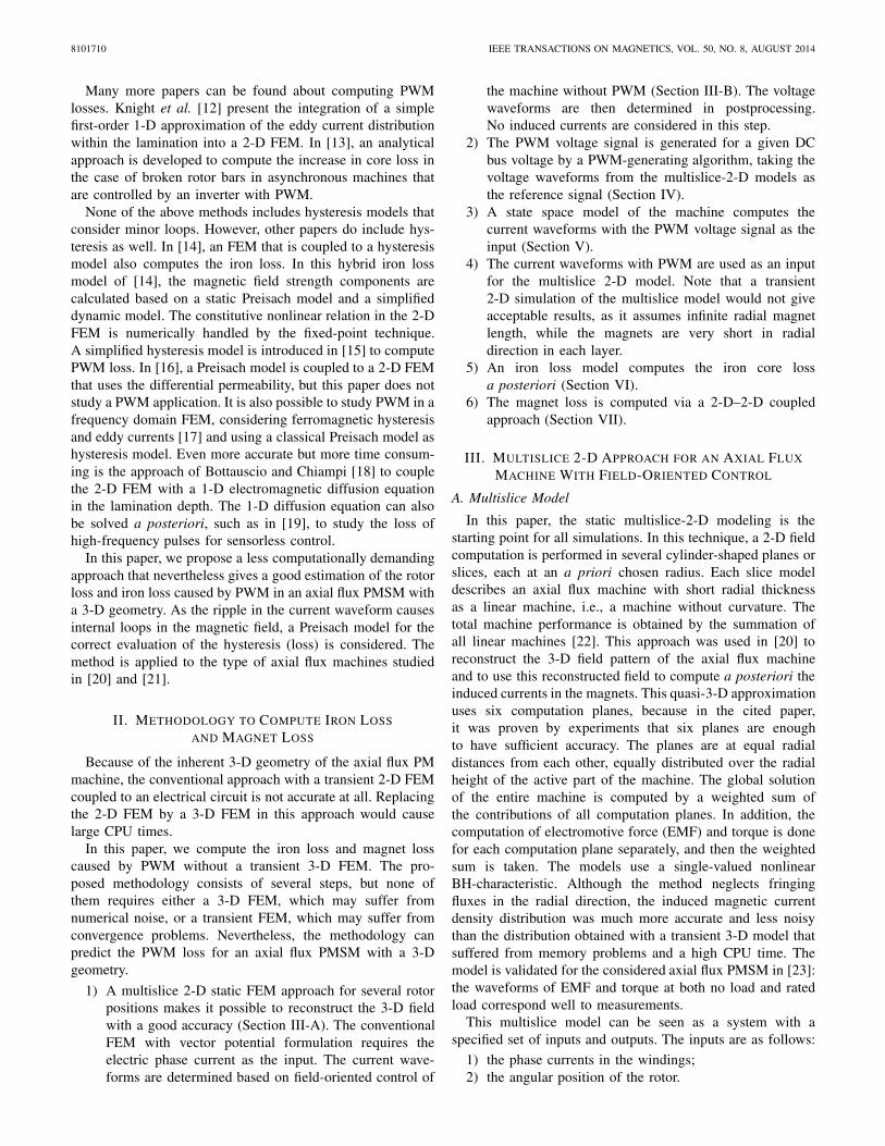
Fig. 2. Upper: voltage reference waveform and carrier (modulation wave-form). Lower: voltage reference waveform and generated PWM signal by theintersective method using a comparator. One fundamental (electrical) periodof the voltage reference waveform is illustrated.
Fig. 3. Amplitudes of the PWM voltage for fc/ f = 30.
slightly higher than the peak value of the reference waveform.The frequency of the carrier has to be chosen sufficientlyhigh in order not to affect the load. As will be illustratedin a successive section of this paper, the switching frequencyhas a major impact on the ripple in the phase current andconsequently on the losses in the machine. In Fig. 2, thefrequencies of the carrier waveform and reference waveformare 10 kHz and 333 Hz, respectively. The Fourier spectrum ofthe PWM waveform shown in Fig. 3 clearly contains higherharmonic components.
As could be expected intuitively, the harmonic componentsnear the frequency of the carrier waveform and its multiplesstrongly dominate the high harmonic content. The Fourierspectrum includes the possible harmonic numbers
ν̃ = kfc
f± l (1)
corresponding with the frequencies
fs = k fc ± l f (2)
with fc the carrier frequency, f the fundamental frequency,k ≥ 0, l ≥ 0, and k + l odd.
Indeed, in the Fourier spectrum of the PWM waveformshown in Fig. 3, next to the fundamental component of thereference voltage waveform ν̃ = 1, the harmonic components
near the frequency of the carrier waveform ν̃ = fc/ f = 30and its multiples have high amplitudes: 30±2 ( fc±2 f ), 60±1(2 fc ± 1 f ), 60 ± 3 (2 fc ± 3 f ), . . . .
Although the PM machine is fed with PWM voltage wave-forms that include a high harmonic content, the low pass filteraction of the inductances of the machine limits the ripple inthe current waveform. The simulation of the current waveformin the VSI-PWM fed machine (step 3) is discussed in thefollowing.
The losses in the VSI-PWM are not investigated.
V. STATE-SPACE MACHINE MODEL
To calculate the current waveform for a given voltagewaveform, a state space model of the axial flux machine withlinear coefficients is presented and used to simulate the currentwaveform. Nevertheless, in the Appendix the nonlinear variantis discussed.
For a PM machine, the basic equation that expresses therelation between voltage V, back EMF E, and phase current Iis given by
V = E + RI + d
dt(LI) . (3)
The voltage V, back EMF E, and phase current I are columnvectors represented in the abc-system
V =⎡⎣
Va
Vb
Vc
⎤⎦, E =
⎡⎣
Ea
Eb
Ec
⎤⎦, I =
⎡⎣
Ia
Ib
Ic
⎤⎦. (4)
The resistance matrix R is given by
R =⎡⎣
Rs
Rs
Rs
⎤⎦ (5)
and the inductance matrix by
L =⎡⎣
Ls Ms Ms
Ms Ls Ms
Ms Ms Ls
⎤⎦. (6)
As the surface PMs have a relative permeability very closeto unity and saturation of the magnetic circuit is neglectedin the linear model, the inductance matrix is not dependingon the angular rotor position. In a balanced three-phasesystem, the diagonal elements represent the inductance coeffi-cients of the tooth coils Ls , and the other elements representthe mutual inductance coefficients Ms . The inductance matrixis hence symmetric.
The inductance matrix considering the nonlinear behaviorof the stator core material is presented in the Appendix.Although the nonlinear model describes the PM machine moreaccurately, the usage of the linear model is maintained in thissection. This is acceptable for the considered machine, becausethe material is not much saturated, as will be illustrated inSection VI.
The EMF is calculated by taking the time derivative of thePM flux linkage ψPM, i.e., the flux linkage caused by the PMsonly, so without armature reaction
E = dψPM(θ)
dt= dψPM(θ)
dθ
dθ
dt= dψPM(θ)
dθω (7)

SERGEANT et al.: COMPUTATIONALLY EFFICIENT METHOD TO DETERMINE IRON AND MAGNET LOSSES 8101710
where
ψPM(θ) =
⎡⎢⎢⎣ψPM
a (θ)
ψPMb (θ)
ψPMc (θ)
⎤⎥⎥⎦. (8)
The values of dψPM(θ)/dθ are calculated using the staticFEM and are stored in a lookup table. Hence, the back EMFE considers the presence of additional harmonic components.
The tooth coil’s inductance coefficient and mutual induc-tance coefficient are calculated by making use of the definitionof the chord inductance
Ls = ψi (Ii )− ψPMi
Ii, i = a, b, c (9)
Ms = ψi (I j )− ψPMi
I j, i = a, b, c, j = a, b, c, j �= i. (10)
In the calculation of the elements of the inductance matrix inthe case of nonlinear material behavior, the tangent inductioncoefficient definition is used.
With respect to the calculation of the inductance coefficientsby making use of the multislice-2-D modeling technique, itshould be noticed that the inductance coefficients are under-estimated. The multislice-2-D modeling technique considersonly paths of the magnetic flux in the computation plane.The flux paths in the end windings at the inner and outerdiameter are not considered. Hence, the accurate prediction ofthe inductance coefficients requires full 3-D modeling of theaxial flux PM machine.
The basic equation for the PM machine (3) is subsequentlytransformed into a state space model
dIdt
= −L−1RI + L−1 (V − E) . (11)
In this state space model, the output and state are the phasecurrent vector I, while the model has (V − E) as an input. Asthe EMF is based on FEM (via a lookup table) and also theinductance is based on FEM via (9), (11) considers nonlineareffects and distortion of field waveforms. Nevertheless, (11)remains an approximation because of the choice to makethe inductance a constant although it may depend on theinstantaneous currents in the machine.
The state space model with linear coefficients presented inthis section has the advantage of very short evaluation times.The simulation time is mainly determined by the search andinterpolation operation in the lookup table for the flux linkageof the PM flux.
A. Calculation Steps
The calculation of the current waveform in the case of aVSI-PWM fed machine includes three steps.
1) Simulation of the output voltage for a given currentinput without PWM (field-oriented control) using staticmultislice-2-D modeling (step 1).
2) Generation of the PWM-signal. Here, the output voltageof the static multislice-2-D modeling is used as thereference signal for PWM (step 2).
Fig. 4. Phase current waveforms for the VSI-PWM fed machine correspond-ing to a carrier frequency of 10 kHz.
Fig. 5. Phase current waveforms for the VSI-PWM fed machine correspond-ing to a carrier frequency of 5 kHz.
3) Using this PWM-signal, the state space model computesthe corresponding current waveform (step 3).
When the main goal is to study losses, step 2 is preferredrather than implementing a full VSI-PWM including the tuningof the parameters of the current controller.
B. Current Waveforms for Carrier Frequencies
The simulations for the current waveform are performed atrated load and speed; the waveform for the current is set to7 A, having only a fundamental frequency of 333 Hz (field-oriented control). A PWM carrier frequency of 10 kHz isapplied (Fig. 4).
The value for the phase resistance Rs is estimated to be0.2 �, and the values for the inductance and mutual inductancecoefficients calculated by (9) and (10) are 7.4 mH and 323 μH,respectively.
Given the PWM signal as an input, the state space model(11) calculates the corresponding current waveform. For the10-kHz frequency of the carrier, the phase current (in phase a)is shown in Fig. 4. The ripple in the current due to the PWMsignal (voltage) is clearly observed.
As the current ripple is a function of the carrier frequency,the current waveforms for a 5 and 20 kHz carrier frequencyare shown in Figs. 5 and 6, respectively. An increasing carrier
8101710 IEEE TRANSACTIONS ON MAGNETICS, VOL. 50, NO. 8, AUGUST 2014
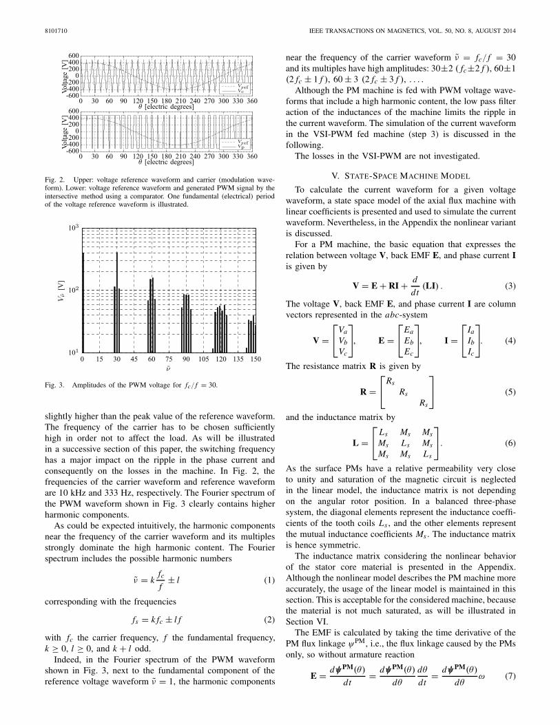
Fig. 6. Phase current waveforms for the VSI-PWM fed machine correspond-ing to a carrier frequency of 20 kHz.
frequency has an indisputable impact on the mitigation of thecurrent ripple.
Focusing only on the machine, the carrier frequency shouldbe taken as high as possible. A high frequency of the carrierresults in high switching losses in the IGBT s of the VSI. Theminimization of the losses in the combined system, machineand power electronics, will not be examined in this paper.
VI. CORE LOSSES
To calculate the corresponding stator core losses, in step 4(Section II), the current waveforms obtained through the statespace model are used in the multislice 2-D finite elementsimulations. The waveforms B(t) are reconstructed in the 3-Dvolume of the stator core. Based on these waveforms, in step 5,an evaluation of the core losses is performed based on theloss separation technique. The calculations are performed fora M600-50A material.
A. Minor Hysteresis Loops
Bertotti’s loss separation method subdivides the stator corelosses into a hysteresis loss component, a classical loss com-ponent, and an excess loss component
Wfe(B, t) = Why + Wcl + Wexc (12)
= kh Bαp + σd2
12
∫ T
0
∣∣∣∣d B(t)
dt
∣∣∣∣2
dt
+√σGV0S
∫ T
0
∣∣∣∣d B(t)
dt
∣∣∣∣1.5
dt (13)
with kh and α being fitting parameters, Bp the peak induction,σ the material conductivity, d the thickness of the lamination,d B/dt the time derivative of the magnetic flux density, G adimensionless coefficient, S the surface of the lamination, andV0 a parameter characterizing the statistical distribution of thelocal field of the magnetic objects introduced in [10]. Here,kh and α are fitted based on quasi-static measurements onan Epstein frame. The excess loss coefficient is fitted basedon measured hysteresis loops with sinusoidal flux densitywaveforms with amplitudes up to 1.8 T and frequenciesbetween 10 and 700 Hz, causing a good correspondence ofpredicted and measured losses up to frequencies above therated operating frequency of the motor (333 Hz).
Fig. 7. Waveform for the magnetic flux density in the center part of thecore. Values correspond to the inner diameter laminations.
The calculation of the classical loss component and excessloss component could be performed on any waveform ofthe magnetic flux density. However, for the hysteresis losscomponent, (13) assumes that no local minima or maxima arepresent in the waveform of the magnetic flux density. In theVSI-PWM fed machine, local minima or maxima are observedin the waveform of the magnetic flux density. In Fig. 7, thewaveform of the magnetic flux density in the center part ofthe stator core is shown.
The calculation of the hysteresis loss component based onthe peak value of the magnetic flux density, as presented in(13) is only a first approximation, as it does not consider thelocal minima or maxima in the waveform of the magneticflux density. To check the error that is made by neglectingthe local minima or maxima in the waveform of the mag-netic flux density, the hysteresis is modeled by the Preisachmodel [24], and the hysteresis loss component is calculateda posteriori. The Preisach model was used to examine theinfluence of minor loops on the hysteresis loss in the statorcore elements. Based on hysteresis loop measurements onthe Epstein frame, a Lorentzian Preisach distribution functionwas fitted for the considered material [26, eq. (3)]. Rotationallosses are not considered. The considered axial flux machinedoes not have a stator yoke, so that rotational fields occuronly in the tooth tips. It was shown in [25] that this region islimited.
As the PMs cause a magnetic flux in the laminations of thestator cores, the average value of the magnetic flux densitiesobtained through the static finite element computations fordifferent rotor positions is taken as an input for the hysteresismodel. To model the variation of the magnetic field andmagnetic flux density over the cross section of the lamination,a 1-D diffusion equation is used.
The output of the Preisach model at the center and the edgeof a lamination is shown in Fig. 8. Obviously, the presenceof minor loops is less visible at the center compared with thepresence at the edges because of skin effect. The minor loopsresulting from the PWM have a high frequency and are hencedisplaced to the edges of the laminations.
Here, it is illustrated that the local minima and maxima inthe waveform of the magnetic flux density in a PMSM with

SERGEANT et al.: COMPUTATIONALLY EFFICIENT METHOD TO DETERMINE IRON AND MAGNET LOSSES 8101710
Fig. 8. Hysteresis loops obtained through Preisach modeling at the center ofa lamination (left) and the edge of a lamination (right), taken for a laminationat the inner diameter region of the machine.
PWM supply result in minor hysteresis loops. The presence ofthese minor loops introduces supplementary hysteresis lossesin the stator core. For the 10-kHz carrier waveform, the hys-teresis loss was estimated at 109% of the one in the machinewithout PWM. Hence, neglecting the minor hysteresis loopsresults in an underestimation of the hysteresis loss componentwith (only) 9%, which is 5 W. As these 5 W are very limitedcompared with the total core loss of 165 W, the complexityof the Preisach modeling surpasses the improvement of theaccuracy. Therefore, the previously introduced model for thehysteresis loss (13) based on the peak value of the magneticflux density is still an acceptable model in case of PWM forthe considered PMSM.
The minor hysteresis loops have been originally analyzed in[27], where a simple method is presented to estimate the minorloop hysteresis loss in thin laminations. A simpler alternativecould be to use a formula like in [15], which considers lossesin minor loops without using a full hysteresis model. Thecited paper proposes an additional loss term Pi (Bi , Bav,i )that depends on the amplitude of the minor loops and theiroffset (their position in the BH-plane)
Ph = kh f Bαp +m∑
i=1
Pi (Bi , Bav,i ) (14)
where m is the number of minor loops in the period of thefundamental component, Bi the size of the minor loop, andBav,i the average value of the minor loop (offset), whichrepresents the position in the major hysteresis loop. Thisloss function has to be determined from measurements or ahysteresis model, so it is an alternative in case neither BH-loopmeasurements nor hysteresis models are available.
B. Simulation Results
The results of the simulations of the core losses for differentfrequencies of the carrier are shown in Table II. The valuesbetween brackets represent the relative increases with respectto the machine with sinusoidal current waveforms withoutPWM.
The effect of the PWM is most visible in the increase of theclassical losses. The increase of the excess loss component andthe hysteresis component, even if the Preisach model is used,
TABLE II
EFFECT OF CARRIER FREQUENCY ON THE STATOR CORE LOSSES AT
RATED LOAD, SHOWING HYSTERESIS LOSS Phy , CLASSICAL LOSS Pcl ,
EXCESS LOSS Pexc , AND TOTAL IRON LOSS PFe
Fig. 9. Loss distribution in W/m2 in one of the six slices of the stator teethat 5 kHz PWM frequency.
is less pronounced. On the other hand, a positive influence ofa high carrier frequency on the core loss in the machine isobserved. The loss distribution in the stator core is shown inFig. 9.
VII. EDDY-CURRENT LOSS IN THE PMS
Finally, in step 6 (Section II), the eddy-current loss inthe PMs is calculated using the multislice 2-D–2-D compu-tation technique that was introduced in [21]. The 1-D airgap magnetic fields of multiple multilayer 2-D finite-elementsimulations are combined to construct a 2-D air gap magneticfield using static simulations. Then, this 2-D air gap magneticfield is imposed to a time harmonic 2-D FEM of the PMto calculate the eddy currents and eddy-current losses. Forthe considered axial flux PMSM with properties in Table I,a validation of this approach is done in [21] by comparingthe results of the 2-D–2-D approach with a transient 3-DFEM. The skin depth is considered during the calculationof the eddy currents in the PMs in the following way. The2-D–2-D approach computes the induced current distributionJ (r, φ) in a plane on the surface of the magnets at theair gap side. Skin effect causes a mitigation of the eddycurrents in axial direction z. This is considered by multiplyingthe current density with an exponential function e−z/δ thatrepresents the field mitigation because of the skin depth δ.Then, the volume integral of J 2/σ is taken. Although the skineffect is considered a posteriori, the validity of this model islimited as it neglects the reaction field of the currents in themagnets. In other words, it is assumed that the eddy currentsinduced in the PMs do not have an influence on the resul-tant magnetic flux density. This assumption will be violated
8101710 IEEE TRANSACTIONS ON MAGNETICS, VOL. 50, NO. 8, AUGUST 2014
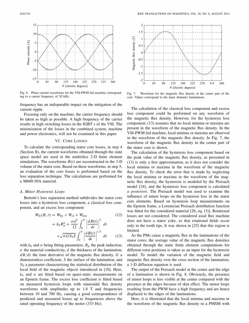
Fig. 10. Considered magnet segmentation grades. (a) Bulky: no segmentation.(b) Two segments. (c) Four segments. (d) Fourteen segments.
for thick magnets and for high frequencies. Therefore, themultislice 2-D–2-D model will be less accurate for VSI-PWMfed machines with thick magnets and high carrier frequency.However, for realistic carrier frequencies and magnet thick-nesses, skin effect in magnets occurs only in a limited numberof PMSMs. For example, with a conductivity of 0.6 MS/mand a permeability of 1.05μ0, the penetration depth at 1 and10 kHz is 20.1 and 6.3 mm, respectively. Small PMSMs canbe made with magnets of only 2-mm thickness [8]; largemachines have thicker magnets but usually also lower PWMfrequencies.
Nevertheless, in case the approach is not valid, transienttime simulations on the full 3-D FEM [28] can be done.This will consider the reaction field of the eddy currents inthe PMs. Although this technique is more correct from thetheoretical point of view, the accuracy of the predicted lossstrongly depends on the very small time step in case of smallperiods of the carrier, and the mesh refinement in the magnetdomains with small penetration depth.
We consider four segmentation possibilities for the T-shapedmagnets in the axial flux machine, as shown in Fig. 10. Noticethat with the coupled 2-D–2-D approach, it is possible tomodel the segmentation in the transversal plane. The first2-D model is the slice model, in a circumferential plane,and cannot include segmentation in the radial direction. Thesecond 2-D model is in a transversal plane, and can includesegmentation. In Table III, the magnet loss is given in caseof supply by the reference voltage waveforms without PWM.The loss distribution in the magnets is given in Fig. 11.
In Table IV, the eddy-current loss in the magnets is summa-rized for supply by PWM for three carrier frequencies and fordifferent segmentation grades. The table confirms the findingsof [5]: for high PWM carrier frequencies, segmentation is
TABLE III
EFFECT OF SEGMENTATION ON THE MAGNET EDDY-CURRENT LOSS IN
CASE OF SUPPLY WITHOUT PWM
Fig. 11. Loss distribution in W/m2 in an unsegmented magnet at 5 kHzPWM frequency, obtained by the coupled 2-D–2-D approach.
TABLE IV
EFFECT OF MAGNET SEGMENTATION AND PWM CARRIER FREQUENCY
ON MAGNET EDDY-CURRENT LOSS AT RATED LOAD
less effective in reducing magnet loss than for low PWMfrequencies.
As for the loss in the stator cores, an increasing carrierfrequency results in a decrease of the eddy-current loss inthe PMs. Therefore, it can be concluded that an increasingcarrier frequency results in lower power losses in the machine.Despite the lower power loss in the machine for highercarrier frequencies, the switching losses in the IGBTs of theVSI-PWM increase with increasing carrier frequencies. There-fore, the power losses in the entire electric part of the drivetrain, i.e., power electronic devices and electrical machine,should be considered when selecting the most appropriatefrequency for the carrier.
On the other hand, the effectiveness of the segmentation ofthe PMs is clearly visible in case of a VSI-PWM fed machine.In Figs. 12 and 13, the eddy-current losses correspondingto each harmonic component are shown for the bulky (nosegmentation) PM and the PM with 14 electrically isolatedsegments.
Whereas segmentation of the PMs results in a decreaseof the eddy-current losses in general, comparison ofFigs. 12 and 13 clearly indicates that the decrease of theharmonic loss components is most significant for the highernumbers, i.e., the higher frequencies due to the PWM. Hence,a high segmentation grade is a very effective measure to reducethe additional losses due to PWM.

SERGEANT et al.: COMPUTATIONALLY EFFICIENT METHOD TO DETERMINE IRON AND MAGNET LOSSES 8101710
Fig. 12. Eddy-current losses in a single PM with no segmentation as afunction of the harmonic order ν during load.
Fig. 13. Eddy-current losses in a single PM consisting of 14 electricallyisolated segments as a function of the harmonic order ν during load.
VIII. CONCLUSION
This paper presents a methodology to compute the iron lossand magnet loss caused by PWM in a computationally efficientway for a VSI-PWM fed axial flux PM machine with 3-Dgeometry.
To model a VSI-PWM fed axial flux PM machine, a statespace model for the machine was introduced. This state spacemodel was used to calculate the phase currents correspondingto the imposed PWM signal as a voltage input. Then, theobtained phase currents were imposed to the multislice 2-Dmodel to calculate the losses in the stator cores and the eddy-current losses in the PMs. The simulations were performed forthree different PWM-carrier frequencies.
Although the harmonic content present in the PWM-voltagesignal is significantly reduced by the low pass filter propertiesof the reactances of the machine, there is still a visible ripplepresent in the phase currents. As these current ripples affectthe magnetic flux density pattern in the stator cores and theair gap magnetic flux density, they will result in increasingstator core losses and eddy-current losses in the PMs. Thesimulations showed a nonnegligible influence of the PWMon both the stator core losses and the eddy-current losses inthe PMs. The variation of the carrier frequency suggested to
increase the frequency, as this has a reducing impact on thelosses in the machine. To limit the eddy-current losses in thePMs, the segmentation of the PMs has a major influence.
APPENDIX
NONLINEAR INDUCTANCE MATRIX
Although a linear inductance matrix was used in the statespace model of the axial flux PM machine, a nonlinear variantneeds to be considered to take the effect of saturation intoaccount [29]. In the linear variant, it is assumed that theelements of the inductance matrix do not depend on the rotorposition, as the relative permeability of the PM material is veryclose to unity. The position of the PMs is the main sourceof magnetic flux in the stator core elements. Therefore, theposition of the PMs with respect to the core elements willhave a major influence on the flux density pattern in the statorcore elements, which will result in a position dependency ofthe elements in the inductance matrix.
Next to the magnetic flux by the PMs, the magnetizationstate of the stator core material is also affected by the armaturereaction currents.
Therefore, the elements in the inductance matrix are afunction of the rotor position and the actual values of thephase currents. A new notation of the inductance matrix isintroduced
L =⎡⎣
Laa Lab LacLba Lbb LbcLba Lbb Lbc
⎤⎦. (15)
To model the nonlinear behavior of the stator core materialon the elements of the inductance matrix more accurately, thetangent rather than the chord inductance is used. Calculationof the tangent inductance is performed by applying a currentperturbation δI in the working point
Laa = ψa(θ, Ia + δI
2 , Ib, Ic)−ψa
(θ, Ia − δI
2 , Ib, Ic)
δI(16)
Lab = ψa(θ, Ia, Ib+ δI
2 , Ic)−ψa
(θ, Ia, Ib − δI
2 , Ic)
δI(17)
Lac = ψa(θ, Ia, Ib, Ic + δI
2
)−ψa(θ, Ia, Ib, Ic− δI
2
)
δI(18)
Lba = ψb(θ, Ia + δI
2 , Ib, Ic)−ψb
(θ, Ia − δI
2 , Ib, Ic)
δI(19)
Lbb = ψb(θ, Ia, Ib+ δI
2 , Ic)−ψb
(θ, Ia, Ib− δI
2 , Ic)
δI(20)
Lbc = ψb(θ, Ia, Ib, Ic + δI
2
)−ψb(θ, Ia, Ib, Ic − δI
2
)
δI(21)
Lca = ψc(θ, Ia + δI
2 , Ib, Ic)−ψc
(θ, Ia − δI
2 , Ib, Ic)
δI(22)
Lcb = ψc(θ, Ia, Ib+ δI
2 , Ic)−ψc
(θ, Ia, Ib − δI
2 , Ic)
δI(23)
Lcc = ψc(θ, Ia, Ib, Ic + δI
2
)−ψc(θ, Ia, Ib, Ic − δI
2
)
δI. (24)
The applicability of the nonlinear inductance matrix remainslimited, as for each individual state in the state space model,

8101710 IEEE TRANSACTIONS ON MAGNETICS, VOL. 50, NO. 8, AUGUST 2014
six static nonlinear finite element evaluations are necessary.Although parallelization of the finite element computation ispossible, simulation times are still very high [19].
ACKNOWLEDGMENT
This work was supported by FWO under Project G.0110.13and Project G.0083.13 and the Special Research Fund of GhentUniversity.
REFERENCES
[1] W. C. Tsai, “A study on core losses of non-oriented electrical steel lam-inations under sinusoidal, non-sinusoidal and PWM voltage supplies,”in Proc. TENCON, Taipei, Taiwan, Oct./Nov. 2007, pp. 1–5.
[2] S. Khomfoi, V. Kinnares, and P. Viriya, “Investigation into core lossesdue to harmonic voltages in PWM fed induction motors,” in Proc. IEEEInt. Conf. PEDS, vol. 1. Jul. 1999, pp. 104–109.
[3] L. T. Mthombeni, P. Pillay, and N. A. Singampalli, “Lamination coreloss measurements in machines operating with PWM or nonsinusoidalexcitation,” in Proc. IEEE IEMDC, vol. 2. Jun. 2003, pp. 742–746.
[4] M. Valtonen, A. Parviainen, and J. Pyrhönen, “Inverter switchingfrequency effects on the rotor losses of an axial-flux solid-rotor coreinduction motor,” in Proc. Int. Conf. Power Eng., Energy Electr. Drives,2007, pp. 476–480.
[5] Y. Kawase et al., “Effects of carrier frequency of PWM inverter onelectrical loss of interior permanent magnet motor,” COMPEL, vol. 29,no. 4, pp. 1097–1105, 2010.
[6] T. Jeong et al., “Current harmonics loss analysis of 150-kW tractioninterior permanent magnet synchronous motor through co-analysis ofd − q axis current control and finite element method,” IEEE Trans.Magn., vol. 49, no. 5, pp. 2343–2347, May 2013.
[7] K. Yamazaki, T. Fukuoka, K. Akatsu, N. Nakao, and A. Ruderman,“Investigation of locked rotor test for estimation of magnet PWM carriereddy current loss in synchronous machines,” IEEE Trans. Magn., vol. 48,no. 11, pp. 3327–3330, Nov. 2012.
[8] P. Sergeant and A. Van den Bossche, “Influence of the amount of perma-nent magnet material in fractional-slot permanent magnet synchronousmachines,” IEEE Trans. Ind. Electron., vol. 61, no. 9, pp. 4979–4989,Sep. 2014.
[9] A. Boglietti and A. Cavagnino, “Iron loss prediction with PWM supply:An overview of proposed methods from an engineering applicationpoint of view,” Electr. Power Syst. Res., vol. 80, no. 9, pp. 1121–1127,Sep. 2010.
[10] G. Bertotti, “Physical interpretation of eddy current losses in ferromag-netic materials. 1. Theoretical considerations,” J. Appl. Phys., vol. 57,no. 6, pp. 2110–2117, 1985.
[11] A. Boglietti, A. Cavagnino, and M. Lazzari, “Fast method for the ironloss prediction in inverter-fed induction motors,” IEEE Trans. Ind. Appl.,vol. 46, no. 2, pp. 806–811, Mar. 2010.
[12] A. M. Knight, J. C. Salmon, and J. Ewanchuk, “Integration of a firstorder eddy current approximation with 2D FEA for prediction of PWMharmonic losses in electrical machines,” IEEE Trans. Magn., vol. 49,no. 5, pp. 1957–1960, May 2013.
[13] A. M. Takbash, J. Faiz, and B. M. Ebrahimi, “Losses characterizationin voltage-fed PWM inverter induction motor drives under rotor brokenbars fault,” IEEE Trans. Magn., vol. 49, no. 4, pp. 1516–1525, Apr. 2013.
[14] E. Dlala and A. Arkkio, “A general model for investigating the effectsof the frequency converter on the magnetic iron losses of a squirrel-cageinduction motor,” IEEE Trans. Magn., vol. 45, no. 9, pp. 3303–3315,Sep. 2009.
[15] M. Fratila, A. Benabou, A. Tounzi, and M. Dessoude, “Improved ironloss calculation for non-centered minor loops,” COMPEL, vol. 32, no. 4,pp. 1358–1365, 2013.
[16] P. Sergeant, L. Dupré, L. Vandenbossche, I. Garshelis, and S. Tollens,“Numerical model for the drag force method to evaluate hysteresis loss,”IEEE Trans. Magn., vol. 44, no. 6, pp. 842–845, Jun. 2008.
[17] A. Boglietti, O. Bottauscio, M. Chiampi, M. Pastorelli, and M. Repetto,“Computation and measurement of iron losses under PWM supplyconditions,” IEEE Trans. Magn., vol. 32, no. 5, pp. 4302–4304,Sep. 1996.
[18] O. Bottauscio and M. Chiampi, “Analysis of laminated cores througha directly coupled 2-D/1-D electromagnetic field formulation,” IEEETrans. Magn., vol. 38, no. 5, pp. 2358–2360, Sep. 2002.
[19] P. Sergeant, F. De Belie, and J. Melkebeek, “Effect of rotor geometry andmagnetic saturation in sensorless control of PM synchronous machines,”IEEE Trans. Magn., vol. 45, no. 3, pp. 1756–1759, Mar. 2009.
[20] H. Vansompel, P. Sergeant, and L. Dupré, “Optimized design consideringthe mass influence of an axial flux permanent-magnet synchronousgenerator with concentrated pole windings,” IEEE Trans. Magn., vol. 46,no. 12, pp. 4101–4107, Dec. 2010.
[21] H. Vansompel, P. Sergeant, and L. Dupré, “A multilayer 2D-2D coupledmodel for eddy current calculation in the rotor of an axial-flux PMmachine,” IEEE Trans. Energy Conv., vol. 27, no. 3, pp. 784–791,Sep. 2012.
[22] A. Parviainen, M. Niemelä, and J. Pyrhönen, “Modeling of axialpermanent-magnet machines,” IEEE Trans. Ind. Appl., vol. 40, no. 5,pp. 1333–1340, Sep./Oct. 2004.
[23] H. Vansompel, P. Sergeant, L. Dupré, and A. Van den Bossche,“Evaluation of simple lamination stacking methods for the teeth of anaxial flux permanent-magnet synchronous machine with concentratedstator windings,” IEEE Trans. Magn., vol. 48, no. 2, pp. 999–1002,Feb. 2012.
[24] D. Philips, L. Dupré, J. Cnops, and J. Melkebeek, “The application of thePreisach model in magnetodynamics: Theoretical and practical aspects,”J. Magn. Magn. Mater., vol. 133, no. 1, pp. 540–543, 1994.
[25] D. Kowal, P. Sergeant, L. Dupré, and A. Van den Bossche, “Compar-ison of non-oriented material and grain oriented material for an axialflux permanent-magnet machine,” IEEE Trans. Magn., vol. 46, no. 2,pp. 279–285, Feb. 2010.
[26] L. Dupré, G. Ban, M. V. Rauch, and J. Melkebeek, “Relation betweenthe microstructural properties of electrical steels and the Preisachmodelling,” J. Magn. Magn. Mater., vol. 195, no. 1, pp. 233–249,Apr. 1999.
[27] J. D. Lavers, P. Biringer, and H. Hollitscher, “A simple method ofestimating the minor loop hysteresis loss in thin laminations,” IEEETrans. Magn., vol. 14, no. 5, pp. 386–388, Sep. 1978.
[28] K. Yamazaki and Y. Fukushima, “Effect of eddy-current loss reductionby magnet segmentation in synchronous motors with concentratedwindings,” IEEE Trans. Ind. Appl., vol. 47, no. 2, pp. 779–788,Mar./Apr. 2011.
[29] F. De Belie, J. Melkebeek, K. Geldhof, L. Vandevelde, and R. Boel,“A general description of high-frequency position estimators for interiorpermanent magnet synchronous motors,” in Proc. 16th Int. Conf. Electr.Mach., 2004, pp. 141–153.