Embed Size (px)
Citation preview
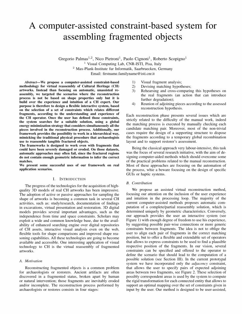
A computer-assisted constraint-based system forassembling fragmented objects
Gregorio Palmas1,2, Nico Pietroni1, Paolo Cignoni1, Roberto Scopigno1
1 Visual Computing Lab, CNR-ISTI, Pisa, Italy2 Max-Plank-Institute fur Informatik, Saarbruecken, Germany
Email: [email protected]
Abstract—We propose a computer-assisted constraint-basedmethodology for virtual reassembly of Cultural Heritage (CH)artworks. Instead than focusing on automatic, unassisted re-assembly, we targeted the scenarios where the reconstructionprocess is not be based on shape properties only but it isbuild over the experience and intuition of a CH expert. Ourpurpose is therefore to design a flexible interactive system, basedon the selection of a set of constraints which relates differentfragments, according to the understanding and experience ofthe CH operator. Once the user has defined those constraints,the system searches for a suitable solution, using a globalenergy minimization strategy that considers simultaneously all thepieces involved in the reconstruction process. Additionally, ourframework provides the possibility to work in a hierarchical way,mimicking the traditional physical procedure that archaeologistsuse to reassemble tangible fractured objects.The frameworks is designed to work even with fragments thatcould have been severely damaged or eroded. On those datasets,automatic approaches may often fail, since the fractured regionsdo not contain enough geometric information to infer the correctmatches.We present some successful uses of our framework on realapplication scenarios.
I. INTRODUCTION
The progress of the technologies for the acquisition of high-quality 3D models of real CH artworks has been impressive.The adoption of active or passive approaches for sampling theshape of artworks is becoming a common task in several CHactivities, such as: study/research, documentation of findingsin excavations, virtual presentation and restoration. 3D digitalmodels provides several important advantages, such as theindependence from time and space constraints. Scholars mayexploit a wide and common knowledge base, due to the avail-ability of enhanced searching engine over digital repositoriesof CH assets, interactive visual analysis even on the web,flexible tools for shape comparisons and improved shape rea-soning capabilities. All these technologies are going to becomeavailable and accessible. One interesting application of visualtechnology to CH is the virtual reassembly of fragmentedartworks.
A. Motivation
Reconstructing fragmented objects is a common problemfor archaeologists or restorers. Ancient artifacts are oftendiscovered in a fragmented status, broken apart by humanor natural intervention; those fragments are inevitably erodedand/or incomplete. The reconstruction process performed byarchaeologists or restores consists in four stages:
1) Visual fragment analysis;2) Devising matching hypotheses;3) Rehearsing and cross-comparing this hypotheses on
the real fragments (an action that can introducefurther degradation);
4) Reunion of adjoining pieces according to the assessedreconstruction hypothesis.
Each reconstruction phase presents several issues which arestrictly related to the difficulty of the manual work, indeedthe matching process is executed by manually checking eachcandidate matching pair. Moreover, most of the non-trivialcases require the design of a supporting structure to disposethe fragments according to a temporary global recombinationlayout and to support restorer’s assessment.
Being the classical approach very labour-intensive, this taskwas the focus of several research initiative, with the aim of de-signing computer-aided methods which should overcome someof the practical problems related to the manual reconstruction.Most of these approaches are focusing on the automation ofthe process, whie a beware focusing on the design of specificGUIs or haptic systems.
B. Contribution
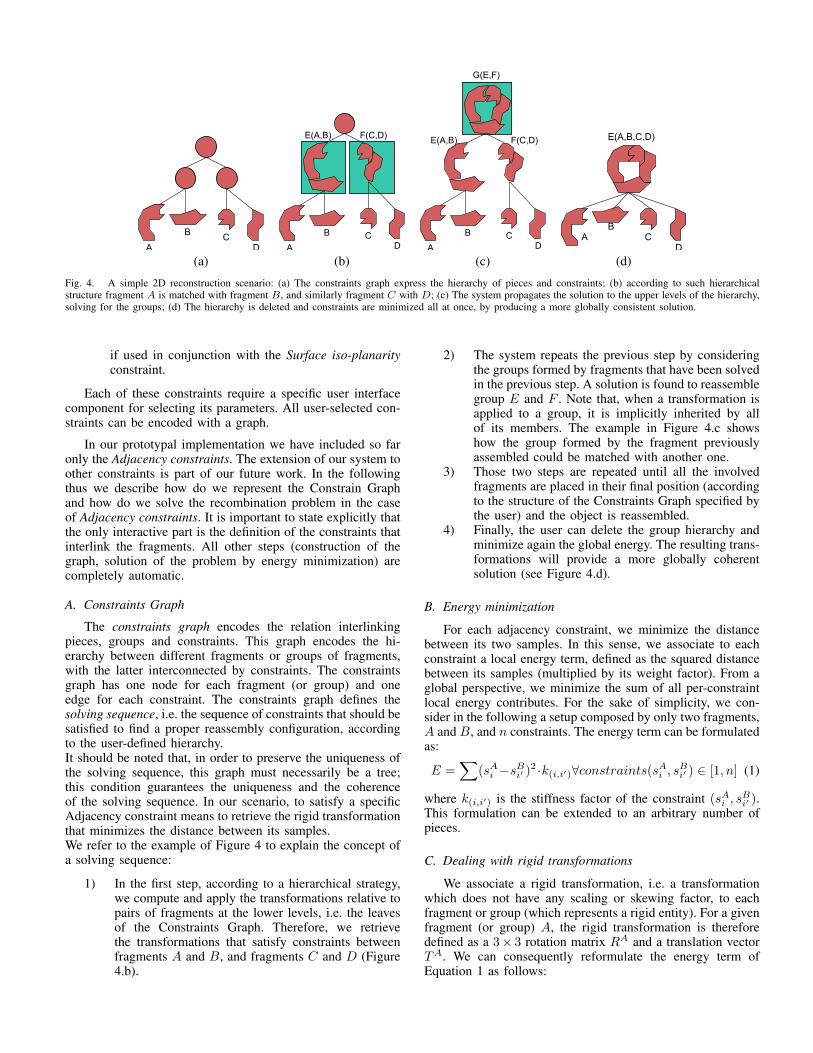
We propose an assisted virtual reconstruction method,focusing our attention on the inclusion of the user experienceand intuition in the processing loop. The majority of thecurrent computer-assisted methods proposes automatic com-putation of a complete/partial reassembly solution, which isdetermined uniquely by geometric characteristics. Conversely,our approach provides the user an interactive system (seeFigure 1) with enough degree of freedom to use his experience,by suggesting possible pair-wise connections or more genericconstraints between fragments. The idea is not to oblige theuser to align each pair of fragments in the correct matchingposition, but to offer a flexible and extendable set of operatorsthat allows to express constraints to be used to find a plausiblerespective position of the fragments. In our vision, severalconstraints can be specified and offered to the operator todefine the scenario that should lead to the computation of apossible solution (see Section III). In the current prototypalsystem we have incorporated only the adjacency constraint,that allows the user to specify pairs of expected adjoiningareas between two fragments, see Figure 2. These selection ofpossibly correspondent areas is used by the system to computethe rigid transformation for each connected entity that allows tosupport an optimal mapping over the set of constraints given ininput by the user. Our method is designed to be user-assisted,
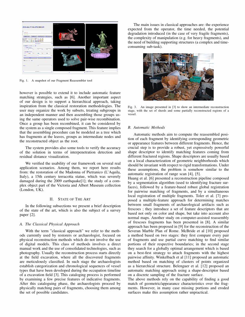
Fig. 1. A snapshot of our Fragment Reassembler tool
however is possible to extend it to include automatic featurematching strategies, such as [6]. Another important aspectof our design is to support a hierarchical approach, takinginspiration from the classical restoration methodologies. Theuser may organize the work by subsets, treating subgroups inan independent manner and then assembling those groups us-ing the same operators used to solve pair-wise recombination.Once a group has been recombined, it can be considered bythe system as a single composed fragment. This feature impliesthat the assembling procedure can be modeled as a tree whichhas fragments at the leaves, groups as intermediate nodes andthe reconstructed object as the root.
The system provides also some tools to verify the accuracyof the solution in terms of interpenetration detection andresidual distance visualization.
We verified the usability of our framework on several realapplication scenarios. Among them, we report here resultsfrom: the restoration of the Madonna of Pietranico (L’Aquila,Italy), a 15th century terracotta statue, which was severelydamaged during the 2009 earthquake[1]; the study of a com-plex object part of the Victoria and Albert Museum collection(London, UK).
II. STATE OF THE ART
In the following subsections we present a brief descriptionof the state of the art, which is also the subject of a surveypaper [2].
A. The Classical Physical Approach
With the term ”classical approach” we refer to the meth-ods currently used by restorers or archaeologist, focused onphysical reconstruction methods which do not involve the useof digital models. This class of methods involves a directmanual work and the use of consolidated technologies, such asphotography. Usually the reconstruction process starts directlyat the field excavation, where all the discovered fragmentsare meticulously classified. In such stage the archaeologistsestablish categorization and chronological sequences of vesseltypes that have been developed during the occupation timelineof a excavation field [3]. This cataloging process is performedby examining a few precise features of indicative fragments.After this cataloguing phase, the archaeologists proceed byphysically matching pairs of fragments, choosing them amongthe set of possible candidates.
The main issues in classical approaches are: the experienceexpected from the operator, the time needed, the potentialdegradation introduced (in the case of very fragile fragments),the complexity of manipulation (e.g. for heavy fragments), andthe need of building supporting structures (a complex and time-consuming sub-task).
Fig. 3. An image presented in [3] to show an intermediate reconstructionstage, with the set of sherds and some partially reconstructed regions of avessel.
B. Automatic Methods
Automatic methods aim to compute the reassembled posi-tion of each fragment by identifying corresponding geometricor appearance features between different fragments. Hence, thecrucial step is to provide a robust, yet expressively powerfulshape descriptor to identify matching features coming fromdifferent fractured regions. Shape descriptors are usually basedon a local characterization of geometric neighborhoods whichshould be invariant with respect to rigid transformations. Underthese assumptions, the problem is somehow similar to theautomatic registration of range scan [4], [5].Huang et al. [6] presented a reconstruction pipeline composedby a segmentation algorithm (used to identifying fracture sur-faces), followed by a feature-based robust global registrationfor pairwise matching of fragments, and by a simultaneouslocal registration of multiple fragments. Toler et al. [7] pro-posed a multiple-feature approach for determining matchesbetween small fragments of archaeological artifacts such asfrescoes ; they introduce a set of feature descriptors that arebased not only on color and shape, but take into account alsonormal maps. Another study on computer-assisted reassemblyof frescoes fragments has been presented in [8]. A similarapproach has been proposed in [9] for the reconstruction of theSeveran Marble Plan of Rome. McBride et al [10] proposeda method based on two stages: they first compare every pairof fragments and use partial curve matching to find similarportions of their respective boundaries; in the second stagethey search for a globally optimal arrangement which is basedon a best-first strategy to attach fragments with the highestpairwise affinity. Winkelbach et al [11] proposed an automaticmethod based on matching of clusters of points organizedas a hierarchical structure. Belenguer et al. [12] proposed anautomatic matching approach using a shape-descriptor basedon a discrete sampling of the fracture surface.The above methods rely on the capability of finding a goodmatch of geometric/appearance characteristics over the frag-ments. However, in many case missing portions and erodedsurfaces make this assumption rather unpractical.
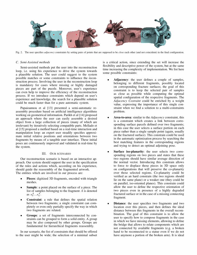
Fig. 2. The user specifies adjacency constraints by setting pairs of points that are supposed to be close each other (and not coincident) in the final configuration.
C. Semi-Assisted methods
Semi-assisted methods put the user into the reconstructionloop, i.e. using his experience to drive the system towardsa plausible solution. The user could suggest to the systempossible matches or some constraints to influence the recon-struction process. Involving the user in the reconstruction loopis mandatory for cases where missing or highly damagedpieces are part of the puzzle. Moreover, user’s experiencecan even help to improve the efficiency of the reconstructionprocess. If we introduce constraints which depend on user’sexperience and knowledge, the search for a plausible solutioncould be much faster than for a pure automatic system.
Papaioannou et al [13] presented a semi-automatic re-assembly procedure based on artificial intelligence algorithmsworking on geometrical information. Parikh et al [14] proposedan approach where the user can easily assemble a desiredobject from a large collection of pieces (many of which areirrelevant) by iteratively selecting compatible parts. Mellado etal [15] proposed a method based on a real-time interaction andmanipulation loop: an expert user steadily specifies approxi-mate initial relative positions and orientations between twofragments by means of a tangible user interface. These initialposes are continuously improved and validated in real-time bythe system.
III. OUR SCENARIO
Our reconstruction scenario is based on an interactive ap-proach. Our system should support the user in the specificationof the rules and actions which, according on his experience,should guide the reassembly of the fragmented artwork.The entities which are involved in our process are:
• Pieces: digitized 3D fragments, encoded with trianglemeshes.
• Sample: a point placed on the surface of a piece. Thelist of samples belonging to the fragment A is denotedas sA
0 ...sAn .
• Constraint: a rule that defines the spatial relationbetween two fragments; a single constraint can com-pletely or even only partially specify the way in whichtwo fragments are related.
• Groups: a set of fragments interconnected by con-straints can be grouped to form a solid entity. A groupmay be also composed by other groups. Groups arefundamental for hierarchical fragments reassembly.
In our scenario, the list of constraints that should be offeredto the user might be wide; the selection of a minimal subset
is a critical action, since extending the set will increase theflexibility and descriptive power of the system, but at the sametime increasing the complexity of implementation. We list heresome possible constraints:
• Adjacency: the user defines a couple of samples,belonging to different fragments, possibly locatedon corresponding fracture surfaces; the goal of thisconstraint is to keep the selected pair of samplesas close as possible while computing the optimalspatial configuration of the respective fragments. TheAdjacency Costraint could be enriched by a weightvalue, expressing the importance of this single con-straint when we find a solution to a multi-constraintsproblem.
• Area-to-area: similar to the Adjacency constraint, thisis a constraint which creates a link between corre-sponding surface parcels defined over two fragments;in this case the user selects a surface portion on eachpiece rather than a single sample point (again, usuallyon the fractured surface). This constrain could be usedin the automatic optimization process by searching thebest matching features in the corresponding regionsand trying to detect an optimal adjoining pose.
• Surface iso-planarity: the user selects two corre-sponding regions on two pieces and states that thesetwo regions should have similar average direction ofthe normal vector. Introducing this constrain allowsto force to displace those pieces in 3D space onlyon configurations that will preserve the co-planarityover those selected regions. Co-planarity could beverified as an hard constrain (the two regions shouldlie on the same plane) or a weaker one (they could beon parallel, iso-oriented planes). This constrain couldallow the user to define the respective orientation oftwo pieces even in presence of a highly degradedfractured surface or in the case of a missing connectingfragment.
• Distance: the user specifies two fragments and twolocation over this pieces, and then defines the idealdistance between this fragments in the overall recom-bination. The goal of this constraint is to allow theuser to specify how to compose fragments in the casein which we have missing elements, allowing to definethe bridge that allows to relate components which arenot connected by available fragments (e.g. a brokenhand to be reconnected to a statue even if we do nothave anymore a portion of the broken arm). It is ideal
A
B CD A
B CD
E(A,B) F(C,D)
A
B CD
E(A,B) F(C,D)
G(E,F)
AB
CD
E(A,B,C,D)
(a) (b) (c) (d)
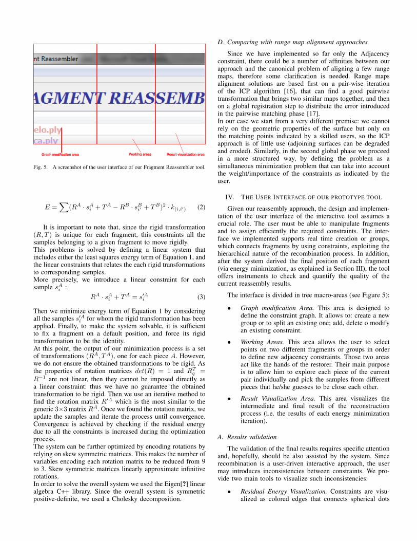
Fig. 4. A simple 2D reconstruction scenario: (a) The constraints graph express the hierarchy of pieces and constraints; (b) according to such hierarchicalstructure fragment A is matched with fragment B, and similarly fragment C with D; (c) The system propagates the solution to the upper levels of the hierarchy,solving for the groups; (d) The hierarchy is deleted and constraints are minimized all at once, by producing a more globally consistent solution.
if used in conjunction with the Surface iso-planarityconstraint.
Each of these constraints require a specific user interfacecomponent for selecting its parameters. All user-selected con-straints can be encoded with a graph.
In our prototypal implementation we have included so faronly the Adjacency constraints. The extension of our system toother constraints is part of our future work. In the followingthus we describe how do we represent the Constrain Graphand how do we solve the recombination problem in the caseof Adjacency constraints. It is important to state explicitly thatthe only interactive part is the definition of the constraints thatinterlink the fragments. All other steps (construction of thegraph, solution of the problem by energy minimization) arecompletely automatic.
A. Constraints Graph
The constraints graph encodes the relation interlinkingpieces, groups and constraints. This graph encodes the hi-erarchy between different fragments or groups of fragments,with the latter interconnected by constraints. The constraintsgraph has one node for each fragment (or group) and oneedge for each constraint. The constraints graph defines thesolving sequence, i.e. the sequence of constraints that should besatisfied to find a proper reassembly configuration, accordingto the user-defined hierarchy.It should be noted that, in order to preserve the uniqueness ofthe solving sequence, this graph must necessarily be a tree;this condition guarantees the uniqueness and the coherenceof the solving sequence. In our scenario, to satisfy a specificAdjacency constraint means to retrieve the rigid transformationthat minimizes the distance between its samples.We refer to the example of Figure 4 to explain the concept ofa solving sequence:
1) In the first step, according to a hierarchical strategy,we compute and apply the transformations relative topairs of fragments at the lower levels, i.e. the leavesof the Constraints Graph. Therefore, we retrievethe transformations that satisfy constraints betweenfragments A and B, and fragments C and D (Figure4.b).
2) The system repeats the previous step by consideringthe groups formed by fragments that have been solvedin the previous step. A solution is found to reassemblegroup E and F . Note that, when a transformation isapplied to a group, it is implicitly inherited by allof its members. The example in Figure 4.c showshow the group formed by the fragment previouslyassembled could be matched with another one.
3) Those two steps are repeated until all the involvedfragments are placed in their final position (accordingto the structure of the Constraints Graph specified bythe user) and the object is reassembled.
4) Finally, the user can delete the group hierarchy andminimize again the global energy. The resulting trans-formations will provide a more globally coherentsolution (see Figure 4.d).
B. Energy minimization
For each adjacency constraint, we minimize the distancebetween its two samples. In this sense, we associate to eachconstraint a local energy term, defined as the squared distancebetween its samples (multiplied by its weight factor). From aglobal perspective, we minimize the sum of all per-constraintlocal energy contributes. For the sake of simplicity, we con-sider in the following a setup composed by only two fragments,A and B, and n constraints. The energy term can be formulatedas:
E =∑
(sAi −sB
i′ )2 ·k(i,i′)∀constraints(sA
i , sBi′ ) ∈ [1, n] (1)
where k(i,i′) is the stiffness factor of the constraint (sAi , sB
i′ ).This formulation can be extended to an arbitrary number ofpieces.
C. Dealing with rigid transformations
We associate a rigid transformation, i.e. a transformationwhich does not have any scaling or skewing factor, to eachfragment or group (which represents a rigid entity). For a givenfragment (or group) A, the rigid transformation is thereforedefined as a 3× 3 rotation matrix RA and a translation vectorTA. We can consequently reformulate the energy term ofEquation 1 as follows:
Graph modification area Working areas Result visualization area
Fig. 5. A screenshot of the user interface of our Fragment Reassembler tool.
E =∑
(RA · sAi + TA −RB · sB
i′ + TB)2 · k(i,i′) (2)
It is important to note that, since the rigid transformation(R, T ) is unique for each fragment, this constraints all thesamples belonging to a given fragment to move rigidly.This problems is solved by defining a linear system thatincludes either the least squares energy term of Equation 1, andthe linear constraints that relates the each rigid transformationsto corresponding samples.More precisely, we introduce a linear constraint for eachsample sA
i :RA · sA
i + TA = s′Ai (3)
Then we minimize energy term of Equation 1 by consideringall the samples s′Ai for whom the rigid transformation has beenapplied. Finally, to make the system solvable, it is sufficientto fix a fragment on a default position, and force its rigidtransformation to be the identity.At this point, the output of our minimization process is a setof transformations (RA, TA), one for each piece A. However,we do not ensure the obtained transformations to be rigid. Asthe properties of rotation matrices det(R) = 1 and RT
q =R−1 are not linear, then they cannot be imposed directly asa linear constraint: thus we have no guarantee the obtainedtransformation to be rigid. Then we use an iterative method tofind the rotation matrix R′A which is the most similar to thegeneric 3×3 matrix RA. Once we found the rotation matrix, weupdate the samples and iterate the process until convergence.Convergence is achieved by checking if the residual energydue to all the constraints is increased during the optimizationprocess.The system can be further optimized by encoding rotations byrelying on skew symmetric matrices. This makes the number ofvariables encoding each rotation matrix to be reduced from 9to 3. Skew symmetric matrices linearly approximate infinitiverotations.In order to solve the overall system we used the Eigen[?] linearalgebra C++ library. Since the overall system is symmetricpositive-definite, we used a Cholesky decomposition.
D. Comparing with range map alignment approaches
Since we have implemented so far only the Adjacencyconstraint, there could be a number of affinities between ourapproach and the canonical problem of aligning a few rangemaps, therefore some clarification is needed. Range mapsalignment solutions are based first on a pair-wise iterationof the ICP algorithm [16], that can find a good pairwisetransformation that brings two similar maps together, and thenon a global registration step to distribute the error introducedin the pairwise matching phase [17].In our case we start from a very different premise: we cannotrely on the geometric properties of the surface but only onthe matching points indicated by a skilled users, so the ICPapproach is of little use (adjoining surfaces can be degradedand eroded). Similarly, in the second global phase we proceedin a more structured way, by defining the problem as asimultaneous minimization problem that can take into accountthe weight/importance of the constraints as indicated by theuser.
IV. THE USER INTERFACE OF OUR PROTOTYPE TOOL
Given our reassembly approach, the design and implemen-tation of the user interface of the interactive tool assumes acrucial role. The user must be able to manipulate fragmentsand to assign efficiently the required constraints. The inter-face we implemented supports real time creation or groups,which connects fragments by using constraints, exploiting thehierarchical nature of the recombination process. In addition,after the system derived the final position of each fragment(via energy minimization, as explained in Section III), the tooloffers instruments to check and quantify the quality of thecurrent reassembly results.
The interface is divided in tree macro-areas (see Figure 5):
• Graph modification Area. This area is designed todefine the constraint graph. It allows to: create a newgroup or to split an existing one; add, delete o modifyan existing constraint.
• Working Areas. This area allows the user to selectpoints on two different fragments or groups in orderto define new adjacency constraints. Those two areasact like the hands of the restorer. Their main purposeis to allow him to explore each piece of the currentpair individually and pick the samples from differentpieces that he/she guesses to be close each other.
• Result Visualization Area. This area visualizes theintermediate and final result of the reconstructionprocess (i.e. the results of each energy minimizationiteration).
A. Results validation
The validation of the final results requires specific attentionand, hopefully, should be also assisted by the system. Sincerecombination is a user-driven interactive approach, the usermay introduces inconsistencies between constraints. We pro-vide two main tools to visualize such inconsistencies:
• Residual Energy Visualization. Constraints are visu-alized as colored edges that connects spherical dots
(samples) in the result visualization area. We associ-ated a color proportional to the residual energy of theconstraint after the minimization process (blue is lowenergy, while red means hight energy).
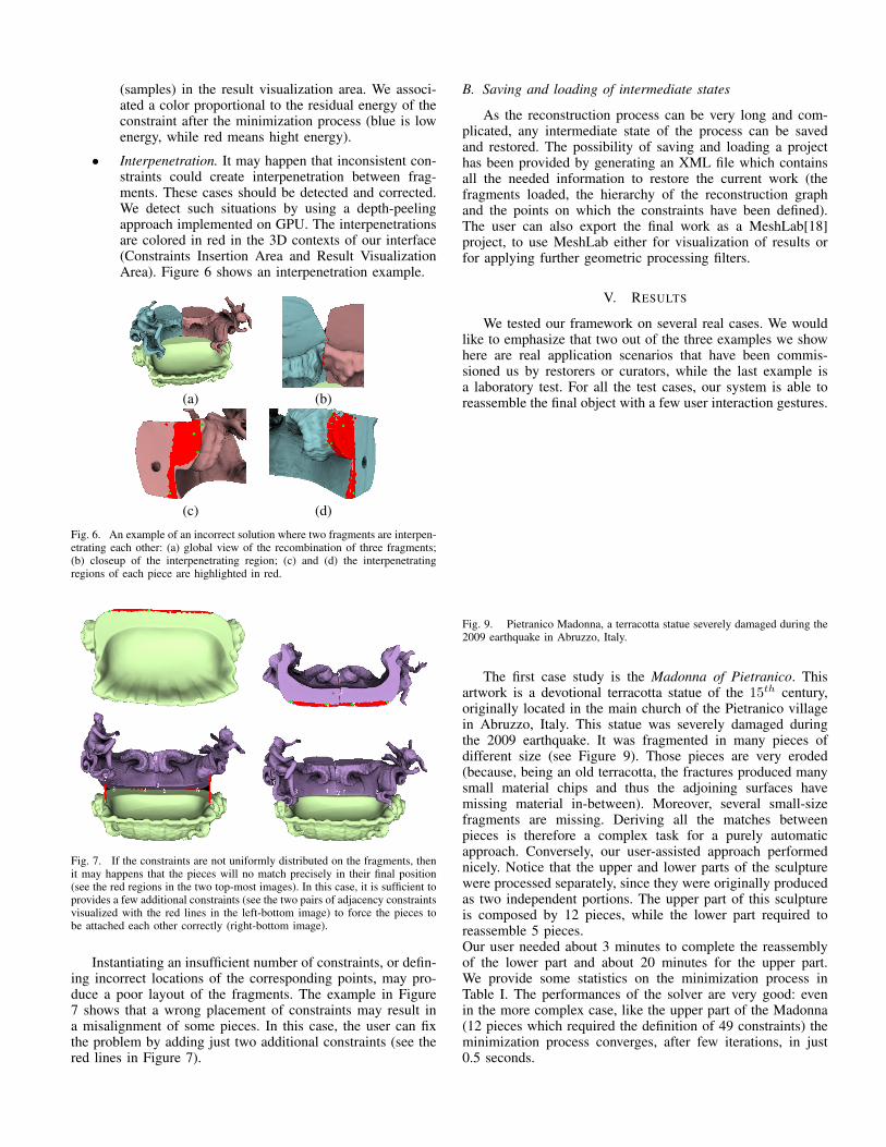
• Interpenetration. It may happen that inconsistent con-straints could create interpenetration between frag-ments. These cases should be detected and corrected.We detect such situations by using a depth-peelingapproach implemented on GPU. The interpenetrationsare colored in red in the 3D contexts of our interface(Constraints Insertion Area and Result VisualizationArea). Figure 6 shows an interpenetration example.
(a) (b)
(c) (d)
Fig. 6. An example of an incorrect solution where two fragments are interpen-etrating each other: (a) global view of the recombination of three fragments;(b) closeup of the interpenetrating region; (c) and (d) the interpenetratingregions of each piece are highlighted in red.
Fig. 7. If the constraints are not uniformly distributed on the fragments, thenit may happens that the pieces will no match precisely in their final position(see the red regions in the two top-most images). In this case, it is sufficient toprovides a few additional constraints (see the two pairs of adjacency constraintsvisualized with the red lines in the left-bottom image) to force the pieces tobe attached each other correctly (right-bottom image).
Instantiating an insufficient number of constraints, or defin-ing incorrect locations of the corresponding points, may pro-duce a poor layout of the fragments. The example in Figure7 shows that a wrong placement of constraints may result ina misalignment of some pieces. In this case, the user can fixthe problem by adding just two additional constraints (see thered lines in Figure 7).
B. Saving and loading of intermediate states
As the reconstruction process can be very long and com-plicated, any intermediate state of the process can be savedand restored. The possibility of saving and loading a projecthas been provided by generating an XML file which containsall the needed information to restore the current work (thefragments loaded, the hierarchy of the reconstruction graphand the points on which the constraints have been defined).The user can also export the final work as a MeshLab[18]project, to use MeshLab either for visualization of results orfor applying further geometric processing filters.
V. RESULTS
We tested our framework on several real cases. We wouldlike to emphasize that two out of the three examples we showhere are real application scenarios that have been commis-sioned us by restorers or curators, while the last example isa laboratory test. For all the test cases, our system is able toreassemble the final object with a few user interaction gestures.
Fig. 9. Pietranico Madonna, a terracotta statue severely damaged during the2009 earthquake in Abruzzo, Italy.
The first case study is the Madonna of Pietranico. Thisartwork is a devotional terracotta statue of the 15th century,originally located in the main church of the Pietranico villagein Abruzzo, Italy. This statue was severely damaged duringthe 2009 earthquake. It was fragmented in many pieces ofdifferent size (see Figure 9). Those pieces are very eroded(because, being an old terracotta, the fractures produced manysmall material chips and thus the adjoining surfaces havemissing material in-between). Moreover, several small-sizefragments are missing. Deriving all the matches betweenpieces is therefore a complex task for a purely automaticapproach. Conversely, our user-assisted approach performednicely. Notice that the upper and lower parts of the sculpturewere processed separately, since they were originally producedas two independent portions. The upper part of this sculptureis composed by 12 pieces, while the lower part required toreassemble 5 pieces.Our user needed about 3 minutes to complete the reassemblyof the lower part and about 20 minutes for the upper part.We provide some statistics on the minimization process inTable I. The performances of the solver are very good: evenin the more complex case, like the upper part of the Madonna(12 pieces which required the definition of 49 constraints) theminimization process converges, after few iterations, in just0.5 seconds.
(a) (b) (c) (d)
(e) (f) (g) (h)
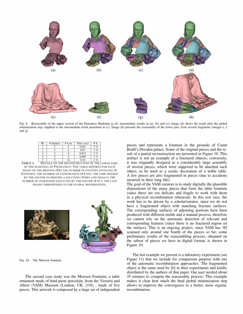
Fig. 8. Reassembly of the upper section of the Pietranico Madonna (a..d): intermediate results in (a), (b) and (c); image (d) shows the result after the globalminimization step, tapplied to the intermediate result presented in (c). Image (h) presents the reassembly of the lower part, from several fragments (images e, fand g).
Ph. # Entities # Con Time (sec) # It.1 2 4 0.021 5 %2 2 4 0.01 3 %3 2 4 0.013 3 %4 2 4 0.009 2 %5 5 16 0.16 3 %
TABLE I. DETAILS ON THE RECONSTRUCTION OF THE LOWER PARTOF THE MADONNA OF PIETRANICO: THE TABLE REPORTS FOR EACH
PHASE OF THE PROCESS (PH) THE NUMBER OF ENTITIES INVOLVED (#ENTITIES), THE NUMBER OF CONSTRAINTS (# CON), THE TIME NEEDED
BY THE SOLVER TO PROVIDE A SOLUTION (TIME) AND FINALLY THENUMBER OF ITERATIONS EXECUTED BY THE SOLVER (# IT.); THE LAST
PHASE CORRESPONDS TO THE GLOBAL MINIMIZATION.
Fig. 10. The Meissen fountain.
The second case study was the Meissen Fountain, a tableornament made of hard-paste porcelain, from the Victoria andAlbert (VAM) Museum (London, UK, [19]) , made of fivepieces. This artwork is composed by a large set of independent
pieces and represents a fountain in the grounds of CountBruhl’s Dresden palace. Some of the original pieces and the re-sult of a partial reconstruction are presented in Figure 10. Thisartifact is not an example of a fractured objects; conversely,it was originally designed as a considerably large assemblyof several pieces, which were supposed to be attached eachothers, to be used as a scenic decoration of a noble table.A few pieces are also fragmented in pieces (due to accidentsincurred in their long life).The goal of the VAM curators is to study digitally the plausibledispositions of the many pieces that form the table fountain(since these are too delicate and fragile to work with themin a physical recombination rehearsal). In this test case, thework has to be driven by a scholar/curator, since we do nothave a fragmented object with matching fracture surfaces.The corresponding surfaces of adjoining portions have beenproduced with different molds and a manual process, thereforewe cannot rely on the automatic detection of relevant andcorresponding features (since there is no fractured region onthe surface). This is an ongoing project, since VAM has 3Dscanned only around one fourth of the pieces so far; somepreliminary results of the reassembling process, obtained onthe subset of pieces we have in digital format, is shown inFigure 10.
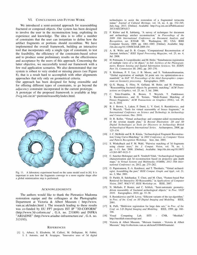
The last example we present is a laboratory experiment (seeFigure 11) that we include for comparison purpose with oneof the automatic recombination approaches. The fragmentedobject is the same used by [6] in their experiments and kindlydistributed by the authors of that paper. Our user needed about35 minutes to compete the reassembly process. This examplemakes it clear how much the final global minimization stepallows to improve the convergence to a better, more regular,recombination.
VI. CONCLUSIONS AND FUTURE WORK
We introduced a semi-assisted approach for reassemblingfractured or composed objects. Our system has been designedto involve the user in the reconstruction loop, exploiting itsexperience and knowledge. The idea is to offer a numberof constraints that the user can instantiate to define how theartifact fragments or portions should recombine. We haveimplemented the overall framework, building an interactivetool that incorporates only a single type of constraint, to testthe feasibility, the efficiency of the constraints-based solverand to produce some preliminary results on the effectivenessand acceptance by the users of this approach. Concerning thelatter objective, we successfully tested our framework with afew real application scenarios. We also demonstrated that oursystem is robust to very eroded or missing pieces (see Figure8), that is a result hard to accomplish with other alignmentsapproaches that rely only on geometrical criteria.Our approach has been designed for being extensible andfor offering different types of constraints, to go beyond theadjacency constraint incorporated in the current prototype.A prototype of the proposed framework is available at http://vcg.isti.cnr.it/∼pietroni/reassebly/index.html.
Fig. 11. A laboratory experiment based on the same model used in [6]. It isimportant to note how the fragments converge to a more regular shape aftera global minimization step is performed.
ACKNOWLEDGMENTS
The authors would like to thank the Pietranico Madonnarestoration equipe and the colleagues at the PhotographicDepartment at Victoria & Albert Museum ( http://www.vam.ac.uk/index.html ). The research leading to these resultswas co-funded by EU FP7 projects IST IP ”3D-COFORM”(http://www.3d-coform.eu/ , G.A. no. 231809) and INFRA”ARIADNE” (http://www.ariadne-infrastructure.eu/ , G.A. no.313193).
REFERENCES
[1] L. Arbace, S. Elisabetta, M. Callieri, M. Dellepiane, M. Fabbri,I. I. Antonio, and R. Scopigno, “Innovative uses of 3d digital
technologies to assist the restoration of a fragmented terracottastatue,” Journal of Cultural Heritage, vol. 14, no. 4, pp. 332–345,July-Aug. 2013. [Online]. Available: http://vcg.isti.cnr.it/Publications/2013/AECDFAS13
[2] F. Kleber and R. Sablatnig, “A survey of techniques for documentand archaeology artefact reconstruction,” in Proceedings of the2009 10th International Conference on Document Analysis andRecognition, ser. ICDAR ’09. Washington, DC, USA: IEEEComputer Society, 2009, pp. 1061–1065. [Online]. Available: http://dx.doi.org/10.1109/ICDAR.2009.154
[3] A. R. Willis and D. B. Cooper, “Computational Reconstruction ofAncient Artifacts,” IEEE Signal Processing Magazine, vol. 25, no. 4,Jul. 2008.
[4] H. Pottmann, S. Leopoldseder, and M. Hofer, “Simultaneous registrationof multiple views of a 3d object,” in Intl. Archives of the Photogram-metry, Remote Sensing and Spatial Information Sciences, Vol. XXXIV,Part 3A, Commission III, 2002, pp. 265–270.
[5] S. Krishnan, P. Y. Lee, J. B. Moore, and S. Venkatasubramanian,“Global registration of multiple 3d point sets via optimization-on-a-manifold,” in SGP ’05 Proceedings of the third Eurographics sympo-sium on Geometry processing. Eurographics, 2005.
[6] Q.-X. Huang, S. Flory, N. Gelfand, M. Hofer, and H. Pottmann,“Reassembling fractured objects by geometric matching,” ACM Trans-actions on Graphics, vol. 25, no. 3, Jul. 2006.
[7] C. Toler-Franklin, B. Brown, T. Weyrich, T. Funkhouser,S. Rusinkiewicz, and D. Texture, “Multi-Feature Matching ofFresco Fragments,” ACM Transactions on Graphics (TOG), vol. 29,no. 6, 2010.
[8] B. J. Brown, L. Laken, P. Dutre, L. V. Gool, S. Rusinkiewicz, andT. Weyrich, “Tools for virtual reassembly of fresco fragments,” inInternational Conference on Science and Technology in Archaeologyand Conservations, Dec. 2010.
[9] D. R. Koller, “Virtual archaeology and computer-aided reconstructionof the severan marple plan,” in Beyond Illustration: 2D and 3DDigital Technologies as Tools for Discovery in Archaeology BritishArchaeological Reports International Series. Archaeopress, 2008, pp.125–134.
[10] J. C. McBride and B. B. Kimia, “Archaeological Fragment Reconstruc-tion Using Curve-Matching,” in 2003 Conference on Computer Visionand Pattern Recognition Workshop. Ieee, Jun. 2003.
[11] S. Winkelbach and F. M. Wahl, “Pairwise matching of 3d fragmentsusing cluster trees,” Int. J. Comput. Vision, vol. 78, no. 1,pp. 1–13, Jun. 2008. [Online]. Available: http://dx.doi.org/10.1007/s11263-007-0121-5
[12] C. Sanchez-Belenguer and E. Vendrell-Vidal, “Archaeological fragmentcharacterization and 3d reconstruction based on projective gpu depthmaps,” in Virtual Systems and Multimedia (VSMM), 2012 18th Inter-national Conference on, 2012, pp. 275–282.
[13] G. Papaioannou, E.-A. Karabassi, and T. Theoharis, “Virtual archaeol-ogist: Assembling the past,” IEEE Comput. Graph. and Appl., vol. 21,no. 2, Mar. 2001.
[14] D. Parikh, R. Sukthankar, T. Chen, and M. Chen, “Feature-based PartRetrieval for Interactive 3D Reassembly,” in Applications of ComputerVision, 2007. WACV’07. IEEE Workshop on. IEEE, 2007.
[15] N. Mellado, P. Reuter, and C. Schlick, “Semi-automatic geometry-driven reassembly of fractured archeological objects,” in Proc. VAST2010. Eurographics, 2010, pp. 33–38.
[16] S. Rusinkiewicz and M. Levoy, “Efficient variants of the icp algorithm,”in Proc. of Int. Conf. on 3D Digital Imaging and Modeling. IEEE,2001.
[17] K. Pulli, “Multiview registration for large data sets,” in Proc. of Int.Conf. on 3-D Digital Imaging and Modeling. IEEE, 1999, pp. 160–168.
[18] Visual Computing Lab, ISTI - CNR, “Meshlab,”http://meshlab.sourceforge.net/.
[19] Victoria & Albert Museum, “Meissen fountain - Victoria & AlbertMuseum,” http://collections.vam.ac.uk/item/O10640/fountain/.