Embed Size (px)
Citation preview
1
A constant-force bistable mechanism for force regulationand overload protection
Huy-Tuan Pham, Dung-An Wang*
Graduate Institute of Precision Engineering, National Chung Hsing University, Taichung40227, Taiwan, ROC
Abstract
A novel constant-force bistable mechanism (CFBM) allowing constant contact
force and overload protection is developed. When a device equipped with a CFBM is
loaded by an unknown force exceeding a critical force of the CFBM, the CFBM can
snap to its other stable equilibrium state to safeguard the device. The bistability of the
mechanism originates from combined compression and bending of the beam structures.
Finite element analyses are used to characterize the constant-force behavior and
bistability of the mechanism under static loading. A design formulation is proposed to
find the CFBM shape for a specified displacement range with constant output force of
the mechanism. Prototypes of the CFBM are fabricated and tested. The characteristics
of the CFBM predicted by theory are verified by experiments. Using the CFBM,
sophisticated sensors and control system for force regulation of machining systems can
be eliminated.
Keywords: Bistable; constant-force mechanism; overload protection.
____________* Corresponding author: Tel.:+886-4-22840531 ext. 365; fax:+886-4-22858362
E-mail address: [email protected] (D.-A. Wang).
2
1. Introduction
Responding to the increasing needs in many systems where a variable output
force is undesirable, mechanisms which provide a near-constant output force over a
prescribed deflection range have been developed and are defined as constant-force
mechanisms (CFMs). These mechanisms have been gaining more and more attention in
recent years [1-5]. CFMs can be designed for concrete testing equipment [1], exercise
machines [2] and electrical contacts [3]. A constant-force actuator based on dielectric
elastomers is proposed by Berselli et al. [4] for applications in robotics and mechatronics.
Lan et al. [5] developed a compliant CFM for force regulation of robot end-effectors
operating in an unknown environment.
CFMs can be utilized in systems to reduce the need for complex control
algorithms and feedback loops [6, 7]. Without sophisticated control systems, CFMs
made of passive mechanisms may minimize control effort and reduce cost without losing
precision. CFMs have been developed by various investigators [8-12]. Pedersen et al. [8]
used topology and size optimization to design a transmission mechanism which converts
the constant stiffness of an actuator into constant output force. Weight et al. [9] proposed
a CFM composed of a bent beam and a cam for electrical contacts in personal digital
assistant (PDA) dock stations to improve the reliability of high-cycle electrical
connectors. Their beam and cam combination provides the strain energy storage device
necessary for constant force behavior. Boyle et al. [10] presented a CFM consisting of a
rigid link, a flexible segment and a slider. His compliant CFM offers the possibility of a
new type of spring element for a variety of applications. Nahar and Sugar [11] designed
a double-slider CFM, where two springs are attached to the sliders. They also proposed
the design of a micro compliant slider-crank CFM. However, in order to facilitate these
3
mechanisms in microelectromechanical system (MEMS) devices, monolithic compliant
mechanisms which can be fabricated by microfabrication technologies are favored over
the macro devices. With fewer movable joints, use of compliant mechanisms results in
reduced wear, reduced need for lubrication, and an increased mechanism precision [12].
When integrated with a bistable mechanism, the CFM can have the potential
applications in force regulation and overload protection. Here, the CFM with the added
function of bistability is termed as a constant-force bistable mechanism (CFBM). In
some applications such as micro-ultrasonic machining, a variation in contact force would
cause extreme tool wear and worsen the micromachining accuracy, and the accidental
overloading could break the tool easily [13]. The incorporation of CFBM into these
micro machining stations could help to regulate the output force to accommodate for the
variation in surface roughness and preserve a stable contact force. When the micro tool is
suddenly loaded by an unknown force exceeding a critical value of the CFBM, the
CFBM can snap to its other stable equilibrium state to safeguard the device. Without
resorting to force sensors, controllers and actuators, the CFBM can be effective to protect
the micro machining system from surface variation of unknown/harsh environment.
This paper describes a design of a compliant CFBM. The bending of elastic
beams of the mechanism is exploited to provide the constant output force over a range of
input displacements. Bistability is provided by buckling of curved-beam structures of the
mechanism. The design is based on the compliant bistable mechanisms reported by
Wang et al. [14] and Qiu et al. [15], where the bistability originates from combined
compression and bending of a chevron-type mechanism consisting of straight beams and
flexible hinges [14] or of a double curved-beam structure with carefully selected
4
geometries [15]. The proposed CFBM has a curved-beam structure embedded in a
chevron-type mechanism. An optimization method is used to design the CFBMs. Finite
element analyses are carried out to evaluate the mechanical behaviors of the design
obtained by the optimization procedure. Prototypes of the device are fabricated using a
milling process. Experiments are performed to demonstrate the effectiveness of the
CFBM.
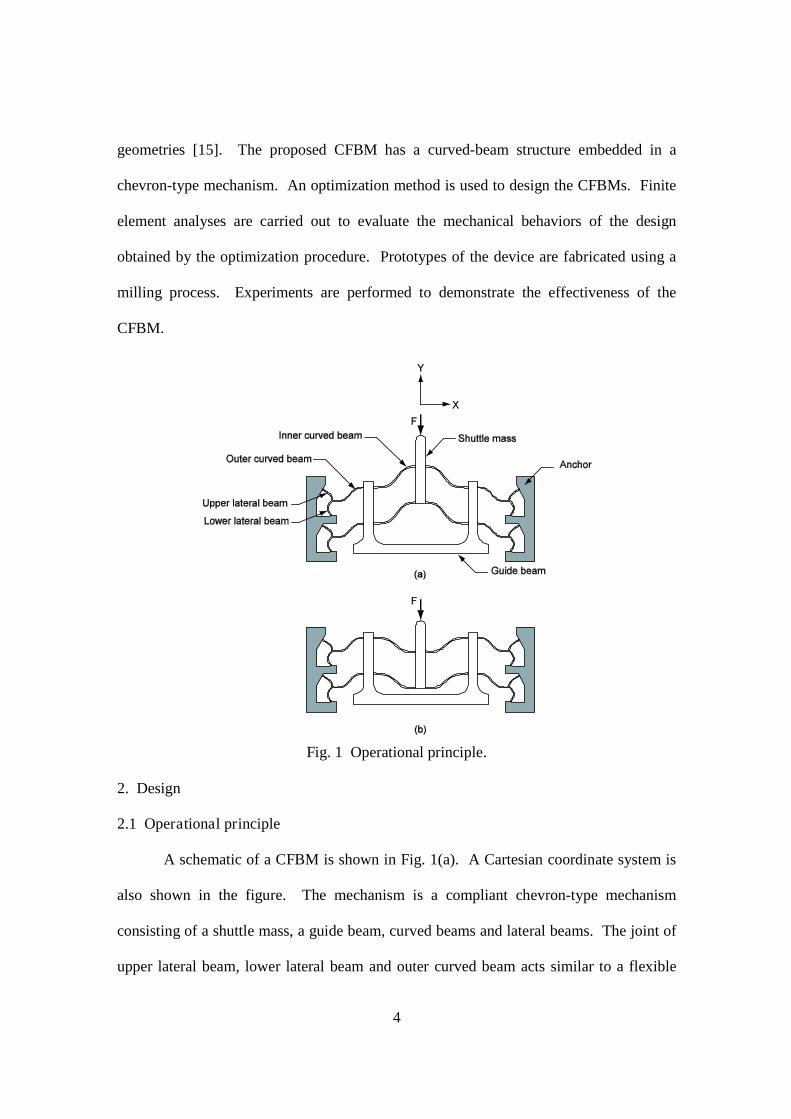
Fig. 1 Operational principle.
2. Design
2.1 Operational principle
A schematic of a CFBM is shown in Fig. 1(a). A Cartesian coordinate system is
also shown in the figure. The mechanism is a compliant chevron-type mechanism
consisting of a shuttle mass, a guide beam, curved beams and lateral beams. The joint of
upper lateral beam, lower lateral beam and outer curved beam acts similar to a flexible
5
hinge and facilitates the rotation of the CFBM. The assembly of the upper lateral beam,
lower lateral beam and outer curved beam is termed as “flexible hinge.” The guide beam
is employed to prevent the mechanism from twisting during operation, and is designed to
be stiff. Upon the application of a force F to the shuttle mass, the lateral beams and outer
curved beams deflect initially, storing the strain energy. As the CFBM deflects further,
the bending energy in the flexible hinges and inner curved beams increases. While the
compression energy in the inner curved beams increases to a maximum at a certain
displacement of the mechanism, critical displacement of the CFBM, but then decreases;
the mechanism snaps towards its second stable equilibrium state. Fig. 1(a) and (b) show
the first and second stable equilibrium state of the mechanism, respectively.
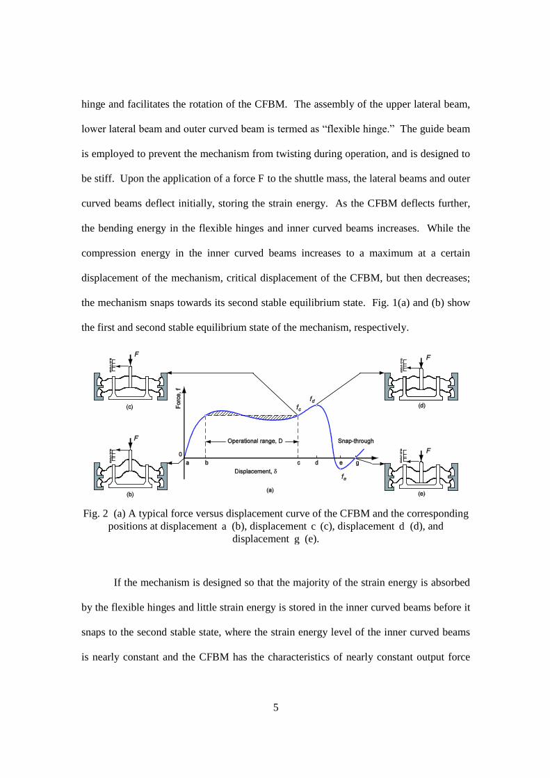
Fig. 2 (a) A typical force versus displacement curve of the CFBM and the correspondingpositions at displacement a (b), displacement c (c), displacement d (d), and
displacement g (e).
If the mechanism is designed so that the majority of the strain energy is absorbed
by the flexible hinges and little strain energy is stored in the inner curved beams before it
snaps to the second stable state, where the strain energy level of the inner curved beams
is nearly constant and the CFBM has the characteristics of nearly constant output force
6
over a range of displacement. Fig. 2(a) shows a typical output force versus displacement
(f-) curve of the CFBM. Fig. 2(b-e) illustrates a four-step operation of the mechanism.
First, a force F is applied to the mechanism through the shuttle mass (see Fig. 2(b)) to
deflect the flexible hinge. When the deflection of the shuttle mass is within the interval
of = b to = c , the mechanism generates a nearly constant output force over this
range of displacement, hence defined as operational range, D (see Fig. 2(a)). The
maximum output force df occurs at the displacement = d (see Fig. 2(d)). ef is the
minimum output force of the CFBM and has a negative value (see Fig. 2(a)). When the
force applied to the mechanism F is greater than df , the mechanism moves towards its
second stable position g (see Fig. 2(e)), where the output force of the CFBM is zero. The
CFBM can not only serve as a transmission mechanism downstream of a device if the
device is to be used in constant force applications [8], but also provide a simple means of
protection of the device in the event of mechanical shock/sudden overloading.
7
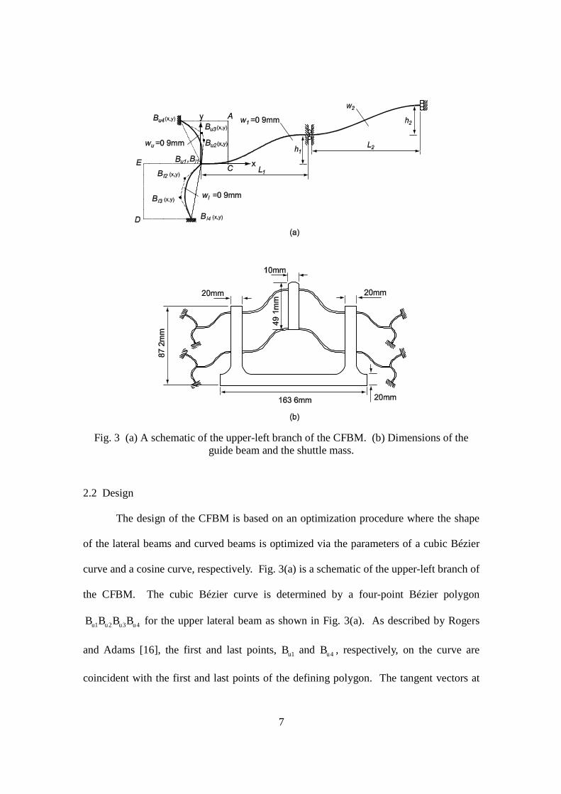
Fig. 3 (a) A schematic of the upper-left branch of the CFBM. (b) Dimensions of theguide beam and the shuttle mass.
2.2 Design
The design of the CFBM is based on an optimization procedure where the shape
of the lateral beams and curved beams is optimized via the parameters of a cubic Bézier
curve and a cosine curve, respectively. Fig. 3(a) is a schematic of the upper-left branch of
the CFBM. The cubic Bézier curve is determined by a four-point Bézier polygon
4321 uuuu BBBB for the upper lateral beam as shown in Fig. 3(a). As described by Rogers
and Adams [16], the first and last points, 1uB and 4uB , respectively, on the curve are
coincident with the first and last points of the defining polygon. The tangent vectors at
8
the ends of the curve have the same directions as the first and last polygon spans,
respectively. The parametric cubic Bézier curve for the upper lateral beam is given by
[17]
10)1(3)1(3)1()(
4
3
2
1
3223
t
PPPP
tttttttP
u
u
u
u
(1)
where t is the parameter, P is the position vector of a point on the curve, and uiP is the
position vector of the point uiB . The shape of the upper lateral beam is optimized by
allowing points 2uB and 3uB to move in the space enclosed by the dotted quadrilateral
ACBB uu 41 in Fig. 3(a). The position of the point 1uB is fixed, and the Cartesian
coordinates ),( yx of the points 2uB , 3uB and 4uB are design variables. The shape of the
lower lateral beam is optimized similarly to the upper lateral beam.
The shape of the curved beams is
i
rir L
xhy
cos1
2(2)
where ),( rr yx is the position vector with the reference origin at the left end of the curved
beams. L and h are the span and apex height of the curved beams, respectively. The
subscript i = 1 and 2 refer to the outer and inner curved beams, respectively. The widths
of the lateral beams and outer curved beams are fixed as 0.9 mm. Therefore, the shape of
the outer curved beams is determined by the design variables 1L and 1h , and the shape of
the inner curved beams is determined by the design variables 2L , 2h , and 2w . The out-
of-plane thickness of the lateral beams and curved beams is taken as 5.0 mm. Hence, the
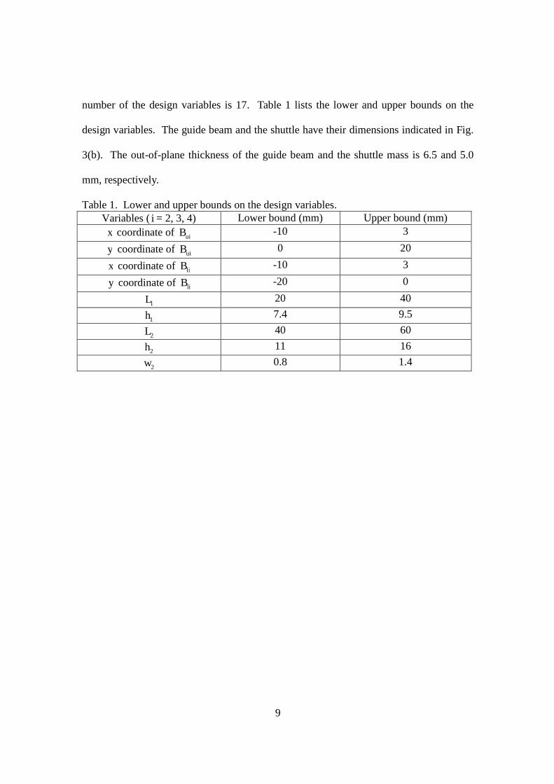
9
number of the design variables is 17. Table 1 lists the lower and upper bounds on the
design variables. The guide beam and the shuttle have their dimensions indicated in Fig.
3(b). The out-of-plane thickness of the guide beam and the shuttle mass is 6.5 and 5.0
mm, respectively.
Table 1. Lower and upper bounds on the design variables.Variables ( i = 2, 3, 4) Lower bound (mm) Upper bound (mm)
x coordinate of uiB -10 3
y coordinate of uiB 0 20
x coordinate of liB -10 3
y coordinate of liB -20 0
1L 20 40
1h 7.4 9.5
2L 40 60
2h 11 16
2w 0.8 1.4
10
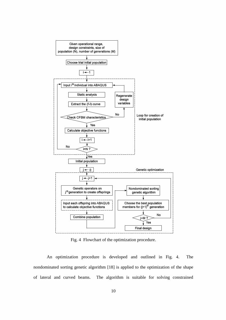
Fig. 4 Flowchart of the optimization procedure.
An optimization procedure is developed and outlined in Fig. 4. The
nondominated sorting genetic algorithm [18] is applied to the optimization of the shape
of lateral and curved beams. The algorithm is suitable for solving constrained
11
multiobjective problems. The efficiency of the nondominated sorting genetic algorithm
lies in a way multiple objectives are reduced to a dummy fitness function using
nondominated sorting procedure [19]. Let )(XF , defined on the design space X , be an
objective space, and XX i . If a vector )( 1XF is partially less than another vector
)( 2XF , we say that the solution )( 1XF dominates )( 2XF , where no value of )( 2XF is
less than )( 1XF and at least one value of )( 2XF is strictly greater than )( 1XF . The
optimal solutions to a multiobjective minimization problem can be taken as the
nondominated solutions. In the optimization process as shown in Fig. 4, initially, the
displacement c , the operational range D , constraints on the design variables, number of
generations, and size of populations are specified. The objective functions of the
optimization problem are
c
b c dffMin
2 (3)
1 e
df
fMin (4)
SffMin
c
d (5)
where cf , df , and ef are the output forces of the CFBM at the displacements of c , d ,
and e , respectively, and S is defined as the specified ratio of the output force df to cf .
The purpose of Eq. (3) is to minimize the fluctuation of the output force f compared to
cf . The formulation of Eq. (3) is similar to that adopted by Meaders and Mattson [3].
As shown in Fig. 2(a), when the shaded area is smaller, the f-curve in the operational
range gets flatter and a nearly constant output force can be obtained [3]. The objective
function of Eq. (4) is selected for assurance of a high level of bistability of the CFBM,
12
where the sign of the df and ef must be opposite and their absolute values must be as
close as possible. The objective function of Eq. (5) is formulated in a way to have the
flexibility for specifying the ratio of df to cf . A higher value of S indicates a higher
value of df is required for snap-through of the CFBM. The value of S is taken as 1.2 in
this investigation.
Due to the geometry complexity, large motions and flexible beam behaviors of
the CFBM, the output force versus displacement (f-) curve of the CFBM may not be
calculated analytically. Finite element method can be used to analyze geometrically
nonlinear behaviors of the mechanism, and is also suitable to model finite axial strain and
transverse shear deformation of stout as well as slender beams of the various beam
geometries generated during the optimization process. Finite element analysis by a
commercial software ABAQUS [20] is utilized to obtain the f-curve. The genetic
algorithm optimization procedure used in this investigation is programmed with the
commercial software MATLAB 7.0. The genetic algorithm, the design variables and the
variable constraints are written in a script file of MATLAB. An ABAQUS text file for
the static analysis to obtain the f-curve is created by the MATLAB file. The output of
the ABAQUS static analysis is saved in a text file. The values of the output forces and
the corresponding displacements of the CFBM are obtained from the f-curve, and are
used to calculate the values of the objective functions for the optimization process. The
coordinates of the positions of the lateral and curved beams are also created in the script
file of MATLAB.
13
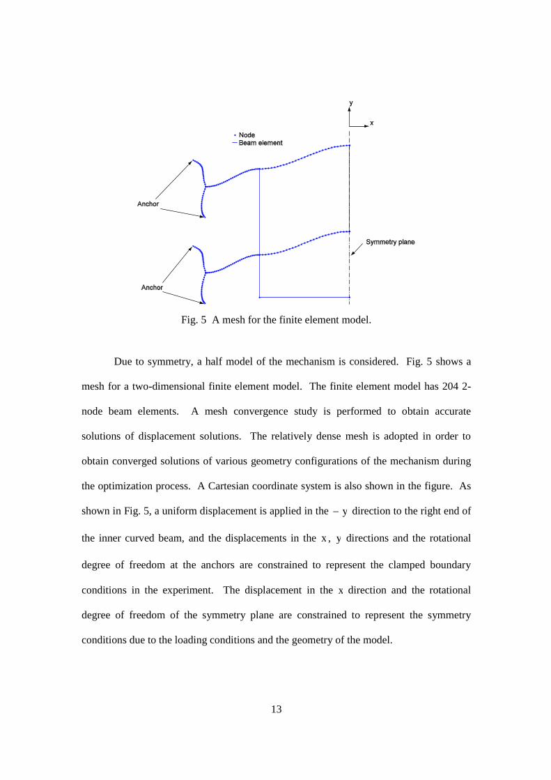
Fig. 5 A mesh for the finite element model.
Due to symmetry, a half model of the mechanism is considered. Fig. 5 shows a
mesh for a two-dimensional finite element model. The finite element model has 204 2-
node beam elements. A mesh convergence study is performed to obtain accurate
solutions of displacement solutions. The relatively dense mesh is adopted in order to
obtain converged solutions of various geometry configurations of the mechanism during
the optimization process. A Cartesian coordinate system is also shown in the figure. As
shown in Fig. 5, a uniform displacement is applied in the y direction to the right end of
the inner curved beam, and the displacements in the x , y directions and the rotational
degree of freedom at the anchors are constrained to represent the clamped boundary
conditions in the experiment. The displacement in the x direction and the rotational
degree of freedom of the symmetry plane are constrained to represent the symmetry
conditions due to the loading conditions and the geometry of the model.
14
In this investigation, the beams are assumed to be linear elastic materials. A
polyoxymethylene (POM) material is used for the CFBM. Five tensile test specimens of
the POM material are cut into the form of standard dumbbell-shaped test specimens
following the ASTM D638-10 test standard for plastic sheeting. Based on the measured
engineering stress - engineering strain curves, the average of theYoung’s modulus of the
POM material is 2.5 GPa. The Poisson’s ratio of the POM is taken as 0.25 [21]. The
commercial finite element program ABAQUS is employed to perform the computations.
2-node beam element B21H is used for the finite element model. B21H is recommended
for geometrically nonlinear analyses when the beam undergoes large motions and is very
flexible [20]. B21H can model finite axial strain and transverse shear deformation of
stout as well as slender beams of the various beam geometries generated during the
optimization process.
2.3 Optimization
In the optimization process, the number of generations, N, is set to be 20, and the
population of each generation is taken as 20. The values of the displacement c and the
the operational range D are specified as 14 mm and 7 mm, respectively. A static
analysis of each population is performed in order to find its f-curve. This optimum
design of the CFBM using the 17 design variables is obtained by the optimization
procedure outlined in Fig. 4. Table 2 lists the values of the design variables of the
optimum design. Fig. 6(a) shows the f-curve of the optimum design of the CFBM,
where b = 7.00 mm, c = 14.00 mm, d = 17.25 mm, g = 23.46 mm, bf = 10.74 N, cf
= 11.09 N, and df = 13.19 N. Therefore, the operational range, displacement between b
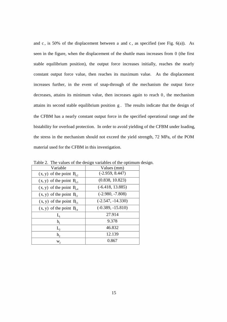
15
and c , is 50% of the displacement between a and c , as specified (see Fig. 6(a)). As
seen in the figure, when the displacement of the shuttle mass increases from 0 (the first
stable equilibrium position), the output force increases initially, reaches the nearly
constant output force value, then reaches its maximum value. As the displacement
increases further, in the event of snap-through of the mechanism the output force
decreases, attains its minimum value, then increases again to reach 0 , the mechanism
attains its second stable equilibrium position g . The results indicate that the design of
the CFBM has a nearly constant output force in the specified operational range and the
bistability for overload protection. In order to avoid yielding of the CFBM under loading,
the stress in the mechanism should not exceed the yield strength, 72 MPa, of the POM
material used for the CFBM in this investigation.
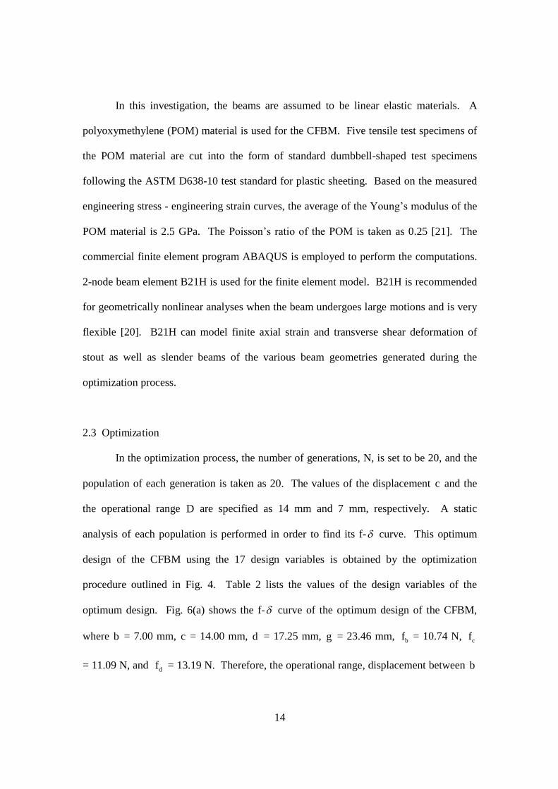
Table 2. The values of the design variables of the optimum design.Variable Values (mm)
),( yx of the point 2uB (-2.959, 8.447)
),( yx of the point 3uB (0.838, 10.823)
),( yx of the point 4uB (-6.418, 13.885)
),( yx of the point 2lB (-2.980, -7.808)
),( yx of the point 3lB (-2.547, -14.330)
),( yx of the point 4lB (-0.389, -15.810)
1L 27.914
1h 9.378
2L 46.832
2h 12.139
2w 0.867
16
Fig. 6 (a) A f-curve; (b) strain energy curve based on a finite element model of theoptimized solution.
Fig. 6(b) shows the strain energy curves as functions of the displacement of the
optimum design. When the displacement of the mechanism increases, the strain energy
of the flexible hinge increases, and the strain energy of the inner curved beam increases
slightly, then reaches an almost constant value. As the displacement of the mechanism
increases further before the mechanism snaps to the second stable state, the majority of
the strain energy is absorbed by the flexible hinge, where the CFBM has the
characteristics of nearly constant output force over a range of displacement. As the
CFBM deflects further, the strain energy in the flexible hinge and inner curved beam
17
increases. As the displacement of the mechanism increases beyond a certain value,
where the CFBM has the maximum output force, the strain energy of the flexible hinge
drops suddenly and the strain energy of the inner curved beam increases abruptly. While
the compression strain energy in the inner curved beam increases to a maximum; the
mechanism snaps towards its second stable equilibrium state. After the snap-through of
the CFBM, the strain energy of the flexible hinge is nearly zero and the strain energy of
the mechanism attains a local minimum value, corresponding to its second stable
equilibrium position.
The simple static analyses of the CFBM are employed in order to obtain the f-
curve of the mechanism in the design stage. As shown in Fig. 6(a), the f-curve of the
CFBM is highly nonlinear, and the finite element model is required to model this
nonlinear force-displacement relation of the mechanism. The nonlinearities are due to
the post-buckling behavior and geometric nonlinearity.
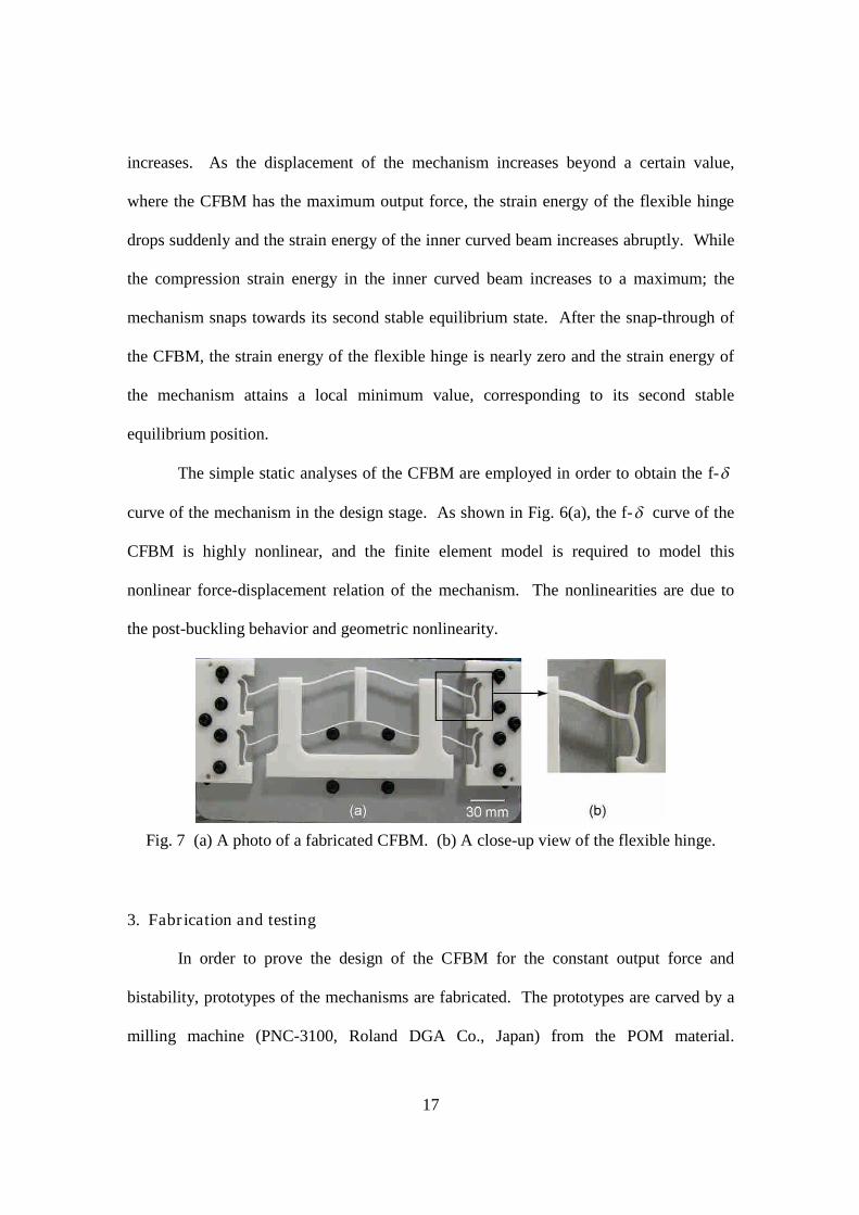
Fig. 7 (a) A photo of a fabricated CFBM. (b) A close-up view of the flexible hinge.
3. Fabrication and testing
In order to prove the design of the CFBM for the constant output force and
bistability, prototypes of the mechanisms are fabricated. The prototypes are carved by a
milling machine (PNC-3100, Roland DGA Co., Japan) from the POM material.
18
Dimensions of the prototypes are based on the optimal design parameters obtained from
the optimization process. Fig. 7(a) is a photo of a fabricated CFBM. Fig. 7(b) is a close
up view of the flexible hinge.
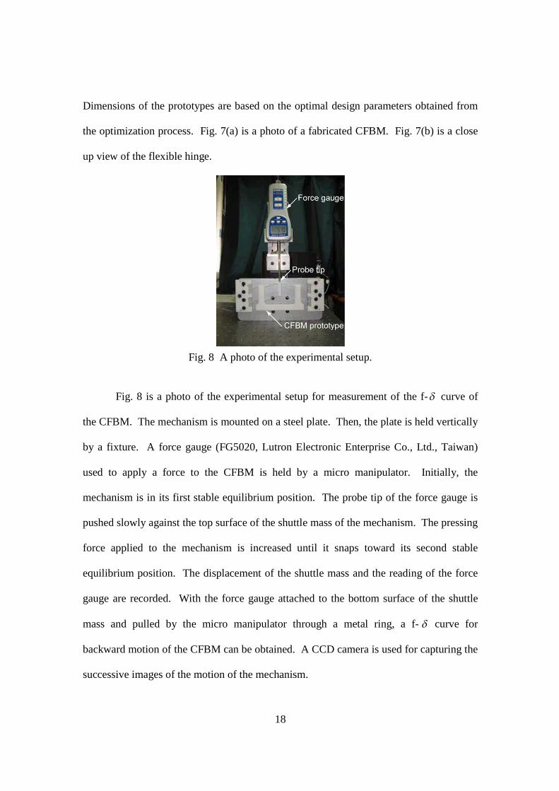
Fig. 8 A photo of the experimental setup.
Fig. 8 is a photo of the experimental setup for measurement of the f-curve of
the CFBM. The mechanism is mounted on a steel plate. Then, the plate is held vertically
by a fixture. A force gauge (FG5020, Lutron Electronic Enterprise Co., Ltd., Taiwan)
used to apply a force to the CFBM is held by a micro manipulator. Initially, the
mechanism is in its first stable equilibrium position. The probe tip of the force gauge is
pushed slowly against the top surface of the shuttle mass of the mechanism. The pressing
force applied to the mechanism is increased until it snaps toward its second stable
equilibrium position. The displacement of the shuttle mass and the reading of the force
gauge are recorded. With the force gauge attached to the bottom surface of the shuttle
mass and pulled by the micro manipulator through a metal ring, a f- curve for
backward motion of the CFBM can be obtained. A CCD camera is used for capturing the
successive images of the motion of the mechanism.
19
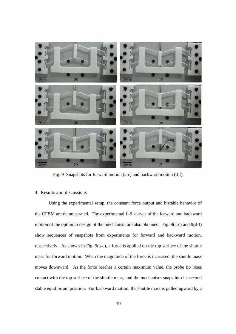
Fig. 9 Snapshots for forward motion (a-c) and backward motion (d-f).
4. Results and discussions
Using the experimental setup, the constant force output and bistable behavior of
the CFBM are demonstrated. The experimental f-curves of the forward and backward
motion of the optimum design of the mechanism are also obtained. Fig. 9(a-c) and 9(d-f)
show sequences of snapshots from experiments for forward and backward motion,
respectively. As shown in Fig. 9(a-c), a force is applied on the top surface of the shuttle
mass for forward motion. When the magnitude of the force is increased, the shuttle mass
moves downward. As the force reaches a certain maximum value, the probe tip loses
contact with the top surface of the shuttle mass, and the mechanism snaps into its second
stable equilibrium position. For backward motion, the shuttle mass is pulled upward by a
20
ring attached to the probe tip of the force gauge, and, therefore, a force is applied on the
bottom surface of the shuttle mass (see Fig. 9(d)). As the magnitude of the pulling force
reaches a certain maximum value, the ring on the probe tip loses contact with the bottom
surface of the shuttle mass, and the mechanism snaps into its first stable equilibrium
position (see Fig. 9(e,f)).
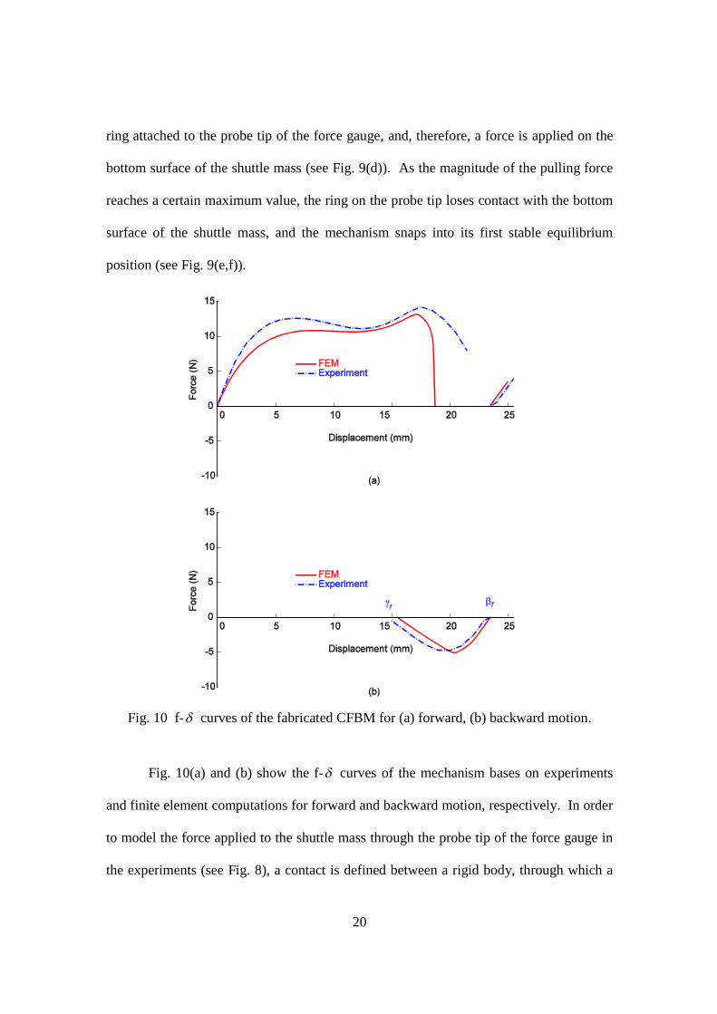
Fig. 10 f-curves of the fabricated CFBM for (a) forward, (b) backward motion.
Fig. 10(a) and (b) show the f-curves of the mechanism bases on experiments
and finite element computations for forward and backward motion, respectively. In order
to model the force applied to the shuttle mass through the probe tip of the force gauge in
the experiments (see Fig. 8), a contact is defined between a rigid body, through which a
21
force is applied, and a node of a beam element of the shuttle mass in the finite element
analyses. As shown in Fig. 10(a), a nearly constant force is observed in the operational
range from the displacement of 7.00 to 14.00 mm based on both the experiments and
finite element analyses. For forward motion, before the applied force reaches the
maximum value, the experimental results are slightly higher than those based on the finite
element analyses. As the probe tip pushes the shuttle mass further, a reduction in the
output force indicates the incoming of the snap-through of the CFBM (see Fig. 6). In the
event of snap-through, the probe tip loses contact with the shuttle mass and the
mechanism jumps to its second stable equilibrium position. For backward motion, before
the applied force reaches the maximum magnitude value, the experimental results are
slightly lower than those based on the finite element analyses. As the probe tip pushes
the shuttle mass further, a reduction in the magnitude of the output force indicates the
incoming of the snap-through of the CFBM. In the event of snap-through, the probe tip
loses contact with the shuttle mass and the mechanism jumps to its first stable
equilibrium position.
It is observed that, before the snap-through, the magnitudes of the output force
based on the experiments are greater than those of the finite element analyses. This can
be attributed to the uncertainties in geometry and loading conditions of the experiments.
The fabricated mechanism has slightly larger beam widths than the designed value due to
the manufacturing error in the milling process. The contact of the probe tip of the force
gauge with the surface of the shuttle mass is not fixed, where sliding may occur, and the
alignment of the force gauge with the symmetry plane of the CFBM may not be perfect
during the experiments, where twisting of the CFBM may happen. Also, the effects of
22
overlapping beam widths at the connecting nodes are not considered by the beam element
B21H employed in ABAQUS. As a result, the effective flexural rigidity of each beam
near the connecting nodes is underestimated in the finite element analyses.
In this investigation, the value of the constant output force is not a design variable.
It can be specified as a design constraint of the optimization procedure at the expense of
computational time. The average computational time on a personal computer with the
Intel Core 2 DuoTM processor at 2.53 and 1.67 GHz and 3.50 GB RAM for the design
case considered is around 80 hours. The preload region, the displacement range from a
to b (see Fig. 2), should be as small as possible in order to increase the operational range.
However, the sharp change in structure stiffness may cause divergence in the finite
element analyses due to the high nonlinearity of the structural response.
5. Conclusions
A CFBM has been successfully designed by an optimization procedure and
validated by experiments. Using the design methodology, a specified constant force
range can be attained without exceeding the yield stress of the material. The CFBM
consists of beams with profiles of cubic Bézier curves and cosine curves. The
combination of a chevron-type mechanism and a bistable mechanism of the CFBM
provides the constant output force for force regulation and the bistability for
impact/overloading protection. The feasibility of using the mechanism to achieve
constant output force and bistability is confirmed by finite element analyses. In order to
confirm the effectiveness of the CFBM, prototypes of the mechanism are fabricated using
a simple milling process. The force versus displacement curve of the mechanism exhibits
23
a constant output force of nearly 11 N in the specified operational range of 7.00 to 14.00
mm and a maximum output force of nearly 13 N for the bistable snap-through of the
mechanism. The presented design method of the CFBM provides a simple and efficient
means of attaining a constant output force in a specified operational range and overload
protection of the mechanism under a specified maximum load. The proposed CFBM may
be incorporated into an ultrasonic machine tool against damage caused by excessive
contact force between the tool and unknown surface conditions while maintaining a
constant force output in the operational range of the system.
Acknowledgement
The computing facilities provided by the National Center for High-Performance
Computing (NCHC) are greatly appreciated. The machining equipments provided by the
machine shop of National Chung Hsing University (NCHU) and Micro/Nano Machining
Laboratory in NCHU, R.O.C., are greatly appreciated. Helpful discussions with
Professor Chao-Chieh Lan of National Cheng Kung University, Taiwan, R.O.C. are
greatly appreciated. The authors are also thankful for the financial support from the
National Science Council, R.O.C., under Grant No. NSC 96-2221-E-005-095.
24
References
[1] J.G. Jenuwine, A. Midha, Synthesis of single-input and multiple-output port
mechanisms with springs for specified energy absorption, Journal of Mechanical
design 116 (1994) 937-943.
[2] L.L. Howell, S.P. Magleby, Substantially constant-force exercise machine, US
Patent, 7060012, 2006.
[3] J.C. Meaders, C.A. Mattson, Optimization of near-constant force springs subject to
mating uncertainty, Structural and Multidisciplinary Optimization 41 (2010) 1-15.
[4] G. Berselli, R. Vertechy, G. Vassura, P.C. Vincenzo, Design of a single-acting
constant-force actuator based on dielectric elastomers, Journal of Mechanisms and
Robotics 1 (2009) 031007.
[5] C.-C. Lan, J.-H. Wang, Y.-H. Chen, A compliant constant-force mechanism for
adaptive robot end-effector operations, Proceedings of the IEEE International
Conference on Robotics and Automation, Anchorage, Alaska, May 3-7, 2010, pp.
2131-2136.
[6] D. Bossert, U.-L. L, J. Vagners, Experimental evaluation of a hybrid position and
force surface following algorithm for unknown surfaces, Proceedings of the 1996
IEEE International Conference on Robotics and Automation, Minneapolis,
Minnesota, vol. 3, 22-28 April 1996, 2252-2257.
[7] E. A. Erlbacher, Method for applying constant force with nonlinear feedback
control and constant force device using same, US Patent, 5448146, 1995.
[8] C.B.W. Pedersen, N.A. Fleck, G.K. Ananthasuresh, Design of a compliant
mechanism to modify an actuator characteristic to deliver a constant output force,
25
Journal of Mechanical Design 128 (2006) 1101-1112.
[9] B.L. Weight, C.A. Mattson, S.P. Magleby, L.L. Howell, Configuration selection,
modeling, and preliminary testing in support of constant force electrical connectors,
ASME Journal of Electronic Packaging 129 (2007) 236-246.
[10] C.L. Boyle, L.L. Howell, S.P. Magleby, M.S. Evans, Dynamic modeling of
compliant constant-force compression mechanisms, Mechanism and Machine
Theory 38 (2003) 1468-1487.
[11] D.R. Nahar, T. Sugar, Compliant constant-force mechanism with a variable output
for micro/macro applications, Proceedings of the 2003 IEEE International
Conference on Robotics and Automation, Taipei, Taiwan, September 14-19, 2003,
pp. 318-323.
[12] L.L. Howell, Compliant Mechanisms, John Wiley & Sons, New York, 2002.
[13] Z.Y. Yu, K.P. Rajurkar, A. Tandon, Study of 3D micro-ultrasonic machining,
Journal of Manufacturing Science and Engineering 126 (2004) 727-732.
[14] D.-A. Wang, H.-T. Pham, Y.-H. Hsieh, Dynamically switching of an
electromagnetically driven compliant bistable mechanism, Sensors and Actuators A
149 (2009) 143-151.
[15] J. Qiu, J.H. Lang, A.H. Slocum, A curved-beam bistable mechanism, Journal of
Microelectromechanical Systems 13 (2004) 137-146.
[16] D.F. Rogers, J.A. Adams, Mathematical elements for computer graphics, 2nd edition,
McGRAW-Hill, New York, 1990.
[17] D. Salomon, Curves and surfaces for computer graphics, Springer, New York,
2006.
26
[18] K. Deb, A. Pratap, S. Agarwal, T. Meyarivan, A fast and elitist multiobjective
genetic algorithm: NSGA-II, IEEE Transactions on Evolutionary Computation 6
(2002) 182-197.
[19] N. Srinivas, K. Deb, Multiobjective optimization using nondominated sorting in
genetic algorithms, Journal of Evolutionary Computation 2 (1995) 221-248.
[20] H.D. Hibbitt, B.I. Karlsson., E.P. Sorensen, ABAQUS user manual, Version 6-2,
HKS Inc. Providence, RI, USA, 2001.
[21] H. Benabdallah, D. Olender, Finite element simulation of the wear of
polyoxymethylene in pin-on-disc configuration, Wear 261 (2006) 1213-1224.
27
Biographies
Huy-Tuan Pham received the B.S. degree in mechanical engineering from the Ho Chi
Minh City University of Technology, Vietnam, in 2005, and the M.S degree from the
Graduate Institute of Precision Engineering, National Chung Hsing University, Taiwan,
ROC., in 2008. He is currently working towards the Ph.D. degree in the Graduate
Institute of Precision Engineering, National Chung Hsing University, Taiwan, ROC. His
research interests are micromachined resonators and actuators, and compliant
mechanisms.
Dung-An Wang received the Ph.D. degree in mechanical engineering from the
University of Michigan at Ann Arbor, in 2004. He is currently an Associate Professor in
the Graduate Institute of Precision Engineering, National Chung Hsing University,
Taiwan, ROC. His research interests include micromachined resonators and actuators,
piezoelectric actuators, microassembly and compliant mechanisms.
28
List of figures
Fig. 1 Schematic of a CFBM and its operational principle.
Fig. 2 (a) A typical force versus displacement curve of the CFBM and the corresponding
positions at displacement a (b), displacement c (c), displacement d (d), and
displacement g (e).
Fig. 3 (a) A schematic of the upper-left branch of the CFBM. (b) Dimensions of the
guide beam and the shuttle mass.
Fig. 4 Flowchart of the optimization procedure.
Fig. 5 A mesh for the finite element model.
Fig. 6 (a) A f-curve and maximum stress versus displacement curve; (b) strain energy
curve based on a finite element model of the optimized solution.
Fig. 7 (a) A photo of a fabricated CFBM. (b) A close-up view of the flexible hinge.
Fig. 8 A photo of the experimental setup.
Fig. 9 Snapshots for forward motion (a-c) and backward motion (d-f).
Fig. 10 f-curves of the fabricated CFBM for (a) forward, (b) backward motion.