Embed Size (px)
Citation preview
A Creative Line Differential Protection Scheme forthe Hudson River Crossing Section of a 345kV
Transmission LineMike Kockott, Bharadwaj VasudevanABB Inc.
Raleigh, NC, USA
Alex Echeverria, Eric AndersonNYPA
White Plains, NY, USA
I INTRODUCTION: THE RFK-305 RELAY UPGRADEPROJECT
The line differential protection relay scheme protecting theHudson River crossing portion of the 345kV RFK-305transmission line was obsolete and parts replacement wasbecoming increasingly problematic. Additionally, along withstandard CT’s mounted in the cable crossing potheads, thisparticular design required the use of unique and expensivestep-down and impedance matching current transformers usedto supply the actual differential current signals monitored atboth East (ETS) and West Transition Stations (WTS) to therelays which were located at the WTS only. One set of themonitored current signals must transverse the river from theETS to the WTS, approximately 1.3 miles by use of smallgauge copper wire installed with the main power conductorsthus necessitating the need for impedance matchingtransformers to “boost” the strength of the current signals.These transformers were showing increased signs ofdegradation and replacements were not readily available andwould require a custom build.
The upgraded line differential protection scheme proposedby ABB was a custom designed system for upgrading the linedifferential protection and communications system betweenboth transition stations. Other relay manufacturers alsosubmitted proposed designs, but all required the continued useof the specialized current transformers. The ABB designplaced the IEDs at both transition stations thus eliminating theneed for the specialized current transformers. The existingstandard pothead CT’s at both transition stations were toremain in the design to provide the main current sensingsource for the ABB IEDs. The current signals would betransmitted between the relays by a communications pathcreated out of the same wires that originally carried the actualline current signals. Prior to selecting ABB’s design as the
final to be implemented, several scheme type alternativeswere also considered as follows:
· Installation of fiber optic cable under the river. Thischoice was found to be prohibitively expensive (approx. $3M)and also involved securing the rights to cross under two non-NYPA owned ROW’s and personal property including privatehousing.
· Installation of microwave towers and transmitter /receivers at both stations. This choice was also prohibitivelyexpensive (approx. $1M) and impractical as the only signalscrossing the river via the microwave channel would beeighteen (18) current signals, when the technology wascapable of much more. Additional non-relaying typecommunication uses for this channel could not be identified.
· Replacement of the existing relays only. This optioncould not be implemented without retaining the problematicspecialized current transformers. Two leading manufacturers,including ABB, were asked to review the design to determineif their relays could accommodate the existing current inputswithout the special transformers and all indicated that theirrelays could not operate properly without the impedancematching transformers.
· Using leased fiber optic lines from the local telephoneprovider. The success of the differential protection schemeusing a communications channel between the IEDs relies onthe quality and consistency of the transmitted current signalswhich are time stamped for direct comparison by the IEDs.The time delay (latency) and signal quality could not beguaranteed by the local telco provider.
Ultimately, the protection equipment and communicationsystem design proposed by ABB was considered the onlyviable alternative. Further, ABB was the only availablesupplier of this customized equipment and was the prime
reason why its design was selected. Other advantages to thisdesign over some others proposed included:
· Because of the ABB IED’s current sensing configurationand custom logic, only three relays would be needed at eachtransition station with each relay being able to monitor (6) sixconductors. Other designs would have required (6) six relaysat each station, each monitoring only (3) three conductors. TheABB design satisfied the prime design criterion which was theability to identify the fault location in a specific conductor ofthe (18) eighteen total conductors transiting the Hudson River.
· The existing lockout relay (LOR) design could beretained as the existing direct transfer trip (DTT) audio tonescheme was largely untouched by the design change.
· Since only (3) IEDs were required at each transitionstation, the ABB IEDs installed in the East Transition Station,an extremely small metal sided building, could fit into one,slightly shortened, standard relay panel. There was thusminimal impact to the floor layout of the East TransitionStation.
II OVERVIEW – LINE DIFFERENTIAL PROTECTION
Line differential protection applies Kirchhoff's law andcompares the currents entering and leaving the protectedcircuit. As the line-end IEDs are geographically separated,details of the measured currents must be exchanged betweenthe IEDs to perform this comparison. This exchange is madeutilizing IED to IED digital communications channel/s.
Figure 1: Example of two-terminal line differentialapplication
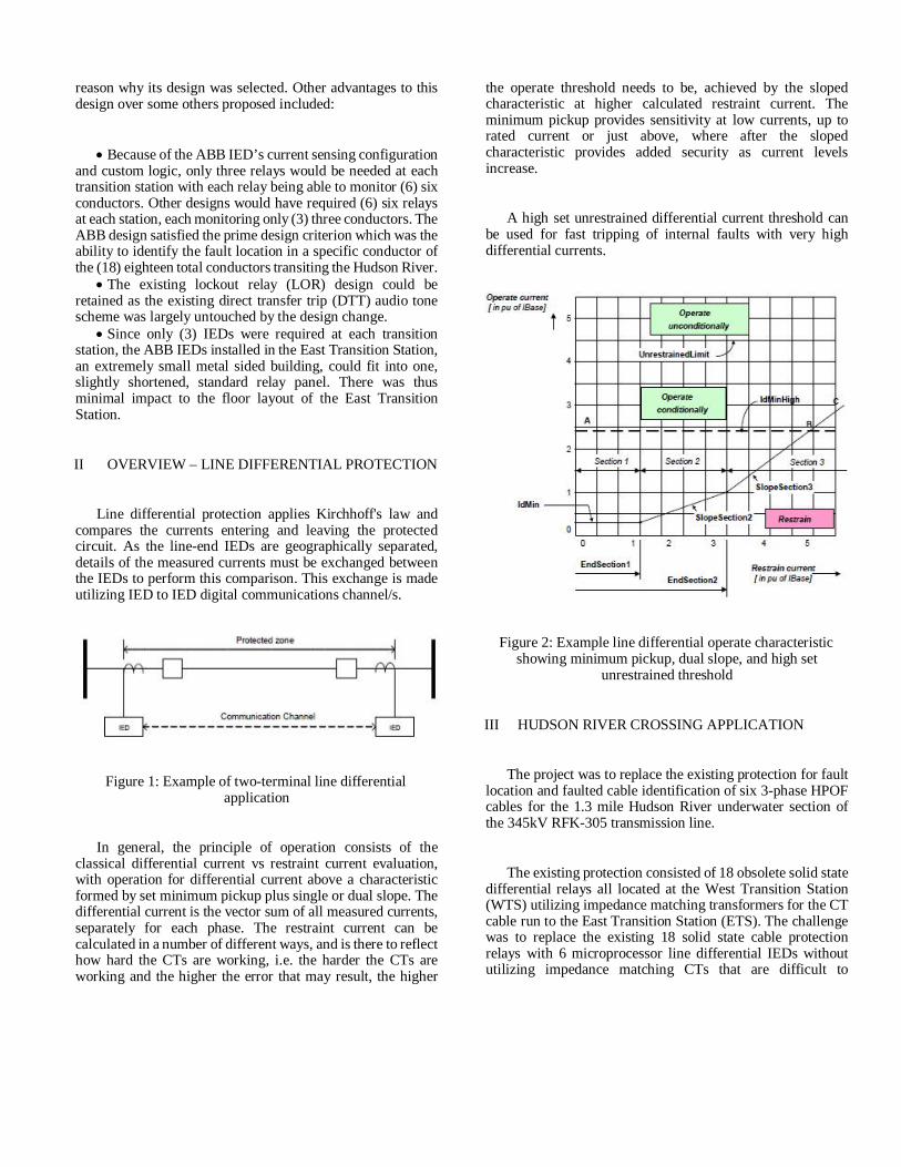
In general, the principle of operation consists of theclassical differential current vs restraint current evaluation,with operation for differential current above a characteristicformed by set minimum pickup plus single or dual slope. Thedifferential current is the vector sum of all measured currents,separately for each phase. The restraint current can becalculated in a number of different ways, and is there to reflecthow hard the CTs are working, i.e. the harder the CTs areworking and the higher the error that may result, the higher
the operate threshold needs to be, achieved by the slopedcharacteristic at higher calculated restraint current. Theminimum pickup provides sensitivity at low currents, up torated current or just above, where after the slopedcharacteristic provides added security as current levelsincrease.
A high set unrestrained differential current threshold canbe used for fast tripping of internal faults with very highdifferential currents.
Figure 2: Example line differential operate characteristicshowing minimum pickup, dual slope, and high set
unrestrained threshold
III HUDSON RIVER CROSSING APPLICATION
The project was to replace the existing protection for faultlocation and faulted cable identification of six 3-phase HPOFcables for the 1.3 mile Hudson River underwater section ofthe 345kV RFK-305 transmission line.
The existing protection consisted of 18 obsolete solid statedifferential relays all located at the West Transition Station(WTS) utilizing impedance matching transformers for the CTcable run to the East Transition Station (ETS). The challengewas to replace the existing 18 solid state cable protectionrelays with 6 microprocessor line differential IEDs withoututilizing impedance matching CTs that are difficult to
maintain, and without adding any additional communicationinterface for the protection, i.e. the IED to IED digitalcommunication needed to use the existing copper CT cablesas the communication interface.
Figure 3: RFK-305 transmission line Roseton – East Fishkillshowing under river section comprising six 3-phase HPOF
cables
The relaying solution opted for was to apply six linedifferential IEDs to provide the protection for the six cables.Therefore each pair of cables (1 and 6, 2 and 5, 3 and 4)formed a line differential zone, with one IED at the WTS endand one IED at the ETS end, in total three IEDs at WTS andthree at ETS covering the three cable pairs.
Furthermore, it was decided that the actual 87L linedifferential protection was only required at WTS as theexisting LORs to send a DTT (to Roseton to blockautoreclosing for a fault in the under-river cable portion of theline) were only at the WTS location.
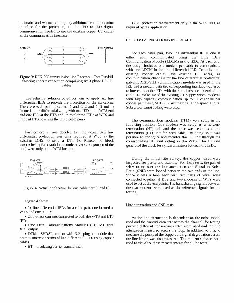
Figure 4: Actual application for one cable pair (1 and 6)
Figure 4 shows:
· 2x line differential IEDs for a cable pair, one located atWTS and one at ETS.
· 2x 3-phase currents connected to both the WTS and ETSIEDs.
· Line Data Communications Modules (LDCM), withX.21 output.
· DTM – SHDSL modem with X.21 plug-in module thatpermits interconnection of line differential IEDs using coppercables.
· BT – insulating barrier transformer.
· 87L protection measurement only in the WTS IED, asrequired by the application.
IV COMMUNICATIONS INTERFACE
For each cable pair, two line differential IEDs, one ateither end, communicated using the Line DataCommunication Module (LDCM) in the IEDs. At each end,the design included one modem per cable to communicatewith one LDCM in the line differential IED. To utilize theexisting copper cables (the existing CT wires) ascommunication channels for the line differential protection;galvanic X.21/V.11 communication module was used in theIED and a modem with the corresponding interface was usedto interconnect the IEDs with their modems at each end of thecable. To make use of the existing CT copper wires, modemswith high capacity communication up to 32 channels percopper pair using SHDSL (Symmetrical High-speed DigitalSubscriber Line) coding were used.
The communication modems (DTM) were setup in thefollowing fashion. One modem was setup as a networktermination (NT) unit and the other was setup as a linetermination (LT) unit for each cable. By doing so it waspossible to configure and monitor the LT unit through thecorresponding NT unit sitting in the WTS. The LT unitgenerated the clock for synchronization between the IEDs.
During the initial site survey, the copper wires wereinspected for purity and usability. For these tests, the pair ofwires to measure the line attenuation and Signal to NoiseRatio (SNR) were looped between the two ends of the line.Since it was a loop back test, two pairs of wires wereconnected together at ETS and two modems at WTS wereused to act as the end points. The handshaking signals betweenthe two modems were used as the reference signals for thetesting.
Line attenuation and SNR tests
As the line attenuation is dependent on the noise modelused and the transmission rate across the channel, for testingpurpose different transmission rates were used and the lineattenuation measured across the loop. In addition to this, tomeasure the purity of the copper, the signal degradation acrossthe line length was also measured. The modem software wasused to visualize these measurements for all the tests.
To give a general scale of reference for comparison ofthese values, in the copper cables, see the following for lineattenuation.
Similarly, see the following for SNR margin.
From the test results and comparing with the referenceshown above, it can be seen that the existing copper was goodenough to utilize the maximum 32 channels in a single copperpair. Since the amount of data transmitted was minimal, justthe 3 currents from each cable end and a few binary signals, itwas decided to enable only 3 channels of 64kbps per modempair in this design.
V 87L FUNCTION
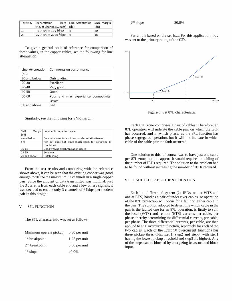
The 87L characteristic was set as follows:
Minimum operate pickup 0.30 per unit
1st breakpoint 1.25 per unit
2nd breakpoint 3.00 per unit
1st slope 40.0%
2nd slope 80.0%
Per unit is based on the set IBase. For this application, IBasewas set to the primary rating of the CTs.
Figure 5: Set 87L characteristic
Each 87L zone comprises a pair of cables. Therefore, an87L operation will indicate the cable pair on which the faulthas occurred, and in which phase, as the 87L function hasphase segregated operation, but it will not indicate in whichcable of the cable pair the fault occurred.
One solution to this, of course, was to have just one cableper 87L zone, but this approach would require a doubling ofthe number of IEDs required. The solution to the problem hadto be found without increasing the number of IEDs required.
VI FAULTED CABLE IDENTIFICATION
Each line differential system (2x IEDs, one at WTS andone at ETS) handles a pair of under river cables, so operationof the 87L protection will occur for a fault on either cable inthe pair. The solution adopted to determine which cable in thepair is the faulted one for an 87L operation, is firstly to sumthe local (WTS) and remote (ETS) currents per cable, perphase, thereby determining the differential currents, per cable,per phase. The three differential currents, per cable, are thenapplied to a 50 overcurrent function, separately for each of thetwo cables. Each of the IDiff 50 overcurrent functions hasthree pickup thresholds, step1, step2 and step3, with step1having the lowest pickup threshold and step3 the highest. Anyof the steps can be blocked by energizing its associated blockinput.
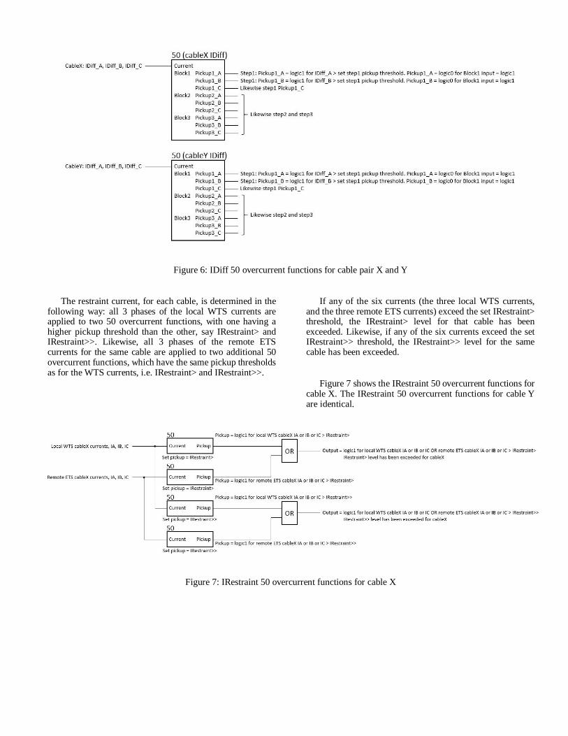
Figure 6: IDiff 50 overcurrent functions for cable pair X and Y
The restraint current, for each cable, is determined in thefollowing way: all 3 phases of the local WTS currents areapplied to two 50 overcurrent functions, with one having ahigher pickup threshold than the other, say IRestraint> andIRestraint>>. Likewise, all 3 phases of the remote ETScurrents for the same cable are applied to two additional 50overcurrent functions, which have the same pickup thresholdsas for the WTS currents, i.e. IRestraint> and IRestraint>>.
If any of the six currents (the three local WTS currents,and the three remote ETS currents) exceed the set IRestraint>threshold, the IRestraint> level for that cable has beenexceeded. Likewise, if any of the six currents exceed the setIRestraint>> threshold, the IRestraint>> level for the samecable has been exceeded.
Figure 7 shows the IRestraint 50 overcurrent functions forcable X. The IRestraint 50 overcurrent functions for cable Yare identical.
Figure 7: IRestraint 50 overcurrent functions for cable X
If no IRestraint level has been exceeded, no blocking ofthe IDiff 50 overcurrent function occurs. If the IRestraint>level has been exceeded, block step1 of the IDiff 50overcurrent function. Similarly, if the IRestraint>> level hasbeen exceeded, block step2 of the IDiff 50 overcurrentfunction. If the IRestraint>> level has been exceeded,
IRestraint> level would also have been exceeded, so forIRestraint>> level exceeded, step1 and step2 would beblocked. In this way, the IDiff 50 overcurrent function’spickup threshold is effectively increased for increasingmagnitude of restraint current.
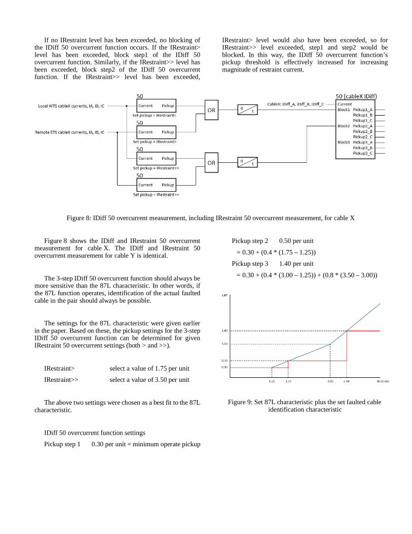
Figure 8: IDiff 50 overcurrent measurement, including IRestraint 50 overcurrent measurement, for cable X
Figure 8 shows the IDiff and IRestraint 50 overcurrentmeasurement for cable X. The IDiff and IRestraint 50overcurrent measurement for cable Y is identical.
The 3-step IDiff 50 overcurrent function should always bemore sensitive than the 87L characteristic. In other words, ifthe 87L function operates, identification of the actual faultedcable in the pair should always be possible.
The settings for the 87L characteristic were given earlierin the paper. Based on these, the pickup settings for the 3-stepIDiff 50 overcurrent function can be determined for givenIRestraint 50 overcurrent settings (both > and >>).
IRestraint> select a value of 1.75 per unit
IRestraint>> select a value of 3.50 per unit
The above two settings were chosen as a best fit to the 87Lcharacteristic.
IDiff 50 overcurrent function settings
Pickup step 1 0.30 per unit = minimum operate pickup
Pickup step 2 0.50 per unit
= 0.30 + (0.4 * (1.75 – 1.25))
Pickup step 3 1.40 per unit
= 0.30 + (0.4 * (3.00 – 1.25)) + (0.8 * (3.50 – 3.00))
Figure 9: Set 87L characteristic plus the set faulted cableidentification characteristic
Example
As an example, let’s take the 87L zone for cable pair 1 and6. Please note that in the actual engineering, the term ‘pipe’was used rather than ‘cable’, as the three phases of each‘cable’ were contained within a ‘pipe’. From now on, the term‘pipe’ will be used instead of ‘cable’.
The four current sets (where one current set = all threephases of current) connected to the 87L zone are local WTSpipe 1, local WTS pipe 6, remote ETS pipe 1 and remote ETSpipe 6.
To identify the faulted pipe in the pipe pair, the current setslocal WTS pipe 1 and remote ETS pipe 1 are summed.Similarly for pipe 6. As a security measure, the output of thissumming is blocked until there is a pickup of the 87L function,indicating that an internal fault has occurred on the pipe pair.The releasing of this summing in this way is quite OK aswithout a fault occurring on the pipe pair, no subsequentidentification of actual faulted pipe is required.
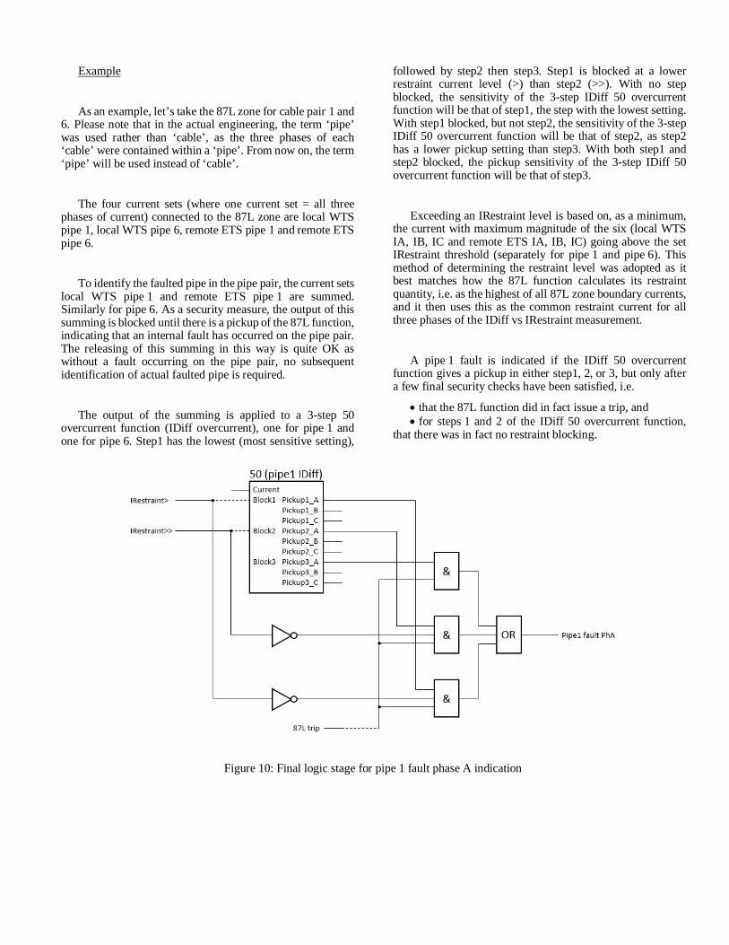
The output of the summing is applied to a 3-step 50overcurrent function (IDiff overcurrent), one for pipe 1 andone for pipe 6. Step1 has the lowest (most sensitive setting),
followed by step2 then step3. Step1 is blocked at a lowerrestraint current level (>) than step2 (>>). With no stepblocked, the sensitivity of the 3-step IDiff 50 overcurrentfunction will be that of step1, the step with the lowest setting.With step1 blocked, but not step2, the sensitivity of the 3-stepIDiff 50 overcurrent function will be that of step2, as step2has a lower pickup setting than step3. With both step1 andstep2 blocked, the pickup sensitivity of the 3-step IDiff 50overcurrent function will be that of step3.
Exceeding an IRestraint level is based on, as a minimum,the current with maximum magnitude of the six (local WTSIA, IB, IC and remote ETS IA, IB, IC) going above the setIRestraint threshold (separately for pipe 1 and pipe 6). Thismethod of determining the restraint level was adopted as itbest matches how the 87L function calculates its restraintquantity, i.e. as the highest of all 87L zone boundary currents,and it then uses this as the common restraint current for allthree phases of the IDiff vs IRestraint measurement.
A pipe 1 fault is indicated if the IDiff 50 overcurrentfunction gives a pickup in either step1, 2, or 3, but only aftera few final security checks have been satisfied, i.e.
· that the 87L function did in fact issue a trip, and· for steps 1 and 2 of the IDiff 50 overcurrent function,
that there was in fact no restraint blocking.
Figure 10: Final logic stage for pipe 1 fault phase A indication
Not shown in Figure 10, but identical, is the final stagelogic for pipe 1 phases B and C, and pipe 6 phases A, B andC.
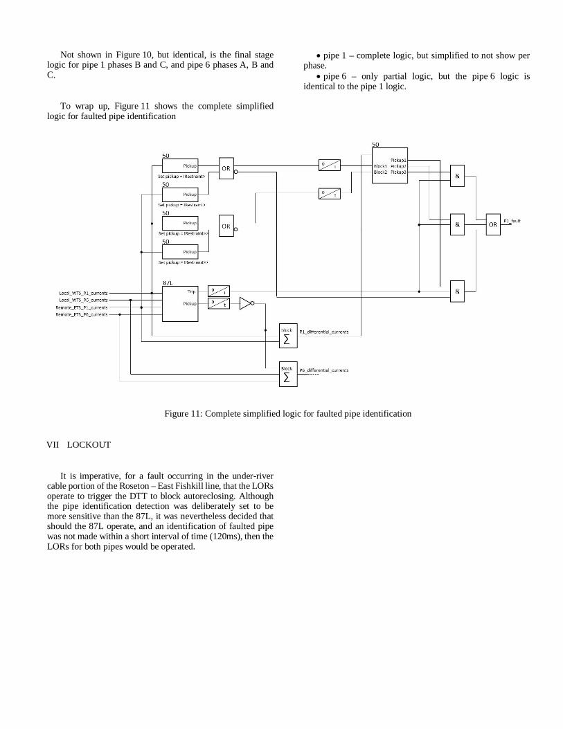
To wrap up, Figure 11 shows the complete simplifiedlogic for faulted pipe identification
· pipe 1 – complete logic, but simplified to not show perphase.
· pipe 6 – only partial logic, but the pipe 6 logic isidentical to the pipe 1 logic.
Figure 11: Complete simplified logic for faulted pipe identification
VII LOCKOUT
It is imperative, for a fault occurring in the under-rivercable portion of the Roseton – East Fishkill line, that the LORsoperate to trigger the DTT to block autoreclosing. Althoughthe pipe identification detection was deliberately set to bemore sensitive than the 87L, it was nevertheless decided thatshould the 87L operate, and an identification of faulted pipewas not made within a short interval of time (120ms), then theLORs for both pipes would be operated.
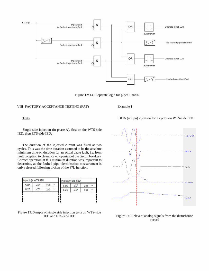
Figure 12: LOR operate logic for pipes 1 and 6
VIII FACTORY ACCEPTANCE TESTING (FAT)
Tests
Single side injection (in phase A), first on the WTS-sideIED, then ETS-side IED:
The duration of the injected current was fixed at twocycles. This was the time duration assumed to be the absoluteminimum time-on duration for an actual cable fault, i.e. fromfault inception to clearance on opening of the circuit breakers.Correct operation at this minimum duration was important todetermine, as the faulted pipe identification measurement isonly released following pickup of the 87L function.
Figure 13: Sample of single side injection tests on WTS-sideIED and ETS-side IED
Example 1
5.00A (= 1 pu) injection for 2 cycles on WTS-side IED.
Figure 14: Relevant analog signals from the disturbancerecord

‘Loc_WTS_P1_IA’ is the injected current. ‘IDiff_P1_IA’is the current connected to the IDiff 50 overcurrent functionfor pipe 1. ‘IDiff_P1_IA’ is the output from the summing ofWTS IA plus ETS IA (in this example ETS IA = 0). Theoutput from the summing is only released following pickup ofthe 87L function.
Steps 1, 2, 3 of the IDiff 50 overcurrent function are set,respectively, at 0.3, 0.5 and 1.4 pu. The first restraint levelIRestraint> is set at 1.75 pu. Therefore no steps of the IDiff 50overcurrent function should be blocked, and based on theinjected current, steps 1 and 2 of the IDiff 50 overcurrentshould operate.
Figure 15: Relevant binary signals from the disturbance record
· Correct 87L pickup and trip in phase A – pickup of‘87L PU A’ and ‘87L Trip A’ signals
· Correct identification of pipe 1 fault in phase A – pickupof ‘Pipe1 Flt A’ signal
· Correct no IRestraint> (IB>) or IRestraint>> (IB>>)level exceeded – no dropout in ‘En P1 No IB>’ and‘En P1 No IB>>’ signals
· Correct pipe 1 IDiff 50 overcurrent pickup in phase A insteps 1 and 2 – pickup of ‘P1 PU St1 A’, ‘P1 Flt St1 A’,‘P1 PU St2 A’ and ‘P1 Flt St2 A’ signals
· Correct output to operate pipe 1 LOR – pickup of‘LOR P1 OutPul’ signal
Example 2
15.00A (= 3 pu) injection for 2 cycles on WTS-side IED
The second restraint level IRestraint>> is set at 3.50 pu.This level will not be exceeded, but the first level IRestraint>will be, blocking step 1 of the IDiff 50 overcurrent. Steps 2and 3 of the IDiff 50 overcurrent function will not be blocked,and based on the injected current, steps 2 and 3 should bothoperate.
Figure 16: Relevant analog signals from the disturbancerecord
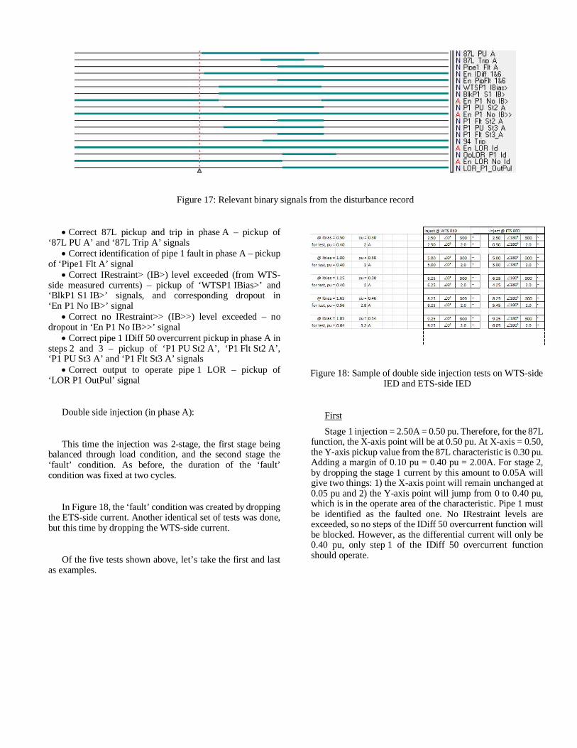
Figure 17: Relevant binary signals from the disturbance record
· Correct 87L pickup and trip in phase A – pickup of‘87L PU A’ and ‘87L Trip A’ signals
· Correct identification of pipe 1 fault in phase A – pickupof ‘Pipe1 Flt A’ signal
· Correct IRestraint> (IB>) level exceeded (from WTS-side measured currents) – pickup of ‘WTSP1 IBias>’ and‘BlkP1 S1 IB>’ signals, and corresponding dropout in‘En P1 No IB>’ signal
· Correct no IRestraint>> (IB>>) level exceeded – nodropout in ‘En P1 No IB>>’ signal
· Correct pipe 1 IDiff 50 overcurrent pickup in phase A insteps 2 and 3 – pickup of ‘P1 PU St2 A’, ‘P1 Flt St2 A’,‘P1 PU St3 A’ and ‘P1 Flt St3 A’ signals
· Correct output to operate pipe 1 LOR – pickup of‘LOR P1 OutPul’ signal
Double side injection (in phase A):
This time the injection was 2-stage, the first stage beingbalanced through load condition, and the second stage the‘fault’ condition. As before, the duration of the ‘fault’condition was fixed at two cycles.
In Figure 18, the ‘fault’ condition was created by droppingthe ETS-side current. Another identical set of tests was done,but this time by dropping the WTS-side current.
Of the five tests shown above, let’s take the first and lastas examples.
Figure 18: Sample of double side injection tests on WTS-sideIED and ETS-side IED
First
Stage 1 injection = 2.50A = 0.50 pu. Therefore, for the 87Lfunction, the X-axis point will be at 0.50 pu. At X-axis = 0.50,the Y-axis pickup value from the 87L characteristic is 0.30 pu.Adding a margin of 0.10 pu = 0.40 pu = 2.00A. For stage 2,by dropping the stage 1 current by this amount to 0.05A willgive two things: 1) the X-axis point will remain unchanged at0.05 pu and 2) the Y-axis point will jump from 0 to 0.40 pu,which is in the operate area of the characteristic. Pipe 1 mustbe identified as the faulted one. No IRestraint levels areexceeded, so no steps of the IDiff 50 overcurrent function willbe blocked. However, as the differential current will only be0.40 pu, only step 1 of the IDiff 50 overcurrent functionshould operate.
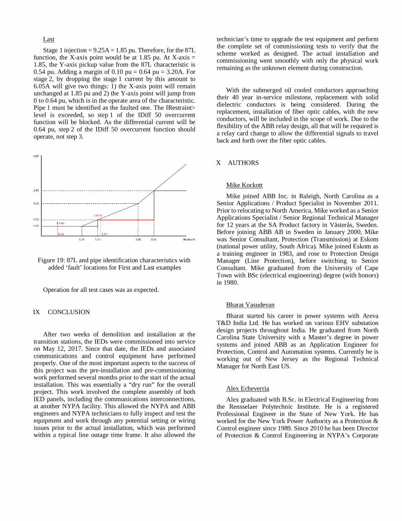
Last
Stage 1 injection = 9.25A = 1.85 pu. Therefore, for the 87Lfunction, the X-axis point would be at 1.85 pu. At X-axis =1.85, the Y-axis pickup value from the 87L characteristic is0.54 pu. Adding a margin of 0.10 pu = 0.64 pu = 3.20A. Forstage 2, by dropping the stage 1 current by this amount to6.05A will give two things: 1) the X-axis point will remainunchanged at 1.85 pu and 2) the Y-axis point will jump from0 to 0.64 pu, which is in the operate area of the characteristic.Pipe 1 must be identified as the faulted one. The IRestraint>level is exceeded, so step 1 of the IDiff 50 overcurrentfunction will be blocked. As the differential current will be0.64 pu, step 2 of the IDiff 50 overcurrent function shouldoperate, not step 3.
Figure 19: 87L and pipe identification characteristics withadded ‘fault’ locations for First and Last examples
Operation for all test cases was as expected.
IX CONCLUSION
After two weeks of demolition and installation at thetransition stations, the IEDs were commissioned into serviceon May 12, 2017. Since that date, the IEDs and associatedcommunications and control equipment have performedproperly. One of the most important aspects to the success ofthis project was the pre-installation and pre-commissioningwork performed several months prior to the start of the actualinstallation. This was essentially a “dry run” for the overallproject. This work involved the complete assembly of bothIED panels, including the communications interconnections,at another NYPA facility. This allowed the NYPA and ABBengineers and NYPA technicians to fully inspect and test theequipment and work through any potential setting or wiringissues prior to the actual installation, which was performedwithin a typical line outage time frame. It also allowed the
technician’s time to upgrade the test equipment and performthe complete set of commissioning tests to verify that thescheme worked as designed. The actual installation andcommissioning went smoothly with only the physical workremaining as the unknown element during construction.
With the submerged oil cooled conductors approachingtheir 40 year in-service milestone, replacement with soliddielectric conductors is being considered. During thereplacement, installation of fiber optic cables, with the newconductors, will be included in the scope of work. Due to theflexibility of the ABB relay design, all that will be required isa relay card change to allow the differential signals to travelback and forth over the fiber optic cables.
X AUTHORS
Mike Kockott
Mike joined ABB Inc. in Raleigh, North Carolina as aSenior Applications / Product Specialist in November 2011.Prior to relocating to North America, Mike worked as a SeniorApplications Specialist / Senior Regional Technical Managerfor 12 years at the SA Product factory in Västerås, Sweden.Before joining ABB AB in Sweden in January 2000, Mikewas Senior Consultant, Protection (Transmission) at Eskom(national power utility, South Africa). Mike joined Eskom asa training engineer in 1983, and rose to Protection DesignManager (Line Protection), before switching to SeniorConsultant. Mike graduated from the University of CapeTown with BSc (electrical engineering) degree (with honors)in 1980.
Bharat Vasudevan
Bharat started his career in power systems with ArevaT&D India Ltd. He has worked on various EHV substationdesign projects throughout India. He graduated from NorthCarolina State University with a Master’s degree in powersystems and joined ABB as an Application Engineer forProtection, Control and Automation systems. Currently he isworking out of New Jersey as the Regional TechnicalManager for North East US.
Alex Echeverria
Alex graduated with B.Sc. in Electrical Engineering fromthe Rensselaer Polytechnic Institute. He is a registeredProfessional Engineer in the State of New York. He hasworked for the New York Power Authority as a Protection &Control engineer since 1989. Since 2010 he has been Directorof Protection & Control Engineering in NYPA’s Corporate
Headquarters. He serves as the design authority for all ofNYPA’s protection systems for generation, substation andtransmission systems and performs generation andtransmission system disturbance analysis for all NYPA relayoperations. He is the Chairman on the Task Force for SystemProtection for the Northeast Power Coordinating Council. Heis a member of the North American Electric ReliabilityCorporation’s System Protection & Control Subcommitteewhere he is the Subject Matter Expert for all NERC Standards.
Eric Anderson
Eric currently works for the New York Power Authority,headquartered in White Plains, New York. He is assigned tothe Engineering Department of the Operations Support
Business Unit working with the Protection and ControlEngineering Group with the title of Senior Protection andControl Engineer. Eric has forty-two years of experience inthe power plant engineering and design field with a majorityof the experience in the engineering and design of nuclearpower plant electrical and auxiliary systems. Eric is a graduateof the State University of New York Maritime College at FortSchuyler, Bronx, New York. He graduated in 1976 with aBachelor of Engineering Degree in Marine Engineering -Electrical Concentration. He is a licensed ProfessionalEngineer in the State of New York. Eric is a member of theInstitute of Electrical and Electronic Engineers and the PowerEngineering Society. He is a member of NPCC’s Task Forceon System Protection SP-7 Working Group on BES / BPSRelay Misoperations and a member of the NYISO SystemProtection Advisory Subcommittee.