Embed Size (px)
Citation preview

Bachelor’s Thesis Degree Program in Information Technology 2010 Ding Yi
A Data Conversion Program for
μShape™ Binary File

II
BACHELOR’S THESIS | ABSTRACT
TURKU UNIVERSITY OF APPLIED SCIENCES
Information Technology
Spring 2010 | 50
Instructor: Patric Granholm
Ding Yi
A Data Conversion Program for μShape™ Binary
File The work of data conversion hidden beneath the sophisticated computer world happens more
often than people can ever imagine. File data is one of the most primary elements that have
been “shaped” in different ways in order to fulfill a particular file purpose. If some of the data
structures are obsolete or a file function needs to be altered, data conversion is taking place.
In this thesis conversion from μShape software which generates a file specific format “*.fis” to
standard uncompressed bitmap file format “*.bmp” is implemented. The empirical part of
conversion was conducted on a C language program c which was separated into two individual
sub-programs. The first program was used to read in a fis file generated by μShape and write out
a standard bitmap file. In this program, the deviation data as well as metrology needed to
concrete the bitmap later can be obtained from file header information of FIS file. The second
program inherits the successful achievement of first objective and arranges and modifies all the
file data into a scaled color map. This is the key step to make the output of bitmap file optical
observation possible, since the generated color in this case is the measurement of the surface
deviation of the image.
Although the encoded way of data may vary considerably from file to file, the aim of the project is
to attempt explore the conversion technique as well as to give general guidelines especially
when it comes to secret specifications of a file format.
KEYWORDS:
data conversion, bitmap, BMP, FIS, RGB model, format conversion, surface deviation

III
Contents Notation ........................................................................................................................................ V
Figures Figure 1.Typical uncompressed bitmap image and its magnified view ………………….5 Figure 2.Spectral response curves for each cone cell. The peak points for each curve are at 450nm (blue), 530nm (green) and 630nm (red). ...................................................... 10
Figure 3.The RGB color model, defining colors with an additive process within the unit cube. ........................................................................................................................................... 11
Figure 4.The typical view of the RGB color cube, along the grayscale diagonal from white to black. ........................................................................................................................... 12
Figure 5.The workspace window of μShape 6.0 ................................................................. 13
Figure 6.BMP image converted from the file with no RGB model applied ...................... 24
Figure 7.The conversion BMP image from the FIS file with RGB color rendering ......... 31
Tables Table 1.The four hierarchical layers of the BMP file ............................................................. 6
Table 2.Line padding codes in outputting a BMPfile ............................................................ 9
Table 3.Specification of FIS file header ................................................................................ 14
Table 4.The range of actual FIS data after heading, decimal values are in Angstrom . 17
Table 5.Structure of FIS header in codes ............................................................................. 17
Table 6.The actual pixel sequence of red, green and blue in the BMP file. .................... 18
Table 7.Structures of BMP files header and info header in codes. .................................. 19
Table 8.RGB bit define and bus switch ................................................................................. 20
Table 9.The highest bit from the FIS file has been removed in order to meet the pixel structure of BMP file. ............................................................................................................... 22
Table 10.The conversion code from FIS pixel to BMP pixel .............................................. 23
Table 11.Decimal values of RGB color with additive tendency ......................................... 25
Table 12.The codes demonstrate how to get polar values from a binary file ................. 26
Table 13.The function shows how to acquire scale factor for the FIS file ....................... 27
Table 14.The functions illustrate how to shift all the data to 0-1279 ................................ 28

IV
Table 15.This function depicts RGB color rendering for each pixel from converted FIS data ............................................................................................................................................. 29
1 Introduction .............................................................................................................................. 1
1.1 Data Conversion Background ........................................................................................ 1
1.2 Lossy Data Conversion ................................................................................................... 2
1.3 Methodology ..................................................................................................................... 2
2. Bitmap File .............................................................................................................................. 4
2.1 Introduction ....................................................................................................................... 4
_Toc2642538472.2 Bitmap Storage ............................................................................................ 5
2.3 BMP File Structures ........................................................................................................ 5
2.4 Color Depth Field ............................................................................................................. 7
2.5 Line Padding..................................................................................................................... 8
2.6 RGB Color Model ............................................................................................................. 9
3. FIS file .................................................................................................................................... 13
3.1 Introduction ..................................................................................................................... 13
3.2 FIS file structures ........................................................................................................... 14
4. The Conversion .................................................................................................................... 16
4.1 Tools of Conversion ...................................................................................................... 16
4.2 Pre RGB module conversion ....................................................................................... 16
4.2.1 Reading Data from FIS file.................................................................................... 17
4.2.2 Writing Data to the BMP File ................................................................................ 18
4.3 RGB Model Conversion ................................................................................................ 25
4.3.1 Peak to Valley Value .............................................................................................. 25
4.3.2 Scale Factor ............................................................................................................ 27
4.3.3 RGB Color Rendering ............................................................................................ 29
5. Summary ............................................................................................................................... 32
References ................................................................................................................................ 33
Appendix A: Table of BMP File Content ............................................................................... 35
Appendix B: Conversion Codes between Hexadecimal Value and Decimal Value ....... 38

V
Notation
BMP bitmap file format
FIS μshape file format
P-V peak to valley
SF scale factor
DIB device independent bitmap
GDI graphics device interface
PNG portable network graphics
GIF Graphic interchange format
MSDN Microsoft developer network
Angstrom 0.1 nanometer
MTF modulation transfer function
RGB model red, green, blue model

1
1 Introduction
1.1 Data Conversion Background Data conversion is the process of translating data from one format to another; it
can be converted either from human-readable to machine-readable form or vice
versa [1]. Due to the fact that the computer industry has been developed in
complicated layers and dynamic process, data is also constructed in various
formats to meet different standards. Therefore, data must be converted when it
is needed. For example, for any enterprises the annual increment of data in a
database will unveil the limitation of data construction from old software and the
entire update of certain software will definitely lead to the entire update to its
database. Because the storage of data in background database differs from
software to software, consequently when an update occurs, data conversion is a
necessity to be included. Sometimes the data conversion takes place even
because the graphical user interface of software is in a transformation.
The alteration between operating systems also takes data conversion into
account. Different operating systems have their own file system to handle data,
and for the purpose of common files sharing, data has to be converted. Another
example would be the massive data residing in hardware, even a tiny
modification of certain components of the hardware will cause the occurrence of
data conversion. Moreover, for software and web-based application the stylish
improvement of interface or add-on of new features is implemented by data
conversion. Data conversion could be carried out either in a complicated fashion
or as simple as the editing of a few bits, depending on the data types.
Logistically speaking, for instance, the conversion of data from a video clip is far
more time-consuming than that of a text file.

2
The process of data conversion can be approached through different channels.
Generally when it occurs with the upgrading of hardware, the data is usually
converted automatically in the background, for example a hardware driver will
execute the conversion when it is needed. In some other cases, certain software
has the function to open a file with a variety of formats, for instance a digital
image reader is able to open a number of different image file formats and save
them as other desired image formats, and, that is to say, it can complete the
inner data conversion without using any third party converting tools. In addition,
although it is seldom to be practiced, for the maximum freedom of
interoperability among different file formats, one can also always achieve the
data conversion by writing his/her own sophisticated program.
1.2 Lossy Data Conversion
For perfect data conversion, all of the source data and its embedded information
should be transferred into the target file. However, this can only be done if the
target format does support the same features and same data structures present
in the source file. [2] Conversion from a BMP image file to a JPEG image file
involves loss of precision of image, because the JPEG format supports
compressed images hence running a dissimilar data structure to that of the BMP
format. After the conversion is completed, the difference of two image outputs
can hardly be distinguished by human vision. The conversion, however, could
cause unexpected confusion and malfunction.
1.3 Methodology
The lack of specification and information referring to either source format or
target format is a major difficulty in data conversion, therefore reverse
engineering is then necessary to be introduced. “Reverse engineering is the

3
process of analyzing a subject system to create representations of the system at
a higher level of abstraction.”[3] It can also be seen as “going backwards through
the development cycle”. [4] Reverse engineering is re-building unknown
specifications very closely to the original file. But the progress of research is
based upon hypothesis and analysis, which the whole conversion will not be a
copy work. Instead, some unpredictable errors or uncompleted constructions or
missing features will be generated and remaining in tolerant level.
To be specific about the conversion program in this project, the secret
specifications of source file makes the programmer reverse-engineered
throughout the conversion process.

4
2. Bitmap File
2.1 Introduction
The bitmap standard file is one of the digital image storage formats widely used
on Microsoft Windows and other OS/2 systems. The file extension for a bitmap
file is “.BMP”. The bitmap image structure could be reflected plainly from its
name: a collection of bits that form an image. Note the linguistic ambiguous use
of pixmap which should not be mixed up with bitmap. “Strictly speaking, the term
bitmap applies only to 1-bit-per-pixel bilevel systems; for multiple-bit-per-pixel
systems, we use the more general term pixmap (short for pixel map).” [5] Prior to
Windows 3.0, the bitmap file was device-dependent. However, Microsoft decided
to adopt the bitmap alteration as Device-Independent Bitmap (DIB) after the
release of Windows 3.0 in order to make the bitmap file compatible with display
devices of any kind in the market at the time. Usually, bitmap files are
uncompressed images and the size of them is rather large, which causes
intensive occupation of the memory. As a result, its Web application tends to use
more light weight image formats, such as JPEG, PNG, and GIF due to the fact
lossy compression is allowed in those formats. The main disadvantage of bitmap
files is that they are not supported by Web browsers or Web-based languages.
[6] In the Microsoft scheme, it has been designed as one of the GDI objects.

5
Figure 1.Typical uncompressed bitmap image and its magnified view
2.2 Bitmap Storage
As it mentioned before, the bitmap consists of a map of bits that is stored
vertically as well as horizontally in the matrix with their individual color. For each
of the bitmap files, the image pixels are stored with a number of bits per pixel
(bpp) called color depth. Color depth is associated with the color of a single pixel
thus the more bits per pixel, the more colors will be available to produce. The
disk storage size of a standard bitmap file can be calculated by the formula as
following:
Fizesize kBN M B8 1024
Where N is the number of rows, M is the number of columns, B is the color
depth.
2.3 BMP File Structures
In general, each bitmap file is divided into either three or four parts, a bitmap file
6
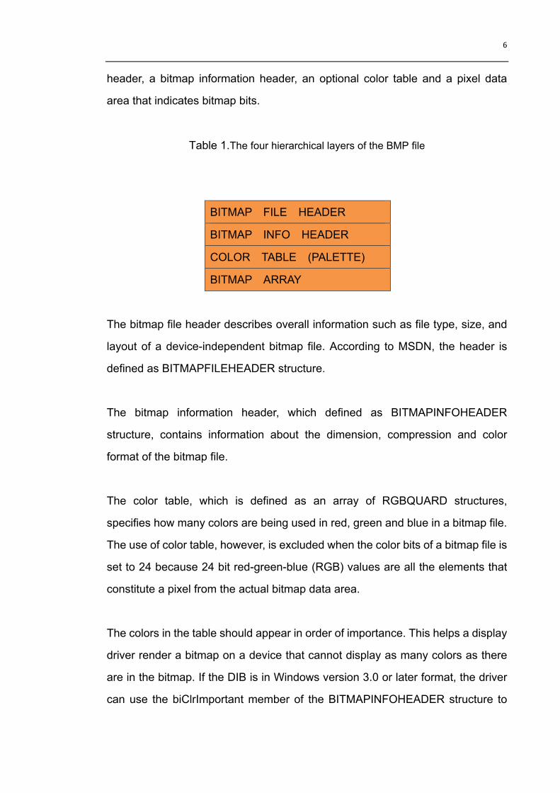
header, a bitmap information header, an optional color table and a pixel data
area that indicates bitmap bits.
Table 1.The four hierarchical layers of the BMP file
BITMAP FILE HEADER
BITMAP INFO HEADER
COLOR TABLE (PALETTE)
BITMAP ARRAY
The bitmap file header describes overall information such as file type, size, and
layout of a device-independent bitmap file. According to MSDN, the header is
defined as BITMAPFILEHEADER structure.
The bitmap information header, which defined as BITMAPINFOHEADER
structure, contains information about the dimension, compression and color
format of the bitmap file.
The color table, which is defined as an array of RGBQUARD structures,
specifies how many colors are being used in red, green and blue in a bitmap file.
The use of color table, however, is excluded when the color bits of a bitmap file is
set to 24 because 24 bit red-green-blue (RGB) values are all the elements that
constitute a pixel from the actual bitmap data area.
The colors in the table should appear in order of importance. This helps a display
driver render a bitmap on a device that cannot display as many colors as there
are in the bitmap. If the DIB is in Windows version 3.0 or later format, the driver
can use the biClrImportant member of the BITMAPINFOHEADER structure to

7
determine which colors are important. [7]
The storage order of pixels in the data area is considered to be upside-down,
arranging from left to right, ascending row by row with a starting point at the
lower left corner all the way to the upper right corner.
Note: The BMP file content can be obtained from Appendix A.
2.4 Color Depth Field
In the bits per pixel field from the BITMAPINFOHEADER structure, the actual
intensities of color and pixel existing in a bitmap are able to be set by the number
of bits. There are 6 different levels that the bit can be assigned to:
1. When the field is set to 1, the bitmap is monochrome. Only two values are
allowed in the palette, each bit in the bitmap data builds a pixel. The color of
the first value in the palette is assigned to the pixel when the bit is clear,
whereas the color of the second value will be applied to the pixel when the
bit is set.
2. When the field is set to 4, each pixel in the bitmap is represented by a 4-bit
index into the palette. No more than 16 values are allowed in the palette,
meaning that a bitmap has a maximum of 16 colors. For example, if the first
byte in the bitmap is 0x1F, the byte is equal to 2 pixels. The first pixel
contains the color in the second value of palette, and the second pixel
contains the color in the sixteenth palette.
3. When the field is set to 8, the bitmap can have a maximum capacity of 256
colors, and the palette contains up to 256 values. At this point, each byte in
the palette data area corresponds to one pixel.

8
4. When the field is set to 16, the bitmap can have a maximum capacity of 216
colors. In this case, the palette field remains empty only if the compression
field of the bitmap file is set to bi_rgb. Each pixel in 16 bit palette is built up
by a unit of 4 bytes value. Five bits can depict a color from red, green or blue.
The value for blue is in the least significant five bits, followed by five bits
each for green and red, respectively. The most significant bit is not used. [8]
5. When the field is set to 24, the bitmap has a maximum capacity of 224 colors,
and no entries will be set in the palette filed. A single pixel in this case
consists of 8 bytes in the bitmap data area where 3 bytes out of 8 represent
respectively a color of blue, green, and red.
6. When the field is set to 32, the bitmap has a maximum capacity of 232 colors.
If the compression field of the bitmap is set to bi_rgb, then no values in the
palette are filed. At this point, each 4 bytes represent one of the colors of
blue, green, and red. The highest byte in each pixel is not used. If the
compression field of the bitmap is set to bi_bitfields, the palette field contains
three 4 bytes color masks that specify the red, green, and blue components,
respectively, of each pixel. [8]
2.5 Line Padding
Regarding to the actual data creating, a bitmap file has an extra critical fact that
needs to be taken into account. The data of each line has to be ended on a
4-byte boundary, if the data cannot make an even 4-byte boundary at the end of
each line, then it has to be followed by redundant data. The official name of
those redundant data is “padding” and they are all zeros. For example, if the
output bitmap file from this conversion program has the dimension of 1022 ×
1022, then two zeros will be padded into the end of each data line.

9
An example can be seen from Table 2:
Table 2.Line padding codes in outputting a BMP file
DataSizePerLine=fHeader->nCol*3;
int npad = 0;
while(DataSizePerLine%4!=0) /*the pixel each line has to be the multiple of 4*/
{
DataSizePerLine++;
npad++;
}
Note: In order to load feasible bitmap file data, the line padding has to be
manually removed from each data line.
2.6 RGB Color Model
“...the Rays to speak properly are not coloured. In them there is nothing else
than a certain Power and Disposition to stir up a Sensation of this or that
Colour.”- Isaac Newton [9].
According to the tristimulus theory, the human retina has three kinds of cone
cells, which can perceive color through the peak sensitivity at wavelengths of
about 630 nm (red), 530 nm (green) and 450 nm (blue) [10]. See Figure 2. The
natural color system is far simpler than what we actually see; the capability of
comparing intensities in a light source makes us have a colorful vision. In other
words, “the perception of color is an entirely arbitrary creation of our nervous
system, and is in no way contained in the wavelengths themselves”. [11]

10
Figure 2.Spectral response curves for each cone cell. The peak points for each curve
are at 450nm (blue), 530nm (green) and 630nm (red).
In computer graphics, this theory has been widely applied to display as well as
manipulate a digital image by using three colors of red, green, and blue, usually
referred to as the RGB color model.
The RGB model could be simulated with the unit cube defined on R, G, and B
axes, as shown in Figure 3.

11
Grayscale G Green (0, 1, 0) Yellow (1, 1, 0)
White (1, 1, 1)
Cyan (0, 1, 1)
R Red (1, 0, 0)
B Blue Magenta (0, 0, 1) (1, 0, 1)
Figure 3.The RGB color model, defining colors with an additive process within the unit
cube.
The origin of RGB coordinate (0, 0, 0) is black, along the grayscale, the vertex
with (1, 1, 1) corresponds to white. The RGB color scheme is an additive model,
as shown in Figure 3, we can obtain the cyan vertex from the sum of primary
colors blue and green, which is (0, 1, 1). The white vertex at (1, 1, 1) is
reproduced by adding red, green, and blue. And between black vertex and write
vertex, the grey zone is at (0.5, 0.5, 0.5).
Black
(0, 0, 0)

12
Figure 4.The typical view of the RGB color cube, along the grayscale diagonal from white to black.

13
3. FIS file
3.1 Introduction
The “.FIS” file is a device dependent file which is generated by an interferometry
measuring and analysis software called μShape. The FIS file is also a binary
image file that displays the analysis information and measurement result within
the μShape™ software. The μShape software is a sophisticated tool for
measuring the topography of flat and spherical lens surfaces or wave fronts. It is
a professional software application for optical integrated quality management.
μShape™ controls and displays the measurement results, stores and
documents all measurement raw data and ensures maximum transparency.
Figure 5.The workspace window of μShape 6.0

14
In the context of this thesis work, the FIS file is the converting object that will be
later converted into a standard uncompressed bitmap file. Only the structure of
the FIS file as well as binary data inside is going to be introduced and
manipulated. The output optical analysis of the object (a lens) will not be
discussed as it is beyond the scope of this research.
3.2 FIS file structures
FIS is a binary file format. This format is recommended for transferring data to
customer programs.
Due to the reason that the μShape software is merely specific to the professional
optical metrology field for the use of scientific research, people rarely have much
knowledge of it, nor does the product itself have sufficient information on how its
image file is structured. The following are the pieces of description concerning a
FIS file header:
Table 3.Specification of FIS file header
Field
Size
(byte)
Content
Data type 1 Identifier for data type
Row 4 Number of rows in FIS file, values in integer
Columns 4 Number of columns in FIS file, values in integer
Non-aperture 4 Identifier for non-aperture, values in integer
Comment
length
4 The number of comment characters, values in
integer
Comment N The actual comment, with a size corresponding to
the comment length

15
One of the 5 different data types will be identified by the very first byte in FIS file.
1. If the byte is set to 1, the output image is for surface deviations map (values
in Angstrom as 4-byte integer values).
2. If the byte is set to 2, the output image is for wave aberration map (values in
Angstrom as 4-byte integer values).
3. If the byte is set to 3, the output image is for raw phase data map (values in
2p/1024 as 4-byte integer values).
4. If the byte is set to 4, the output image is for intensity map (in gray values as
positive 4-byte-integer values).
5. If the byte is set to 21, the output image is for MTF map (as positive
8-byte-double values).
The header in the FIS file is composed of 17 constant bytes that define the
panoramic construction of how data is organized and a consecution of bytes
from the 18th byte that serve as comment to the file. The comment length is
pre-defined from 14th to 17th byte. After the FIS header, the pointer comes
directly to the image data area called data map. The quantity of data map is the
product value of the number of rows and columns. The data is starting from the
upper left corner row by row downwards to the lower right corner. In contrast, the
data arrangement of bitmap file is sheer opposite to that of the FIS file.

16
4. The Conversion
4.1 Tools of Conversion
The FIS to BMP file conversion project was written by using the C programming
language. The Microsoft Visual C++ 6.0 is the main complier for running and
debugging codes.
Visual C++ is a powerful Windows-based tool for software developing. Since
1993 when the first edition of visual C++1.0 has been released, more and more
professional programmers use the Visual C++ and its follow-up versions as their
primary developing tools. Visual C++ 6.0 was released in 1998 [12] and is
famous of its friendly user interface, easy operation, and swift response. The
Develop Studio featured in Visual C++ 6.0 contains four components: compiler,
debugger, class wizard and app wizard, as a result it makes the development
environment more integrated (IDE).
4.2 Pre RGB module conversion
In order to simplify the conversion, the codes were broken down into two steps.
The first step focuses on byte to byte data converting; no color pixels will be
allocated as well as edited in this section. The second step is based on the
successful data conversion between the FIS and bitmap files. A set of scaling
range and color map were introduced at this stage. Because the test FIS file
according to what it has converted in Step one, it is considered not complete in
terms of scientific observation, thus arranging and modifying all the file data into
a scaled color map is sensible in order to enable the output of bitmap file
observation

17
4.2.1 Reading Data from FIS file
First of all, a given FIS file “testfile.FIS” has the data samples after the FIS
header as shown in Table 4:
Table 4.The range of actual FIS data after heading, decimal values are in Angstrom
Hexadecimal Decimal (Angstrom)
00 00 00 80 -2147483648
00 00 80 FF -8388608
FF FF FF FF -1
00 00 00 00 0
01 00 00 00 1
FF FF 7F 00 +8388607
FF FF FF 7F +2147483647
.
According to the structure of the FIS file we discussed in Chapter 3, the header
code can be defined as:
Table 5.Structure of FIS header in codes
typedef struct tagFISHeader /* To define FIS header structure */
{
BYTE id;
DWORD nRow;
DWORD nCol;
DWORD iNonaperture;
DWORD cLength;
}FISHeader;

18
After the binary FIS file is open, the first operation would be loading the header
information by allocating the memory, and then extracting the data type identifier,
number of rows and columns, and ending up with comments.
From the debug output, the data type identifier is displayed as 1, which means this image should serve as surface deviation picture. Moreover, the number of rows is 1024 and that of columns is 1020. Next, the value of non-aperture (background image where light is not reachable) is 2147483648. At last, the comment length was acquired as 16, this can either be verified as soon as the content of comment shows: “Pixel Size=0.0313” that matches the number of the comment length.
4.2.2 Writing Data to the BMP File
Based on the scale of data samples of the FIS file, the BMP file data after the
header must follow the dimension of 1024 rows and 1020 columns for the
purpose of untwisted image output.
Table 6.The actual pixel sequence of red, green and blue in the BMP file.
Hexadecimal Decimal(Angstrom) Color
00 00 00 -8388608 Black
80 00 00 0 None
FF FF FF +8388607 White
B G R
80 00 00

19
Because the data in bitmap file starting at the lower right corner moving upwards
row by row to the upper left corner. The actual RGB sequence of pixel is shown
in Table 6 above.
As it has been introduced in Chapter 2, prior to the actual pixel data, the bitmap
file header and the bitmap info header should be structured using the syntax
below:
Table 7.Structures of BMP files header and info header in codes.
typedef struct tagBITMAPFILEHEADER
{
WORD bfType; /*BMP file signature, 0x4D42('BM') but not support os/2 bitmap*/
DWORD bfSize; /*size of whole file(in byte)*/
WORD bfReserved1; /*0*/
WORD bfReserved2; /*0*/
DWORD bfOffBits; /*offset from file start to pixel array*/
} BITMAPFILEHEADER;
typedef struct tagBITMAPINFOHEADER
{
DWORD biSize; /* sizeof(BITMAPINFOHEADER)*/
DWORD biWidth; /* pixel width*/
DWORD biHeight; /* pixel height+orientation*/
WORD biPlanes; /* number of planes,must be 1*/
WORD biBitCount; /*number of bits per pixel*/
DWORD biCompression; /*compression scheme*/

20
DWORD biSizeImage; /*size of pixel array*/
DWORD biXPelsPerMeter; /*horizontal resolution*/
DWORD biYPelsPerMeter; /*vertical resolution*/
DWORD biClrUsed; /*number of colors in the colortable*/
DWORD biClrImportant; /*number of entries needed to display*/
} BITMAPINFOHEADER;
In the bitmap file in this program, the bits per pixel field is set equal to 24,
meaning the bitmap has a maximum of 2 colors and the palette field does not
contain any entries. A single pixel in the data area is formed by the blue, green,
and red color that each of them is corresponds to only 1 byte. And in the 24 bit
mode, no color look-up table will be used. The code is shown in Table 8:
Table 8.RGB bit define and bus switch
#define BITCOUNT 24
#define BMPINFOSIZEHEADER 40
#define FISHEADERSIZE 17
#define BUS32 1 /*32/16 bit bus switch*/
#define DEBUG 0 /*debug switch*/
#if BUS32
typedef short WORD;
typedef int DWORD;
#else
typedef int WORD;
typedef long DWORD;
Although the conversion codes were complied through Visual C++ 6.0, the
program might be running across various compliers by different programmers.

21
Due to the fact the memory allocation of compliers does differ from one to
another even in the same programming language, for example, the C language.
The BUS32 switch was thus produced as compatibility tool aiming to make the
program compatible externally. In Visual C++ 6.0, the BUS32 switch is registered
to 1.
During the process of the bitmap file header setting, the bitmap file type identifier
was registered to 0x4d42 i.e. ‘BM’, the output bitmap file is a regular Microsoft
Windows BMP file, no OS/2 operating system is included in this conversion
program.
The data reading from FIS will be automatically operated by correct
programming codes. Before entering the FIS dimension loops, the initial writing
cursor of bitmap file must be precisely positioned to the end of file in order to
avoid the upside down bitmap image.
The traditional method of conversion would be to first obtain a decimal value of
each 4 bytes unit pixel data from the FIS file and then convert those decimal
values into the 3-byte triplet pixel data bitmap file. Consequently a
three-step-conversion program was initiated at the beginning of the project.
However, very soon it proved to become extremely complicated when dealing
with the conversion from minus decimal values to minus hexadecimal values or
vice versa. (See Appendix B) Furthermore, it is not professional to have such
redundant codes included in the program body. Fortunately, there is a more
simple way to shorten this three-step-conversion to one step.
As all values in both files are given in Angstrom and stored in hexadecimal form,
the conversion then is not even necessary to go through decimal values. From
the FIS file identifier, we can find that 00 00 00 80 => -2147483648 is

22
non-aperture, which does not to do the conversion but modifies the non-aperture
value into white color as background color. Additionally, the bitmap file only
allows 3-byte triplet data to build up a single pixel which means there would be 3
out of 4 bytes binary data needed to be converted from FIS file. Thus, the
highest byte from each pixel in FIS file could simply be omitted. The reason for
the elimination of highest bit in FIS file is that a bitmap file only initiates data from
the opposite position to the FIS file in order to keep the independence of the
single pixel, one last byte must be picked out. Now the FIS file data has the
following attributes shown in Table 9.
Table 9.The highest bit from the FIS file has been removed in order to meet the pixel
structure of BMP file.
FIS Hex (Modified) 00 00 00 00 00 80 FF FF FF 00 00 00 01 00 00 FF FF 7F FF FF FF
The programmer so far is able to obtain raw FIS pixels which match the
specification of the bitmap pixels but leaving the integer values incompatible.
The next step is to manipulate the highest byte out of an individual FIS pixel by
AND, an offset value in hexadecimal for producing the same integer value as
that of bitmap file. In this case, an offset value of 80 will fulfill the conversion. For
example, the FIS file has the individual pixel below:

23
00 00 80 (FF) => -8388608
Now taking hex 80 (the highest byte from the FIS file) AND hex 80 (the constant
offset value), the result turns to 00. And in the bitmap file the single pixel decimal
value of 00 00 00 equals to -8388608. In this case by using an offset of 80, the
hexadecimal value is converted from FIS file to BMP file, where the decimal
value of the single pixel remains the same.
Here is another instance, the FIS file has the individual pixel below:
FF FF 7F (00) => +8388607
This time we take 7F AND 80 = FF which is identical to FF FF FF => +8388607
the pixel in BMP file. The alteration is only applied to hexadecimal values, and
we always keep the decimal values equivalent.
We need to taken into consideration that when making logistic AND calculation
between two hexadecimal values, no carrying bit shall be kept. For instance, if
hex 80 AND hex 80 = 100, we only take the higher bytes 00 to match the bitmap
pixel structure.
The above description can be verified from Table 10:
Table 10.The conversion code from FIS pixel to BMP pixel
if(*buf3&0x80)
{
*buf3=*buf3&0x7F; /* prevent from carrying bit */
}
else
{
*buf3=*buf3|0x80;
}

24
This piece of code is put at the end of loops and is followed by the command of
writing bitmap data. After the successful writing data into the BMP file, the
converted image is shown in Figure 6:
Figure 6.BMP image converted from the file with no RGB model applied
Figure 6 shows a successful byte to byte conversion with no distorted or twisted
image generated. However, without the use of the RGB color model, still the
output of conversion remains deviational observation unachievable since the
information of surface deviation from the image is acquired through color
distributions.
25
4.3 RGB Model Conversion
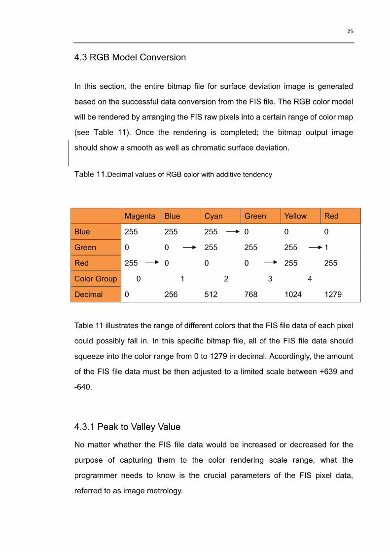
In this section, the entire bitmap file for surface deviation image is generated
based on the successful data conversion from the FIS file. The RGB color model
will be rendered by arranging the FIS raw pixels into a certain range of color map
(see Table 11). Once the rendering is completed; the bitmap output image
should show a smooth as well as chromatic surface deviation.
Table 11.Decimal values of RGB color with additive tendency
Magenta Blue Cyan Green Yellow Red
Blue 255 255 255 0 0 0
Green 0 0 255 255 255 1
Red 255 0 0 0 255 255
Color Group 0 1 2 3 4
Decimal 0 256 512 768 1024 1279
Table 11 illustrates the range of different colors that the FIS file data of each pixel
could possibly fall in. In this specific bitmap file, all of the FIS file data should
squeeze into the color range from 0 to 1279 in decimal. Accordingly, the amount
of the FIS file data must be then adjusted to a limited scale between +639 and
-640.
4.3.1 Peak to Valley Value
No matter whether the FIS file data would be increased or decreased for the
purpose of capturing them to the color rendering scale range, what the
programmer needs to know is the crucial parameters of the FIS pixel data,
referred to as image metrology.
26
The concept of Peak to Valley (P-V) value is thus required to be introduced. A
P-V value in terms of optics is the difference between the top and bottom area on
a surface. The Peak to Valley criterion has been widely used in the optic field for
the measurement of surface quality and its flatness [13]. The use of P-V value in
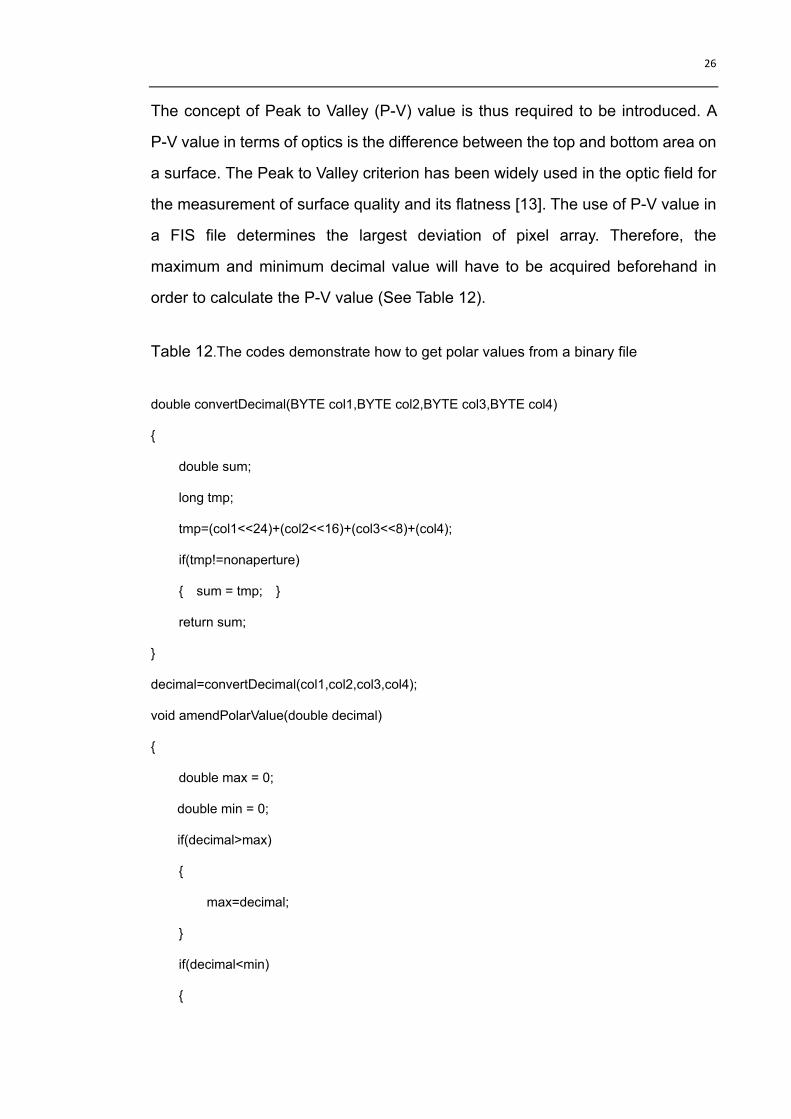
a FIS file determines the largest deviation of pixel array. Therefore, the
maximum and minimum decimal value will have to be acquired beforehand in
order to calculate the P-V value (See Table 12).
Table 12.The codes demonstrate how to get polar values from a binary file
double convertDecimal(BYTE col1,BYTE col2,BYTE col3,BYTE col4)
{
double sum;
long tmp;
tmp=(col1<<24)+(col2<<16)+(col3<<8)+(col4);
if(tmp!=nonaperture)
{ sum = tmp; }
return sum;
}
decimal=convertDecimal(col1,col2,col3,col4);
void amendPolarValue(double decimal)
{
double max = 0;
double min = 0;
if(decimal>max)
{
max=decimal;
}
if(decimal<min)
{
27
min=decimal;
}
}
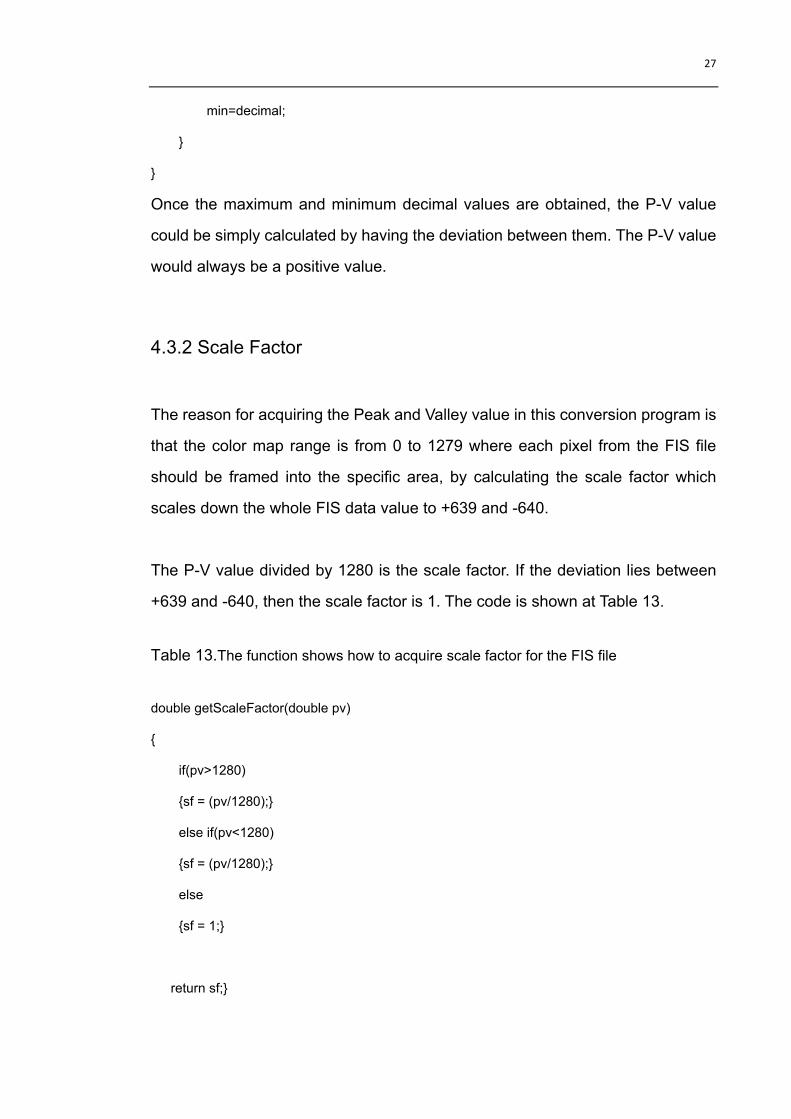
Once the maximum and minimum decimal values are obtained, the P-V value
could be simply calculated by having the deviation between them. The P-V value
would always be a positive value.
4.3.2 Scale Factor
The reason for acquiring the Peak and Valley value in this conversion program is
that the color map range is from 0 to 1279 where each pixel from the FIS file
should be framed into the specific area, by calculating the scale factor which
scales down the whole FIS data value to +639 and -640.
The P-V value divided by 1280 is the scale factor. If the deviation lies between
+639 and -640, then the scale factor is 1. The code is shown at Table 13.
Table 13.The function shows how to acquire scale factor for the FIS file
double getScaleFactor(double pv)
{
if(pv>1280)
{sf = (pv/1280);}
else if(pv<1280)
{sf = (pv/1280);}
else
{sf = 1;}
return sf;}

28
The next step is to ensure that the pixel data have been trapped in the range
from +639 to -640 by taking all the pixel values divided by scale factor. It is worth
noting that while the scale factor extends or curtails the pixel bytes of the FIS file,
it also decreases the precision of the output image in bitmap file; however, the
surface deviation still remains observational.
At this stage of data modification, all the compressed pixel values will have to
shift into the range from 0 to 1279 to match the Pseudo-color scale. The codes
can be seen from Table 14:
Table 14.The functions illustrate how to shift all the data to 0-1279
int trapDecimal(double decimal,double sf)
{
return (int)(decimal/sf) ;
}
int min1 = (int)(min/sf) ;
int shiftDecimal(int val1,int min1)
{
if( (min<0) | (min >0))
{ val1 = val1-min1; }
else
val1 ;
return val1;
}

29
4.3.3 RGB Color Rendering
The final step is to operate a serial of pixel byte to byte modification according to
the color map table (See Table 11). The code in Table 15 below enables every
single edited pixel to write into the bitmap file.
Table 15.This function depicts RGB color rendering for each pixel from converted FIS
data
pixel *getPixel(int val)
{
pixel *pxl=NULL;
pxl=(pixel *)malloc(sizeof(struct pixelDef));
if(NULL==pxl)
{
printf("Fail to allocate appointed memory\n");
exit(1);
}
if(val>=0 && val<256)
{
pxl->blue=255;
pxl->green=0;
pxl->red=255-val;
}
else if(val>=256 && val<512)
{
pxl->blue=255;
pxl->green=val-256;
pxl->red=0;

30
}
else if(val>=512 && val<768)
{
pxl->blue=767-val; /* 255-(val-512) */
pxl->green=255;
pxl->red=0;
}
else if(val>=768 && val<1024)
{
pxl->blue=0;
pxl->green=255;
pxl->red=val-768;
}
else if(val>=1024 && val<1279)
{
pxl->blue=0;
pxl->green=1279-val; /* 255-(val-1024) */
pxl->red=255;
}
else
{
pxl->blue=0;
pxl->green=1;
pxl->red=255;
}
return pxl;
}
When RGB model rendering is completed successfully, the actual converted
bitmap output file as surface deviation image should look as in Figure 7.

31
Figure 7.The conversion BMP image from the FIS file with RGB color rendering

32
5. Summary
This thesis systematically introduced the background knowledge of computer data
conversion and general guidelines that then extend a third party program in later
chapters for conversion between FIS file and BMP file. Most people have more or less
experience with operating bitmap images, while few have a detailed concept of how
binary data is jigsawed to form up a pixel as well as how pixels are colored to render an
image. Therefore through the analysis of bitmap and FIS file, the study also explored
the structure of two dedicated binary files and the color model being used in order to
convert the output image as close to the original image as possible.
The empirical research was conducted by writing up a conversion program to fulfill the
conversion from the FIS file to the BMP file. For the clarity of programming, two parts of
code were compiled in a sequence of functionality. The first stage demonstrated the
feasibility of the FIS file converted to a BMP file with data precision and its non-aperture
white background. After the successful conversion, the output image is not for optical
observation but proved the possibility of conversion from FIS file hexadecimal bytes to
BMP file hexadecimal bytes.
The result of second stage was to create an image which should be visually smooth and
make deviational observation possible. By taking advantage of scaling metrology, all the
pixel values were framed in a certain range, in this case 0 to 1279. The whole process
of BMP color resetting was carried out inside the range. The problem in this image was
that the background color should give white. There were still tiny errors in the program
when dealing with the data compression in FIS file. However, the background color
editing could be excluded from the scope of this research due to it is non-aperture and
senseless to the conversion as well as image observation.

33
References
[1] ODLIS —Online Dictionary forLibrary and Information Science
[www-document]. Available at: http://lu.com/odlis/odlis_d.cfm (accessed 14 June
2010)
[2] Data Conversion [www-document].
Available at: http://en.wikipedia.org/wiki/Data_conversion (accessed 14 June 2010)
[3] Chikofsky, E.J. and J.H. Cross II, 1990, “Reverse Engineering and Design Recovery:
A Taxonomy in IEEE Software”, IEEE Computer Society, pp. 13–17.
[4] Warden, R., 1992, “Software Reuse and Reverse Engineering in Practice”, London,
England: Chapman & Hall, pp.283–305.
[5] James, D. Foley., 1995, “Computer Graphics: Principles and Practice.”,
Addison-Wesley Professional, p.13.
[6] Description of the guidelines for selecting the appropriate picture format in an Office
program [www-document].
Available at: http://support.microsoft.com/kb/320314 (accessed 14 June 2010)
[7] [www-document].
Available at: http://www.digicamsoft.com/BMP/BMP.html (accessed 07 May 2010)
[8] [www-document].
Available at: http://atlc.sourceforge.net/BMP.html#_toc381201082 (accessed 11 May
2010)

34
[9] Isaac, N., 1704/1952, “Opticks: 4th Edition”, Dover, New York, p. 247.
[10] Donald, H. and M. Pauline, B., 1997, “Computer Graphics: C Version”, New Jersey,
USA: Prentice Hall, Inc., p. 572.
[11] Goldstein, E.B., 1989, “Sensation and Perception”, California, USA : Brooks/Cole, p.
86.
[12] [www-document].
Available at: http://msdn.microsoft.com/en-us/vstudio/aa700918.aspx (accessed 14
June 2010)
[13] What is an optical surface figure? [www-document].
Available at: http://optical-technologies.info/?tag=peak-to-valley-vs-rms (accessed
14 June 2010)

35
Appendix A: Table of BMP File Content
Offset Field Size
(byte)
Content
Bitmap
File
Header
0000h identifier 2 the characters indentifying bitmap
‘BM’ – windows 3.1x, 95, NT…
‘BA’ – os/2 bitmap array
‘CI’ – os/2 color icon
‘CP’ – os/2 color pointer
‘IC’ – os/2 icon
‘PT’ – os/2 pointer
0002h file size 4 complete file size in bytes
0006h reserved 4 reserved for later use
000ah bitmap data
offset
4 offset from beginning of file to the beginning of the
bitmap data
000eh bitmap
header size
4 length of the bitmap info header used to describe the bitmap colors, compression, the following sizes are possible:
28h-windows 3.1x, 95, NT…
0ch-os/2 1.x
f0h-os/2 2.x
0012h width 4 horizontal width of bitmap in pixels
0016h height 4 vertical height of bitmap in pixels
001ah planes 2 number of planes in this bitmap

36
Bitmap
Info
Header
001ch bits per pixel 2 bits per pixel used to store palette entry
information, his also identifies in an indirect way
the number of possible colors. possible values
are:
1-monochrome bitmap
4-16 color bitmap
8-256 color bitmap
16-16bit (high color) bitmap
24-24bit (true color) bitmap
32-32bit (true color) bitmap
001eh compression 4 compression specifications. the following values
are possible:
0-none (also identified by bi_rgb)
1-rle 8-bit / pixel (also identified by bi_rle4)
2-rle 4-bit / pixel (also identified by bi_rle8)
3-bitfields (also identified by bi_bitfields)
0022h bitmap data
size
4 size of the bitmap data in bytes. this number must
be rounded to the next 4 byte boundary
0026h hresolution 4 horizontal resolution expressed in pixel per meter.
002ah vresolution 4 number of colors used by this bitmap. for a 8-bit /
pixel bitmap this will be 100h or 256
002eh colors 4 number of colors used by this bitmap. for a 8-bit /
pixel bitmap this will be 100h or 256

37
0032h important
colors
4 number of important colors. this number will be
equal to the number of colors when every color is
important
Palette
0036h palette n×4 the palette specification. for every entry in the
palette four bytes are used to describe the rgb
values of the color in the following way:
1 byte for blue component
1 byte for red component
1 byte for green component
1 byte filler which is set to zero
Bitmap
Array
0436h bitmap data x depending on the compression specifications, this
field contains all the bitmap data bytes which
represent indices in the color palette

38
Appendix B: Conversion Codes between
Hexadecimal Value and Decimal Value
#include <stdio.h>
#include <stdlib.h>
#include <string.h>
#define ERROR 1
#define FISHEXSIZE 8
#define BMPHEXSIZE 6
int hexTrans(char c);
int fisHexToDec(char *hex);
char bmpShift(char c);
int bmpHexToDec(char *hex);
void fisDecToHex(long data);
void bmpDecToHex(long data);
int main(void)
{
char *array=(char *)malloc(FISHEXSIZE);
array="00000080";
fisHexToDec(array);
/*char *array=(char *)malloc(BMPHEXSIZE);
array="000000";
bmpHexToDec(array);*/
/*fisDecToHex(1);
/*bmpDecToHex(0);*/
return 0;
}

39
int hexTrans(char c)
{
if(c>='0' && c<='9')
{
return (c-'0')%16;
}
else
{
return (c-'A'+10)%16;
}
}
int fisHexToDec(char *hex)
{
int i;
int j;
int k;
char t1=0;
char t2=0;
long tmp=1;
long sum=0;
char buf[FISHEXSIZE];
if(hex==NULL)
{
perror("Parameter uninitialized");
return ERROR;
}

40
for(i=FISHEXSIZE-1;i>=0;i-=2)
{
t1=*hex++;
t2=*hex++;
buf[i]=t2;
buf[i-1]=t1;
}
for(i=FISHEXSIZE-1,j=0;i>=0;i--,j++)
{
for(k=0,tmp=1;k<j;k++)
{
tmp<<=4;
}
sum=sum+tmp*hexTrans(buf[i]);
}
printf("%ld",sum);
return 0;
}
char bmpShift(char c)
{
char tmp=0;
switch(c)
{
case '0':
case '1': tmp=(char)(c+8);
break;

41
case '2': tmp='A';
break;
case '3': tmp='B';
break;
case '4': tmp='C';
break;
case '5': tmp='D';
break;
case '6': tmp='E';
break;
case '7': tmp='F';
break;
case '8': tmp='0';
break;
case '9': tmp='1';
break;
case 'A': tmp='2';
break;
case 'B': tmp='3';
break;
case 'C': tmp='4';
break;
case 'D': tmp='5';
break;
case 'E': tmp='6';
break;
case 'F': tmp='7';
break;
default: printf("bmpShift Error\n");
exit(ERROR);

42
}
return tmp;
}
int bmpHexToDec(char *hex)
{
int i;
int j;
int k;
long tmp=1;
long sum=0;
char buf[BMPHEXSIZE];
if(NULL==hex)
{
perror("Parameter uninitialized");
return ERROR;
}
for(i=0;i<BMPHEXSIZE;i++)
{
buf[i]=*hex++;
}
buf[0]=bmpShift(buf[0]);
for(i=BMPHEXSIZE-1,j=0;i>=0;i--,j++)
{
for(k=0,tmp=1;k<j;k++)
{

43
tmp<<=4;
}
sum=sum+tmp*hexTrans(buf[i]);
}
sum&=0x00FFFFFF;
switch(buf[0])
{
case '8':
case '9':
case 'A':
case 'B':
case 'C':
case 'D':
case 'E':
case 'F': sum*=-1;
}
printf("bmp file decimal: %ld",sum);
return 0;
}
void fisDecToHex(long data)
{
int i=FISHEXSIZE-1;
int arr[FISHEXSIZE];
char hex[]={'0','1','2','3','4','5','6','7','8','9','A','B','C','D','E','F'};
memset(arr,0,FISHEXSIZE);

44
if(data<0)
{
data=~data;
data++;
}
while(1)
{
arr[i]+=data%16; printf("\n%d:%d\n",i,arr[i]);
data/=16;
if(--i==0)
{
break;
}
}
arr[i]+=data;printf("%d:%d\n",i,arr[1]);
for(i=FISHEXSIZE-1;i>=0;i=i-2)
printf("%c%c",hex[arr[i-1]],hex[arr[i]]);
printf("\n");
}
void bmpDecToHex(long data)
{
int i=BMPHEXSIZE-1;
int arr[BMPHEXSIZE];
char hex[]={'0','1','2','3','4','5','6','7','8','9','A','B','C','D','E','F'};
memset(arr,0,BMPHEXSIZE);
while(1)
{
arr[i]=data%16;
data/=16;

45
if(--i==0)
{
break;
}
}
arr[i]=data;
arr[0]=(arr[0]+8)%16;
for(i=0;i<=BMPHEXSIZE-1;i++)
printf("%c",hex[arr[i]]);
printf("\n");
}