Embed Size (px)
Citation preview

A Design Methodology for the Implementation of a Fuzzy Logic
Traffic Controller Using FPGA Technology
Mandar Ambre, Bing W.Kwan and Leonard J.TungDepartment of Electrical & Computer Engineering
FAMU-FSU College of Engineering, Florida State University
THE HUNTSVILLE SIMULATION CONFERENCE HSC 2003

Outline• In this paper we suggest the use of state diagrams for
capturing a rule base of a fuzzy traffic control system.
• The fuzzy rule base for the controller is described using the state diagrams and the fuzzy inference based on the fuzzy rules is implemented using MATLAB code.
• The output of the MATLAB program is stored in a ROM for use in the VHDL code.
• A complete description of the system is assembled in VHDL and is synthesized using VHDL-based logic synthesis and Synopsys design compiler is used to perform logic synthesis

What is Fuzzy Logic?
• Fuzzy logic refers to a logical system that generalizes the crisp true-or-false concept to a matter of degree.
• Fuzzy logic provides the mechanism by which numerical and linguistic information can be incorporated in a systematic manner.

Need of Fuzzy Logic in Traffic Controllers
• Traffic signaling at a given intersection is not truly adaptive because the settings can only be altered manually or by traffic control center.
• One of the desirable features of traffic controllers is to dynamically effect the change of signal phase durations without looking up pre-compiled information.
• This problem can be solved by use of fuzzy traffic controllers which are capable of signaling adaptively at an intersection.

Basic Structure of a Fuzzy Traffic Controller

Components of Fuzzy Traffic Controller
• FUZZIFIER – Fuzzifier takes the crisp inputs to a fuzzy controller and converts them into fuzzy inputs.
• FUZZY RULE BASE – It consists of fuzzy IF-THEN rules that form the heart of a fuzzy inference system.
• FUZZY INFERENCE ENGINE - Fuzzy Inference Engine makes use of fuzzy logic principles to combine the fuzzy IF-THEN rules.
• DEFUZZIFIER – It extracts a crisp value from a fuzzy set.

Fuzzy Rule Base
IFIF--THEN rule base is used for fuzzy reasoning by THEN rule base is used for fuzzy reasoning by the fuzzy traffic controllerthe fuzzy traffic controller

Membership Functions
1
0 1
µLight HeavyMedium
1
0 1
µShort LongMedium
Green Phase Duration
(a) (b)
dNS(k), dEW(k)
•• In this paper for simplicity we have considered fuzzy In this paper for simplicity we have considered fuzzy controllers that involve a small number of fuzzy sets controllers that involve a small number of fuzzy sets with simple membership functions.with simple membership functions.
•• Fuzzy sets of traffic flow are labeled as “Light”, “ Fuzzy sets of traffic flow are labeled as “Light”, “ Medium” and “Heavy” and fuzzy sets “Short”, “Medium” Medium” and “Heavy” and fuzzy sets “Short”, “Medium” and “ Long” are associated with green phase duration.and “ Long” are associated with green phase duration.

Fuzzy Implementationµ
X
µ
Z
h1A
A B C A pB Cx
µ
X
µ
Zx
2Ah
B C D B C D1p 2p
X
µ
Zx
3A
C D E EDC p
( ) ( )2
2
1CBh
AChA−
+−=
( ) ( ) ccbhpwhereACp
ACAppCpc +−=
−+−−+
=26
1175 2
1
( ) ( )BChBDhA −+−= 22
22db
c+
=
( ) ( )2
2
3DChCEhA −+−=
( ) ( ) ccdhpwhereECp
ECEppCpc +−=
−+−−+
=26
1175 2
3
A moments method is proposed as another form of defuzzification. This scheme weights the individual fuzzy sets with the respective areas. The ordinate values of the center of the fuzzy sets are used as the moments

Design Methodology• The high level description of the fuzzy rule base needs to be
converted to VHDL code.
• To simplify the process we design the fuzzy controller using MATLAB.
• The output of the MATLAB program is stored in the ROM for use in the VHDL code.
• A complete description of the system is assembled in VHDL and is synthesized using VHDL-based logic synthesis.
• Synopsys design compiler is used to perform logic synthesis.

MATLAB Implementation
• Moments method is used to find the general form of the X co-ordinate value of the centroid or the fuzzy lengths given by
where Ai- Area and Zi- center of area for various fuzzy sets from 1 to n
• Generated MATLAB plot for Fuzzy system with 3 Fuzzy sets
• Wrote a MATLAB code that generates plot for n Fuzzy sets
∑
∑
=
== n
i
i
n
i
ii
MA
Z
ZA
Z
1
1

MATLAB plot for Fuzzy System with Three Fuzzy sets

Block Diagram of the System
Tns- Traffic in North-South DirectionTew- Traffic in East-West Direction

ROM Implementation
• Output values that are obtained by using MATLAB plot are stored in the ROM.
• The output of the ROM is given to the main programming module.

Different Stages of Hardware Implementation

RTL Design
• Developing block- and chip-level specifications
• Developing and optimizing new Register Transfer Level (RTL) code
• Developing intelligent Testbenches
• Improving verification methodology and coverage
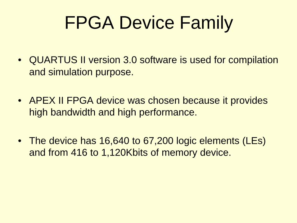
FPGA Device Family
• QUARTUS II version 3.0 software is used for compilation and simulation purpose.
• APEX II FPGA device was chosen because it provides high bandwidth and high performance.
• The device has 16,640 to 67,200 logic elements (LEs) and from 416 to 1,120Kbits of memory device.

APEX II SOPC

Verification

Testbench Waveforms

Synthesis
• Synopsys Design Compiler is used to perform logic synthesis.
• Design is optimized for Area as well as Timing.
• Synopsys Design Analyzer tool is used to obtain gate level representation of the circuit and generate report files for area, timing and power dissipation.

Gate Level Representation of the circuit

Conclusion• The high level description of the fuzzy rule base is
converted to VHDL code.
• To simplify the process we design the fuzzy controller using MATLAB.
• The output of the MATLAB program is stored in the ROM for use in the VHDL code.
• A complete description of the system is assembled in VHDL and is synthesized using VHDL-based logic synthesis.
• Synopsys design compiler is used to perform logic synthesis.