Embed Size (px)
Citation preview
45
This chapter focuses on a new design technique for the analysis and design of data integrationprocesses. This technique uses a graphical process modeling view of data integration similar tothe graphical view an entity-relationship diagram provides for data models.
The Business Case for a New Design ProcessThere is a hypothesis to the issue of massive duplication of data integration processes, which is asfollows:
C H A P T E R 3
A Design Technique:Data IntegrationModeling
One of the main reasons why there is massive replication of data integration processes inmany organizations is the fact that there is no visual method of “seeing” what data integrationprocesses currently exist and what is needed. This is similar to the problem that once plagued thedata modeling discipline.
In the early 1980s, many organizations had massive duplication of customer and transac-tional data. These organizations could not see the “full picture” of their data environment and themassive duplication. Once organizations began to document and leverage entity-relationship dia-grams (visual representations of a data model), they were able to see the massive duplication andthe degree of reuse of existing tables increased as unnecessary duplication decreased.
The development of data integration processes is similar to those in database development.In developing a database, a blueprint, or model of the business requirements, is necessary toensure that there is a clear understanding between parties of what is needed. In the case of dataintegration, the data integration designer and the data integration developer need that blueprint orproject artifact to ensure that the business requirements in terms of sources, transformations, and
If you do not see a process, you will replicate that process.
Copyright 2011 by International Business Machines Corp.
46 Chapter 3 A Design Technique: Data Integration Modeling
targets that are needed to move data have been clearly communicated via a common, consistentapproach. The use of a process model specifically designed for data integration will accomplishthat requirement.
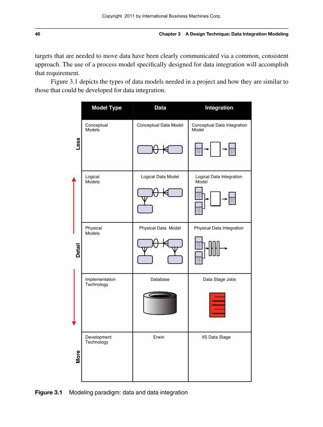
Figure 3.1 depicts the types of data models needed in a project and how they are similar tothose that could be developed for data integration.
IIS Data StageErwinDevelopmentTechnology
ImplementationTechnology
LogicalModels
ConceptualModels
IntegrationDataModel Type
Physical
Mo
re
Models
IntegrationDataModel Type
Conceptual Data Model
Logical Data Model
Database Data Stage Jobs
Physical Data Model
Logical Data Integration Model
Physical Data Integration
Conceptual Data IntegrationModel
Det
ail
Les
s
Figure 3.1 Modeling paradigm: data and data integration
Copyright 2011 by International Business Machines Corp.
Improving the Development Process 47
The usual approach for analyzing, designing, and building ETL or data integrationprocesses on most projects involves a data analyst documenting the requirements for source-to-target mapping in Microsoft® Excel® spreadsheets. These spreadsheets are given to an ETL devel-oper for the design and development of maps, graphs, and/or source code.
Documenting integration requirements from source systems and targets manually into atool like Excel and then mapping them again into an ETL or data integration package has beenproven to be time-consuming and prone to error. For example:
• Lost time—It takes a considerable amount of time to copy source metadata from sourcesystems into an Excel spreadsheet. The same source information must then be rekeyedinto an ETL tool. This source and target metadata captured in Excel is largely non-reusable unless a highly manual review and maintenance process is instituted.
• Nonvalue add analysis—Capturing source-to-target mappings with transformationrequirements contains valuable navigational metadata that can be used for data lineageanalysis. Capturing this information in an Excel spreadsheet does not provide a cleanautomated method of capturing this valuable information.
• Mapping errors—Despite our best efforts, manual data entry often results in incorrectentries, for example, incorrectly documenting an INT data type as a VARCHAR in anExcel spreadsheet will require a data integration designer time to analyze and correct.
• Lack of standardization: inconsistent levels of detail—The data analysts who per-form the source-to-target mappings have a tendency to capture source/transform/targetrequirements at different levels of completeness depending on the skill and experienceof the analyst. When there are inconsistencies in the level of detail in the requirementsand design of the data integration processes, there can be misinterpretations by thedevelopment staff in the source-to-target mapping documents (usually Excel), whichoften results in coding errors and lost time.
• Lack of standardization: inconsistent file formats—Most environments have mul-tiple extracts in different file formats. The focus and direction must be toward the con-cept of read once, write many, with consistency in extract, data quality, transformation,and load formats. The lack of a standardized set of extracts is both a lack of techniqueand often a result of a lack of visualization of what is in the environment.
To improve the design and development efficiencies of data integration processes, in termsof time, consistency, quality, and reusability, a graphical process modeling design technique fordata integration with the same rigor that is used in developing data models is needed.
Improving the Development ProcessProcess modeling is a tried and proven approach that works well with Information Technologyapplications such as data integration. By applying a process modeling technique to data integra-tion, both the visualization and standardization issues will be addressed. First, let’s review thetypes of process modeling.
Copyright 2011 by International Business Machines Corp.
48 Chapter 3 A Design Technique: Data Integration Modeling
Leveraging Process Modeling for Data IntegrationProcess modeling is a means of representing the interrelated processes of a system at any level ofdetail, using specific types of diagrams that show the flow of data through a series of processes.Process modeling techniques are used to represent specific processes graphically for clearerunderstanding, communication, and refinement between the stakeholders that design and developsystem processes.
Process modeling unlike data modeling has several different types of process models basedon the different types of process interactions. These different model types include processdependency diagrams, structure hierarchy charts, and data flow diagrams. Data flow diagram-ming, which is one of the best known of these process model types, is further refined into severaldifferent types of data flow diagrams, such as context diagrams, Level 0 and Level 1 diagramsand “leaf-level” diagrams that represent different levels and types of process and data flow.
By leveraging the concepts of different levels and types of process modeling, we havedeveloped a processing modeling approach for data integration processes, which is as follows:
Data integration modeling is a process modeling technique that is focused on engineeringdata integration processes into a common data integration architecture.
Overview of Data Integration ModelingData integration modeling is a technique that takes into account the types of models needed basedon the types of architectural requirements for data integration and the types of models neededbased on the Systems Development Life Cycle (SDLC).
Modeling to the Data Integration ArchitectureThe types of process models or data integration models are dependent on the types of processingneeded in the data integration reference architecture. By using the reference architecture as aframework, we are able to create specific process model types for the discrete data integrationprocesses and landing zones, as demonstrated in Figure 3.2.
Copyright 2011 by International Business Machines Corp.

Overview of Data Integration Modeling 49
Clean StagingExtract/Publish Initial Staging Data Quality Load-ReadyPublish
LoadTransformation
Retail LogicalExtract Model
Commercial Logical Extract
Model
Demand DepositLogical Extract
Model
Bad Transactions0101 3443434 Missing Fields0304 535355 Referential Integrity0101 3443434 Missing Fields0304 535355 Referential Integrity
Bus DQCheck
Tech DQChecks
ErrorHandling
ConformDeposit
Data
ConformLoanData
Involved Party Logical Load
Model
Event Logical Load
Model
Figure 3.2 Designing models to the architecture
Together, these discrete data integration layers become process model types that form acomplete data integration process. The objective is to develop a technique that will lead thedesigner to model data integration processes based on a common set of process types.
Data Integration Models within the SDLCData integration models follow the same level of requirement and design abstraction refinementthat occurs within data models during the SDLC. Just as there are conceptual, logical, and physi-cal data models, there are conceptual, logical, and physical data integration requirements that needto be captured at different points in the SDLC, which could be represented in a process model.
The following are brief descriptions of each of the model types. A more thorough definitionalong with roles, steps, and model examples is reviewed later in the chapter.
• Conceptual data integration model definition—Produces an implementation-freerepresentation of the data integration requirements for the proposed system that willserve as a basis for determining how they are to be satisfied.
• Logical data integration model definition—Produces a detailed representation of thedata integration requirements at the data set (entity/table)level, which details the trans-formation rules and target logical data sets (entity/tables). These models are still consid-ered to be technology-independent.
The focus at the logical level is on the capture of actual source tables and proposed tar-get stores.
• Physical data integration model definition—Produces a detailed representation ofthe data integration specifications at the component level. They should be representedin terms of the component-based approach and be able to represent how the data willoptimally flow through the data integration environment in the selected developmenttechnology.
Copyright 2011 by International Business Machines Corp.

50 Chapter 3 A Design Technique: Data Integration Modeling
Process 1 Process 2 Process 3
ContextDiagram
Figure 3.3 A traditional process model: data flow diagram
PhysicalSource System
Extract
PhysicalExtraction
Models
ConceptualData Integration Model
Conceptual DataIntegration Modeling
High-Level LogicalData Integration Model
LogicalExtraction Model
Physical DataIntegration Modeling
LogicalLoad Model
Logical DataIntegration Modeling
PhysicalSource System
ExtractModels
PhysicalExtraction
Models
PhysicalSubject Area
LoadModels
PhysicalCommon Components
Model(s)
LogicalData Quality Model
LogicalTransform Model
Figure 3.4 Data integration models by the Systems Development Life Cycle
Structuring Models on the Reference ArchitectureStructuring data models to a Systems Development Life Cycle is a relatively easy process. Thereis usually only one logical model for a conceptual data model and there is only one physical datamodel for a logical data model. Even though entities may be decomposed or normalized within amodel, there is rarely a need to break a data model into separate models.
Process models have traditionally been decomposed further down into separate discretefunctions. For example, in Figure 3.3, the data flow diagram’s top process is the context diagram,which is further decomposed into separate functional models.
Data integration models are decomposed into functional models as well, based on the dataintegration reference architecture and the phase of the Systems Development Life Cycle.
Figure 3.4 portrays how conceptual, logical, and physical data integration models are bro-ken down.
Copyright 2011 by International Business Machines Corp.
Logical Data Integration Models 51
Model Name: CIA Data Integration ModelProject: Customer Interaction AnalysisLife Cycle Type: ConceptualDI Architecture Layer: N/A
Retail LoanApplication
Commercial LoanApplication
Demand DepositApplication
BankData Warehouse
Loan andTransaction DataQuality Transform
Conforming
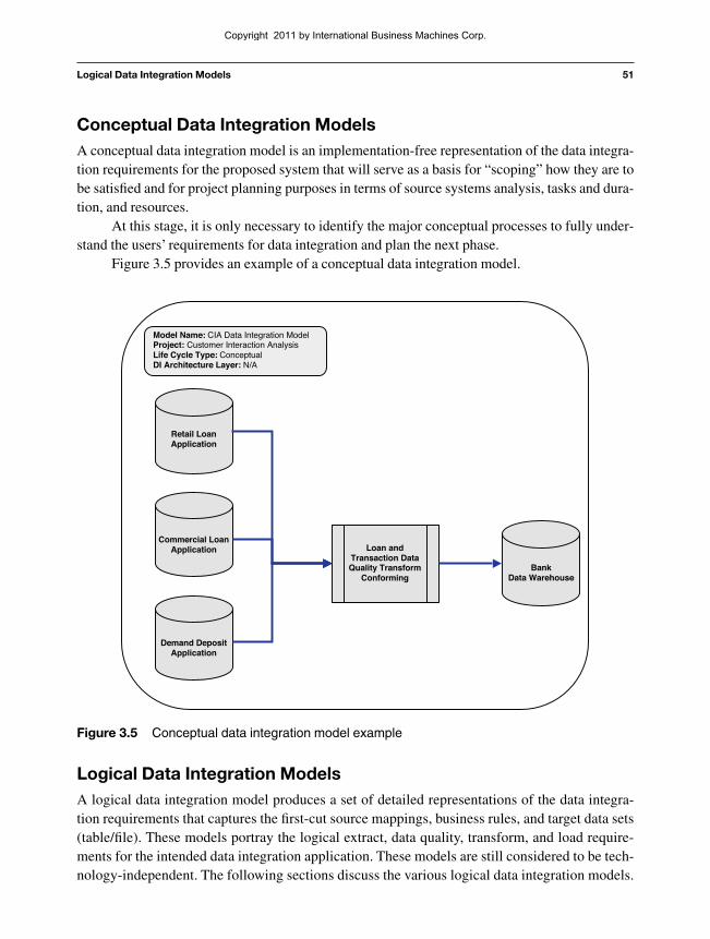
Figure 3.5 Conceptual data integration model example
Conceptual Data Integration ModelsA conceptual data integration model is an implementation-free representation of the data integra-tion requirements for the proposed system that will serve as a basis for “scoping” how they are tobe satisfied and for project planning purposes in terms of source systems analysis, tasks and dura-tion, and resources.
At this stage, it is only necessary to identify the major conceptual processes to fully under-stand the users’ requirements for data integration and plan the next phase.
Figure 3.5 provides an example of a conceptual data integration model.
Logical Data Integration ModelsA logical data integration model produces a set of detailed representations of the data integra-tion requirements that captures the first-cut source mappings, business rules, and target data sets(table/file). These models portray the logical extract, data quality, transform, and load require-ments for the intended data integration application. These models are still considered to be tech-nology-independent. The following sections discuss the various logical data integration models.
Copyright 2011 by International Business Machines Corp.
52 Chapter 3 A Design Technique: Data Integration Modeling
Model Name: CIA Data Integration ModelProject: Customer Interaction AnalysisLife Cycle Type: Logical, High-LevelDI Architecture Layer: N/A
Retail LoanApplication
CommercialLoan
Application
DemandDeposit
Application
Retail LogicalExtract Model
Commercial Logical Extract
Model
Demand DepositLogical Extract
Model
Bad Transactions0101 3443434 Missing Fields0304 535355 Referential Integrity0101 3443434 Missing Fields0304 535355 Referential Integrity
Bus DQCheck
Tech DQChecks
ErrorHandling
ConformDeposit
Data
ConformLoanData
Involved Party Logical Load
Model
Event
Bank DataWarehouse
Logical LoadModel
Figure 3.6 Logical high-level data integration model example
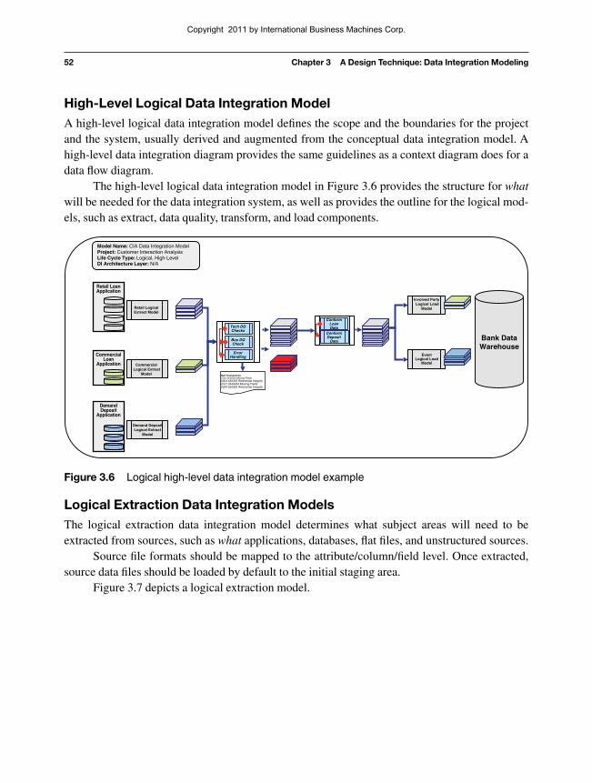
High-Level Logical Data Integration ModelA high-level logical data integration model defines the scope and the boundaries for the projectand the system, usually derived and augmented from the conceptual data integration model. Ahigh-level data integration diagram provides the same guidelines as a context diagram does for adata flow diagram.
The high-level logical data integration model in Figure 3.6 provides the structure for whatwill be needed for the data integration system, as well as provides the outline for the logical mod-els, such as extract, data quality, transform, and load components.
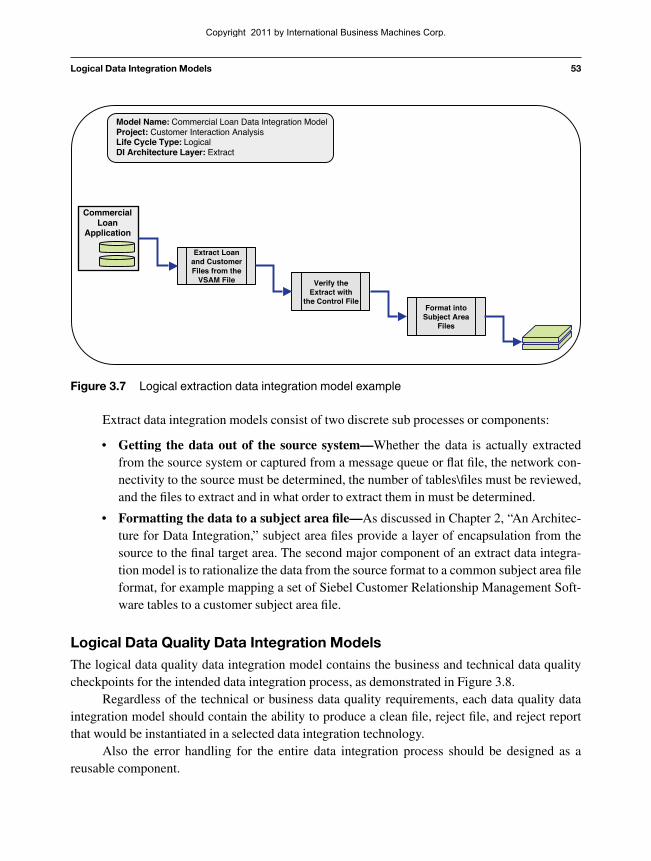
Logical Extraction Data Integration ModelsThe logical extraction data integration model determines what subject areas will need to beextracted from sources, such as what applications, databases, flat files, and unstructured sources.
Source file formats should be mapped to the attribute/column/field level. Once extracted,source data files should be loaded by default to the initial staging area.
Figure 3.7 depicts a logical extraction model.
Copyright 2011 by International Business Machines Corp.
Logical Data Integration Models 53
Model Name: Commercial Loan Data Integration ModelProject: Customer Interaction AnalysisLife Cycle Type: LogicalDI Architecture Layer: Extract
Extract Loanand CustomerFiles from the
VSAM File
CommercialLoan
Application
Verify theExtract with
the Control FileFormat into
Subject AreaFiles
Figure 3.7 Logical extraction data integration model example
Extract data integration models consist of two discrete sub processes or components:
• Getting the data out of the source system—Whether the data is actually extractedfrom the source system or captured from a message queue or flat file, the network con-nectivity to the source must be determined, the number of tables\files must be reviewed,and the files to extract and in what order to extract them in must be determined.
• Formatting the data to a subject area file—As discussed in Chapter 2, “An Architec-ture for Data Integration,” subject area files provide a layer of encapsulation from thesource to the final target area. The second major component of an extract data integra-tion model is to rationalize the data from the source format to a common subject area fileformat, for example mapping a set of Siebel Customer Relationship Management Soft-ware tables to a customer subject area file.
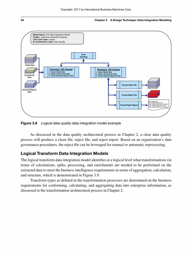
Logical Data Quality Data Integration ModelsThe logical data quality data integration model contains the business and technical data qualitycheckpoints for the intended data integration process, as demonstrated in Figure 3.8.
Regardless of the technical or business data quality requirements, each data quality dataintegration model should contain the ability to produce a clean file, reject file, and reject reportthat would be instantiated in a selected data integration technology.
Also the error handling for the entire data integration process should be designed as areusable component.
Copyright 2011 by International Business Machines Corp.
54 Chapter 3 A Design Technique: Data Integration Modeling
As discussed in the data quality architectural process in Chapter 2, a clear data qualityprocess will produce a clean file, reject file, and reject report. Based on an organization’s datagovernance procedures, the reject file can be leveraged for manual or automatic reprocessing.
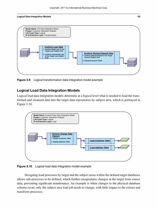
Logical Transform Data Integration ModelsThe logical transform data integration model identifies at a logical level what transformations (interms of calculations, splits, processing, and enrichment) are needed to be performed on theextracted data to meet the business intelligence requirements in terms of aggregation, calculation,and structure, which is demonstrated in Figure 3.9.
Transform types as defined in the transformation processes are determined on the businessrequirements for conforming, calculating, and aggregating data into enterprise information, asdiscussed in the transformation architectural process in Chapter 2.
Model Name: CIA Data Integration ModelProject: Customer Interaction AnalysisLife Cycle Type: LogicalDI Architecture Layer: Data Quality
Retail Data
CommercialData
Demand DepositData
Bad Transactions0101 3443434 Missing Fields0304 535355 Referential Integrity0101 3443434 Missing Fields0304 535355 Referential Integrity
Technical DQ Checks1. Check Retail Data2. Check Commercial Data3. Check Demand Deposit Data
ErrorHandling
Business DQ Checks1. Check Retail Data2. Check Commercial Data3. Check Demand Deposit Data
Format Clean File
Format Reject File
Format Reject Report
Figure 3.8 Logical data quality data integration model example
Copyright 2011 by International Business Machines Corp.
Logical Data Integration Models 55
Model Name: CIA Data Integration ModelProject: Customer Interaction AnalysisLife Cycle Type: LogicalDI Architecture Layer: Transformation
Conform Loan Data1. Conform Retail Loan to the
Target Loan Subject Area
2. Conform Commercial Loanto the Target Loan SubjectArea
Conform Demand Deposit Data1. Conform Demand Deposit to the Target
Account Subject Area
2. Calculate Account Totals
Figure 3.9 Logical transformation data integration model example
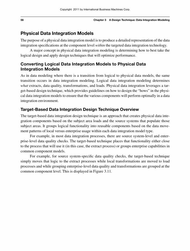
Model Name: Involved Party Data Integration ModelProject: Customer Interaction AnalysisLife Cycle Type: LogicalDI Architecture Layer: Load
Perform Change DataCapture
1. Update Customer Table
2. Update Address TableLoad Customer Table
Load Address Table
Figure 3.10 Logical load data integration model example
Logical Load Data Integration ModelsLogical load data integration models determine at a logical level what is needed to load the trans-formed and cleansed data into the target data repositories by subject area, which is portrayed inFigure 3.10.
Designing load processes by target and the subject areas within the defined target databasesallows sub-processes to be defined, which further encapsulates changes in the target from sourcedata, preventing significant maintenance. An example is when changes to the physical databaseschema occur, only the subject area load job needs to change, with little impact to the extract andtransform processes.
Copyright 2011 by International Business Machines Corp.
56 Chapter 3 A Design Technique: Data Integration Modeling
Physical Data Integration ModelsThe purpose of a physical data integration model is to produce a detailed representation of the dataintegration specifications at the component level within the targeted data integration technology.
A major concept in physical data integration modeling is determining how to best take thelogical design and apply design techniques that will optimize performance.
Converting Logical Data Integration Models to Physical DataIntegration ModelsAs in data modeling where there is a transition from logical to physical data models, the sametransition occurs in data integration modeling. Logical data integration modeling determineswhat extracts, data quality, transformations, and loads. Physical data integration leverages a tar-get-based design technique, which provides guidelines on how to design the “hows” in the physi-cal data integration models to ensure that the various components will perform optimally in a dataintegration environment.
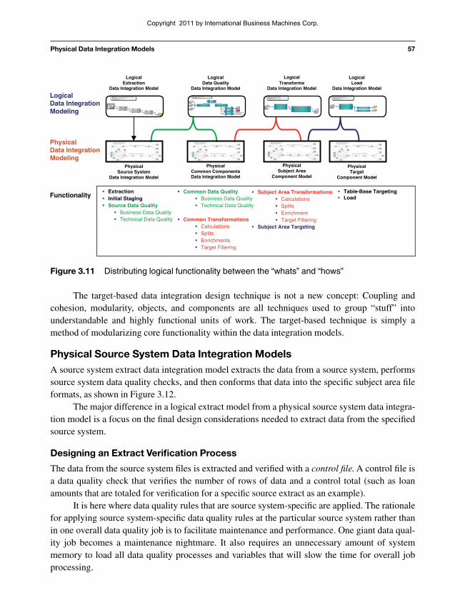
Target-Based Data Integration Design Technique OverviewThe target-based data integration design technique is an approach that creates physical data inte-gration components based on the subject area loads and the source systems that populate thosesubject areas. It groups logical functionality into reusable components based on the data move-ment patterns of local versus enterprise usage within each data integration model type.
For example, in most data integration processes, there are source system-level and enter-prise-level data quality checks. The target-based technique places that functionality either closeto the process that will use it (in this case, the extract process) or groups enterprise capabilities incommon component models.
For example, for source system-specific data quality checks, the target-based techniquesimply moves that logic to the extract processes while local transformations are moved to loadprocesses and while grouping enterprise-level data quality and transformations are grouped at thecommon component level. This is displayed in Figure 3.11.
Copyright 2011 by International Business Machines Corp.
Physical Data Integration Models 57
Model Name: Involved Party Data Integration ModelProject: Customer Interaction AnalysisLife Cycle Type: LogicalDI Architecture Layer: Load
Perform Change Data Capture
1. Update Customer Table
2. Update Address Table
Perform Change Data Capture
1. Update Customer Table
2. Update Address Table Load Customer TableLoad Customer Table
Load Address TableLoad Address Table
Model Name: CIA Data Integration ModelProject: Customer Interaction AnalysisLife Cycle Type: LogicalDI Architecture Layer: Transformation
Conform Loan Data1. Conform Retail Loan to the
Target Loan Subject Area
2. Conform Commercial Loan to the Target Loan Subject Area
Conform Loan Data1. Conform Retail Loan to the
Target Loan Subject Area
2. Conform Commercial Loan to the Target Loan Subject Area
Conform Demand Deposit Data1. Conform Demand Deposit to the Target
Account Subject Area
2. Calculate Account Totals
Conform Demand Deposit Data1. Conform Demand Deposit to the Target
Account Subject Area
2. Calculate Account Totals
Model Name: Commercial Loan Data Integration ModelProject: Customer Interaction AnalysisLife Cycle Type: LogicalDI Architecture Layer: Extract
Extract Loan and Customer files from the
VSAM file
Commercial Loan
Application
Verify the extract with the
Control FileFormat into
Subject Area files
LogicalExtraction
Data Integration Model
LogicalData Quality
Data Integration Model
LogicalTransforms
Data Integration Model
LogicalLoad
Data Integration Model
LogicalData IntegrationModeling
PhysicalData IntegrationModeling
PhysicalSource System
Data Integration Model
PhysicalCommon ComponentsData Integration Model
PhysicalSubject Area
Component Model
PhysicalTarget
Component Model
ExtractionInitial StagingSource Data Quality
Business Data QualityTechnical Data Quality
Subject Area TransformationsCalculationsSplitsEnrichmentTarget Filtering
Subject Area Targeting
Table-Base TargetingLoad
Common Data QualityBusiness Data QualityTechnical Data Quality
Common TransformationsCalculationsSplitsEnrichmentsTarget Filtering
Functionality
Model Name: CIA Data Integration ModelProject: Customer Interaction AnalysisLife Cycle Type: LogicalDI Architecture Layer: Data Quality
Retail Data
CommercialData
Demand Deposit Data
Bad TransactionssdleiFgnissiM43434431010
0304 535355 Referential Integrity0101 3443434 Missing Fields0304 535355 Referential Integrity
Technical DQ ChecksTechnical DQ Checks1.Check Retail Data1.Check Retail Data2. Check Commercial Data2. Check Commercial Data3. Check Demand Deposit Data3. Check Demand Deposit Data
Error Error HandlingHandling
Business DQ ChecksBusiness DQ Checks1.Check Retail Data1.Check Retail Data2. Check Commercial Data2. Check Commercial Data3. Check Demand Deposit Data3. Check Demand Deposit Data
Format Clean FileFormat Clean File
Format Reject FileFormat Reject File
Format Reject ReportFormat Reject Report
Figure 3.11 Distributing logical functionality between the “whats” and “hows”
The target-based data integration design technique is not a new concept: Coupling andcohesion, modularity, objects, and components are all techniques used to group “stuff” intounderstandable and highly functional units of work. The target-based technique is simply amethod of modularizing core functionality within the data integration models.
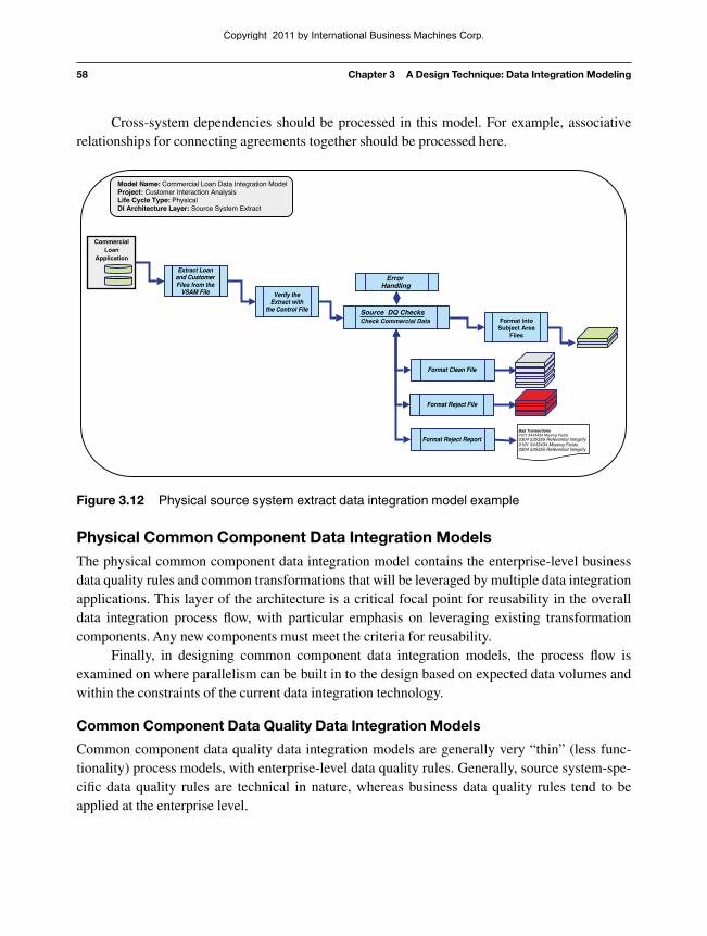
Physical Source System Data Integration ModelsA source system extract data integration model extracts the data from a source system, performssource system data quality checks, and then conforms that data into the specific subject area fileformats, as shown in Figure 3.12.
The major difference in a logical extract model from a physical source system data integra-tion model is a focus on the final design considerations needed to extract data from the specifiedsource system.
Designing an Extract Verification Process
The data from the source system files is extracted and verified with a control file. A control file isa data quality check that verifies the number of rows of data and a control total (such as loanamounts that are totaled for verification for a specific source extract as an example).
It is here where data quality rules that are source system-specific are applied. The rationalefor applying source system-specific data quality rules at the particular source system rather thanin one overall data quality job is to facilitate maintenance and performance. One giant data qual-ity job becomes a maintenance nightmare. It also requires an unnecessary amount of systemmemory to load all data quality processes and variables that will slow the time for overall jobprocessing.
Copyright 2011 by International Business Machines Corp.
58 Chapter 3 A Design Technique: Data Integration Modeling
Cross-system dependencies should be processed in this model. For example, associativerelationships for connecting agreements together should be processed here.
Physical Common Component Data Integration ModelsThe physical common component data integration model contains the enterprise-level businessdata quality rules and common transformations that will be leveraged by multiple data integrationapplications. This layer of the architecture is a critical focal point for reusability in the overalldata integration process flow, with particular emphasis on leveraging existing transformationcomponents. Any new components must meet the criteria for reusability.
Finally, in designing common component data integration models, the process flow isexamined on where parallelism can be built in to the design based on expected data volumes andwithin the constraints of the current data integration technology.
Common Component Data Quality Data Integration Models
Common component data quality data integration models are generally very “thin” (less func-tionality) process models, with enterprise-level data quality rules. Generally, source system-spe-cific data quality rules are technical in nature, whereas business data quality rules tend to beapplied at the enterprise level.
Model Name: Commercial Loan Data Integration ModelProject: Customer Interaction AnalysisLife Cycle Type: PhysicalDI Architecture Layer: Source System Extract
Extract Loanand CustomerFiles from the
VSAM File
CommercialLoan
Application
Verify theExtract with
the Control File
Format intoSubject Area
Files
Bad Transactions0101 3443434 Missing Fields0304 535355 Referential Integrity0101 3443434 Missing Fields0304 535355 Referential Integrity
ErrorHandling
Source DQ ChecksCheck Commercial Data
Format Clean File
Format Reject File
Format Reject Report
Figure 3.12 Physical source system extract data integration model example
Copyright 2011 by International Business Machines Corp.
Physical Data Integration Models 59
Model Name: CIA Data Integration ModelProject:Life Cycle Type: PhysicalDI Architecture Layer: Common Component: Data Quality
Retail Data
CommercialData
Demand DepositData
Bad Transactions0101 3443434 Missing Fields0304 535355 Referential Integrity0101 3443434 Missing Fields0304 535355 Referential Integrity
Common DQ Checks1. Check Postal Code Ranges2. Check State Code Ranges
Format Clean File
Format Reject File
Format Reject Report
ErrorHandling
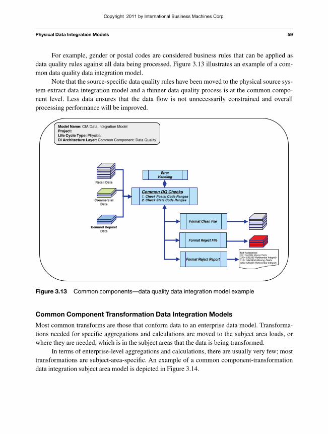
Figure 3.13 Common components—data quality data integration model example
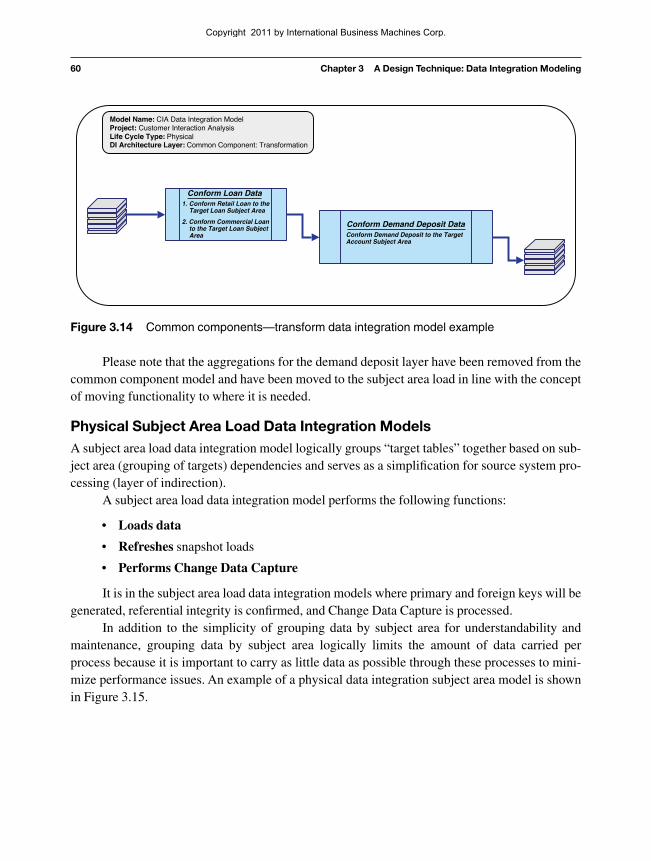
Common Component Transformation Data Integration Models
Most common transforms are those that conform data to an enterprise data model. Transforma-tions needed for specific aggregations and calculations are moved to the subject area loads, orwhere they are needed, which is in the subject areas that the data is being transformed.
In terms of enterprise-level aggregations and calculations, there are usually very few; mosttransformations are subject-area-specific. An example of a common component-transformationdata integration subject area model is depicted in Figure 3.14.
For example, gender or postal codes are considered business rules that can be applied asdata quality rules against all data being processed. Figure 3.13 illustrates an example of a com-mon data quality data integration model.
Note that the source-specific data quality rules have been moved to the physical source sys-tem extract data integration model and a thinner data quality process is at the common compo-nent level. Less data ensures that the data flow is not unnecessarily constrained and overallprocessing performance will be improved.
Copyright 2011 by International Business Machines Corp.
60 Chapter 3 A Design Technique: Data Integration Modeling
Please note that the aggregations for the demand deposit layer have been removed from thecommon component model and have been moved to the subject area load in line with the conceptof moving functionality to where it is needed.
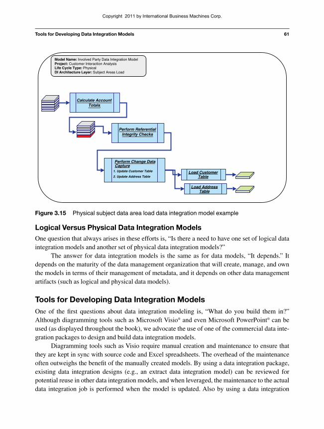
Physical Subject Area Load Data Integration ModelsA subject area load data integration model logically groups “target tables” together based on sub-ject area (grouping of targets) dependencies and serves as a simplification for source system pro-cessing (layer of indirection).
A subject area load data integration model performs the following functions:
• Loads data
• Refreshes snapshot loads
• Performs Change Data Capture
It is in the subject area load data integration models where primary and foreign keys will begenerated, referential integrity is confirmed, and Change Data Capture is processed.
In addition to the simplicity of grouping data by subject area for understandability andmaintenance, grouping data by subject area logically limits the amount of data carried perprocess because it is important to carry as little data as possible through these processes to mini-mize performance issues. An example of a physical data integration subject area model is shownin Figure 3.15.
Model Name: CIA Data Integration ModelProject: Customer Interaction AnalysisLife Cycle Type: PhysicalDI Architecture Layer: Common Component: Transformation
Conform Loan Data1. Conform Retail Loan to the
Target Loan Subject Area
2. Conform Commercial Loanto the Target Loan SubjectArea
Conform Demand Deposit DataConform Demand Deposit to the TargetAccount Subject Area
Figure 3.14 Common components—transform data integration model example
Copyright 2011 by International Business Machines Corp.
Tools for Developing Data Integration Models 61
Model Name: Involved Party Data Integration ModelProject: Customer Interaction AnalysisLife Cycle Type: PhysicalDI Architecture Layer: Subject Areas Load
Perform Change DataCapture
1. Update Customer Table
2. Update Address TableLoad Customer
Table
Load AddressTable
Calculate AccountTotals.
Perform ReferentialIntegrity Checks
Figure 3.15 Physical subject data area load data integration model example
Logical Versus Physical Data Integration ModelsOne question that always arises in these efforts is, “Is there a need to have one set of logical dataintegration models and another set of physical data integration models?”
The answer for data integration models is the same as for data models, “It depends.” Itdepends on the maturity of the data management organization that will create, manage, and ownthe models in terms of their management of metadata, and it depends on other data managementartifacts (such as logical and physical data models).
Tools for Developing Data Integration ModelsOne of the first questions about data integration modeling is, “What do you build them in?”Although diagramming tools such as Microsoft Visio® and even Microsoft PowerPoint® can beused (as displayed throughout the book), we advocate the use of one of the commercial data inte-gration packages to design and build data integration models.
Diagramming tools such as Visio require manual creation and maintenance to ensure thatthey are kept in sync with source code and Excel spreadsheets. The overhead of the maintenanceoften outweighs the benefit of the manually created models. By using a data integration package,existing data integration designs (e.g., an extract data integration model) can be reviewed forpotential reuse in other data integration models, and when leveraged, the maintenance to the actualdata integration job is performed when the model is updated. Also by using a data integration
Copyright 2011 by International Business Machines Corp.

62 Chapter 3 A Design Technique: Data Integration Modeling
Experience in using data integration packages for data integration modeling has shown thatdata integration projects and Centers of Excellence have seen the benefits of increased extract,transform and load code standardization, and quality. Key benefits from leveraging a data integra-tion package include the following:
• End-to-end communications—Using a data integration package facilitates fastertransfer of requirements from a data integration designer to a data integration developerby using the same common data integration metadata. Moving from a logical design to aphysical design using the same metadata in the same package speeds up the transferprocess and cuts down on transfer issues and errors. For example, source-to-target datadefinitions and mapping rules do not have to be transferred between technologies,
Ab Initio
IBM Data Stage
Informatica
Figure 3.16 Data integration models by technology
package such as Ab Initio, IBM Data Stage®, or Informatica to create data integration models, anorganization will further leverage the investment in technology it has.
Figure 3.16 provides examples of high-level logical data integration models built in Ab Ini-tio, IBM Data Stage, and Informatica.
Copyright 2011 by International Business Machines Corp.
Industry-Based Data Integration Models 63
thereby reducing mapping errors. This same benefit has been found in data modelingtools that transition from logical data models to physical data models.
• Development of leveragable enterprise models—Capturing data integration require-ments as logical and physical data integration models provides an organization anopportunity to combine these data integration models into enterprise data integrationmodels, which further matures the Information Management environment and increasesoverall reuse. It also provides the ability to reuse source extracts, target data loads, andcommon transformations that are in the data integration software package’s metadataengine. These physical data integration jobs are stored in the same metadata engine andcan be linked to each other. They can also be linked to other existing metadata objectssuch as logical data models and business functions.
• Capture of navigational metadata earlier in the process—By storing logical andphysical data integration model metadata in a data integration software package, anorganization is provided with the ability to perform a more thorough impact analysis ofa single source or target job. The capture of source-to-target mapping metadata withtransformation requirements earlier in the process also increases the probability ofcatching mapping errors in unit and systems testing. In addition, because metadata cap-ture is automated, it is more likely to be captured and managed.
Industry-Based Data Integration ModelsTo reduce risk and expedite design efforts in data warehousing projects, prebuilt data models fordata warehousing have been developed by IBM, Oracle, Microsoft, and Teradata.
As the concept of data integration modeling has matured, prebuilt data integration modelsare being developed in support of those industry data warehouse data models.
Prebuilt data integration models use the industry data warehouse models as the targets andknown commercial source systems for extracts. Having industry-based source systems and tar-gets, it is easy to develop data integration models with prebuilt source-to-target mappings. Forexample, in banking, there are common source systems, such as the following:
• Commercial and retail loan systems
• Demand deposit systems
• Enterprise resource systems such as SAP and Oracle
These known applications can be premapped to the industry-based data warehouse datamodels. Based on actual project experience, the use of industry-based data integration modelscan significantly cut the time and cost of a data integration project. An example of an industry-based data integration model is illustrated in Figure 3.17.
Copyright 2011 by International Business Machines Corp.

64 Chapter 3 A Design Technique: Data Integration Modeling
In the preceding example, the industry data integration model provides the following:
• Prebuilt extract processes from the customer, retail loan, and commercial loan systems
• Prebuilt data quality processes based on known data quality requirements in the targetdata model
• Prebuilt load processes based on the target data model subject areas
Starting with existing designs based on a known data integration architecture, source sys-tems, and target data models, provides a framework for accelerating the development of a dataintegration application.
SummaryData modeling is a graphical design technique for data. In data integration, data integration mod-eling is a technique for designing data integration processes using a graphical process modelingtechnique against the data integration reference architecture.
This chapter detailed the types of data integration models—conceptual, logical, and physical—and the approach for subdividing the models based on the process layers of the dataintegration reference architecture. This chapter also provided examples of each of the differentlogical and physical data integration model types.
It covered the transition from logical data integration models to physical data integrationmodels, which might be better stated as how to move from the “whats” to the “hows.”
Finally, the chapter discussed how this maturing technique can be used to create prebuilt,industry-based data integration models.
The next chapter is a case study for a bank that is building a set of data integrationprocesses and uses data integration modeling to design the planned data integration jobs.
PrebuiltData Quality
Model PrebuiltTransform
Model
Bad Transactions0101 3443434 Missing Fields0304 535355 Referential Integrity0101 3443434 Missing Fields0304 535355 Referential Integrity
Bus DQCheck
Tech DQChecks
ErrorHandling
ConformLoanData
PrebuiltCustomer Source
System Model
PrebuiltRetail Loan Source
System Model
PrebuiltCommercial Loan
Source SystemModel
LoanSubject Area Load
Model
LoanSubject Area Load
Model
Figure 3.17 Industry-based data integration model example
Copyright 2011 by International Business Machines Corp.
End-of-Chapter QuestionsQuestion 1.Data integration modeling is based on what other modeling paradigm?Question 2.List and describe the types of logical data integration models.Question 3.List and describe the types of physical data integration models.Question 4.Using the target-based design technique, document where the logical data quality logic is movedto and why in the physical data integration model layers.Question 5.Using the target-based design technique, document where the logical transformation logic ismoved to and why in the physical data integration model layers.
End-of-Chapter Questions 65
Copyright 2011 by International Business Machines Corp.