Embed Size (px)
Citation preview
1
A Detailed Electronic Mechanism
for Sudden Unintended Acceleration
R. Belt
2 August 2012
A Detailed Electronic Mechanism
for Sudden Unintended Acceleration
by
Ronald A. Belt
Plymouth, MN 55447
2 August 2012
Abstract: An electronic cause for sudden unintended acceleration was discussed in a previous paper. The cause was attributed to a negative voltage spike on the battery supply line leading to a brownout error that causes faulty
operation of the CPUs, keep-alive memory, and/or EEPROM memory, resulting in a data error that causes
unpredictable engine operation, such as sudden acceleration. While this cause explained many observations
associated with sudden acceleration, the theory was incomplete because it never identified the precise hardware or
software fault producing the data error. In this paper a mechanism for this data error is presented. The mechanism
involves a sudden change in the correction value that is used to adjust the PWM duty cycle applied to the throttle
motor to compensate for variations in the battery voltage. The evidence for and against this mechanism is discussed.
I. Introduction
A previous paper by this author discussed an electronic cause for sudden unintended acceleration.1 The paper
concluded that the following electronic cause was involved:
At idle, when the alternator cannot supply all the current required by the vehicle’s electrical
system, and the battery must supply the additional current, the system voltage is determined by the
battery voltage. In this case, if the battery charge is weak (i.e., the battery becomes “run down”),
then the battery voltage will be low, and the inrush current caused by one of the vehicle’s
electrical functions (e.g., an electric motor) starting up will cause a large negative voltage spike on the battery supply line that passes through the ECM voltage regulators and leads to a brownout
error in the CPUs, if the CPUs are not properly held in reset by the ECM voltage supply. The
brownout error can cause faulty operation of the CPUs, keep-alive memory, and/or EEPROM
memory, leading to a data error that causes unpredictable engine behavior, such as sudden
acceleration.
While this cause explained many of the observations associated with sudden acceleration, the theory was incomplete
because it never identified the precise hardware or software fault producing the data error. Therefore, a search for a
specific mechanism capable of producing a data error was undertaken.
The following observations guided the search for a detailed mechanism:
1. Assuming the results of the previous paper, the fault must be produced by a negative-going spike on the battery supply line that somehow changes a data value, which leads to higher engine RPM’s.
2. The sudden unintended incidence rate is higher for vehicles with electronic throttles. For Toyotas this
implies that the fault must lie within the ETCS-i system.
3. The high RPM’s, and therefore the incorrect data value, can persist as long as the ignition is left on.
4. Turning the ignition off and then back on again usually restores the engine RPM’s back to normal.
Therefore, the incorrect data value must be replaced by a new value when the ignition is turned on.
5. Many incidents have occurred when the transmission was shifted from PARK into either DRIVE or
REVERSE. This could mean either that SUI does not occur in PARK, or that it is initiated by shifting out
of PARK.
6. Higher RPM’s persist when the vehicle is shifted from DRIVE into NEUTRAL. This makes it more likely
that higher RPM’s also occur in PARK, resulting in 5) implying that SUI is initiated by shifting out of PARK.
Observation 2) implies that the root cause lies somewhere within the functional diagram of an electronic throttle
system as shown in Figure 1. NASA studied all the functions in this diagram for Toyota’s ETCS-i system and

2
A Detailed Electronic Mechanism
for Sudden Unintended Acceleration
R. Belt
2 August 2012
concluded that they could find no electronic cause for sudden acceleration. In spite of this conclusion, the author
decided to review the NASA report once more with an eye open for faults that could be produced by negative-going
voltage spikes on the battery power supply as suggested by observation 1) above. This review involved not only a
careful analysis of all test results to check for any possible omissions or incomplete verifications of performance, but
also a careful reading of all the redacted portions of the report to look for anything that might relate to observations
1) through 6) above. Although some of the redactions in the report had been removed in a second release of the report dated 15 April 2011, there were still substantial portions of the report that remained redacted. Some of these
remaining redactions were read by copying and pasting the redacted portions into a Microsoft Word document2.
Fig 1. Electronic throttle system functional diagram taken from the NASA final report3
While reading the redacted portions of the NASA report, the author found an interesting statement on page 93 of the
software document, Appendix A, which immediately caught his attention. Figure 2 shows this page with the
statement highlighted.
Fig 2. Page 93 of the NASA final report,
Appendix A – Software4

3
A Detailed Electronic Mechanism
for Sudden Unintended Acceleration
R. Belt
2 August 2012
The statement reads:
A.11.3.4.8 Duty-Cycle Conversion The duty cycle conversion modifies scales the command based on the battery voltage and converts the signal to a duty cycle percentage. The duty cycle conversion operates at a rate of 16ms.
At first glance, this statement seems innocent enough given that the PID controller output must be converted into a
duty cycle in order to control the throttle motor. However, the reference to “scaling the command based on battery
voltage” immediately raises a red flag. This means that the PID output is multiplied by a constant which, if its value
is incorrect, can cause the throttle to increase or decrease suddenly without an input from the driver. This constant
is determined from a sensor output (voltage sensor) that is not redundant and that might have negative voltage spikes
on it according to the author’s previous paper. Moreover, the multiplication operation occurs at a point in the system where it constitutes a single point of failure, has no diagnostics associated with it, and has no fail-safe mode
identified. This operation required a closer look to understand its purpose and to see if it can produce sudden
acceleration.
II. Duty Cycle Voltage Compensation
Purpose of Duty Cycle Voltage Compensation. Figure 3 shows a more detailed block diagram of the functions in an
electronic throttle system. The throttle motor operates against the force of a spring which pulls it back to the limp
home position when power to the motor is turned off. The throttle motor is a permanent magnet DC motor with brushes that is powered by battery current applied through an H-bridge. The battery current is turned on and off
(i.e., modulated) by the PWM controller, which controls the duty cycle of the current through the motor. A higher
duty cycle produces a larger motor torque, causing the throttle motor to open the throttle further and produce a
higher engine speed. The motor torque is proportional to the motor current, which is given by I = VBATT/Rmot, where
VBATT is the applied voltage and Rmot is the motor resistance. The motor speed is proportional to the applied
voltage, VBATT. The motor power P is given by P = IV = VBATT2/Rmot. Therefore, the throttle motor power varies
with the square of the battery voltage. The throttle motor power determines how fast the throttle will open in
response to the driver’s command. This means the throttle will open more slowly at lower battery voltages because
there is less power to oppose the return spring. This has the undesirable effect of causing the engine to lag under
acceleration when the battery voltage is low. To prevent this change in accelerator response from occurring, the
output of the PID controller is multiplied by a constant KM = (14.4V/VBATT)2, which cancels out the battery voltage
dependence by normalizing the throttle motor current to a constant 14.4 volts. Figure 4 shows that this duty cycle correction factor can vary from 1 at a battery voltage of 14.4V to as much as 3.2 at a battery voltage of 8.0V.
Fig 3. Detailed block diagram of the throttle motor control loop showing the battery voltage correction function.

4
A Detailed Electronic Mechanism
for Sudden Unintended Acceleration
R. Belt
2 August 2012
When the PID controller output is multiplied by this correction factor to modify the PWM duty cycle, one is
essentially increasing the gain of the coefficients in the PID controller, which normally changes the stability of the
control loop. However, since the throttle motor has an opposite voltage dependence, the motor gain decreases by the
same ratio, causing the two gain changes to cancel, leaving the loop gain constant. Therefore, there should be no
change in the loop gain as the battery voltage changes. There is also no change in the loop phase margin due to
changes in the battery voltage. This is the way the function is designed to work. More will be said about this later.
Fig 4. Example duty correction calculated using
the formula shown (normalized to 1 at 14.4V).
Fig 5. Injector dead time for a Buick Regal obtained
via look-up table (normalized to 1 for 14.4V)
Incidentally, a similar battery voltage correction is made to the injector “on” times, which control the amount of fuel squirted into the cylinders during each combustion cycle. This is because the fuel pressure and the time it takes
before an injector opens also depend on the battery voltage, and also are reduced as the battery voltage is lowered.
However, in this case the battery voltage correction is an additive value which is added to the injector “on” time.
This value is shown in Figure 5. It does not have a simple dependence on battery voltage, so it is usually measured
and then put into a look-up table from which it is obtained by the CPU during engine operation.
Duty Cycle Voltage Correction with Spikes on the Battery Supply Line. Let’s now look at what happens to the duty
cycle voltage correction process when a negative voltage spike is encountered on the battery supply line. This case
is shown in Figure 6. The negative voltage spike very quickly affects the throttle motor and lowers its gain due to
the lower battery voltage seen by the throttle motor, as shown by the blue line in Fig 6. The same spike is also
digitized by the sub-CPU at some random point on the spike because the spike is not synchronous with the A/D conversion interval, as shown by the red line in Fig 6.
Fig 6. Conceptual diagram showing how a delay in applying the battery
correction value can cause the PID gain increase to exceed the throttle motor
gain decrease causing the PID controller to increase the throttle setting5
5
A Detailed Electronic Mechanism
for Sudden Unintended Acceleration
R. Belt
2 August 2012
The digitized spike voltage is then converted into a gain correction value that is used to increase the gain of the PID
controller, which produces an increase in the PWM duty cycle by the same gain factor. If there is no delay in
calculating the duty cycle correction value, then the duty cycle increase applied to the motor coincides with the
battery voltage decrease at the motor, and the two gain changes cancel, leaving the motor torque unchanged. This
corresponds to the two curves in Fig 6 being superimposed on one another. However, if there is any delay in calculating the duty cycle correction value, then the two gain changes will not coincide, producing a decrease in the
throttle motor gain followed by an increase in the PID controller gain as shown by the two oppositely shaded areas
in Fig 6. This is equivalent to a net decrease in the control loop gain followed by a net increase in the control loop
gain, which can amount to a factor of three gain change in each direction as we saw in Fig 4. This will produce a
sudden decrease in throttle motor torque followed by a sudden increase in torque, which corresponds to a sudden
increase in engine RPM. Large voltage spikes will produce large duty cycle correction values that, if they are not
coincident with the drop in motor gain, can lead to large increases in engine RPM as found in some sudden
acceleration incidents. Smaller voltage spikes will produce smaller duty cycle correction values that, if they are not
coincident with the drop in motor gain, can lead to smaller increases in engine RPM as found in most other sudden
acceleration incidents. If a large voltage spike causes the throttle increase to exceed about 88% of full throttle, then
there is a chance that the throttle will stay above 88%, leading to a long term sudden acceleration incident. Smaller
voltage spikes produce less of a throttle increase which may last only a short time. These are frequently interpreted as surging or lunging incidents.
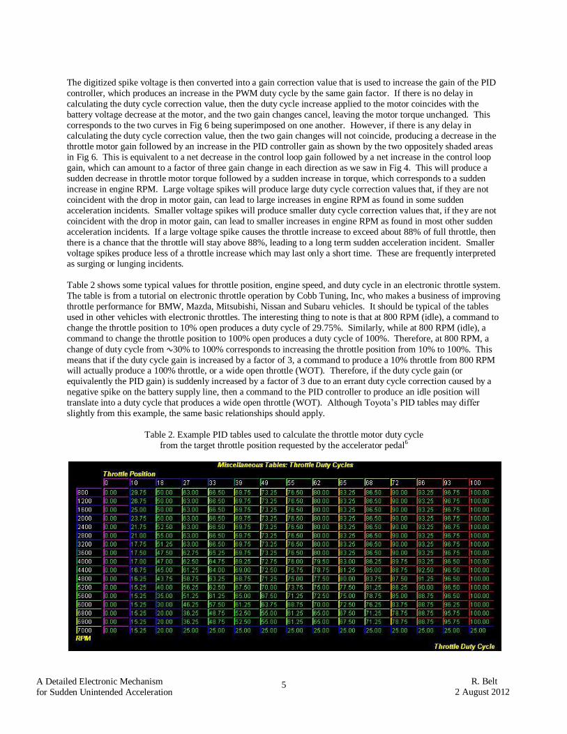
Table 2 shows some typical values for throttle position, engine speed, and duty cycle in an electronic throttle system.
The table is from a tutorial on electronic throttle operation by Cobb Tuning, Inc, who makes a business of improving
throttle performance for BMW, Mazda, Mitsubishi, Nissan and Subaru vehicles. It should be typical of the tables
used in other vehicles with electronic throttles. The interesting thing to note is that at 800 RPM (idle), a command to
change the throttle position to 10% open produces a duty cycle of 29.75%. Similarly, while at 800 RPM (idle), a
command to change the throttle position to 100% open produces a duty cycle of 100%. Therefore, at 800 RPM, a
change of duty cycle from ∿30% to 100% corresponds to increasing the throttle position from 10% to 100%. This
means that if the duty cycle gain is increased by a factor of 3, a command to produce a 10% throttle from 800 RPM will actually produce a 100% throttle, or a wide open throttle (WOT). Therefore, if the duty cycle gain (or
equivalently the PID gain) is suddenly increased by a factor of 3 due to an errant duty cycle correction caused by a
negative spike on the battery supply line, then a command to the PID controller to produce an idle position will
translate into a duty cycle that produces a wide open throttle (WOT). Although Toyota’s PID tables may differ
slightly from this example, the same basic relationships should apply.
Table 2. Example PID tables used to calculate the throttle motor duty cycle
from the target throttle position requested by the accelerator pedal6
6
A Detailed Electronic Mechanism
for Sudden Unintended Acceleration
R. Belt
2 August 2012
Origin of the Delay Causing Lack of Coincidence. We will now look at how a delay between the positive and
negative gain changes can arise to cause them to be non-coincident at the throttle motor. This requires looking at the
algorithm structure used to compute the duty cycle correction value within the main CPU of the ECM. This is
difficult to do with certainty because we don’t have access to the software in the ECM CPU’s. However, we can
make some reasonable assumptions about these operations because there aren’t many different ways to do them.
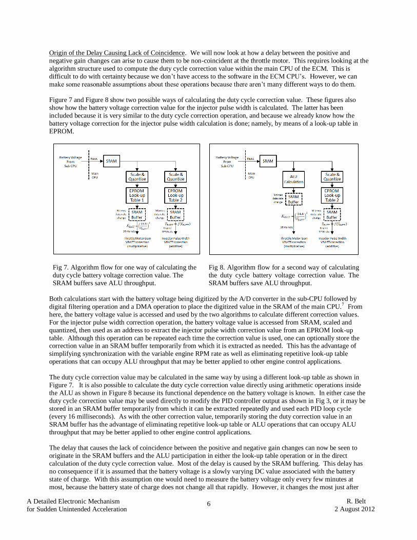
Figure 7 and Figure 8 show two possible ways of calculating the duty cycle correction value. These figures also
show how the battery voltage correction value for the injector pulse width is calculated. The latter has been
included because it is very similar to the duty cycle correction operation, and because we already know how the
battery voltage correction for the injector pulse width calculation is done; namely, by means of a look-up table in
EPROM.
Fig 7. Algorithm flow for one way of calculating the
duty cycle battery voltage correction value. The
SRAM buffers save ALU throughput.
Fig 8. Algorithm flow for a second way of calculating
the duty cycle battery voltage correction value. The
SRAM buffers save ALU throughput.
Both calculations start with the battery voltage being digitized by the A/D converter in the sub-CPU followed by
digital filtering operation and a DMA operation to place the digitized value in the SRAM of the main CPU.7 From
here, the battery voltage value is accessed and used by the two algorithms to calculate different correction values.
For the injector pulse width correction operation, the battery voltage value is accessed from SRAM, scaled and
quantized, then used as an address to extract the injector pulse width correction value from an EPROM look-up
table. Although this operation can be repeated each time the correction value is used, one can optionally store the correction value in an SRAM buffer temporarily from which it is extracted as needed. This has the advantage of
simplifying synchronization with the variable engine RPM rate as well as eliminating repetitive look-up table
operations that can occupy ALU throughput that may be better applied to other engine control applications.
The duty cycle correction value may be calculated in the same way by using a different look-up table as shown in
Figure 7. It is also possible to calculate the duty cycle correction value directly using arithmetic operations inside
the ALU as shown in Figure 8 because its functional dependence on the battery voltage is known. In either case the
duty cycle correction value may be used directly to modify the PID controller output as shown in Fig 3, or it may be
stored in an SRAM buffer temporarily from which it can be extracted repeatedly and used each PID loop cycle
(every 16 milliseconds). As with the other correction value, temporarily storing the duty correction value in an
SRAM buffer has the advantage of eliminating repetitive look-up table or ALU operations that can occupy ALU
throughput that may be better applied to other engine control applications.
The delay that causes the lack of coincidence between the positive and negative gain changes can now be seen to
originate in the SRAM buffers and the ALU participation in either the look-up table operation or in the direct
calculation of the duty cycle correction value. Most of the delay is caused by the SRAM buffering. This delay has
no consequence if it is assumed that the battery voltage is a slowly varying DC value associated with the battery
state of charge. With this assumption one would need to measure the battery voltage only every few minutes at
most, because the battery state of charge does not change all that rapidly. However, it changes the most just after
7
A Detailed Electronic Mechanism
for Sudden Unintended Acceleration
R. Belt
2 August 2012
starting the engine because the starter draws hundreds of amps of current. Therefore, it makes sense to correct for
the battery voltage immediately after engine starting, and from then on only every few minutes, such as when the
engine is at idle. It appears that the auto manufacturers have made this assumption. This is a good assumption if
one has absolute confidence that the digital filtering operation in the sub-CPU removes all voltage spikes from the
digitized battery voltage, leaving the correct DC value. But if an occasional voltage spike somehow makes it
through, or if an error occurs in the transfer from the sub CPU to the main CPU or in one of the SRAM’s, then the duty cycle correction value will be delayed by the SRAM operations for many seconds, and there will be a lack of
coincidence between the corrected duty cycle and the original voltage reduction at the motor due to the same voltage
spike. This may cause a sudden acceleration, surge, or lurch, depending on the magnitude of the voltage spike and
the value of the subsequent duty cycle voltage correction.
Another possible origin for a delay in the duty cycle correction value is reset of the CPU’s due to a voltage spike on
the battery supply line after a voltage sample has been taken.
Duration of Sudden Acceleration Events. The temporary storage of data in an SRAM buffer discussed in the
previous section also explains the duration of sudden acceleration events. As long as the errant duty cycle correction
value remains unchanged, the increase in PID gain created by a voltage spike will cause the PWM controller to
produce a higher duty cycle command to the throttle motor, thereby increasing its output torque and producing a higher engine RPM. This increase in RPM may persist for many minutes until a duty cycle correction value is
calculated from a new battery voltage sample. This explains observation 3) in Section I of this paper. And the
increase in RPM will be removed by turning off the ignition and restarting the vehicle because a new duty cycle
correction value is calculated each time the engine is started, since the battery voltage is sampled immediately after
starting. This explains observation 4) in the Section I of this paper.
Robustness of the Filtering Operation. It is difficult to construct a perfect filter that will remove all the voltage
spikes from the battery supply line to yield the DC value of the voltage. This is discussed in Denso patent number
6933897 and in related patents by other auto manufacturers.8 The problem is that one must look at other voltage
samples next to the sample of interest to make a judgment about whether the sample is a spike or not. The more
samples that are used, the better the spike elimination, but the longer the time it takes to process the additional samples. This additional time is limited in a CPU that must also devote precious resources to controlling the
injection time, the ignition timing, the valve timing, and transmission shifting, in addition to the throttle control and
maintaining a watch on all sensor inputs. The problem is similar to removing voltage spikes from the throttle sensor
output before being used by the PID controller, which is a problem that has existed in all fuel injection engines since
the early 1990’s. The solution involves a compromise between spike rejection performance and ALU throughput,
which means that some spikes may make it through. Given the variation in spike amplitudes, decay times, and
duration that exist on a vehicle due to the normal and abnormal operation of its electrical functions, there is little
wonder why this filtering operation might not be perfect.
Other Potential Causes of Duty Cycle Correction Errors. The mechanism discussed in the previous paragraphs
requires no hardware or software faults to produce sudden acceleration other than the imperfect operation of the
voltage smoothing filter. However, hardware faults can also lead to errors in the duty cycle correction value that might add to the incident rate. Such hardware faults include:
1. Errors in the DMA transfer of the digital voltage values between the sub-CPU and the main CPU. The
possibility of such transfer errors is discussed in Denso patent number 8131455, in which a scheme for
reducing these errors is proposed.9 Clearly, then, such errors are a distinct possibility.
2. Errors caused by upset of the data stored in SRAM. This can occur to either the battery voltage values
stored in SRAM as a result of the DMA operation, or to the duty cycle correction values stored in a
buffer SRAM after their calculation. In this case, the SRAM is the on-chip SRAM in the main CPU,
which is powered by 2.5V supplied by a linear regulator on the power supply ASIC. This voltage can
have negative spikes on it which pass through the regulator from the 12V supply via the 6V SMPS
regulator, which might cause upset of the data, particularly during an SRAM writing operation. In
more recent CPU chips, this SRAM supply voltage is as low as 1.7V, meaning that the margin for upset is even less. And if the values are stored in the keep-alive portion of the same SRAM, then a
different linear regulator is used that is powered directly from the 12V supply, making upsets even
more likely. This different regulator is not monitored by the watchdog processor in the power supply
ASIC.
8
A Detailed Electronic Mechanism
for Sudden Unintended Acceleration
R. Belt
2 August 2012
3. Errors in the CPU operation. Errors in the CPU operation might arise because the CPU runs slower at
lower bias voltages, making it more difficult to meet control loops having tight timing margins.
In each of these cases, an error in the duty cycle correction value is produced in the same way that it is produced by
an imperfect voltage smoothing filter, and the same effects on throttle operation can result.
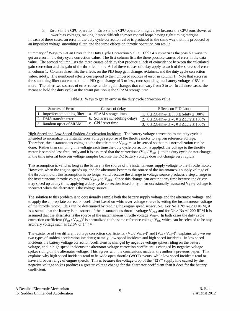
Summary of Ways to Get an Error in the Duty Cycle Correction Value. Table 4 summarizes the possible ways to get an error in the duty cycle correction value. The first column lists the three possible causes of error in the data
value. The second column lists the three causes of delay that produce a lack of coincidence between the calculated
gain correction and the gain of the throttle motor. All of these causes of delay apply to each of the sources of error
in column 1. Column three lists the effects on the PID loop gain change, GainPID, and the duty cycle correction
value, duty. The numbered effects correspond to the numbered sources of error in column 1. Note that errors in the smoothing filter cause a maximum PID gain change of 3 or less, corresponding to a battery voltage of 8V or
more. The other two sources of error cause random gain changes that can vary from 0 to . In all three cases, the means to hold the duty cycle at the errant position is the SRAM storage time.
Table 3. Ways to get an error in the duty cycle correction value
Sources of Error Causes of delay Effects on PID Loop
1. Imperfect smoothing filter a. SRAM storage times
b. Software scheduling delays
c. CPU reset time
1. 0 ≤ GainPID ≤ 3, 0 ≤ duty ≤ 100%
2. DMA transfer error 2. 0 ≤ GainPID ≤ , 0 ≤ duty ≤ 100%
3. Random upset of SRAM 3. 0 ≤ GainPID ≤ , 0 ≤ duty ≤ 100%
High Speed and Low Speed Sudden Acceleration Incidents. The battery voltage correction to the duty cycle is
intended to normalize the instantaneous voltage response of the throttle motor to a given reference voltage.
Therefore, the instantaneous voltage to the throttle motor VINST must be sensed so that this normalization can be
done. Rather than sampling this voltage each time the duty cycle correction is applied, the voltage to the throttle motor is sampled less frequently and it is assumed that the corrections (Vref / VINST)2 to the duty cycle do not change
in the time interval between voltage samples because the DC battery voltage does not change very rapidly.
This assumption is valid as long as the battery is the source of the instantaneous supply voltage to the throttle motor.
However, when the engine speeds up, and the alternator becomes the source of the instantaneous supply voltage of
the throttle motor, this assumption is no longer valid because the change in voltage source produces a step change in
the instantaneous throttle voltage from VBATT to VALT. Since this change can occur at any time because the driver
may speed up at any time, applying a duty cycle correction based only on an occasionally measured VBATT voltage is
incorrect when the alternator is the voltage source.
The solution to this problem is to occasionally sample both the battery supply voltage and the alternator voltage, and to apply the appropriate correction coefficient based on whichever voltage source is setting the instantaneous voltage
of the throttle motor. This can be determined by reading the engine speed sensor, Ne. For Ne < Nx ∿1200 RPM, it
is assumed that the battery is the source of the instantaneous throttle voltage VINST and for Ne > Nx ∿1200 RPM it is
assumed that the alternator is the source of the instantaneous throttle voltage VINST. In both cases the duty cycle
correction coefficient (Vref / VINST)2 is normalized to the same reference voltage Vref, which can be selected to be any
arbitrary voltage such as 12.6V or 14.4V.
The existence of two different voltage correction coefficients, (Vref / VBATT)2 and (Vref / VALT)2, explains why we see
two types of sudden acceleration incidents; namely, low speed incidents and high speed incidents. In low speed
incidents the battery voltage correction coefficient is changed by negative voltage spikes riding on the battery voltage, and in high speed incidents the alternator voltage correction coefficient is changed by negative voltage
spikes riding on the alternator voltage. This agrees with the conclusions made in the author’s previous paper. This
explains why high speed incidents tend to be wide open throttle (WOT) events, while low speed incidents tend to
have a broader range of engine speeds. This is because the voltage drop of the “12V” supply line caused by the
negative voltage spikes produces a greater voltage change for the alternator coefficient than it does for the battery
coefficient.
9
A Detailed Electronic Mechanism
for Sudden Unintended Acceleration
R. Belt
2 August 2012
Injector Voltage Correction Errors. Since the injector voltage correction operation and the throttle motor voltage
correction operation both use the same measured battery voltage, an incorrect value of the battery voltage caused by
sampling during a negative voltage spike can produce an incorrect injector output. In this case, a lower battery
voltage will produce a larger injector correction value, causing a larger amount of fuel to be injected into the engine.
This means that the same negative voltage spike that increases the throttle opening, causing more air to be fed into
the engine, will also increase the injector duration, causing more fuel to be fed into the engine as well. This explains why the engine torque is so strong during a sudden acceleration event, which is seen sometimes in the tire marks
produced by the drive wheels when accelerating suddenly from a stationary position.
Even in vehicles without electronic throttles, a sudden increase in the injector on-time duration that is not
commanded by the driver can be a cause of sudden acceleration. This has been noted by Continental Automotive
Gmbh in US patent 8108124, where it states:
“Should there be a fault in the system that increases the amount [of fuel] injected such as for example a jamming injector and/or a rail pressure sensor giving false measurements, then the increase in the amount of
fuel is not detected. In this case, the generated torque does not correspond to the wish of the driver and the vehicle may, unintended by the driver, accelerate. In the worst case, it may lead to a “runaway” meaning the uncontrolled acceleration of the internal combustion engine, which can lead to its destruction.”10
Therefore, a fault caused by a negative voltage spike producing a larger than required injector voltage correction
coefficient can cause sudden acceleration. This explains the existence of sudden acceleration in vehicles with fuel
injected engines even without electronic throttles.
It is interesting that two different correction coefficients are also needed for the injector voltage correction value.
The reason is the same as for the throttle motor duty cycle voltage correction value; namely that the instantaneous injector voltage can change at any time from the battery-determined value to the alternator-determined value. The
only difference from the throttle motor correction is in the expression used to calculate the two correction
coefficients. No auto manufacturer has ever pointed out the necessity of having two correction coefficients for the
battery voltage compensation of fuel injection on-time since fuel injection engines have been on the market.
III. Evidence For and Against Duty Cycle Compensation
We will now discuss the evidence for and against duty cycle compensation as a root cause of sudden unintended
acceleration. This evidence is summarized in Table 4.
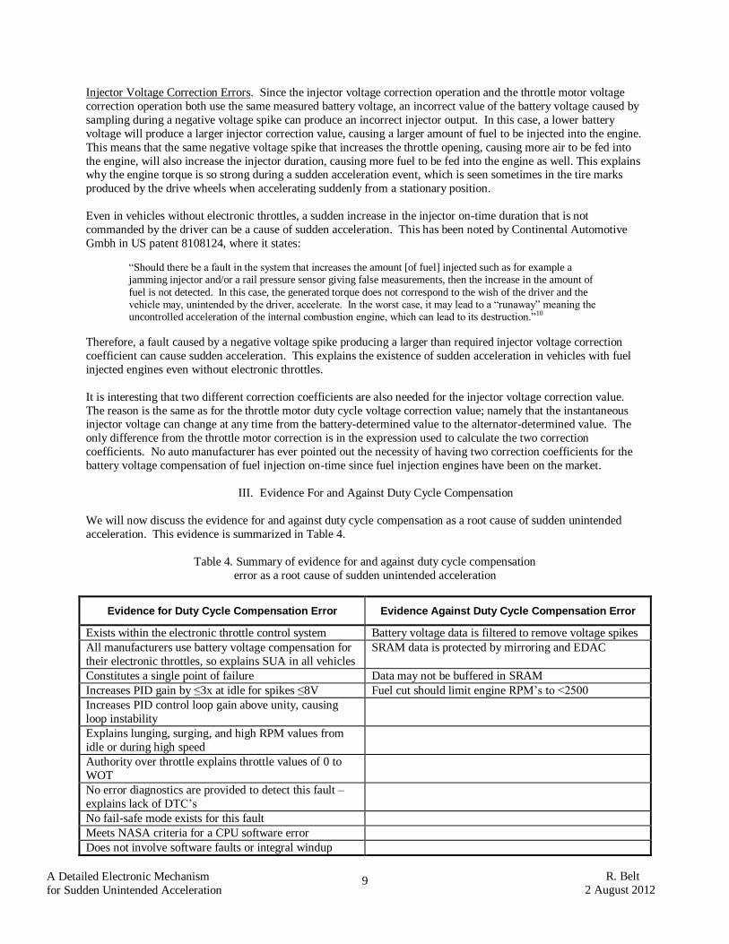
Table 4. Summary of evidence for and against duty cycle compensation
error as a root cause of sudden unintended acceleration
Evidence for Duty Cycle Compensation Error Evidence Against Duty Cycle Compensation Error
Exists within the electronic throttle control system Battery voltage data is filtered to remove voltage spikes
All manufacturers use battery voltage compensation for
their electronic throttles, so explains SUA in all vehicles
SRAM data is protected by mirroring and EDAC
Constitutes a single point of failure Data may not be buffered in SRAM
Increases PID gain by ≤3x at idle for spikes ≤8V Fuel cut should limit engine RPM’s to <2500
Increases PID control loop gain above unity, causing
loop instability
Explains lunging, surging, and high RPM values from
idle or during high speed
Authority over throttle explains throttle values of 0 to
WOT
No error diagnostics are provided to detect this fault –
explains lack of DTC’s
No fail-safe mode exists for this fault
Meets NASA criteria for a CPU software error
Does not involve software faults or integral windup

10
A Detailed Electronic Mechanism
for Sudden Unintended Acceleration
R. Belt
2 August 2012
and maybe not hardware faults
Explains existence of high speed and low speed SUA
incidents
Evidence for Duty Cycle Compensation.
1. Exists within the electronic throttle control system. Compensation of the duty cycle for battery voltage changes
is a necessary operation for all electronic throttle systems because battery voltage changes can cause the throttle
motor to have less torque at lower voltages, which reduces the engine RPM for a given accelerator position. This
affects the vehicle drivability, because the driver must adjust by pressing harder on the accelerator when the
battery voltage is lower. At very low battery voltages the engine RPM range is limited, which affects vehicle
speed and acceleration. This function explains why Toyota models with ETCS-i have a higher sudden
acceleration incident rate than Toyota models without ETCS-i.
2. All auto manufacturers use battery voltage compensation in their electronic throttle systems. This explains why
all manufacturers’ vehicles have at least some susceptibility to sudden acceleration. The variations in
susceptibility among auto manufacturers may be attributed to differences in electrical system design which
affects the chances of producing voltage spikes and to differences in smoothing filters for removing spikes from
the battery voltage data.
3. Constitutes a single point of failure. Fig 3 shows that the output of the PID controller is a single amplitude value
which gets converted into a PWM duty cycle that is used to control the on-time of the transistors in an H-bridge,
which thereby control the duty cycle of the current in the throttle motor. Therefore, the single amplitude value
produced by the PID controller is a single point of failure that can produce a throttle opening fault as a result of
just one error in amplitude value. There is no need to have multiple faults, as is necessary with tin whiskers causing errors in the accelerator pedal sensor.
4. Increases PID gain by ≤3x at idle for spikes ≤8V. Fig 4 shows that the battery voltage correction factor is 3.2 at
a battery voltage of 8V. This means that the PID gain can be multiplied by 3.2x for voltage spikes as low as 8V.
If there is a lack of coincidence between the increase in PID gain and the decrease in throttle motor gain, then
there will be a net increase in the PID loop gain by a factor of 3.2x. Voltage spikes between 12.6V and 8.0V will
produce smaller increases in PID gain.
5. Increases PID control loop gain above unity, causing loop instability. The PID gain is one component of the
PID control loop, which includes the throttle motor and the throttle position sensor. This control loop is a
negative feedback control loop, which must have a total gain of less than one or else the control loop will become unstable. If the PID gain is increased without the throttle motor undergoing a corresponding decrease,
then the total loop gain will increase, possibly to greater than unity. When this happens, the control loop
becomes unstable, and the control command to the throttle motor can go to the maximum value, or wide open
throttle, causing sudden acceleration.
6. Explains lunging, surging, and high RPM values from idle or during high speed. Table 2 shows that a PID gain
increase of 3.2x can move the throttle from the idle position to wide open throttle (WOT). This means that the
vehicle’s control system thinks that the engine is at idle, but the engine is really at a higher throttle position
because the errant gain correction value has increased the PID loop gain from its normal value. A large PID loop
gain increase caused by a large voltage spike dropping the battery voltage down to around 8V will cause large
engine RPM’s increases un-commanded by the driver that are associated with wide open throttle (WOT) sudden
acceleration events from a stop or at high speed. A smaller PID loop gain increase caused by voltage spikes dropping the battery voltage to somewhere between 12.6V and 8.0V will produce smaller engine RPM increases
un-commanded by the driver that produce lunging and surging events. Therefore, an entire spectrum of engine
RPM increases is explained by the spectrum of voltage spike amplitudes.
7. Authority over throttle explains throttle values of 0 to WOT. This is just an automobile engineer’s way of saying
what was said previously in 5) above. A duty cycle correction increase that is not balanced by a throttle motor
gain decrease has the authority to produce a throttle increase from idle to wide open throttle (WOT), without any
input from the driver. This is similar in scope to the authority that the driver himself has over the throttle. This

11
A Detailed Electronic Mechanism
for Sudden Unintended Acceleration
R. Belt
2 August 2012
cannot be considered safe system design practice to allow such a wide authority over the throttle without an input
from the driver. Note that this is not just a Toyota problem, but a problem for all auto manufacturers using an
electronic throttle system.
8. No error diagnostics are provided to detect this fault. The battery voltage can be considered to be a sensor input
to an electronic throttle system in the same way that the accelerator pedal position (APP) sensor and the throttle position sensor (TPS) are sensor inputs. Table 5 summarizes these sensor inputs. The NASA report discusses no
error diagnostics associated with the voltage sensor or with the duty cycle correction process. In fact, it may be
impossible to include such error diagnostics because they would produce delays that might upset the stability of
the PID control loop. The lack of error diagnostics for this sensor and its data explains the lack of diagnostic
trouble codes (DTC’s) that exists following a sudden acceleration incident. The closest DTC that might apply is
a DTC for low battery voltage. And this pending DTC gets canceled when a new battery voltage is sampled
after restarting the engine if the battery is healthy and the battery voltage sensor does not detect a negative
voltage spike.
Table 5. Comparison of three sensors and their resulting learned values
Accelerator Pedal
Zero Reference
Throttle Sensor
Zero Reference
PWM Duty
Battery Voltage
Correction
Redundancy Two APP sensors Two TSP sensors One VBATT sensor
Learned value 2 VPA0’s for fully
released pedal position
2 VTAdet’s for
limp home position
1 duty correction at
arbitrary VBATT
Default values VPA1 = 20°
VPA2 = 55°
VTA1 = 0.095V
at détente (6.5° open) duty = 1
at VBATT = 14.4V
When learned SPD<3 km/h after >15
VPA<0.2V after >0.4V
STP = ON
D = ? VPA stable>2 sec
VPA0<0.0388V
20 to 60 ms
after IGN on
After engine start and ?
thereafter
Update interval When accel pedal released2
1 time/ignition cycle minutes ?
Change allowed VPA0<0.01952V VTA<1°/ignition cycle V = 14.4V to 8V
Storage location KAM KAM KAM
Memory protection Data mirroring
Method A
+EDAC?
Data mirroring
Method B
+EDAC?
Data mirroring
Method B
+EDAC?
Change needed for SUA
Larger VPA
Smaller VPA0
Smaller VTA Larger VTAdet
Larger PWM duty Smaller VBATT
Maximum change
allowed
? ? 0 ≤ duty ≤ 100%
for V 14.4Vto 8V
Error diagnostics Yes Yes None
Fail-safe modes Yes (Table 6) Yes (Table 6) None
Other fail safe modes Idle on fuel cut Idle on fuel cut Idle on fuel cut
9. No fail-safe mode exists for this fault. Table 6 from the NASA report shows all fail-safe modes for Toyota
vehicles with ETCS-i electronic throttles. The only fail-safe mode applicable to a duty cycle correction error is
the fuel cut mode which limits engine RPM’s to <2500 when the accelerator pedal is released. This mode is
clearly not present for many sudden acceleration incidents during which the engine RPM’s are observed to
approach 4000 to 6000 RPM. The absence of this fuel cut is difficult to explain. One possible explanation is
that the throttle control system thinks that the engine is at idle when it is really at a higher RPM due to an errant
duty cycle correction factor causing a higher PID gain. Since the throttle controller thinks that the engine is at idle, it does not cut the fuel to the engine as it should for RPM’s above 2500 when the accelerator pedal is

12
A Detailed Electronic Mechanism
for Sudden Unintended Acceleration
R. Belt
2 August 2012
released. Another possibility is that the injector dwell time is not reduced completely to zero, but only the main
term dealing with air flow is zeroed, leaving the battery correction term non-zero. This battery correction term
may be large for the same reason that the duty cycle correction value is large, since they both depend upon the
same battery voltage measurement.
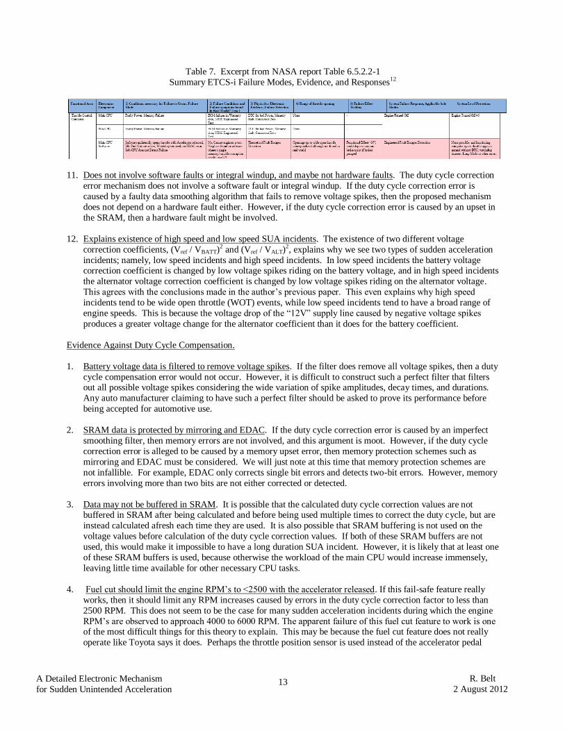
10. Meets NASA criteria for a CPU software error. The NASA report contains a table that summarizes ETCS-i failure modes, evidence, and responses. Table 7 shows an excerpt from NASA’s table (shown in red) which
anticipates that a main CPU software error could occur which unilaterally opens the throttle with the accelerator
released, idle fuel cut not active, watchdog serviced, no EDAC error, and sub-CPU does not detect the failure. It
states that no such error was found but, if it existed then the fault would escape detection, openings of up to wide
open throttle could occur, and no system level protection would be possible because the malfunctioning
computer appears normal without DTC, watchdog timeout, limp home, or other errors. All of these criteria are
met with the proposed duty cycle correction error mechanism discussed in this paper.
Table 6. Fail-safe modes for Toyota vehicles with electronic throttles11
13
A Detailed Electronic Mechanism
for Sudden Unintended Acceleration
R. Belt
2 August 2012
Table 7. Excerpt from NASA report Table 6.5.2.2-1
Summary ETCS-i Failure Modes, Evidence, and Responses12
11. Does not involve software faults or integral windup, and maybe not hardware faults. The duty cycle correction
error mechanism does not involve a software fault or integral windup. If the duty cycle correction error is
caused by a faulty data smoothing algorithm that fails to remove voltage spikes, then the proposed mechanism
does not depend on a hardware fault either. However, if the duty cycle correction error is caused by an upset in
the SRAM, then a hardware fault might be involved.
12. Explains existence of high speed and low speed SUA incidents. The existence of two different voltage
correction coefficients, (Vref / VBATT)2 and (Vref / VALT)2, explains why we see two types of sudden acceleration
incidents; namely, low speed incidents and high speed incidents. In low speed incidents the battery voltage correction coefficient is changed by low voltage spikes riding on the battery voltage, and in high speed incidents
the alternator voltage correction coefficient is changed by low voltage spikes riding on the alternator voltage.
This agrees with the conclusions made in the author’s previous paper. This even explains why high speed
incidents tend to be wide open throttle (WOT) events, while low speed incidents tend to have a broad range of
engine speeds. This is because the voltage drop of the “12V” supply line caused by negative voltage spikes
produces a greater voltage change for the alternator coefficient than it does for the battery coefficient.
Evidence Against Duty Cycle Compensation.
1. Battery voltage data is filtered to remove voltage spikes. If the filter does remove all voltage spikes, then a duty
cycle compensation error would not occur. However, it is difficult to construct such a perfect filter that filters out all possible voltage spikes considering the wide variation of spike amplitudes, decay times, and durations.
Any auto manufacturer claiming to have such a perfect filter should be asked to prove its performance before
being accepted for automotive use.
2. SRAM data is protected by mirroring and EDAC. If the duty cycle correction error is caused by an imperfect
smoothing filter, then memory errors are not involved, and this argument is moot. However, if the duty cycle
correction error is alleged to be caused by a memory upset error, then memory protection schemes such as
mirroring and EDAC must be considered. We will just note at this time that memory protection schemes are
not infallible. For example, EDAC only corrects single bit errors and detects two-bit errors. However, memory
errors involving more than two bits are not either corrected or detected.
3. Data may not be buffered in SRAM. It is possible that the calculated duty cycle correction values are not buffered in SRAM after being calculated and before being used multiple times to correct the duty cycle, but are
instead calculated afresh each time they are used. It is also possible that SRAM buffering is not used on the
voltage values before calculation of the duty cycle correction values. If both of these SRAM buffers are not
used, this would make it impossible to have a long duration SUA incident. However, it is likely that at least one
of these SRAM buffers is used, because otherwise the workload of the main CPU would increase immensely,
leaving little time available for other necessary CPU tasks.
4. Fuel cut should limit the engine RPM’s to <2500 with the accelerator released. If this fail-safe feature really
works, then it should limit any RPM increases caused by errors in the duty cycle correction factor to less than
2500 RPM. This does not seem to be the case for many sudden acceleration incidents during which the engine
RPM’s are observed to approach 4000 to 6000 RPM. The apparent failure of this fuel cut feature to work is one of the most difficult things for this theory to explain. This may be because the fuel cut feature does not really
operate like Toyota says it does. Perhaps the throttle position sensor is used instead of the accelerator pedal
14
A Detailed Electronic Mechanism
for Sudden Unintended Acceleration
R. Belt
2 August 2012
position sensor as the indicator of an idle condition. Toyota should be required to explain how this fuel cut
feature operates, including what signals are involved and how these signals control entry into the fail-safe mode.
IV. Remaining Questions
There are still many questions to be answered regarding Toyota’s electronic throttle design that might throw further light on the duty cycle correction error mechanism discussed in this paper. The following questions are listed so that
answers can be obtained by looking at Toyota’s ETCS-i software or by querying Toyota directly:
1. Is the battery voltage data filtered? Exactly how? Is the filter an analog filter or a digital filter? What is the
algorithm?
2. How often is the battery voltage sampled? By which A/D converter? Is the 10-bit or 12-bit A/D in the sub-
CPU used or the A/D in the main CPU? Which battery voltage signal is sampled? Is it the BM signal?
3. Is a new battery voltage value used for each duty correction to the PID loop?
4. Is the battery voltage data stored temporarily in memory before being used?
a. What memory? Volatile SRAM? Non-volatile SRAM, (i.e., KAM)? Stack?
5. Is the battery voltage data stored temporarily in memory before being used?
a. What memory? Volatile SRAM? Non-volatile SRAM, (i.e., KAM)? Stack?
6. How is the duty correction value obtained? By calculation in the ALU? By look-up table? Where is the look-up table stored?
7. How often is the battery voltage compensation value for the PWM duty changed? Every PID loop time?
8. Is the battery voltage compensation value for the PWM duty re-calculated soon after the engine is started?
When and how often is it calculated thereafter?
9. What are the gain margin and phase margin for the PID loop?
10. What is the gain of the throttle motor? How much does this gain vary due to manufacturing tolerances and
aging? How does it vary with voltage? Provide experimental data of motor gain versus voltage.
11. If a negative spike occurs on the battery voltage line, this will lower the gain of the throttle motor and
increase the gain of the PID controller. Provide an analysis of delays in the CPU and the throttle motor to
show that these two changes in gain coincide in time and cancel each other in magnitude.
12. If the CPU is reset during the PID/PMW calculation, by how much is the phase changed? What is the phase margin with this reset delay added?
13. How does the intermittent fuel cut fail-safe mode operate? What signals control entry into this mode?
Describe how theses control signals control entry into the fail-safe mode.
14. What signals are digitized by the A/D converter in the main CPU? Are these signals used only for
diagnostic purposes, or is one used to modify the PID gain?
15. Are there two duty cycle compensation coefficients for the throttle motor, one for the battery voltage and
one for the alternator voltage? Under what conditions and how often are each one measured?
V. Mitigation Techniques for Duty Cycle Correction Errors
Techniques for mitigating errors in the duty cycle correction value involve removing all negative voltage spikes
from either the sensed battery voltage or from the battery supply line itself. Voltage spikes on the sensed battery voltage can be reduced by developing a more perfect smoothing filter to eliminate the negative spikes. Voltage
spikes on the battery supply line can be reduced by connecting the engine ECM (i.e., PCM) power and ground
inputs directly to the battery terminals instead of to the alternator and the engine block, respectively. This will
eliminate all voltage drops across resistances in battery cables and connectors that are shared by other high-current
loads, leaving only the voltage drop across the battery internal resistance. Shielded wires should be used to avoid
EMI and large enough diameter wire should be used to keep the wire resistance small.
If the duty cycle correction errors are caused by SRAM upsets, then consideration should be given to using a true
non-volatile SRAM, such as ferroelectric RAM (FRAM or FERAM), instead of battery-backed SRAM in the CPUs.
VI. Testing Guidelines for Detecting Duty Cycle Correction Errors
This detailed mechanism for sudden acceleration explains why sudden acceleration has not been observed while
injecting negative voltage spikes on the battery supply line during transient testing. The reason is that the spikes on
the supply line must coincide with the A/D converter sampling time for the battery voltage acquired by the sub-

15
A Detailed Electronic Mechanism
for Sudden Unintended Acceleration
R. Belt
2 August 2012
CPU. If the sub-CPU does not sample the voltage spike, then the voltage spike does not exist as far as the proposed
error mechanism is concerned. Unfortunately, the sampling time for the battery voltage in the sub-CPU is not
known at this time. However, it could be determined by querying the auto manufacturer. Then one would need to
synchronize the injected voltage spike with the sampling time of the sub-CPU. Also, the duration of the voltage
spike may be critical, because the A/D converter may take several samples in quick succession to define a better
baseline for spike determination.
If the sampling time is not disclosed by the auto manufacturer, then one needs to do a lot of experimentation to find
the sampling time before a meaningful test can be done. This can be done by switching the A/D input from a high
voltage (e.g., 14.4V) to a low voltage (e.g., 9V) and using a scan tool to check when the battery voltage in the ECM
changes from 14.4V to 9V. By repeating this at shorter and shorter time intervals, one can try to narrow down the
A/D sampling time. It is difficult and time consuming, however, to determine the A/D sampling time with sufficient
accuracy using this method to do a test with a normal voltage spike having a short duration (10 to 500 msec).
A better way to do this test is to apply a DC voltage of around 8 to 9 volts to the battery voltage input (BM input on
a Toyota) of the ECM (i.e., the same voltage as a voltage spike that is slightly above the voltage level able to cause a
CPU reset). One can then confirm when the applied voltage has been sampled by the CPU by using a scan tool to
read the battery voltage and seeing if it corresponds to the voltage that is being applied (a data stream of 10 samples/sec can be read by some scan tools)
13. When the voltage sampling has been confirmed, one merely needs to
raise the applied BM voltage suddenly to 12.6V or 14.4V, which will cause the motor control loop to assume a
condition exactly like the one produced by a voltage correction coefficient resulting from a negative voltage spike.
This test should be done with the engine running and the transmission in DRIVE, and not in PARK.
VII. Conclusion
A detailed electronic mechanism for sudden unintended acceleration has been proposed. The mechanism involves
an error in the duty cycle correction factor that corrects for a low battery voltage on the throttle motor power supply.
The low battery voltage causes the throttle motor to have less torque, which changes the accelerator response and
limits the engine RPM’s. The duty cycle correction value compensates for this effect by increasing the gain of the PID controller to produce a higher duty cycle current to the throttle motor. This design works well for DC voltages.
However, if a voltage spike on the battery supply line causes a temporary increase in the duty cycle correction factor
that is not coincident with a decrease in the throttle motor current, then there will be a net increase in the PID loop
gain causing an increase in the throttle position. This increase can amount to a factor of three or more for voltage
spikes as low as 8V, which causes the throttle to increase suddenly from an idle position to a wide open throttle
position without the driver’s input. This causes the engine RPM’s to increase suddenly from 800 RPM to 4000 to
6000 RPM, as observed in many sudden acceleration incidents. Medium size voltage spikes between 12.6V and 8V
will cause a smaller throttle increase with smaller RPM values on the order of 2000 to 3000 RPM, as observed in
many other sudden acceleration incidents. Smaller voltage spikes can cause engine surges or lurches. The duration
of these sudden acceleration incidents is explained by the data flow within the main CPU of the ECM. Mitigation
techniques are discussed, and questions are provided to obtain a deeper understanding of some remaining details
from the auto manufacturer.
VIII. References
1 The author’s previous paper is available at http://www.antony-anderson.com/Cruise/belt-hypo/sum.html. 2 This method of reading redacted portions only works for text and some tables. It does not work for figures or for
tables embedded into a document as objects. 3 NASA NESC Technical Assessment Report, “NHTSA Toyota Unintended Acceleration Investigation – Appendix
A. Software”, January 18, 2011, (revised April 15, 2011), p. 71 of 134. 4 NASA NESC Technical Assessment Report, “NHTSA Toyota Unintended Acceleration Investigation – Appendix
A. Software”, January 18, 2011, (revised April 15, 2011), p. 93 of 134. 5 There is a subtle difference between Fig 6 and the real world. Fig 6 implies that sampling is done on the difference between the negative spike and its delayed value. In the real world, sampling is done on the negative spike prior to
its delay and the difference being taken. The author believes that these two sequences of operations yield the same
result, and that the mathematical operations involved can be shown to be equivalent using operator theory, which
shows that the delay and sampling operators are commutative.
16
A Detailed Electronic Mechanism
for Sudden Unintended Acceleration
R. Belt
2 August 2012
6 Cobb Tuning Inc, “A Brief Study Analyzing the Effects that Throttle Mapping have on Engine Output on the MS3”,
http://www.accessecu.com/accessport/Technical%20Documents/A%20Brief%20Study%20Analyzing%20the%20Ef
fects%20of%20Throttle%20Mapping%20and%20Engine%20Output%20on%20the%20MS3%20v1.01.pdf 7 There is also an A/D converter on the main CPU chip that could be used for digitizing the battery voltage, in which
case the digitized voltage could be placed in the SRAM of the main CPU in the same manner as described for the sub-CPU. However, this would require that the subsequent digital filtering operations be performed in the main
CPU, which would increase the work load of the main CPU, leaving less time for other engine functions. 8 The following patents discuss digital filters for removing spikes from a data stream:
a. T. Honda, U. S. Patent 6933867, “A/D Conversion Processing Apparatus providing Improved
Elimination of Effects of Noise Through Digital Processing, Method of Utilizing the A/D Apparatus, and
Electronic Control Apparatus incorporating the A/D Conversion Processing Apparatus”, August 23,
2005, assigned to Denso.
b. A. Kunihiro, U. S. Patent 5025259, “Analog-to-Digital Conversion System for Electronic Control
System of a Motor Vehicle”, June 18, 1991, assigned to Toyota.
c. D. J. Trapasso, U. S. Patent 7010414, “Method for Reducing Computational Time for Calculating a
Noise-Filtered Average Approximation of Throttle Position”, March 7, 2006, assigned to Delphi
Technologies. d. A. J. Kotwicki, et. al, U. S. Patent 6112724, “Throttle Position Filtering Method”, September 5, 2000,
assigned to Ford Global Technologies. 9 Y. Takeuchi, U. S. Patent 8131455, “Engine Control Apparatus Including Computing Section and A/D Converting
Section ”, March 6, 2012, assigned to Denso. 10 U. Jung, J. Radeczky, and M. Wirkowski, U.S. Patent 8108124B2, “Method for Determining An Uncontrolled
Acceleration of an Internal Combustion Engine”, Jan 31, 2012, assigned to Continental Automotive Gmbh. 11 NASA NESC Technical Assessment Report, “NHTSA Toyota Unintended Acceleration Investigation – UA
Report”, January 18, 2011, (revised April 15, 2011), p. 79 of 177. 12 NASA NESC Technical Assessment Report, “NHTSA Toyota Unintended Acceleration Investigation – UA
Report”, January 18, 2011, (revised April 15, 2011), p. 78 of 177. 13 The battery voltage is not an OBDII specified parameter, so it may not be readable by all OBDII scan tools.
However, some scan tools can still read the battery voltage.
17
A Detailed Electronic Mechanism
for Sudden Unintended Acceleration
R. Belt
2 August 2012
Appendix I. NASA Tests of the Throttle Control Loop
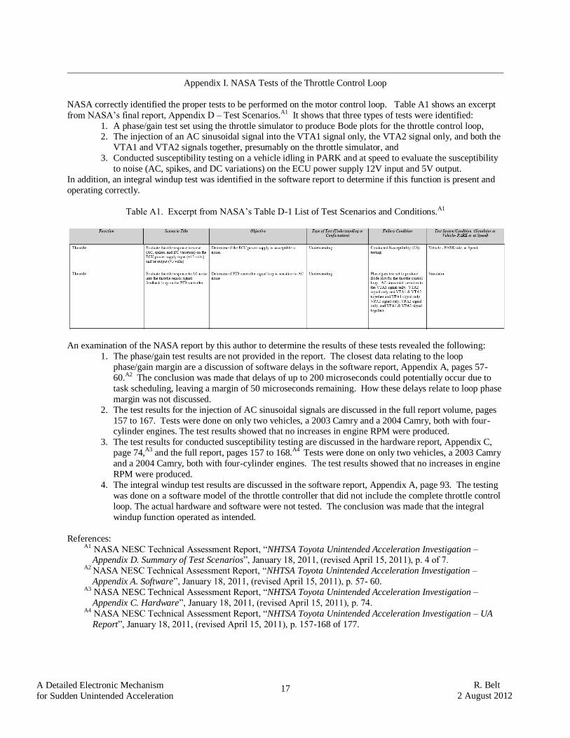
NASA correctly identified the proper tests to be performed on the motor control loop. Table A1 shows an excerpt
from NASA’s final report, Appendix D – Test Scenarios.A1 It shows that three types of tests were identified:
1. A phase/gain test set using the throttle simulator to produce Bode plots for the throttle control loop, 2. The injection of an AC sinusoidal signal into the VTA1 signal only, the VTA2 signal only, and both the
VTA1 and VTA2 signals together, presumably on the throttle simulator, and
3. Conducted susceptibility testing on a vehicle idling in PARK and at speed to evaluate the susceptibility
to noise (AC, spikes, and DC variations) on the ECU power supply 12V input and 5V output.
In addition, an integral windup test was identified in the software report to determine if this function is present and
operating correctly.
Table A1. Excerpt from NASA’s Table D-1 List of Test Scenarios and Conditions.A1
An examination of the NASA report by this author to determine the results of these tests revealed the following:
1. The phase/gain test results are not provided in the report. The closest data relating to the loop
phase/gain margin are a discussion of software delays in the software report, Appendix A, pages 57-
60.A2 The conclusion was made that delays of up to 200 microseconds could potentially occur due to
task scheduling, leaving a margin of 50 microseconds remaining. How these delays relate to loop phase
margin was not discussed.
2. The test results for the injection of AC sinusoidal signals are discussed in the full report volume, pages
157 to 167. Tests were done on only two vehicles, a 2003 Camry and a 2004 Camry, both with four-cylinder engines. The test results showed that no increases in engine RPM were produced.
3. The test results for conducted susceptibility testing are discussed in the hardware report, Appendix C,
page 74,A3 and the full report, pages 157 to 168.A4 Tests were done on only two vehicles, a 2003 Camry
and a 2004 Camry, both with four-cylinder engines. The test results showed that no increases in engine
RPM were produced.
4. The integral windup test results are discussed in the software report, Appendix A, page 93. The testing
was done on a software model of the throttle controller that did not include the complete throttle control
loop. The actual hardware and software were not tested. The conclusion was made that the integral
windup function operated as intended.
References: A1 NASA NESC Technical Assessment Report, “NHTSA Toyota Unintended Acceleration Investigation –
Appendix D. Summary of Test Scenarios”, January 18, 2011, (revised April 15, 2011), p. 4 of 7. A2 NASA NESC Technical Assessment Report, “NHTSA Toyota Unintended Acceleration Investigation –
Appendix A. Software”, January 18, 2011, (revised April 15, 2011), p. 57- 60. A3 NASA NESC Technical Assessment Report, “NHTSA Toyota Unintended Acceleration Investigation –
Appendix C. Hardware”, January 18, 2011, (revised April 15, 2011), p. 74. A4 NASA NESC Technical Assessment Report, “NHTSA Toyota Unintended Acceleration Investigation – UA
Report”, January 18, 2011, (revised April 15, 2011), p. 157-168 of 177.