Embed Size (px)
Citation preview
A DIELECTRIC METHOD FOR DETERMINING SOIL MOISTURE1
JOEL E. FLETCHER2
ELECTRICAL conductivity methods of deter-mining soil moisture have failed in the South-
west because of the comparatively high concentrationsof soluble salts commonly occurring in the soil. Thetensiometer set-ups have not been very successfulbecause of the dry conditions which prevail part ofthe year. Such dry conditions break the water col-umns, necessitating replacement before further resultscan be obtained. The method of taking samples is tootedious and requires an undue amount of disturbancein the surface of plots or lysimeters.3 To be satis-factory, a method for determining soil moisture mustbe independent to a large degree of the salt contentof the soil. It must be reasonably accurate over thecomplete range of moisture contents commonly en-countered in a given area. It must be rapid and simpleto operate. It must be applicable to soils in situ. Itshould be affected only slightly by changes in tem-perature, and it is desirable that the apparatus usedbe easily portable.
A consideration of soil properties which lend them-selves to rapid methods of moisture determinationshow the electrical properties, the dielectric constantand conductivity, to be among the foremost. The highdielectric constant for water and the low constant forsoil are well known from reports in the literature(i, 2, 5, 7, 9, n, i5).4
The majority of these investigators were interestedprimarily in radio broadcasting and two of the soilproperties which have been found to influence broad-casting are conductivity and dielectric constant. Theinvestigators have also shown the effect of soil mois-ture, frequency, temperature and salt content on theseproperties. Nearly all of them noted that the relationbetween the dielectric constant and the moisture con-tent tended to be linear in the lower ranges of mois-ture content.
Edlefsen (9, 10) made a brief review of dielectricmethods of determining moisture in various sub-stances and even suggested its use for soils but theinvestigation has not been completed.
DESCRIPTION OF APPARATUSFrom a survey of the literature already mentioned and
others (3, 4, 6, 8, 12, 13, 14, 18) it was decided that aresonance method of determining the dielectric constant wouldbe best adapted to portable work where leaky condenserswere to be encountered. A number of hook-ups have beentried, but the one with which these results were obtained isshown schematically in Fig. i and the apparatus in Fig. 2.Several improvements are contemplated for the future butthey are not of major character.
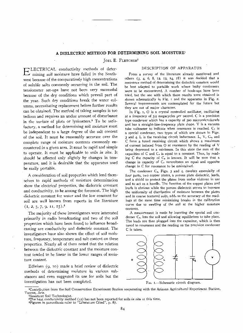
In Fig. i, O is a crystal controlled oscillator, oscillatingat a frequency of 3.9 megacycles per second. C is a precisiontype condenser which has a capacity of 500 micromicrofaradsand has a straight-line-frequency plate shape. V is a vacuumtube voltmeter to indicate when resonance is reached. Cs isa special condenser, two types of which are shown in Figs.3 and 4. L is the receiving circuit inductance. L, V, C», andC form a tuned receiving circuit which shows a maximumof current induced from O at resonance by the reading of Vbeing depressed to a minimum. In this state the sum of thecapacities of C and C, is equal to a constant. Thus, by read-ing C the capacity of C, is known. It will be seen that achange in capacity of C, necessitates an equal and oppositechange in C for resonance to be maintained.
The condenser CB, Figs. 3 and 4, consists essentially offour parts, two copper plates, a porous plate dielectric, leads,and a shield to protect the plates from undue violence in useand to act as a handle. The function of the copper plates andleads is obvious while the porous dielectric serves to increasethe uniformity of distribution of moisture between the platesand in coarse textured soils, adds to the accuracy of the read-ings at the same time minimizing breaks in the calibrationcurve due to swelling of the soil at the higher moisturecontents.
A measurement is made by inserting the special soil con-denser Cs, into the soil and allowing equilibrium to take place.The leads are then plugged into the capacitor, which is thentuned to resonance and the reading on the precision condenserC is taken.
FIG. i.—Schematic circuit diagram.
'Contribution from the Soil Conservation Experiment Station cooperating with the Arizona Agricultural Experiment Station,Tuscon, Ariz.
2Assistant Soil Technologist.3The heat conductivity method (12) has not been reported for soils in situ at this time.4Figures in parenthesis refer to "Literature Cited", p. 87.
84
FLETCHER: DIELECTRIC METHOD FOR DETERMINING SOIL MOISTURE
condenser the curve has a flatter slope and the pointsshow a greater variability than in the case of the othercondenser. The points on these curves were foundby burying a condenser in the soil in a large porousearthen pot, wetting the soil and taking capacityreadings and moisture samples as the soil dried. Themoisture content shown is the mean of three samplestaken near the condenser and dried at 105 degrees C.All of the soils were wet so an excess of water waspresent at the beginning of the run.
The curves in Fig. 6 are of two general types, thosemade by adding a measured volume of water to aweighed soil sample, which is then mixed and tested(dashed lines) and those made by drying a wet sam-ple, recording the weight and readings on the wholesample as it drys. The water is recorded as cc ofwater per 100 grams of soil above the content at thedriest point in the experiment which was alwayseither air dry or wetter. The several condensers usedto obtain these curves were all plate type with soilpacked between the plates for the dielectric ratherthan a porous plate. The first bend in these curves is
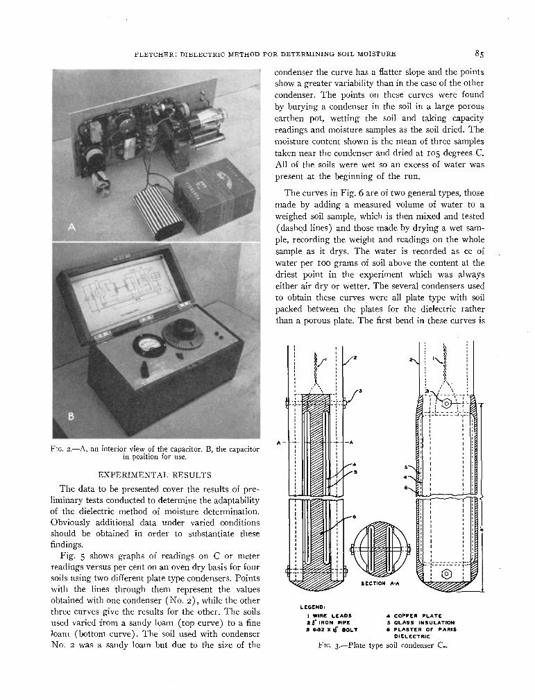
FIG. 2.—A, an interior view of the capacitor. B, the capacitorin position for use.
EXPERIMENTAL RESULTSThe data to be presented cover the results of pre-
liminary tests conducted to determine the adaptabilityof the dielectric method of moisture determination.Obviously additional data under varied conditionsshould be obtained in order to substantiate thesefindings.
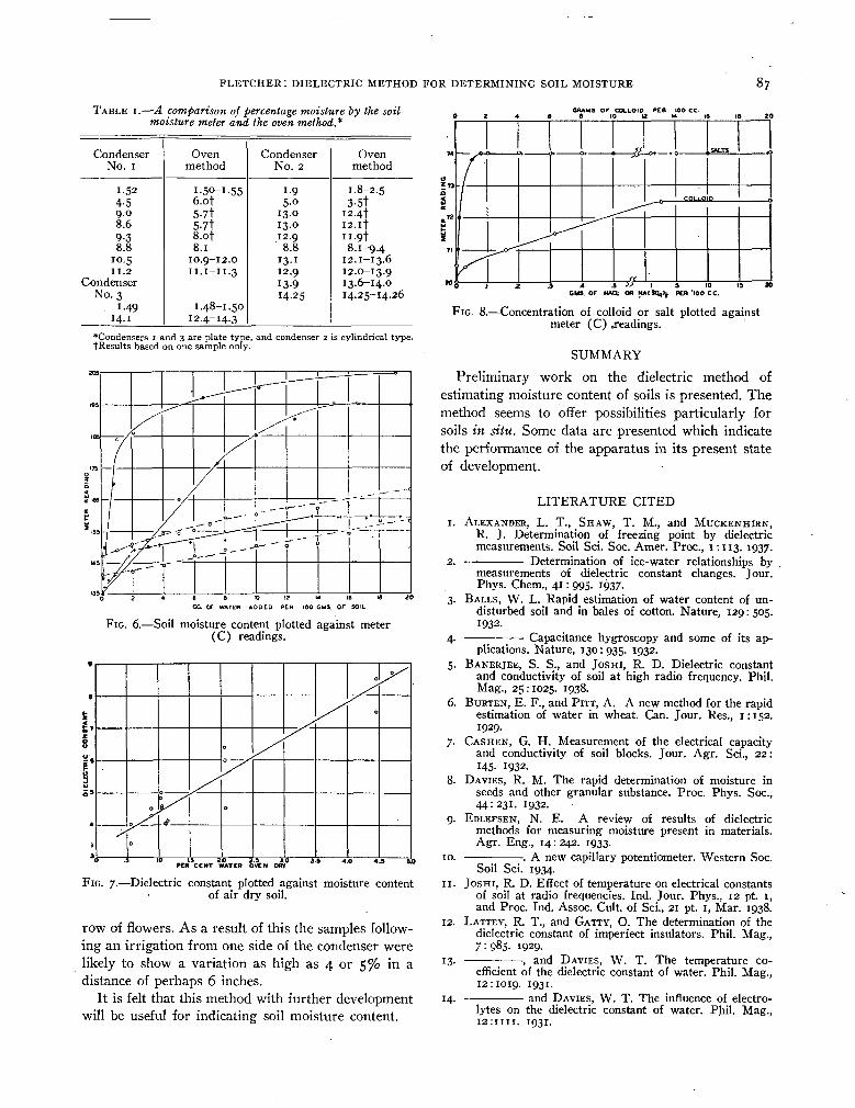
Fig. 5 shows graphs of readings on C or meterreadings versus per cent on an oven dry basis for foursoils using two different plate type condensers. Pointswith the lines through them represent the valuesobtained with one condenser (No. 2), while the otherthree curves give the results for the other. The soilsused varied from a sandy loam (top curve) to a fineloam (bottom curve). The soil used with condenserNo. 2 was a sandy loam but due to the size of the
LEGEND:
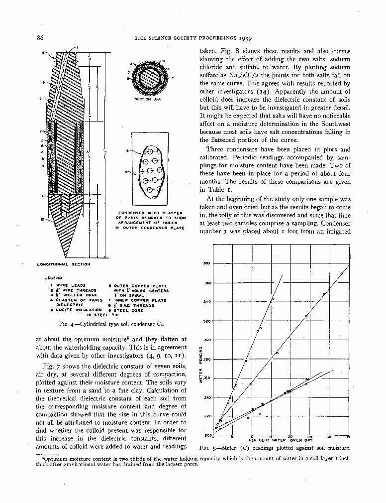
1 WIRE LEADS2 |* IRON PIPE3 6-32 X tf BOLT
4 COPPER PLATE5 GLASS INSULATION6 PLASTER OF PARIS
DIELECTRIC
FIG. 3.—Plate type soil condenser Ca.
86 SOIL SCIENCE SOCIETY PROCEEDINGS IQ39
SECTION A-A
CONDENSER WITH PLASTEROF PARIS REMOVED TO SHOW
ARRANGEMENT OF HOLESIN OUTER CONDENSER PLATE
LONGITUDINAL SECTION
LEGEND'
1 WIRE LEADS2 J" PIPE THREADS3 $" DRILLED HOLE4 PLASTER Or PARIS
DIELECTRIC5 LUCITE INSULATION
6 OUTER COPPER PLATEWITH i' HOLES. CENTERS4 ON SPIRAL
7 INNER COPPER PLATE8 {' S.A£. THREADS» STEEL CORE
10 STEEL TIP
FIG. 4.—Cylindrical type soil condenser C».
at about the optimum moisture5 and they flatten atabout the waterholding capacity. This is in agreementwith data given by other investigators (4, 9, 10, n).
Fig. 7 shows the dielectric constant of seven soils,air dry, at several different degrees of compaction,plotted against their moisture content. The soils varyin texture from a sand to a fine clay. Calculation ofthe theoretical dielectric constant of each soil fromthe corresponding moisture content and degree ofcompaction showed that the rise in this curve couldnot all be attributed to moisture content. In order tofind whether the colloid present was responsible forthis increase in the dielectric constants, differentamounts of colloid were added to water and readings
taken. Fig. 8 shows these results and also curvesshowing the effect of adding the two salts, sodiumchloride and sulfate, to water. By plotting sodiumsulfate as Na2SC>4/2 the points for both salts fall onthe same curve. This agrees with results reported byother investigators (14). Apparently the amount ofcolloid does increase the dielectric constant of soilsbut this will have to be investigated in greater detail.It might be expected that salts will have no noticeableaffect on a moisture determination in the Southwestbecause most soils have salt concentrations falling inthe flattened portion of the curve.
Three condensers have been placed in plots andcalibrated. Periodic readings accompanied by sam-plings for moisture content have been made. Two ofthese have been in place for a period of about fourmonths. The results of these comparisons are givenin Table i.
At the beginning of the study only one sample wastaken and oven dried but as the results began to comein, the folly of this was discovered and since that timeat least two samples comprise a sampling. Condensernumber i was placed about i foot from an irrigated
PER CENT WVTER OVEN DRY
FIG. 5.—Meter (C) readings plotted against soil moisture.
'Optimum moisture content is two thirds of the water holding capacity which is the amount of water in a soil layer I inchthick after gravitational water has drained from the largest pores.
FLETCHER: DIELECTRIC METHOD FOR DETERMINING SOIL MOISTURE 87TABLE I.—A comparison of percentage moisture by the soil
moisture meter and the oven method*CRAMS OF COLLOID PER IOO CC.
CondenserNo. i
i-524-59.08.69-38.8
10.5II. 2
CondenserNo. 3
1-4914-1
Ovenmethod
I-50-I.556.o|5-7t5-7t8.of8.1
10.9-12.011. 1-11.3
1.48-1.5012.4-14.3
CondenserNo. 2
1-95-0
13-013.012.98.8
13-112.913-914-25
Ovenmethod
1.8-2.53-5t
I2-4t12. ifu-9t8.1-9.4
12.1-13.612.0-13.913.6-14.014.25-14.26
*Condensers i and 3 are plate type, and condenser 2 is cylindrical type.tResults based on one sample only.
FIG. 6.—Soil moisture content plotted against meter(C) readings.
LS 2jO 2.5 3.0PER CENT WATER OVEN DRY
FIG. 7.—Dielectric constant plotted against moisture contentof air dry soil.
row of flowers. As a result of this the samples follow-ing an irrigation from one side of the condenser werelikely to show a variation as high as 4 or 5% in adistance of perhaps 6 inches.
It is felt that this method with further developmentwill be useful for indicating soil moisture content.
CMS. OF NAO. OR NAlSO^t PER •iDO CC.
FIG. 8.—Concentration of colloid or salt plotted againstmeter (C) .readings.
SUMMARYPreliminary work on the dielectric method of
estimating moisture content of soils is presented. Themethod seems to offer possibilities particularly forsoils in situ. Some data are presented which indicatethe performance of the apparatus in its present stateof development.
88 SOIL SCIENCE SOCIETY PROCEEDINGS 1939