Embed Size (px)
Citation preview
٢٣
(a) diffusion pump: 1.High vacuum; 2.Water cooling; 3.First stage; 4.Second stage; 5.Pump oil; 6.Heater; 7.Fore-vacuum; (b) vapour pump; 1.Intake port;
2.Fore-vacuum; 3.Oil; 4.Heater. Vapour Ejector pumps:
Ejector pump work with oil or steam. The pump fluid is contained in the boiler
(10) and the vapour flows through the jet chimneys (8,9) into the nozzle (2,4).
Due to their special shape each of these nozzles produces a supersonic jet, which
enters the nozzles (diffusers 3,5) and condenses on their cooled walls. The air to
be pumped enters the pump through the high vacuum connection (1), and is
carried with the jet and compressed. The process is repeated in the second stage.
The air compressed to a pressure equivalent to that of the fore-vacuum line (6) is
removed by the backing pump. The condensed fluid flows back through the
return pipe (7).
Double-stage oil-vapour ejector pum
٢٤
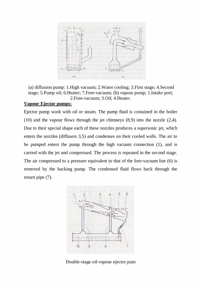
Diffusion pumps:
Oil diffusion pump; 1.Pump inlet, high vacuum; 2.First stage; 3.Second stage; 4.Third stage; 5. Ejector; 6.Pump fluid; 7.Fractionating boiler; 8.Heater; 9.Water
cooling coil; 10.Forline baffle; 11.Backing line, fore-vacuum.
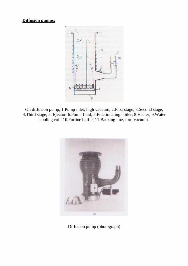
Diffusion pump (photograph)
٢٥
pumps:-ion-Sputter
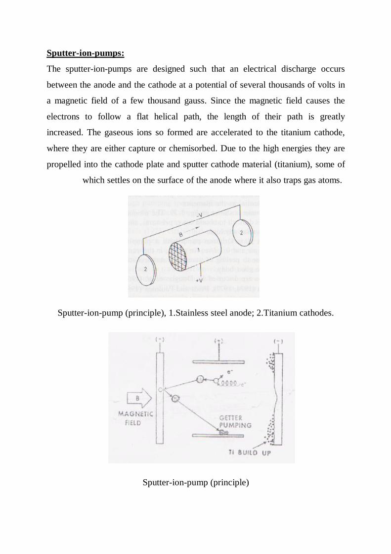
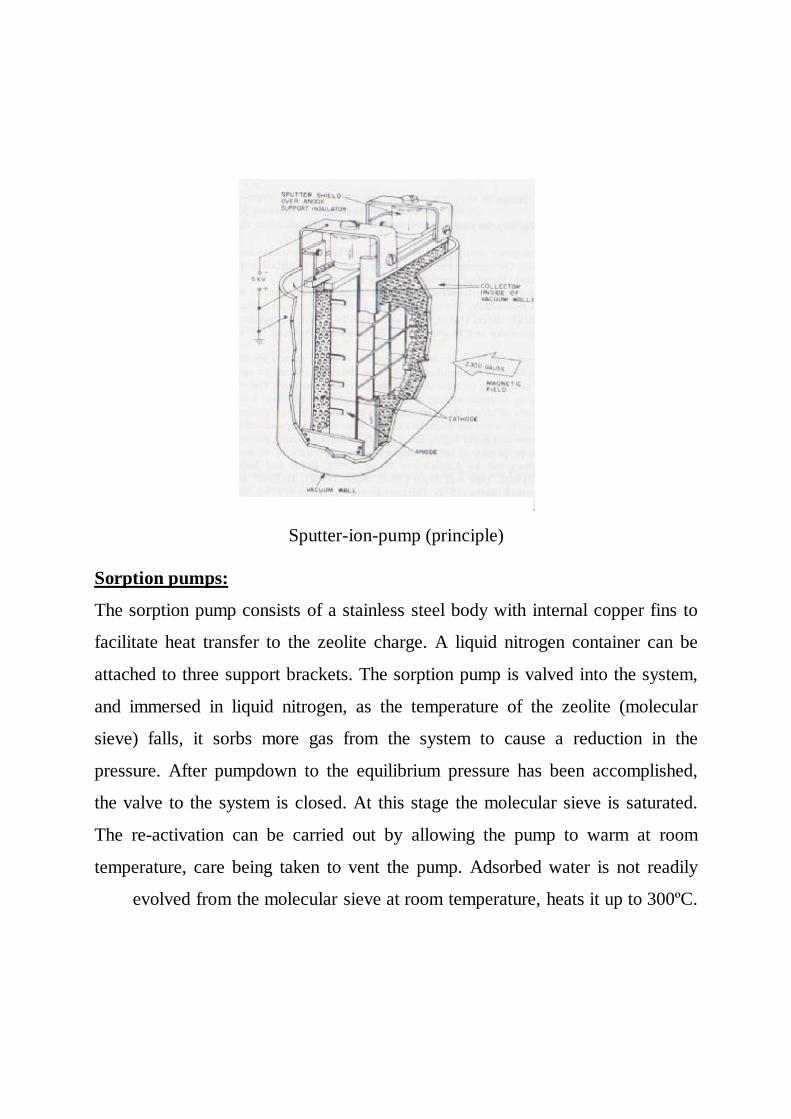
The sputter-ion-pumps are designed such that an electrical discharge occurs
between the anode and the cathode at a potential of several thousands of volts in
a magnetic field of a few thousand gauss. Since the magnetic field causes the
electrons to follow a flat helical path, the length of their path is greatly
increased. The gaseous ions so formed are accelerated to the titanium cathode,
where they are either capture or chemisorbed. Due to the high energies they are
propelled into the cathode plate and sputter cathode material (titanium), some of
which settles on the surface of the anode where it also traps gas atoms.
Sputter-ion-pump (principle), 1.Stainless steel anode; 2.Titanium cathodes.
Sputter-ion-pump (principle)
٢٦
Sputter-ion-pump (principle)
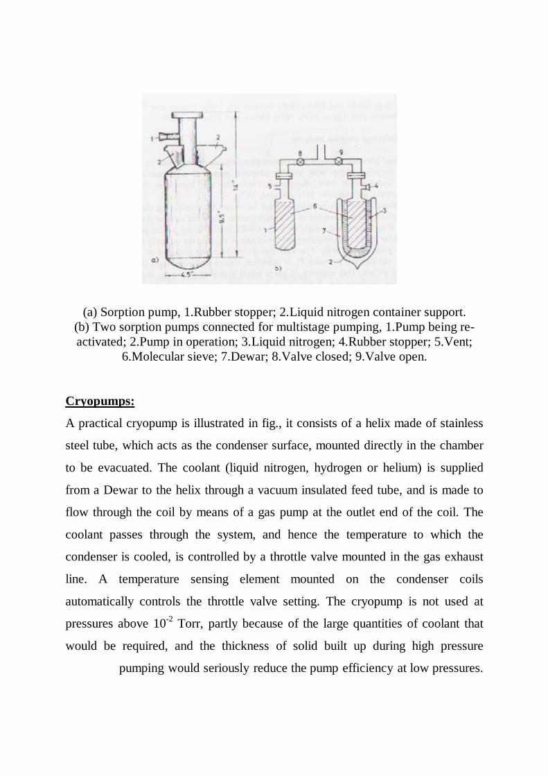
Sorption pumps:
The sorption pump consists of a stainless steel body with internal copper fins to
facilitate heat transfer to the zeolite charge. A liquid nitrogen container can be
attached to three support brackets. The sorption pump is valved into the system,
and immersed in liquid nitrogen, as the temperature of the zeolite (molecular
sieve) falls, it sorbs more gas from the system to cause a reduction in the
pressure. After pumpdown to the equilibrium pressure has been accomplished,
the valve to the system is closed. At this stage the molecular sieve is saturated.
The re-activation can be carried out by allowing the pump to warm at room
temperature, care being taken to vent the pump. Adsorbed water is not readily
evolved from the molecular sieve at room temperature, heats it up to 300ºC.
٢٧
(a) Sorption pump, 1.Rubber stopper; 2.Liquid nitrogen container support. (b) Two sorption pumps connected for multistage pumping, 1.Pump being re-activated; 2.Pump in operation; 3.Liquid nitrogen; 4.Rubber stopper; 5.Vent;
6.Molecular sieve; 7.Dewar; 8.Valve closed; 9.Valve open.
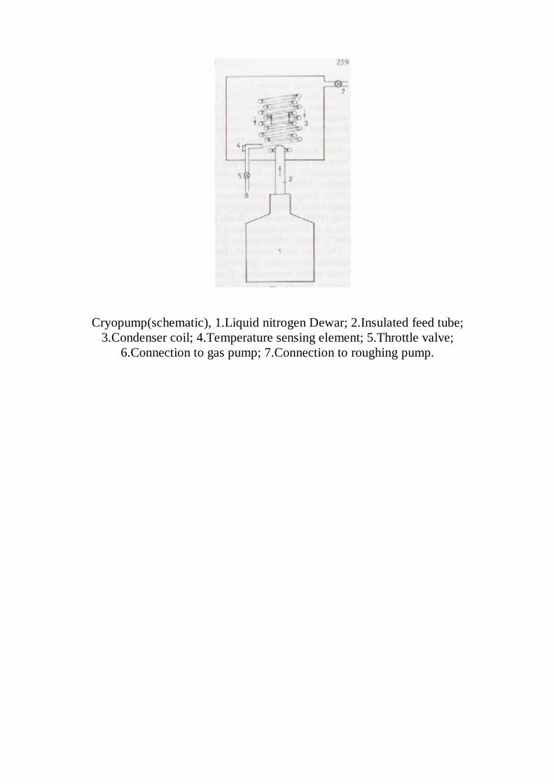
Cryopumps:
A practical cryopump is illustrated in fig., it consists of a helix made of stainless
steel tube, which acts as the condenser surface, mounted directly in the chamber
to be evacuated. The coolant (liquid nitrogen, hydrogen or helium) is supplied
from a Dewar to the helix through a vacuum insulated feed tube, and is made to
flow through the coil by means of a gas pump at the outlet end of the coil. The
coolant passes through the system, and hence the temperature to which the
condenser is cooled, is controlled by a throttle valve mounted in the gas exhaust
line. A temperature sensing element mounted on the condenser coils
automatically controls the throttle valve setting. The cryopump is not used at
pressures above 10-2 Torr, partly because of the large quantities of coolant that
would be required, and the thickness of solid built up during high pressure
pumping would seriously reduce the pump efficiency at low pressures.
٢٨
Cryopump(schematic), 1.Liquid nitrogen Dewar; 2.Insulated feed tube; 3.Condenser coil; 4.Temperature sensing element; 5.Throttle valve;
6.Connection to gas pump; 7.Connection to roughing pump.
٢٩
Measurement of low pressures
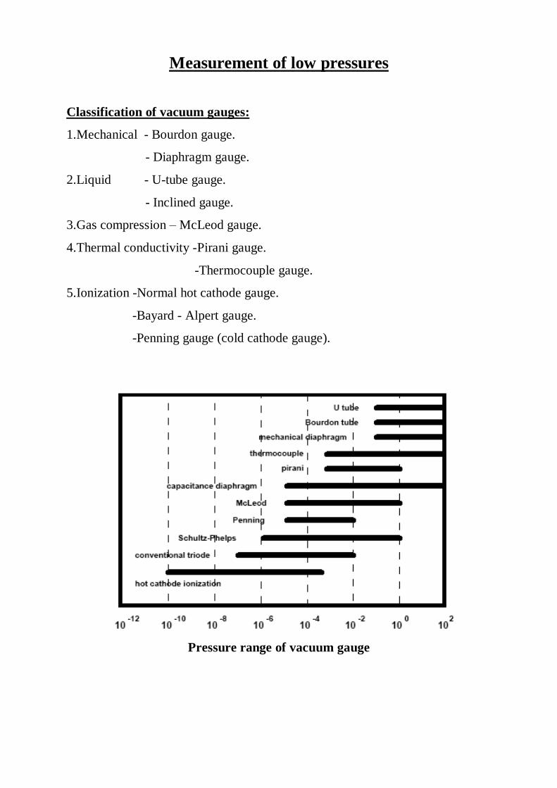
Classification of vacuum gauges:
1.Mechanical - Bourdon gauge.
- Diaphragm gauge.
2.Liquid - U-tube gauge.
- Inclined gauge.
3.Gas compression – McLeod gauge.
4.Thermal conductivity -Pirani gauge.
-Thermocouple gauge.
5.Ionization -Normal hot cathode gauge.
-Bayard - Alpert gauge.
-Penning gauge (cold cathode gauge).
Pressure range of vacuum gauge
٣٠
Mechanical gauge:
gauge: tube 1.Bourdon
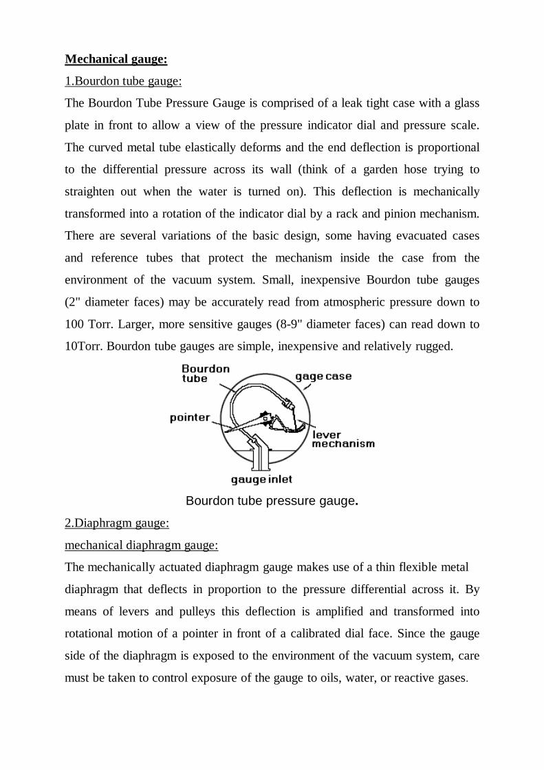
The Bourdon Tube Pressure Gauge is comprised of a leak tight case with a glass
plate in front to allow a view of the pressure indicator dial and pressure scale.
The curved metal tube elastically deforms and the end deflection is proportional
to the differential pressure across its wall (think of a garden hose trying to
straighten out when the water is turned on). This deflection is mechanically
transformed into a rotation of the indicator dial by a rack and pinion mechanism.
There are several variations of the basic design, some having evacuated cases
and reference tubes that protect the mechanism inside the case from the
environment of the vacuum system. Small, inexpensive Bourdon tube gauges
(2" diameter faces) may be accurately read from atmospheric pressure down to
100 Torr. Larger, more sensitive gauges (8-9" diameter faces) can read down to
10Torr. Bourdon tube gauges are simple, inexpensive and relatively rugged.
Bourdon tube pressure gauge. 2.Diaphragm gauge:
mechanical diaphragm gauge:
The mechanically actuated diaphragm gauge makes use of a thin flexible metal
diaphragm that deflects in proportion to the pressure differential across it. By
means of levers and pulleys this deflection is amplified and transformed into
rotational motion of a pointer in front of a calibrated dial face. Since the gauge
side of the diaphragm is exposed to the environment of the vacuum system, care
must be taken to control exposure of the gauge to oils, water, or reactive gases.
٣١
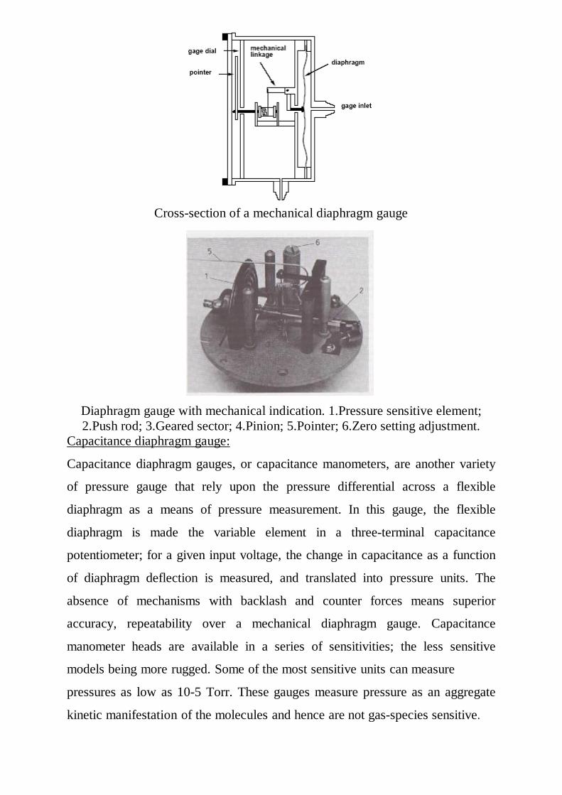
Cross-section of a mechanical diaphragm gauge
Diaphragm gauge with mechanical indication. 1.Pressure sensitive element; 2.Push rod; 3.Geared sector; 4.Pinion; 5.Pointer; 6.Zero setting adjustment.
Capacitance diaphragm gauge:
Capacitance diaphragm gauges, or capacitance manometers, are another variety
of pressure gauge that rely upon the pressure differential across a flexible
diaphragm as a means of pressure measurement. In this gauge, the flexible
diaphragm is made the variable element in a three-terminal capacitance
potentiometer; for a given input voltage, the change in capacitance as a function
of diaphragm deflection is measured, and translated into pressure units. The
absence of mechanisms with backlash and counter forces means superior
accuracy, repeatability over a mechanical diaphragm gauge. Capacitance
manometer heads are available in a series of sensitivities; the less sensitive
models being more rugged. Some of the most sensitive units can measure
pressures as low as 10-5 Torr. These gauges measure pressure as an aggregate
kinetic manifestation of the molecules and hence are not gas-species sensitive.
٣٢
Capacitance gauge head in cross-section. Gauge using liquids:
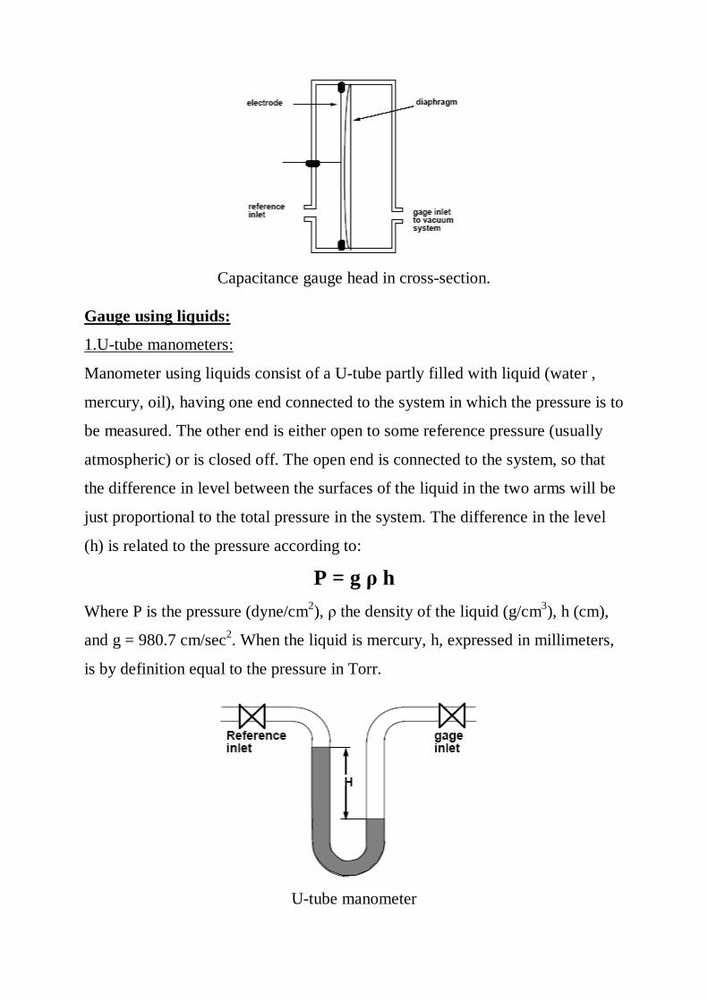
1.U-tube manometers:
Manometer using liquids consist of a U-tube partly filled with liquid (water ,
mercury, oil), having one end connected to the system in which the pressure is to
be measured. The other end is either open to some reference pressure (usually
atmospheric) or is closed off. The open end is connected to the system, so that
the difference in level between the surfaces of the liquid in the two arms will be
just proportional to the total pressure in the system. The difference in the level
(h) is related to the pressure according to:
P = g ρ h Where P is the pressure (dyne/cm2), ρ the density of the liquid (g/cm3), h (cm),
and g = 980.7 cm/sec2. When the liquid is mercury, h, expressed in millimeters,
is by definition equal to the pressure in Torr.
U-tube manometer
٣٣
For lower values of the pressure, various causes produce errors:
1.liquid sticking to glass (variable capillarity).
2.irregular light refraction in the glass.
3.dissolution of gases in the liquid(especially in oil).
4.temperature difference.
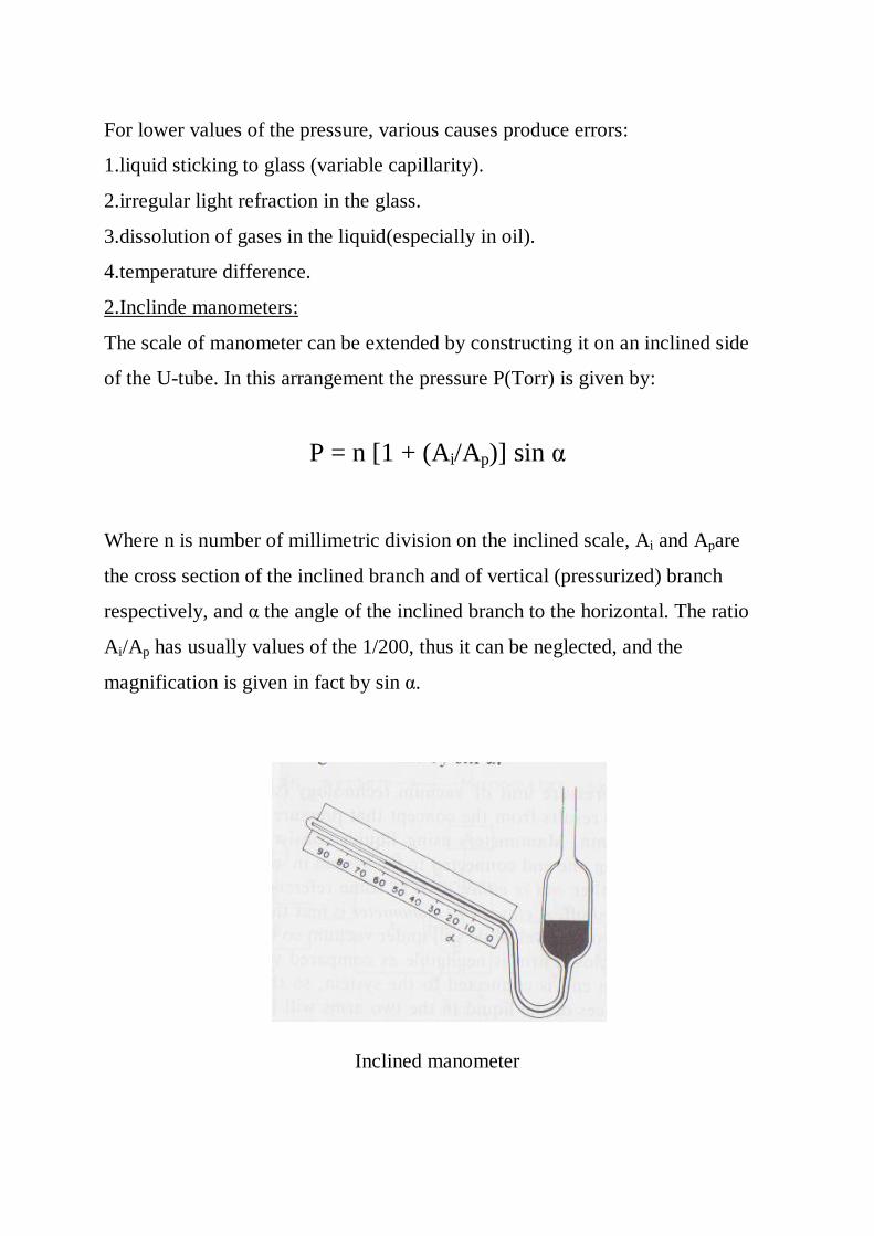
2.Inclinde manometers:
The scale of manometer can be extended by constructing it on an inclined side
of the U-tube. In this arrangement the pressure P(Torr) is given by:
P = n [1 + (Ai/Ap)] sin α
Where n is number of millimetric division on the inclined scale, Ai and Apare
the cross section of the inclined branch and of vertical (pressurized) branch
respectively, and α the angle of the inclined branch to the horizontal. The ratio
Ai/Ap has usually values of the 1/200, thus it can be neglected, and the
magnification is given in fact by sin α.
Inclined manometer
٣٤
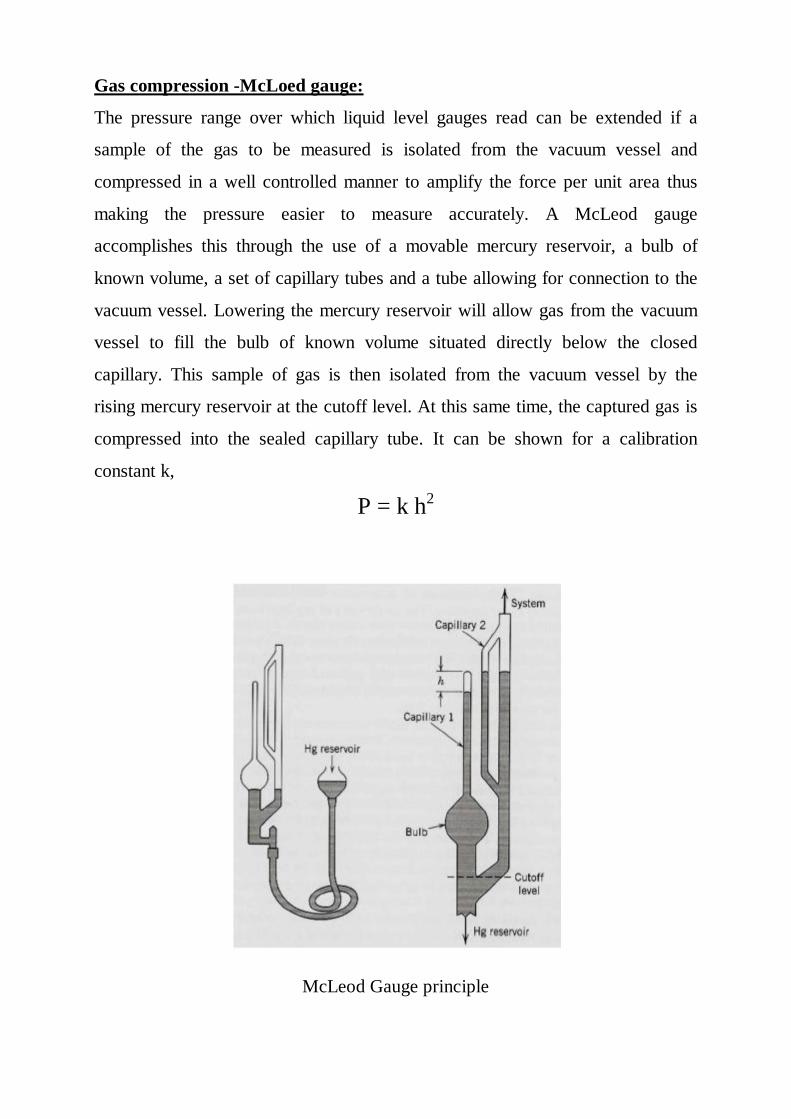
Gas compression -McLoed gauge:
The pressure range over which liquid level gauges read can be extended if a
sample of the gas to be measured is isolated from the vacuum vessel and
compressed in a well controlled manner to amplify the force per unit area thus
making the pressure easier to measure accurately. A McLeod gauge
accomplishes this through the use of a movable mercury reservoir, a bulb of
known volume, a set of capillary tubes and a tube allowing for connection to the
vacuum vessel. Lowering the mercury reservoir will allow gas from the vacuum
vessel to fill the bulb of known volume situated directly below the closed
capillary. This sample of gas is then isolated from the vacuum vessel by the
rising mercury reservoir at the cutoff level. At this same time, the captured gas is
compressed into the sealed capillary tube. It can be shown for a calibration
constant k,
P = k h2
McLeod Gauge principle
٣٥
Thermal Conductivity Gauges:
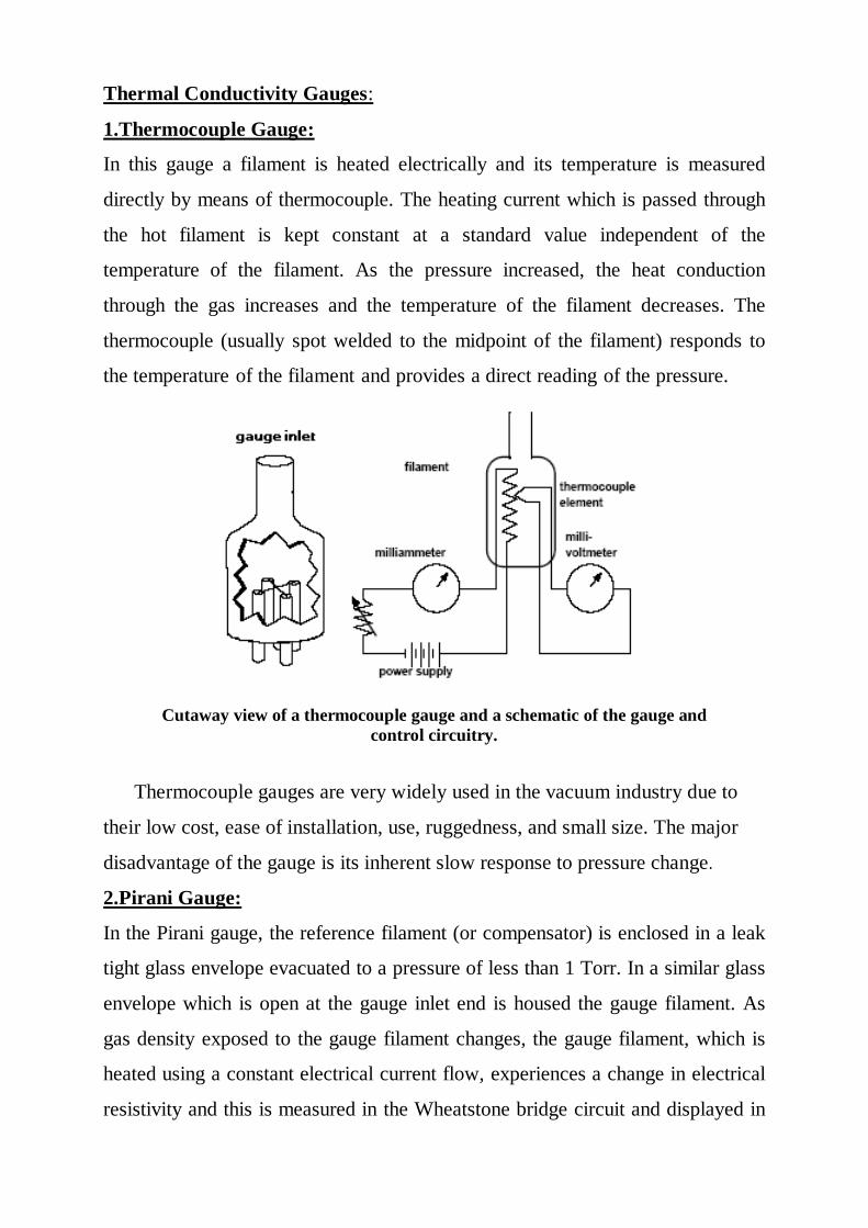
1.Thermocouple Gauge:
In this gauge a filament is heated electrically and its temperature is measured
directly by means of thermocouple. The heating current which is passed through
the hot filament is kept constant at a standard value independent of the
temperature of the filament. As the pressure increased, the heat conduction
through the gas increases and the temperature of the filament decreases. The
thermocouple (usually spot welded to the midpoint of the filament) responds to
the temperature of the filament and provides a direct reading of the pressure.
Cutaway view of a thermocouple gauge and a schematic of the gauge and control circuitry.
Thermocouple gauges are very widely used in the vacuum industry due to
their low cost, ease of installation, use, ruggedness, and small size. The major
disadvantage of the gauge is its inherent slow response to pressure change.
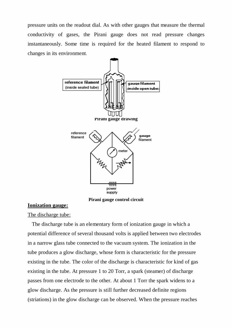
2.Pirani Gauge:
In the Pirani gauge, the reference filament (or compensator) is enclosed in a leak
tight glass envelope evacuated to a pressure of less than 1 Torr. In a similar glass
envelope which is open at the gauge inlet end is housed the gauge filament. As
gas density exposed to the gauge filament changes, the gauge filament, which is
heated using a constant electrical current flow, experiences a change in electrical
resistivity and this is measured in the Wheatstone bridge circuit and displayed in
٣٦
pressure units on the readout dial. As with other gauges that measure the thermal
conductivity of gases, the Pirani gauge does not read pressure changes
instantaneously. Some time is required for the heated filament to respond to
changes in its environment.
Pirani gauge drawing
Pirani gauge control circuit Ionization gauge:
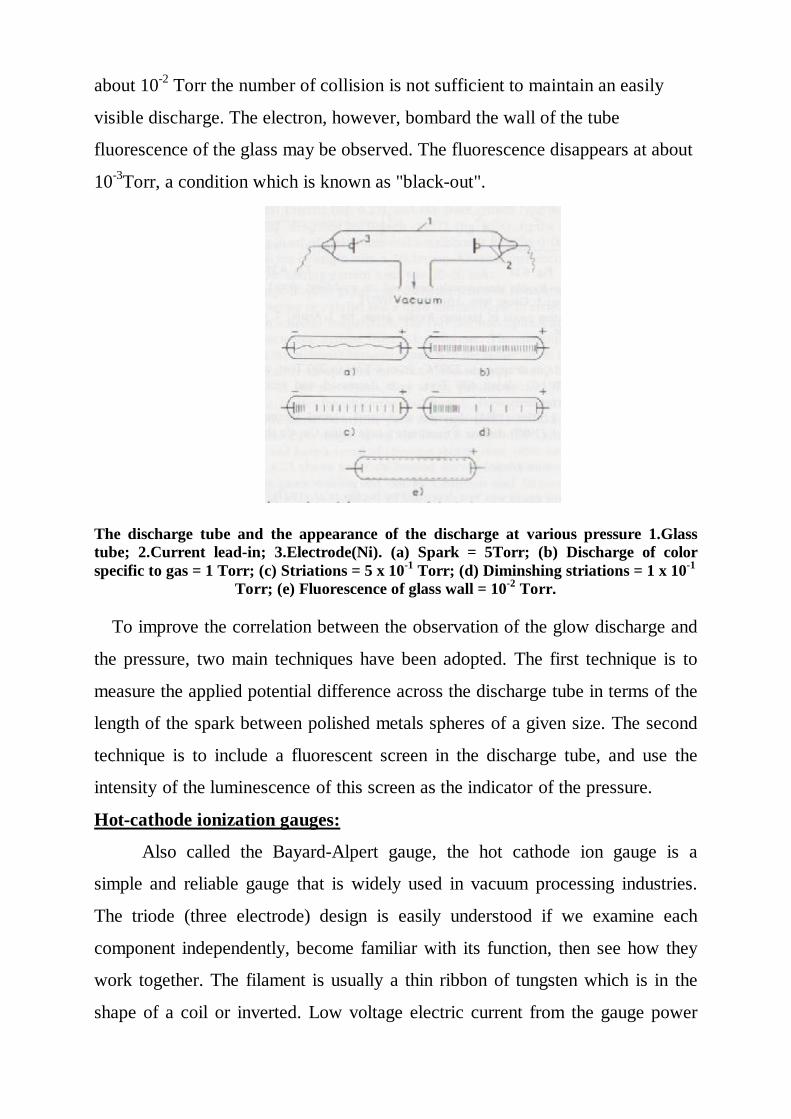
The discharge tube:
The discharge tube is an elementary form of ionization gauge in which a
potential difference of several thousand volts is applied between two electrodes
in a narrow glass tube connected to the vacuum system. The ionization in the
tube produces a glow discharge, whose form is characteristic for the pressure
existing in the tube. The color of the discharge is characteristic for kind of gas
existing in the tube. At pressure 1 to 20 Torr, a spark (steamer) of discharge
passes from one electrode to the other. At about 1 Torr the spark widens to a
glow discharge. As the pressure is still further decreased definite regions
(striations) in the glow discharge can be observed. When the pressure reaches
٣٧
about 10-2 Torr the number of collision is not sufficient to maintain an easily
visible discharge. The electron, however, bombard the wall of the tube
fluorescence of the glass may be observed. The fluorescence disappears at about
10-3Torr, a condition which is known as "black-out".
The discharge tube and the appearance of the discharge at various pressure 1.Glass tube; 2.Current lead-in; 3.Electrode(Ni). (a) Spark = 5Torr; (b) Discharge of color specific to gas = 1 Torr; (c) Striations = 5 x 10⁻¹ Torr; (d) Diminshing striations = 1 x 10⁻¹
Torr; (e) Fluorescence of glass wall = 10-2 Torr.
To improve the correlation between the observation of the glow discharge and
the pressure, two main techniques have been adopted. The first technique is to
measure the applied potential difference across the discharge tube in terms of the
length of the spark between polished metals spheres of a given size. The second
technique is to include a fluorescent screen in the discharge tube, and use the
intensity of the luminescence of this screen as the indicator of the pressure.
Hot-cathode ionization gauges:
Also called the Bayard-Alpert gauge, the hot cathode ion gauge is a
simple and reliable gauge that is widely used in vacuum processing industries.
The triode (three electrode) design is easily understood if we examine each
component independently, become familiar with its function, then see how they
work together. The filament is usually a thin ribbon of tungsten which is in the
shape of a coil or inverted. Low voltage electric current from the gauge power
٣٨
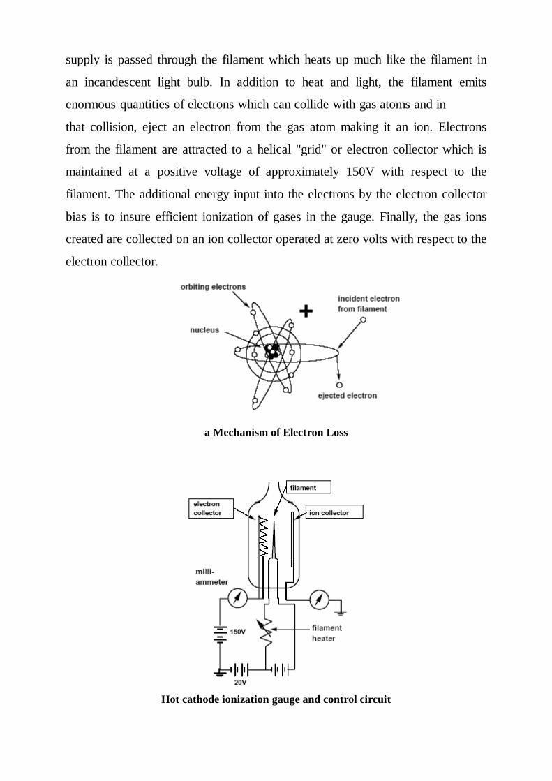
supply is passed through the filament which heats up much like the filament in
an incandescent light bulb. In addition to heat and light, the filament emits
enormous quantities of electrons which can collide with gas atoms and in
that collision, eject an electron from the gas atom making it an ion. Electrons
from the filament are attracted to a helical "grid" or electron collector which is
maintained at a positive voltage of approximately 150V with respect to the
filament. The additional energy input into the electrons by the electron collector
bias is to insure efficient ionization of gases in the gauge. Finally, the gas ions
created are collected on an ion collector operated at zero volts with respect to the
electron collector.
a Mechanism of Electron Loss
Hot cathode ionization gauge and control circuit
٣٩
The operating range of hot cathode ionization gauges is from 10-3 Torr to 10-9
Torr. These gauges are small in size, relatively easy to operate and accurate to
+/- 10% of the reading in the pressure range in which they are designed to
operate.
Cold-cathode ionization gauges: (the penning gauge)
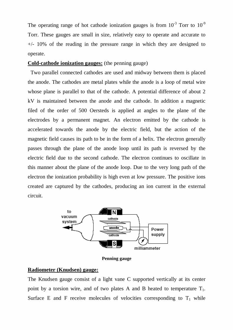
Two parallel connected cathodes are used and midway between them is placed
the anode. The cathodes are metal plates while the anode is a loop of metal wire
whose plane is parallel to that of the cathode. A potential difference of about 2
kV is maintained between the anode and the cathode. In addition a magnetic
filed of the order of 500 Oersteds is applied at angles to the plane of the
electrodes by a permanent magnet. An electron emitted by the cathode is
accelerated towards the anode by the electric field, but the action of the
magnetic field causes its path to be in the form of a helix. The electron generally
passes through the plane of the anode loop until its path is reversed by the
electric field due to the second cathode. The electron continues to oscillate in
this manner about the plane of the anode loop. Due to the very long path of the
electron the ionization probability is high even at low pressure. The positive ions
created are captured by the cathodes, producing an ion current in the external
circuit.
Penning gauge Radiometer (Knudsen) gauge:
The Knudsen gauge consist of a light vane C supported vertically at its center
point by a torsion wire, and of two plates A and B heated to temperature T1.
Surface E and F receive molecules of velocities corresponding to T1 while
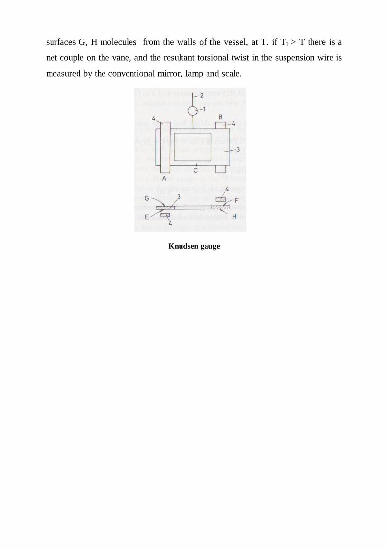
٤٠
surfaces G, H molecules from the walls of the vessel, at T. if T1 > T there is a
net couple on the vane, and the resultant torsional twist in the suspension wire is
measured by the conventional mirror, lamp and scale.
Knudsen gauge
٤١
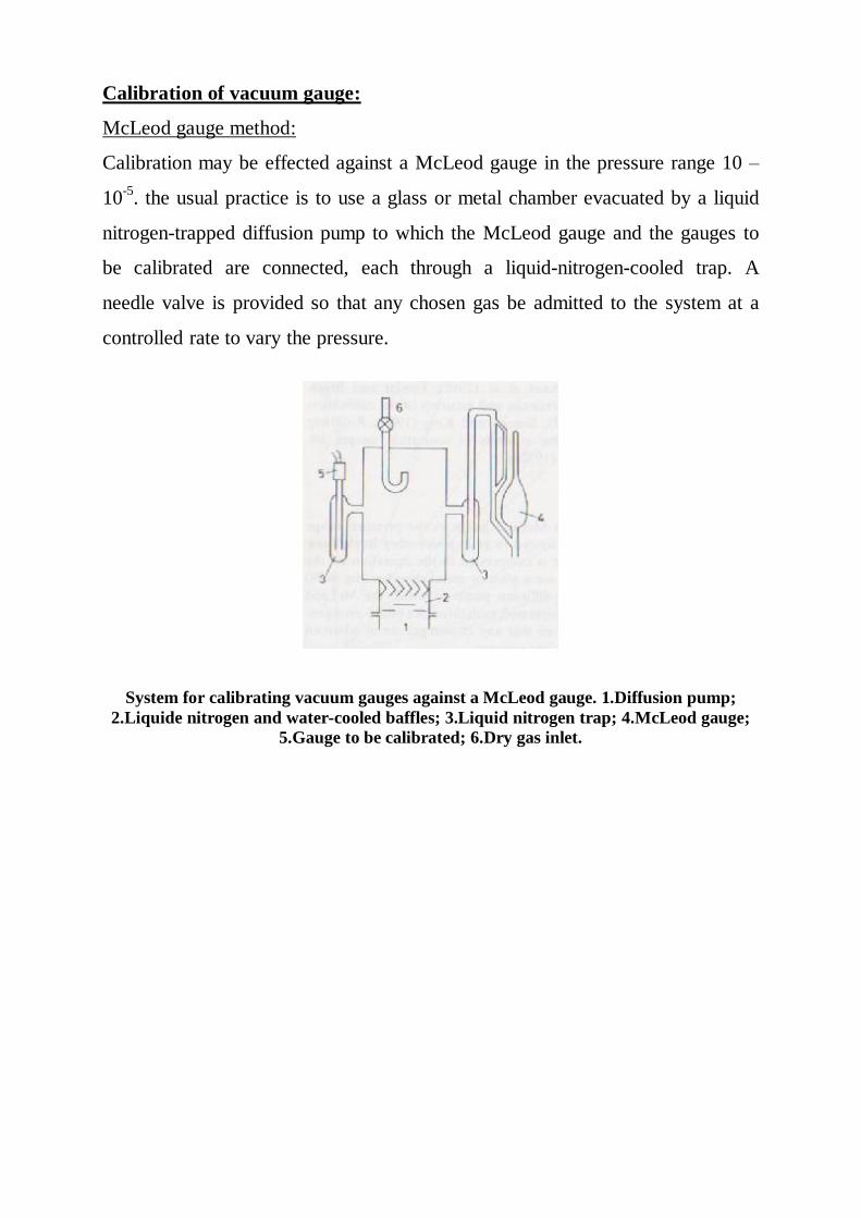
Calibration of vacuum gauge:
McLeod gauge method:
Calibration may be effected against a McLeod gauge in the pressure range 10 –
10-5. the usual practice is to use a glass or metal chamber evacuated by a liquid
nitrogen-trapped diffusion pump to which the McLeod gauge and the gauges to
be calibrated are connected, each through a liquid-nitrogen-cooled trap. A
needle valve is provided so that any chosen gas be admitted to the system at a
controlled rate to vary the pressure.
System for calibrating vacuum gauges against a McLeod gauge. 1.Diffusion pump; 2.Liquide nitrogen and water-cooled baffles; 3.Liquid nitrogen trap; 4.McLeod gauge;
5.Gauge to be calibrated; 6.Dry gas inlet.
٤٢
High vacuum technology:
General:
For the construction of vacuum systems or vacuum devices it is conventional to
use metals, glasses, ceramics, and some rubbers and plastics. The materials that
become part of the vacuum system, forming the enclosure (vessels, pipes) must
have sufficient mechanical strength to withstand the pressure difference, must be
impermeable enough to gases, must have low vapour pressures, and good
resistance to special working conditions.
Mechanical strength:
Vacuum enclosure are made up from cylindrical, plane and hemispherical
parts. All these parts tend to deform inward as a result of the difference between
external (atmospheric) and internal pressures. Cylindrical parts tend to collapse
easier if their length is greater than the critical length Lc defined by
Lc = 1.11D(D/h)1/2
Where D is the mean diameter and h the wall thickness.
Permeability to gases:
The metallic, glass or rubber of vacuum vessels or pipes are more less
permeable to gases. The quantity of gas which permeates the walls can be really
large as in the case of porous ceramics or casting or low as for the case of gas
diffusion through " non-porous" walls.
Vapour pressure and gas evolution:
The materials used in vacuum systems should have a low vapour pressure at
the maximum working temperature. Some metals (Zn, Cd, Pb) have at 400-500C
vapour pressures exceeding the pressures required in high vacuum system and
therefore these metals (or their alloys) cannot be used. For ultra-high vacuum
work the choice of metals is only stainless steels, high nickel alloys. The gas
evaluation from the metal surface should be low. To meet this requirement
٤٣
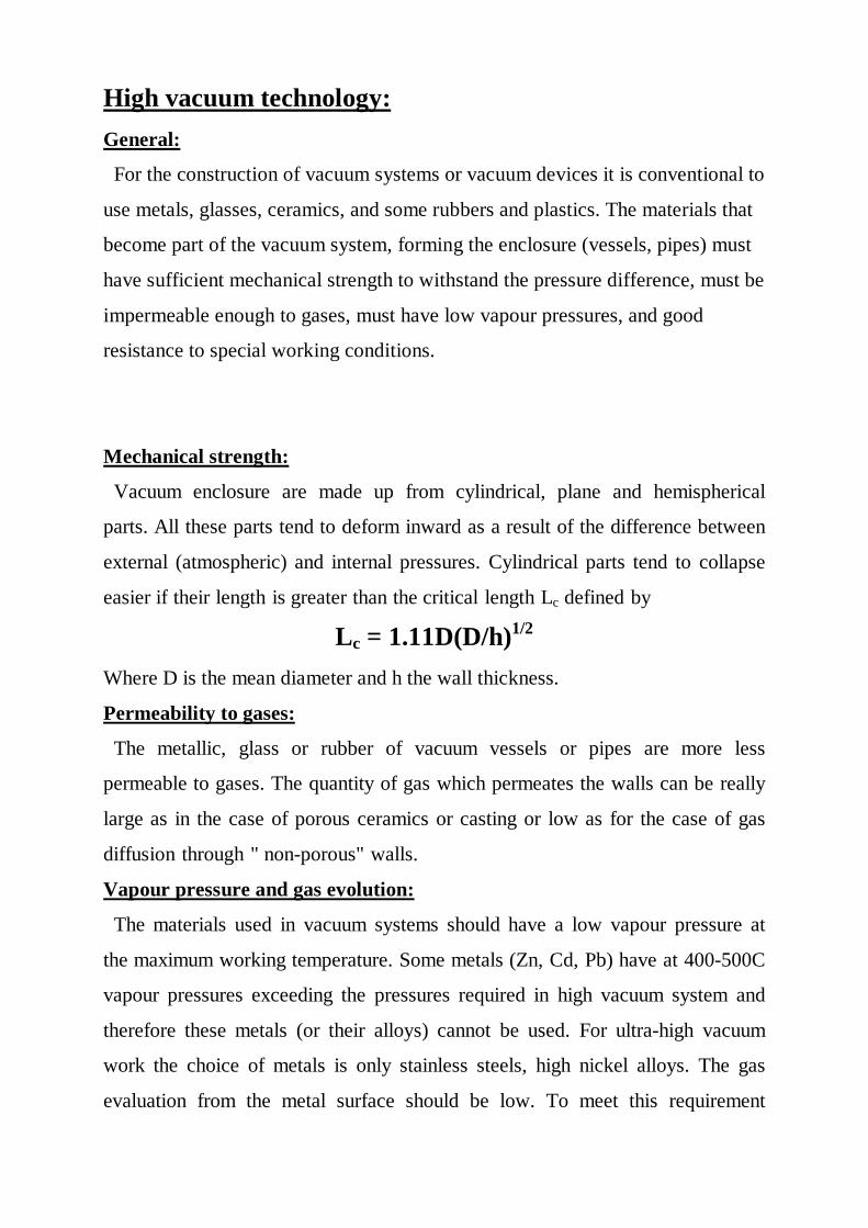
previously degassed materials are recommended, and the outgassing rate should
be decreased by cleaning and baking.
Useful range of materials for vacuum vessels and pipes Glass vessels and pipes:
Glass is used as the envelope of many vacuum devices (lamp, electron tubes),
as bell jars in small evaporation plants, as reaction vessels and connection pipes,
and in the construction of some diffusion pumps and gauges. The vacuum range
covered by glass is quite large. If the glass is exposed to steady temperature
differences between the two faces, thermal gradients are developed through the
glass. These are even more dangerous to the integrity of the glass than sudden
cooling.
Cleaning techniques:
Cleaning generally means the removal of undesirable materials lying on the
surface. In vacuum technology, the cleaning must be regarded not only as the
٤٤
removal of the visible dirt from the surface, but including the subsequent
removal of all the contamination physically stuck on the surface (oil, grease,
dust) or resulting from a chemical reaction (oxides, sulphides). The degree of
cleanliness must be higher, for higher vacuum. The oxides and other similar
surface layers can be removed by mechanical and / or chemical methods, as
abrasive blasting, wire brushing or pickling and etching.
٤٥
٤٦
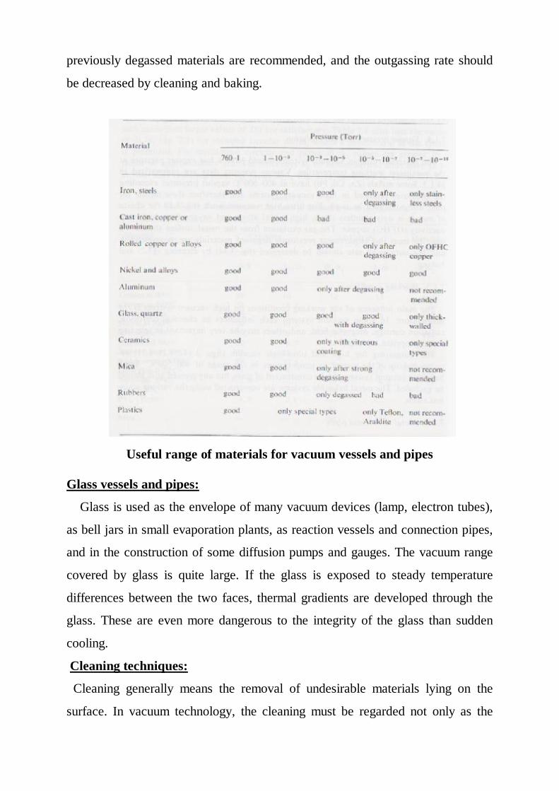
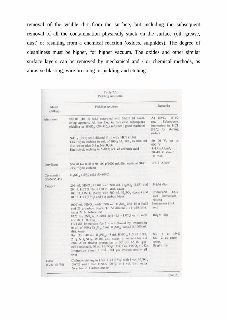
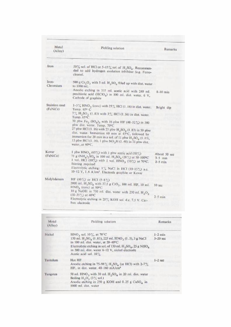
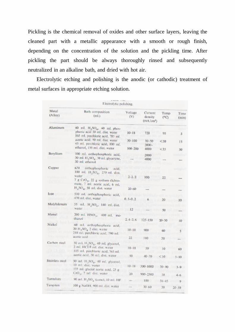
Pickling is the chemical removal of oxides and other surface layers, leaving the
cleaned part with a metallic appearance with a smooth or rough finish,
depending on the concentration of the solution and the pickling time. After
pickling the part should be always thoroughly rinsed and subsequently
neutralized in an alkaline bath, and dried with hot air.
Electrolytic etching and polishing is the anodic (or cathodic) treatment of
metal surfaces in appropriate etching solution.
٤٧
Cleaning of glass:
The glass may have rough appearance due to weathering or to devitrification.
Weathering is a result of the influence of the atmospheric vapour, and consists
of the hydrolysis of the alkali silicates, forming alkali hydroxides and colloidal
silicic acid. The alkali hydroxides react with the carbon dioxide from the air,
forming a film of alkali carbonates, with separation of silica. Due to this process
the glass loses its transparency and becomes brittle.
Glass vessels and pipes (new or weathered) can be washed by immersing
them in hydrochloric acid solution (1 – 5%) for 3 – 10 sec, followed by a
subsequent rinsing in water (40 – 50 ºC) and drying.
Chromic acid is satisfactory for cleaning glass (subsequent to a washing in
water). The usual cleaning solution known as chromic acid contains about 50 ml
of saturated aqueous sodium dichromate in a liter of concentrated sulphuric acid.
The chromic acid solution should be used only if it has its brown color. If the
color is changed the solution is decomposed.
A solution which is much more effective than the chromic acid solution
consists of 5% HF with 35% HNO3 in 60% water.
Acetone or alcohol may also be useful for drying glass parts.
Cleaning of ceramics:
Suitable cleaning of ceramic parts is obtained by firing the ceramic parts in air
at 800 – 1000 ºC. alternatively an alkaline cleaning solution can be used,
followed by immersion in dilute nitric acid (2 – 5 min). chromic acid or other
glass cleaning solution are also satisfactory.
Cleaning of rubber:
The rubber must be cleaned with a solution of KOH (20%) at 70 ºC with
subsequent washing with distilled water and drying with clean air, and/or
degassing in vacuum at 70ºC for 4 – 5 hours.
٤٨
Baking:
The most efficient method of reducing the out gassing rates of the parts of
vacuum systems is their baking. The useful rang of baking temperature is 400 –
500 ºC (for metal or glass systems), and the efficiency is much reduced if only
150 – 200 ºC is used .
Thin Film Deposition Processes
Thin film coatings provide enhanced optical performance on items ranging from
camera lenses to sunglasses. Architectural glass is often coated to reduce the
heat load in large office buildings, and provide significant cost savings by
reducing air conditioning requirements. Microelectronics as we know them
today would not be possible without vacuum technology. Microcircuits
fabricated in multi-step vacuum processes are used in devices ranging from
wrist watches to microwave ovens to automobile ignition and monitoring
systems. The computer industry would not exist if it were not for vacuum
technology. In 1990 the world market for integrated circuits was $50 billion; and
for the electronic devices which rely on these microcircuits, $0.9 trillion.
Decorative coatings applied to jewelry and plumbing fixtures is another large
industry based upon vacuum technology. Many of the components of plumbing
fixtures are manufactured by depositing thin films of chromium onto injection
molded plastic parts. The useful life of tool bits has also been increased by the
application of thin films that are chemical compounds. Tool steel cutting tools
used in lathes and mills are often coated with the chemical compound titanium
nitride to reduce wear of the cutting edges. The deposition of thin films
composed of chemical compounds may be performed in several ways. Co-
deposition is a technique in which vapors of two different materials are
generated simultaneously. These two vapors condense together, forming an
alloy or compound. Other techniques for deposition of compounds include
thermal evaporation of the compound (as is performed for salt coatings),
sputtering of the compound, and reactive sputtering or evaporation. In the
٤٩
reactive processes, atoms of the evaporant (typically a metal) chemically react
with gas species which are intentionally injected into the process chamber. Each
of these processes will be described in detail.
Thin Film Deposition in a Vacuum Environment
The techniques for thin film deposition have evolved in approximately
this order: thermally induced evaporation (by electrical resistance heating,
induction heating, and electron beam heating), sputtering (diode, triode,
magnetron, ion beam), arc processes, and most recently, laser ablation. In
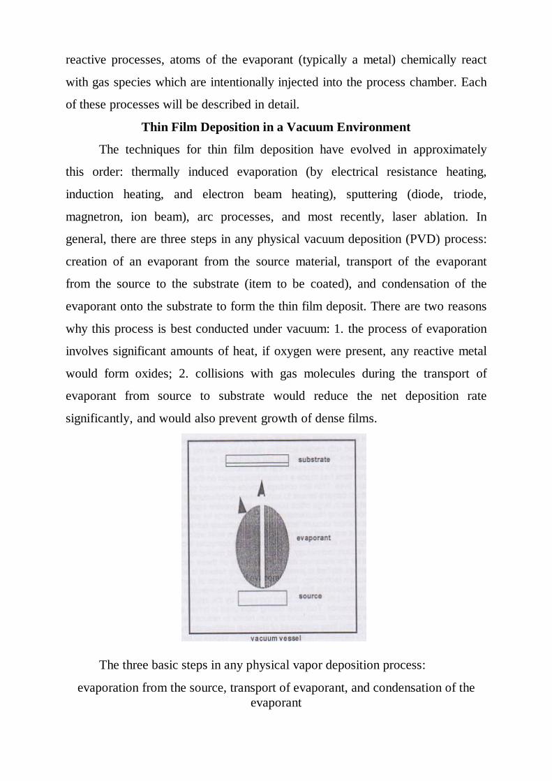
general, there are three steps in any physical vacuum deposition (PVD) process:
creation of an evaporant from the source material, transport of the evaporant
from the source to the substrate (item to be coated), and condensation of the
evaporant onto the substrate to form the thin film deposit. There are two reasons
why this process is best conducted under vacuum: 1. the process of evaporation
involves significant amounts of heat, if oxygen were present, any reactive metal
would form oxides; 2. collisions with gas molecules during the transport of
evaporant from source to substrate would reduce the net deposition rate
significantly, and would also prevent growth of dense films.
The three basic steps in any physical vapor deposition process:
evaporation from the source, transport of evaporant, and condensation of the evaporant
٥٠
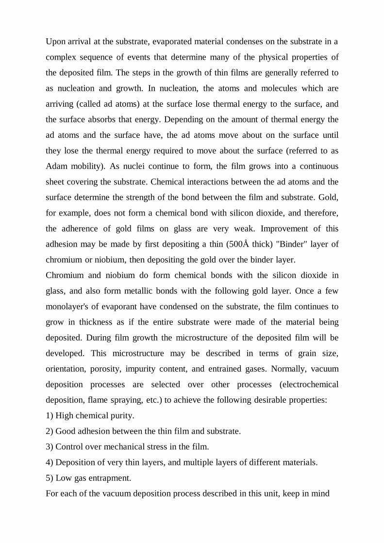
Upon arrival at the substrate, evaporated material condenses on the substrate in a
complex sequence of events that determine many of the physical properties of
the deposited film. The steps in the growth of thin films are generally referred to
as nucleation and growth. In nucleation, the atoms and molecules which are
arriving (called ad atoms) at the surface lose thermal energy to the surface, and
the surface absorbs that energy. Depending on the amount of thermal energy the
ad atoms and the surface have, the ad atoms move about on the surface until
they lose the thermal energy required to move about the surface (referred to as
Adam mobility). As nuclei continue to form, the film grows into a continuous
sheet covering the substrate. Chemical interactions between the ad atoms and the
surface determine the strength of the bond between the film and substrate. Gold,
for example, does not form a chemical bond with silicon dioxide, and therefore,
the adherence of gold films on glass are very weak. Improvement of this
adhesion may be made by first depositing a thin (500Å thick) "Binder" layer of
chromium or niobium, then depositing the gold over the binder layer.
Chromium and niobium do form chemical bonds with the silicon dioxide in
glass, and also form metallic bonds with the following gold layer. Once a few
monolayer's of evaporant have condensed on the substrate, the film continues to
grow in thickness as if the entire substrate were made of the material being
deposited. During film growth the microstructure of the deposited film will be
developed. This microstructure may be described in terms of grain size,
orientation, porosity, impurity content, and entrained gases. Normally, vacuum
deposition processes are selected over other processes (electrochemical
deposition, flame spraying, etc.) to achieve the following desirable properties:
1) High chemical purity.
2) Good adhesion between the thin film and substrate.
3) Control over mechanical stress in the film.
4) Deposition of very thin layers, and multiple layers of different materials.
5) Low gas entrapment.
For each of the vacuum deposition process described in this unit, keep in mind
٥١
the ultimate goal is to provide a means for depositing a thin film having the
required physical and chemical properties. The parameters one can control to
achieve the specified goals are:
1) Kinetic energy of the ad atoms.
2) Substrate temperature.
3) Deposition rate of the thin film.
4) Augmented energy applied to the film during growth.
5) Gas scattering during transport of the evaporant.
By varying these parameters one can generate thin films of a given material that
have different mechanical strength, adhesion, optical reflectivity, electrical
resistivity, magnetic properties and density.
Thermally Induced Evaporation
In this process, heat is input into the source material (often called the charge) to
create a plume of vapor which travels in straight-line paths to the substrate.
Upon arrival at the substrate, the atoms, molecules, and clusters of molecules
condense from the vapor phase to form a solid film. The heat of condensation is
absorbed by the substrate. On a microscopic scale the localized heating from this
process can be enormous. It is common, in the development of metal coating
techniques for thin cross-section plastic parts, to melt substrates during the
initial deposition runs. With experience, one can select source-to-substrate
distances and deposition rates which will allow coating of temperature sensitive
substrates without melting. There are several methods by which heat can be
delivered to the charge to cause vaporization: electric resistance heating,
induction heating, and electron beam heating. Deposition of thin films by laser
ablation and cathodic arc could be grouped in this section with thermal
processes, but there are some unique characteristics of these techniques which
are beyond the simple model of thermally induced evaporation. For this reason
we will cover these two deposition techniques separately.
٥٢
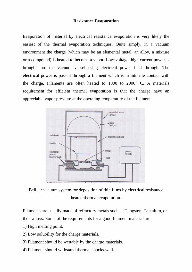
Resistance Evaporation Evaporation of material by electrical resistance evaporation is very likely the
easiest of the thermal evaporation techniques. Quite simply, in a vacuum
environment the charge (which may be an elemental metal, an alloy, a mixture
or a compound) is heated to become a vapor. Low voltage, high current power is
brought into the vacuum vessel using electrical power feed through. The
electrical power is passed through a filament which is in intimate contact with
the charge. Filaments are often heated to 1000 to 2000° C. A materials
requirement for efficient thermal evaporation is that the charge have an
appreciable vapor pressure at the operating temperature of the filament.
Bell jar vacuum system for deposition of thin films by electrical resistance
heated thermal evaporation.
Filaments are usually made of refractory metals such as Tungsten, Tantalum, or
their alloys. Some of the requirements for a good filament material are:
1) High melting point.
2) Low solubility for the charge materials.
3) Filament should be wettable by the charge materials.
4) Filament should withstand thermal shocks well.
٥٣
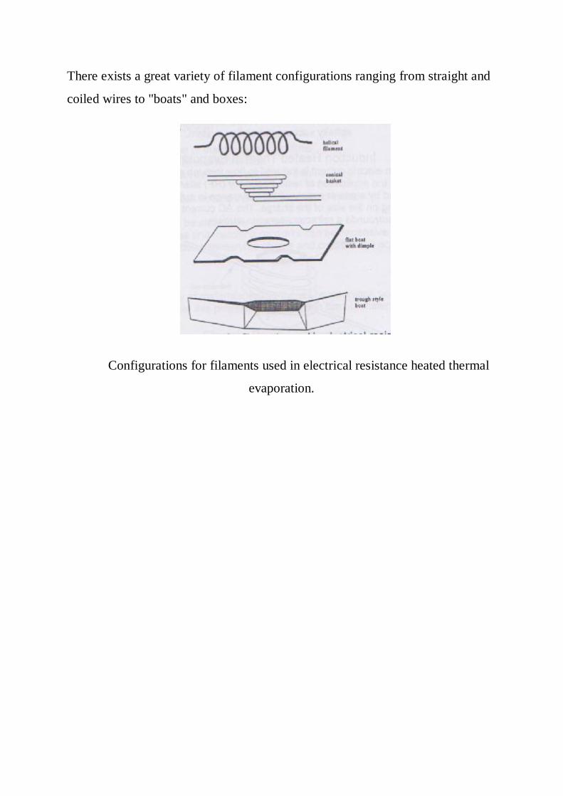
There exists a great variety of filament configurations ranging from straight and
coiled wires to "boats" and boxes:
Configurations for filaments used in electrical resistance heated thermal
evaporation.