Embed Size (px)
Citation preview
A MONTHLY DIGEST OF RADIO AND ALLIED MAINTENANCE
r MARCH
1940
_--6SK7 -6--A--8 -
THESE C AB L ES
R -F tDET.&OSC_ ARE BouroKBR ETHER
3000 BY A BLPCA ED
a COVER yE BACK VIEW
OF P
DOUBLE ÇOPSHR LpACER
BROWN _____-- .01 -Volume Gontrol
0., I
o., II
= I
7,--
xl
G) ' I 0.5Mfd.
60OV. _
I Each 1 7 Solenoid = = r A" GABLE
Push -bu Dial Lomas____J OSG1at01' Swi tch Con-act - compensated
era ure instantaneous
s esker and feather touch em
This two -unit head and ñadio
receiver
rps dash mount) _ push-button tuning. (See pcge 5.)
AUTO RADIO PAGE 5
RADIO - TELEVISION www.americanradiohistory.com
- - -,- ,...,..,. ,
----_._-_.._ _
MILLIONS 9 4 TROUt!!LONG LIP!
fMALLORY` ïsC$rax»s
V1811.T01% Ov1Dg .< Cars
Insta on A111940 Passeng
and Rodio
kfajigMr 9«4ioK need!
4P4i
* Up-to-the-minute accurate vibrator replacement chart for all makes and models of auto radio and battery - operated household receivers.
* Complete cross-reference of Mallory Vibrators by make and model of receiver.
* Practical vibrator servicing and testing information with 'scope pictures.
* Auto radio installation and interference elimination in all 1940 model cars.
* Vibrator connection charts.
P. R. MALLORY & CO., Inc. INDIANAPOLIS,
Use
MALLORY REPLACEMENT
CONDENSERS....VIBRATORS
Use
A)triEY REPLACEMENT
VOLUME CONTROLS
sPME
eel' 1(1' ci
You can save time and money on every auto or battery -operated household radio service job with this Mallory Replacement Vibrator Guide. Don't put off getting your copy. You'll say it is indispensable.
INDIANA Cable Address-PELMALLO
www.americanradiohistory.com
In1eLD ümeteceis e00 ° `° o. CCINMDMI ° AI mmume
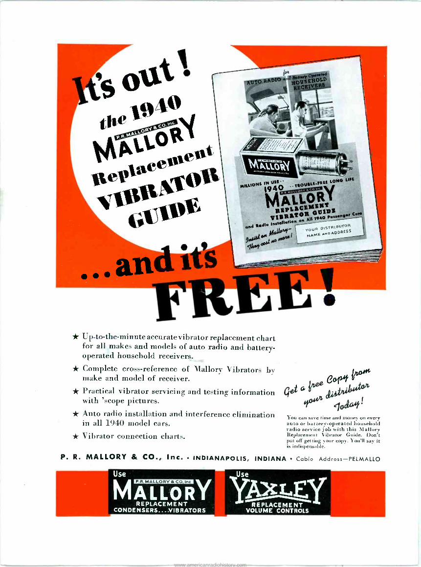
P tie Who Spsalea $500,000
Expended For Development, Backs Our Slogan
SPEAKER MADE IN ALL THE WORLD NO FINER
* HIGH POWER handling ability in these speakers has been provided through careful
design consideration of distortion elements, voice coil heat dissipation, and cone structure.
akers for tFREQUENYeneral applica -
ions. The designfeaturresSprohde full!st true, lowe notes einstead r
Ideal frequently
encountered, and excellent high frequency definition for voice reproduction.
* HIGH EFFICIENCY is obtained through quality Feralnic magnet structures and good
voice coil space factor. * RIBBON WIRE-ACIM voice coils on heavier units.
* POLYFIBROUS CONES -MOISTURE PROOF CENTERING assure permanent quality
and dependability. * RUST PROOF -DUST PROOF.
Cone Undistorted Undistorted Peak Voice Voice Coil Coil
Wt. List Price
Housing Peak Normal Watts Dia. Ohms Type Dia. Watts Watts
No. 31/2 ' 6-8 70 $115.0
PM -15-28 15" 38 28 6-8 58 65.00
PM -15-28 15" 28 15
33 2 6-8 20 30.00
15" 18 15 23 11/2" 6-8 30 40.00
PM -I5-1816 27.5000 PM-12-28 12"4" 28 21 293
11/2"6-8 PM -12-1 12" 18 15 21 11/4" 6-8 II 18.50
PM -12-16 12" 16 13 6-8 8 12.50
12" 13 10 18 I" 10 15.50 PM -10-13 18 11/4" 6-8
PM -I0-14 101/2" 14 I" 6-8 7 10.00
PM -10-12 101/2" 12 7 14 I" 6-8 6 8.50
PM -I0-10 101/2" 10 I" 6-8 6 8.50
8" II 8 6-8 5 6.75 PM -8-1 I6
6 6.75 PM -8-9 61/2, 9 7 13
I"34"
6-8 61/2 4.250
PM -6-9 61/2"
5 11 N 4 4.00 PM -6-7 5 3 8 3/4
PM -5-5
STANDARD UNIVERSAL
MATCHING TRANSFORMERS Volee Voice List ConePeak
Norm. Power Field Field Field Coll Coll Wt. Universal primary Transformers are
enHag
Und. Und. Peak Ohms Watts Dia. Ohms Lbs. Prise
tapped to accommodate all popular Type Dia. Watts Watts Watts Voltage 6-$ 7$ $95.00 tubes. Ne I I OV. DC 300 35/50 31/2"
PE -18-40 40 35 46 1 6-8 88 120.00
TypeNoPak Watts Pricet PA 1640 18" 40 35 45 110V. AC
350 22/35 3 2" 6-8 60 60.00 Peak
4ts
18" 30 25 40 110V. DC
31/2" 6-8 70 80.00 ST -I up to 51.50 PE -I8-30 18" 40 110V. AC ST -2 up 6 1.75
PE -I5 -25A 8-30 1$,"
25 20 30 1 I OV. DC 850 14/21 11/2" 6-8 28 26.50
S uptols 2.75 PE -15-25A 15" 2500 14/21 11/2" 6-8 28 26.50 ST -4T_5
up to zs 3.so PE -15-25B 15" 25 20 30 10V. DC 350 22/35 21/2" 6-8 40
16.7535.00 0 0 PE -13-30 131/4" 30 25 35
110V. DC 1000 14/21 11/2' 6-8
Universal line matching provide pri20 15 25 2500 14/21 11/2" 6-8 20 16.75
nary impedances at 500, 1000. 1500 PE -12-20A 12" 2010.50 Doms. PE -12-206 12" 15 25
100 10/15 11/4" 6-8 12
PE -12-16A 12" 16 13 21 110V. DC 2500 10/15 11/4" 6-8 1I 10.50
Type Undistorted List PE -12-168 12" 16 13 21 6-8 10 9.00
No. Peak Watts Price PE -10-12A 101/2" 12 10 16 110V. DC
16 2500 8/12 I" 6-8 10 9.00
PE -10 -12B8 18" 12 I8 14 110V. DC 1000 8/12 I" 6-8 8
7.00 7. 0
PE -8-10A 8" 2500 8/12 I" 6-8 8
PE -ß-106 8" 10 8 14
ST -6 up to 4 51.00 ST -7 up to 6 1.50 ST -8 up to 10 2.25 ST -9 up to 15 2.75 ST -10 upto25 3.50
UNITED TELETONE CORP. 1 5 0 VARICK STREET * NEW YORK, N. Y.
EXPORT DIVISION: I 0 0 VARICK STREET NEW YORK, N. Y. CABLES: "ARLAB''
SERVICE, MARCH, 1940 1
www.americanradiohistory.com
VOL.9,NO.3 - MARCH, 1940 SERVICE ROBERT G HERZOG, Editor A Monthly Digest of Radio and Allied Maintenance
Reg.
WE WOULD like to know how you made good, in your own words. That's the general idea
behind the "Service success Contest" announced in this issue. Prizes are of- fered for the twelve stories which the judges find of greatest merit. Literary style is not necessary, just real ideas proved successful by practical everyday application. Every bonafide Service Man is eligible.
Don't put it off . . . the contest closes May 15. And, don't forget to include a photograph of your store front or work bench.
RECENT U. S. Census figures show that over 80 percent of all Ameri- can families own at least one car;
more than four out of every five... .
What a potential field for auto -radio sales and service!
And, as we have pointed out repeated- ly in these columns, you are the most logical person to sell auto -radio re- ceivers. Your customer invites you into his home and seeks your advice. Simple to turn the conversation to auto -radio. Just ask him how the set in his car is work- ing. If he has one, its just as well- you've another service prospect. If he has none, sell him one.
BY TODAY'S standards sound equip- ment manufactured only three years ago is almost antique. Im-
provements in efficiency, quality, ease of operation and dependability have come so rapidly that only systems in- stalled very recently can be considered adequate. Prices, too, have been low- ered with the result that the ultimate purchaser can now get considerably more for his dollar than ever before.
In your own community there are un- doubtedly many pieces of sound equip- ment that are limping along on their last legs. Conduct a canvass among these installations and stage demonstra- tions to show the superiority of modern equipment. A large replacement mar- ket is awaiting your sales effort.
THE wide awake Service Man can look forward to a tidy bit of business as a result of the Havana
Conference. Reallocation of station frequency assignments will probably be ordered by the FCC shortly. It is said that more than half of the stations in the United States will be affected. When reallocation comes, some 8 mil- lion push-button operated receivers will require resetting . . . not to mention the additional service work for which th's will provide an entree.
30, 38
Stewart -Warner Packard PA35110I, PA351102 (Stewart -Warner R3291C) Tuning
U. S. Patent Office
CONTENTS e
Amplifier Ratings. By John M. Borst... Pa14 Automatic Record Changer (Crosley 639)... 25 Automobile Grounded Battery Terminal Chart. 7
Auto Radio. By Henry Howard 5 Browning F -M Kit 17
Customer Psychology. By Walter Kenworth. 12 Dealer Cooperation. By Martin Francis I I
G. E. H639. By Allan Epstein 16 Television Speeds Up 21
Tubes 33, 41 Associations Auto Radio Automobile Grounded Battery Terminal Chart 7
Auto Radio. By Henry Howard 5 Book Reviews 27 Circuits Arvin RE54 Mixer Stage 8
Arvin RE60 R -F Stage Browning F -M Adapter Crosley A169 G. E. H639A-C and H639D-C.. GTC P Twin Power Motorola 26C Detector and Output. Motorola 26C7 Driver and Output.. Philco AR7 R -F and Mixer Radio City 414 Multitester RCA 9901 Tube Tester Modernization Kit Stewart -Warner Hudson SA40 (First Half) Front Stewart -Warner Hudson SA40 (Second Half) Stewart -Warner Packard PA333915, PA353832 (Stewart -Warner 3341)
8
17
7
16
36 5
5
10
36 32
Cover 10
Tuning 10 Stewart -Warner Packard PA351099. PA351100 (Stewart -Warner R327I,
R3271C) Tuning 6
3291, 6
Stromberg -Carlson 435, 455, 480 Antenna Connections.. 28 TravLer 621 R -F and Mixer 6
Truetone D1091, 6C14-3 6 Wells -Gardner 6C9 Production Changes 28 Zenith -Nash AC4289 (Zenith 6MN496) Driver and Output.. 5 Cover Diagram Auto Radio. By Henry Howard 5 Manufacturers and Highlights 34, 37, 39, 40, 42, 43 On the Job GTC P Twin Power 36 Phonograph Motors. By Porter Turner. 41 RCA 9901 Tube Tester Modernization Kit 32 Public Address Amplifier Ratings. By John M. Borst 14 Decibels vs. Watts Conversion Chart 15
Shopping for Amplifiers. By D. L. Elam and B. E. Phillipsen. 40 Service Helps (Case Histories) G. E. H639A-C, H639D-C. By Allan Epstein 16 RCA Governor Motors 28 Stromberg -Carlson 435, 455, 480. By J. E. Ward 28 Wells -Gardner 6C9. By Joseph K. Rose 28 Television Television Speeds Up 21 Test Equipment Oscilloscope Helps Sales. By Murray Orman. 19
Radio City 414 Multitester 36 RCA 9901 Tube Tester Modernization Kit 32
Copyright, 1940, Bryan Davis Publishing Co., Inc.
BRYAN S. DAVIS President
JAS. A. WALKER Secretary
Chicago Office: 608 S. Dearborn Street
C. O. Stimpson, Mgr. Telephone: Wabash 1903
Published Monthly by the
Bryan Davis Publishing Co.
Inc.
19 East 47th Street New York City
Telephone: PLaza 3-0483
PAUL S. WEIL Advertising Manager
A. GOEWSL Circulation Manager
Wellington, New Zealand: Tearo Book Depot
Melbourne, Australia: McGill's Agency
Entered as second-class matter June 14, 1932, at the Post Office at New York, N. Y., under the Act of March 3, 1879. Subscription price: $2.00 per year in the United States of America and Canada; 25 cents per copy. $3.00 per year in foreign countries; 35 cents per copy.
2 SERVICE, MARCH, 1940
OF THIS ISSUE OVER 11,000 COPIES
www.americanradiohistory.com
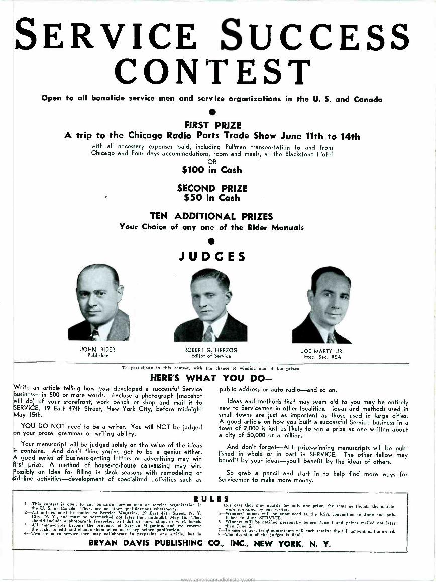
SERVICE SUCCESS CONTEST
Open to all bonafide service men and sery ice organizations in the U. S. and Canada
FIRST PRIZE A trip to the Chicago Radio Parts Trade Show June 11th to 14th
with all necessary expenses paid, including Pullman transportation to and from Chicago and Four days accommodations, room and meals, at the Blackstone Hotel
OR
$100 in Cash
SECOND PRIZE $50 in Cash
JOHN RIDER Publisher
TEN ADDITIONAL PRIZES Your Choice of any one of the Rider Manuals
JUDGES
ROBERT G. HERZOG Editor of Service
JOE MARTY, JR. Exec. Sec. RSA
To participate in this contest, with the chance of winning one of the prizes
HERE'S WHAT YOU DO- Wrire an article telling how you developed a successful Service business-in 500 or more words. Enclose a photograph (snapshot will do) of your storefront, work bench or shop and mail it to SERVICE, 19 East 47th Street, New York City, before midnight May 15th.
YOU DO NOT need to be a writer. You will NOT be judged on your prose, grammar or writing ability.
Your manuscript will be judged solely on the value of the ideas it contains. And don't think you've got to be a genius either. A good series of business -getting letters or advertising may win first prize. A method of house -to -house canvassing may win. Possibly an idea for filling in slack seasons with remodeling or sideline activities-development of specialized activities such as
public address or auto radio-and so on.
Ideas and methods that may seem old to you may be entirely new to Servicemen in other localities. Ideas and methods used in small towns are just as important as those used in large cities. A good article on how you built a successful Service business in a town of 2,000 is just as likely to win a prize as one written about a city of 50,000 or a million.
And don't forget-ALL prize-winning manuscripts will be pub- lished in whole or in part in SERVICE. The other fellow may benefit by your ideas-you'll benefit by the ideas of others.
So grab a pencil and start in to help find more ways for Servicemen to make more money.
RULES 1-This contest is open to any bonafide service man or service organization in
the U. S. or Canada. There are no other qualifications whatsoever. 2-All entries must be mailed to Service Magazine, 19 East 47th Street. N. Y. City, N. Y., and must be postmarked not later than midnight, May 15. They should include a photograph (snapshot will do) of store, shop, or work bench. 3-All manuscripts become the property of Service Magazine, and we reserve the right to edit and change them when necessary before publication.
4-Two or more service men may collaborate in preparing one article, but in
BRYAN DAVIS PUBLISHING
this case they may qualify for only one prize, the same as though the article were prepared by one writer.
5-Winners' names will be announced at the RSA convention in June and pub- lished in June SERVICE.
6-Winners will be notified personally before June 1 and prizes mailed not later than June 5.
7-In case of ties, tying contestants will each receive the full amount of the award. 8-The decision of the judges is final.
CO., INC., NEW YORK, N. Y.
www.americanradiohistory.com
4
175 JOBBERS Cad BE WRONG
When 175 of the Country's leading Radio Parts Distributors
come forward of their own volition and pay for the privi-
lege of adhering to a code of ethics of merchandising-
there must be a reason.
There is a reason-it's MORE PROFIT. These 175 far see-
ing Jobbers realize that the NRPDA has taken great strides
in its endeavor to remove destructive price competition; in
assisting to develop better understanding; in creating a
greater measure of goodwill, confidence and respect on the
part of Servicemen and Dealers.
They have found that cooperation with Dealers, Service-
men and other Members insures profits. You, too, will find
that the benefits which accrue after becoming a Member of
the NRPDA far outweigh the small cost of membership.
You can secure full information by addressing the Execu-
tive Secretary.
OFFICE OF THE EXECUTIVE SECRETARY
5 WEST 86th STREET NEW YORK, N. Y.
SERVICE, MARCH, 1940
www.americanradiohistory.com
RADIO SERVICE A Monthly Digest of Radio and Allied Maintenance
TELEVISION
AUTO RADIO THE trends of 1940 auto -radio re-
ceivers are toward more compact units; easier mounting; better
audio features, including more push-pull stages and more power output; broader i -f amplifiers; better station selecting systems, in the form of push-button improvements ; stabilized oscillators ;
ganged permeability tuning; more loctal tubes, higher -gain antenna -input cir- cuits, with more and better antenna filters ; single -ended tubes and the in- clusion of short-wave bands-to mention the more obvious.
List prices vary from $14.95 for sin- gle unit compacts to $69.95 for dual unit deluxe models. Many of the com- pacts mount in a space only 6 to 7 inches square usually on the steering column or under the dash. Mounting with a single bolt to the fire wall is featured in several instances.
Current drain varies widely; a four - tube Sonora draws only 3 amps while several models by Automatic are listed at 9 amps. Power output varies much more widely, ranging from 0.7 watt for the above Sonora to 10.5 watts for the highest priced Motorola. There is an unexplained lack of p -m speakers, Mo- torola being the only manufacturer us- ing them-and in only three of seven- teen models listed, although they are optional in several other models. Most of the electro -dynamic speakers used have four -ohm field coils which means over one and a half amperes dissipated. It would seem that battery economy might have been stressed as an impor-
By HENRY HOWARD
RECEIVER manufacturers, in gen- eral, have bent their every ef- fort to provide the utmost in
sensitivity and quality in their auto- radio receivers. Simple tuning, broad -band i-fs, simplified auto an- tennae and improved inputs are pre- ponderant among this year's models. The newer tube types, too, lend themselves to better and more com- pact designs.
In the next issue SERVICE will present a complete résumé in chart form, of practically every 1940 auto- radio receiver.
With automobile production for the first three months of 1940 ap- proaching the million and a half mark (output for February alone is esti- mated at close to half a million) the sales and service possibilities are immense.
.1,111,,,,1111111,,,,,,,,1,1111111 1,,,,,,,,,1111-11,,,1,1111,11111111111,,,,,,,,,,,,,11111111,,,,,,,,,,,,111111111,
tant sales feature. The r -f end of sets
shares of development, the audio end received
having had its it's about time some attention.
6Q7GT DET.-AMP.
AVC
.006 50
Meg.
-r+
6K6GT OUTPUT
N 3.0
BLUE
RE. .001 'Ri I{
. 000000o Y I
77w 27. 3
"rw" WHT
es Hum Sleeve., BLB o-
500 000,o Vol. Cont.
B+ t B E
'A* Hot <
O'j
4"-3 a qo BA65-
Tone Ste. -- y Fig.i 8+ El-
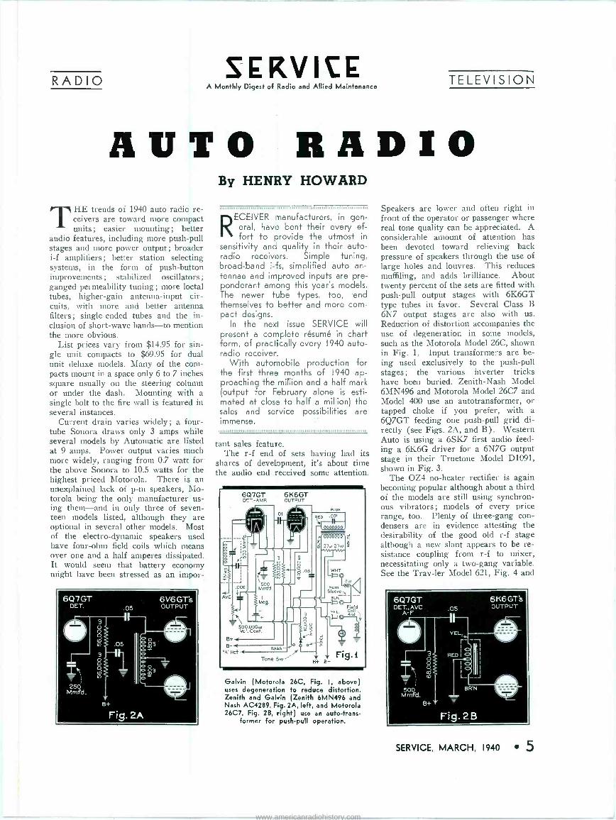
Galvin (Motorola 26C, Fig. I, above) uses degeneration to reduce distortion. Zenith and Galvin (Zenith 6MN496 and Nash AC4289, Fig. 2A, left, and Motorola 26C7, Fig. 2B, right) use an auto -trans-
former for push-pull operation.
Speakers are lower and often right in front of the operator or passenger where real tone quality can be appreciated. A considerable amount of attention has been devoted toward relieving back pressure of speakers through the use of large holes and louvres. This reduces muffiling, and adds brilliance. About twenty percent of the sets are fitted with push-pull output stages with 6K6GT type tubes in favor. Several Class B 6N7 output stages are also with us. Reduction of distortion accompanies the use of degeneration in some models, such as the Motorola Model 26C, shown in Fig. 1. Input transformers are be- ing used exclusively to the push-pull stages ; the various inverter tricks have been buried. Zenith -Nash Model 6MN496 and Motorola Model 26C7 and Model 400 use an autotransformer, or tapped choke if you prefer, with a 6Q7GT feeding one push-pull grid di- rectly (see Figs. 2A, and B). Western Auto is using a 6SK7 first audio feed- ing a 6K6G driver for a 6N7G output stage in their Truetone Model D1091, shown in Fig. 3.
The OZ4 no -heater rectifier is again becoming popular although about a third of the models are still using synchron- ous vibrators; models of every price range, too. Plenty of three -gang con- densers are in evidence attesting the desirability of the good old r -f stage although a new slant appears to be re- sistance coupling from r -f to mixer, necessitating only a two -gang variable. See the Trav-ler Model 621, Fig. 4 and
6Q7GT DET., AVC
A- F
IR 500
M mfd.
.05
VEL.
r - I
3 RED
ó I
I
10 L_ __J
BR'N
5+
Fig. 2B
6K6GT's OUTPUT
SERVICE, MARCH, 1940 5
www.americanradiohistory.com

NTENNA SOCYET
A
Í'111bj +
9 6SI(1
R.F.
c.
c
6SA7 IST DET-OS i.
+nGs
J./\"¡JWT
jj7O TANT'ONO, 10j
CS
OS
Fig.3
00
rC RAI
cl
G.
14 5T I.F.
=á>1 r_e .,r c i1 -c,, `...-
Te TAGES MEASURED UNDER FOLLOWING CONDITIONS
MTTERV VOLTAGE 0.3 AT TER.VNAl3. WNO, IN.0. POSITION
ANTENNA SHORTED TD CRASHS.
READINGS IN N.,, roartNNV.
ALL TAREN WITH MOP PER VOLT, K TER PLATE SCREEN GRID RR-TAGES READ CN SRDW ECKE.
AND ROWS,. COEN EETWEEN »CASE rmeeNAIs
6B8G ,.F. -2ND DU E A.V.C.
---ei il LOCAL OUNCE OMEN
Ty 2ND I.F.
A.
., 0.4.
Cto COS C2D
.00 YNf. I .
j.
CDNNECM1ONS QTEANK FELD
SAEANEII.
0
SKwN[ ̀/-YG I1t I Y,Gop
t I,. ,,E. lM
IJ p
.DR
8P:
K
tab
0.111. --e. i Cw a (TE
1
NN
Yf. ^ C6 C e ; .ca':,F. $ e4
roAWETdI ET till, _ FUSE Su ^T ON-OFF _ cyE 0.1p l,E -T* SWIiCN Yf. TSYf. = . T,YF. vORATOP
SOCRET
Nor CID -C4-566
1,+00 n
Western Auto (Truetone D1091, 6C14-3, Fig. 3 above) uses a 6SK7 audio, a
6K6G driver and 6N7G output.
the Crosley A169, Fig. 5. The Crosley also features Magnetune station selec- tion... .
The method of untuned coupling re- ferred to is more or less permissable in auto sets with their limited voltage picked up on auto antennas. In home sets, this stunt would give trouble with cross -modulation.
Pole antennas are becoming standard equipment, some with built-in, and others with optional filters and antenna boosters. Some manufacturers go so far as to say their sets will not per -
Stewart -Warner (Packard PA351099, PA351100, and Stewart -Warner R3271, R327IC, Fig. 6, below) provides a tapped
antenna input.
6 SERVICE, MARCH, 1940
6001 c. Ant. Adj
T Padder
Travier (Model 621, Fig. 4, left) em- ploys a resistance -coupled r -f stage.
form with high -capacity antennas, such as roof, built-in and under -running - board aerials. Others are more lenient, providing tapped antenna coils for matching various types. See Stewart - Warner Packard Model R3271C Fig. 6. Note also the single push type rotary switch tuning unit. A mute switch is located on the station selector switch. Another Stewart -Warner Packard Mod- el R3291 (Fig. 7) features a single push button with permeability -tuned os- cillator coils and, also, a muting switch. A three -gang permeability tuned unit is
Stewart -Warner (Packard PA35110I, PA351 102, Stewart -Warner 3291, R3291C, Fig. 7, below) features single button with permeability -tuned oscillator coils.
2100 MMFD.
ANT. COIL N
Fr¡
d
470 M u)
6SK7 0.r.
a
1 01 1500wa6 1500 i
A 10Mw/
33 M Eu
6A8 saFW
1st DEE osc.-
.0003
B+SCR.
o' 1 it TEMP ((e'er COMP
220M
22Mw-4- 3
Fig .7 r
B+ SCR TO AVC
TEMP COMP
.00039
7Ì
B+
www.americanradiohistory.com
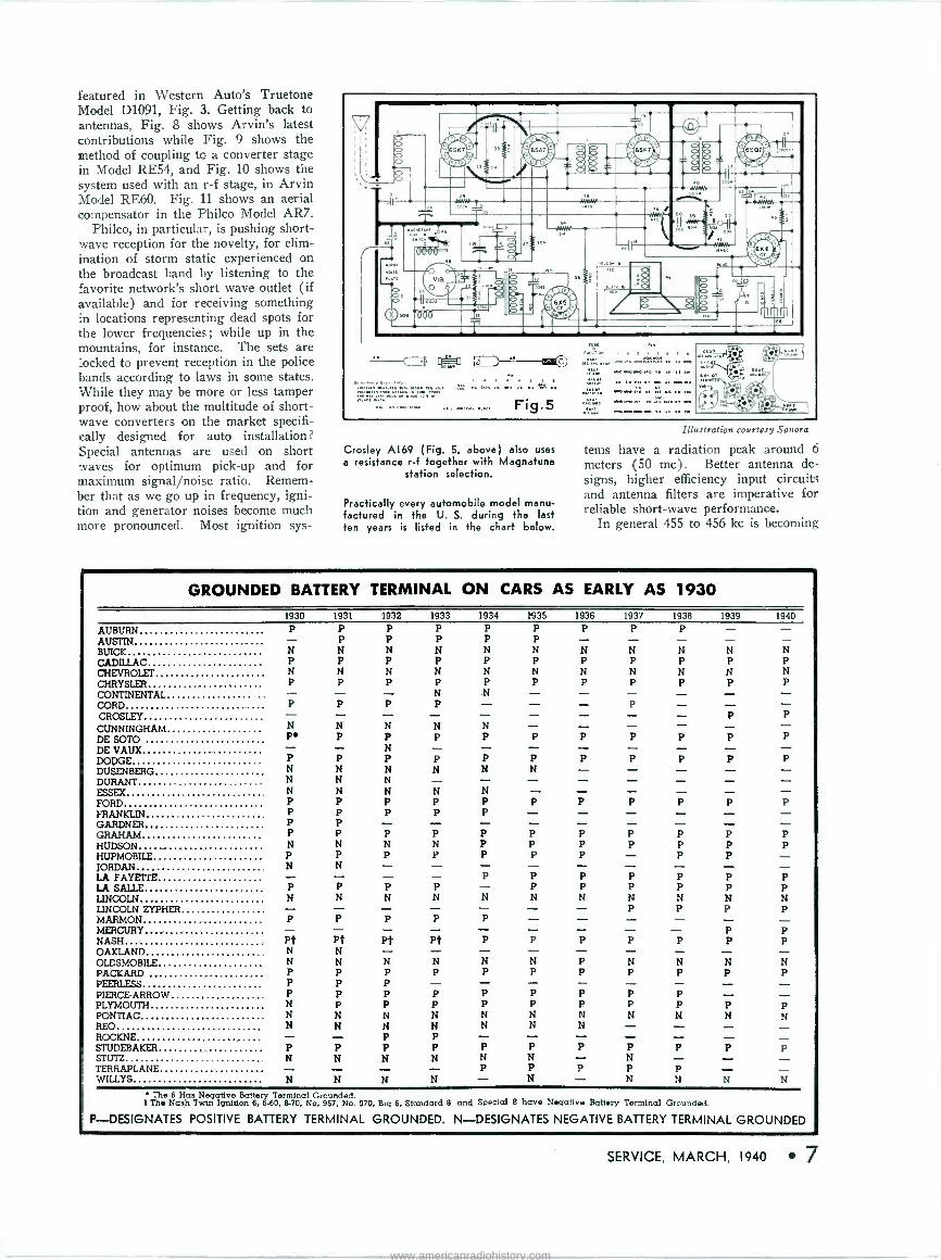
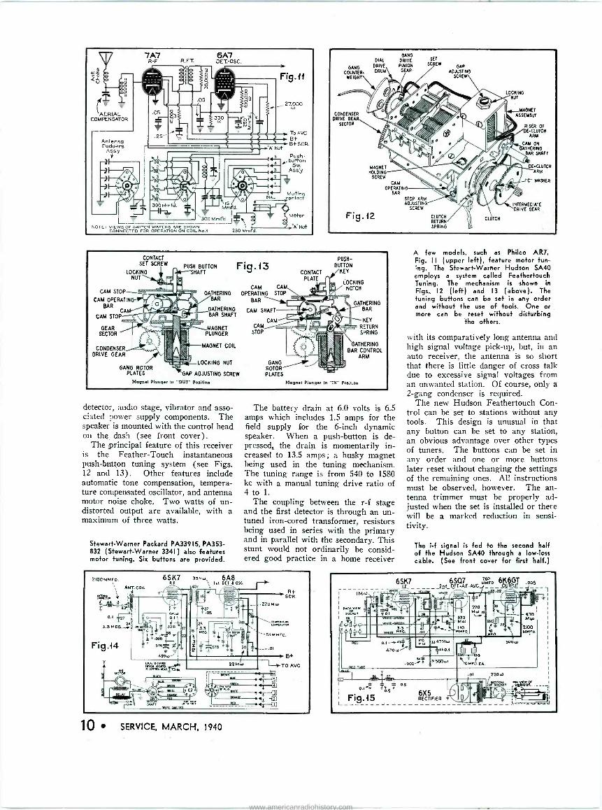
featured in Western Auto's Truetone Model D1091, Fig. 3. Getting back to antennas, Fig. 8 shows Arvin's latest contributions while Fig. 9 shows the method of coupling to a converter stage in Model RE54, and Fig. 10 shows the system used with an r -f stage, in Arvin Model RE60. Fig. 11 shows an aerial compensator in the Philco Model AR7.
Philco, in particular, is pushing short- wave reception for the novelty, for elim- ination of storm static experienced on the broadcast band by listening to the favorite network's short wave outlet (if available) and for receiving something in locations representing dead spots for the lower frequencies; while up in the mountains, for instance. The sets are locked to prevent reception in the police bands according to laws in some states. While they may be more or less tamper proof, how about the multitude of short- wave converters on the market specifi- cally designed for auto installation? Special antennas are used on short waves for optimum pick-up and for maximum signal/noise ratio. Remem- ber that as we go up in frequency, igni- tion and generator noises become much more pronounced. Most ignition sys-
lï
-- o,
O 4014 4170), 66N7 » p
16a p pr !ILô" ° t 24
iiu .Ìr «w_i2 vÑw .li;;Of
° ' ., °L °° z " . °. ' "ó"`[*'.'
o.:o. >.
a a ere> (1 'J`K 06x6 ÿ T - +010ì
,ÿ. evie.° > I R.
.s 8 .>°
1 5
0 'i ,o - ' 4..040. ' °°. " ..s F 6x3 H >
- A '
Qx .. oóo Lx p-` r.Ór° ñLnn r : - - - =`
=} > ,ear. ,..,.,...x..
....4044,_.... Fig.5 seo
Crosley A169 (Fig. 5, above) also uses a resistance r -f together with Magnatune
station selection.
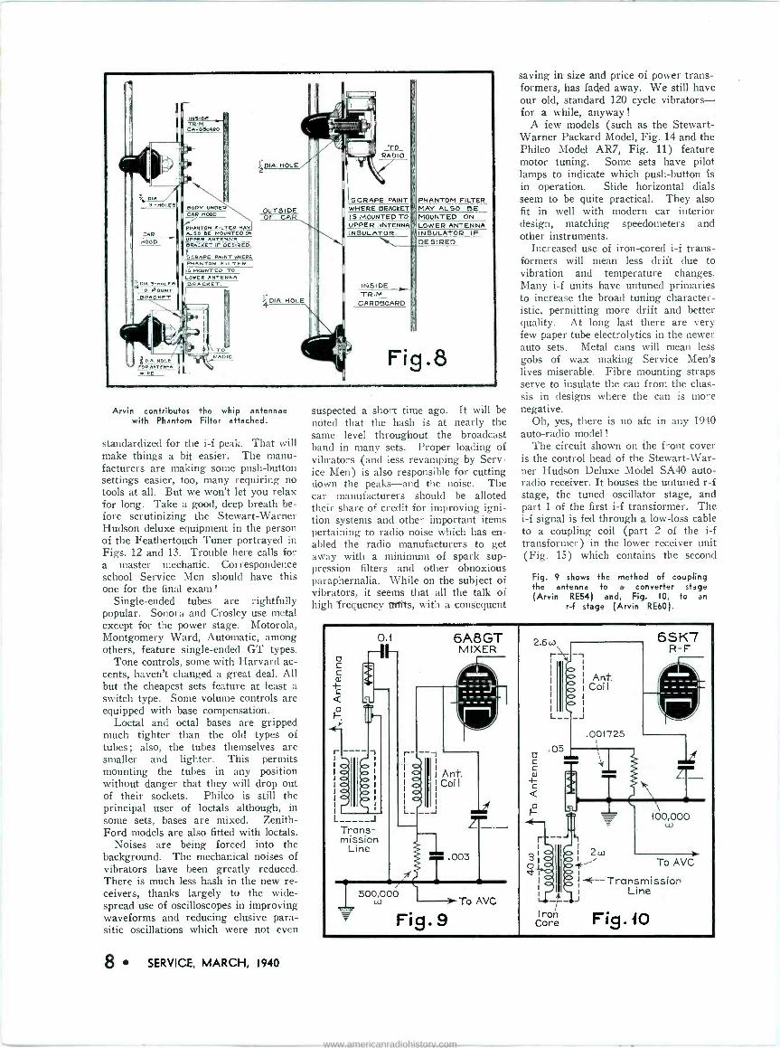
Practically every automobile model manu- factured in the U. S. during the last ten years is listed in the chart below.
Illustration courtesy Sonora
tems have a radiation peak around 6 meters (50 mc). Better antenna de- signs, higher efficiency input circuits and antenna filters are imperative for reliable short-wave performance.
In general 455 to 456 kc is becoming
GROUNDED BATTERY TERMINAL ON CARS AS EARLY AS 1930 1930
AUBURN P AUSTIN - BUICK N CADILLAC P CHEVROLET N CHRYSLER P CONTINENTAL CORD CROSLEY
CUNNINGHAM DE SOTO DE VAUX DODGE DUSENBERG DURANT ESSEX FORD P
FRANKLIN P GARDNER P GRAHAM P HUDSON N HUPMOBILE P JORDAN N LA FAYETTE - LA SAUE P LINCOLN N LINCOLN ZYPRER - MARMON P MERCURY - NASH Pt OAKLAND N
OLDSMOBILE N PACKARD P PEERLESS P
PIERCE -ARROW P PLYMOUTH N PONTIAC N REO N ROCKNE - STUDEBAKER P STUTZ N
WILLYS N TERRAPLANE
P
N P.
P N N N
1931
P P N P N P
P
N P
P N N N P P P P N P N
P N
P
Pt N N P P P P N N
P N
N
1932
P P N P N P
P
N P N P N N N P P
P N P
P N
P
Pt
N P P P P N N P P N
N
1933
P P N P N P N P
N P
P N
N P P
P N P
P N
P
Pt
N P
P P N N P P N
N
1934
P P N P N P N
N P
P N
N P P
P P P
P
N
P
P
N P
P P N N
P N P
1935 P P N P N P
P
P N
P
P P P
P P N
P
N P
P P N N
P N P N
1936 1937
P P
N N P P N N P P
- P
P P
P P
P P
P P P P P - P P P P N N - P
P P
P N P P
P P P P N N N - P P - N P P - N
1938 1939
P - N N P P P N N N P P P
- p P
P P P
P P P
P
P P P
P P N P
P
N P
P P N
P
P N
1940
N
P
P P
P P N P
P P
N P
P N
P
N
The 6 Has Negative Battery Terminal Grounded. t The Nash Twin Ignition 6, 6-60, 8-70, No. 967, No. 970, Big 6, Standard 8 and Special 8 have Negative Battery Terminal Grounded.
P-DESIGNATES POSITIVE BATTERY TERMINAL GROUNDED. N-DESIGNATES NEGATIVE BATTERY TERMINAL GROUNDED
SERVICE, MARCH, 1940 7
www.americanradiohistory.com
INSIDE TRM CAVDDOARD
DODS' UNDER CAR MOOD
PHANTOM FILTER MAY ALSO DE MOUNTED ON
UPPER ANTENNA QRACHET IF DESIRED.
SCRAPE PAINT WHERE PHANTOM FI LTER IS MOUNTED TO LOWER ANTENNA BRACKET.
TO RADIO
PA. HOLE FOR AHTEAHA
RE
DIA. HOLE
UTS IDE
DIA. HOLE
TO RADIO
SCRAPE PAINT WHERE BRACKET
I S MOUNTED TO UPPER :ANTENNA INSULATOR.
INSIDE TRIM
CARDBOARD
PHANTOM FILTER MAY ALSO BE MOUNTED ON LOWER ANTENNA INSULATOR IF DESIRED
Fig.8
Arvin contributes the whip antennae with Phantom Filter attached.
standardized for the i -f peak. That will make things a bit easier. The manu- facturers are making some push-button settings easier, too, many requiring no tools at all. But we won't let you relax for long. Take a good, deep breath be- fore scrutinizing the Stewart -Warner Hudson deluxe equipment in the person of the Feathertouch Tuner portrayed in Figs. 12 and 13. Trouble here calls for a master mechanic. Correspondence school Service Men should have this one for the final exam !
Single -ended tubes are rightfully popular. Sonora and Crosley use metal except for the power stage. Motorola, Montgomery Ward, Automatic, among others, feature single -ended GT types.
Tone controls, some with Harvard ac- cents, haven't changed a great deal. All but the cheapest sets feature at least a switch type. Some volume controls are equipped with base compensation.
Loctal and octal bases are gripped much tighter than the old types of tubes ; also, the tubes themselves are smaller and lighter. This permits mounting the tubes in any position without danger that they will drop out of their sockets. Philco is still the principal user of loctals although, in some sets, bases are mixed. Zenith - Ford models are also fitted with loctals.
Noises are being forced into the background. The mechanical noises of vibrators have been greatly reduced. There is much less hash in the new re- ceivers, thanks largely to the wide- spread use of oscilloscopes in improving waveforms and reducing elusive para- sitic oscillations which were not even
8 SERVICE, MARCH, 1940
suspected a short time ago. It will be noted that the hash is at nearly the same level throughout the broadcast band in many sets. Proper loading of vibrators (and less revamping by Serv- ice Men) is also responsible for cutting down the peaks-and the noise. The car manufacturers should be alloted their share of credit for improving igni- tion systems and other important items pertaining to radio noise which has en- abled the radio manufacturers to get away with a minimum of spark sup- pression filters and other obnoxious paraphernalia. While on the subject of vibrators, it seems that all the talk of high frequency units, with a consequent
saving in size and price of power trans- formers, has faded away. We still have our old, standard 120 cycle vibrators- for a while, anyway !
A few models (such as the Stewart - Warner Packard Model, Fig. 14 and the Philco Model AR7, Fig. 11) feature motor tuning. Some sets have pilot lamps to indicate which push-button is in operation. Slide horizontal dials seem to be quite practical. They also fit in well with modern car interior design, matching speedometers and other instruments.
Increased use of iron -cored i -f trans- formers will mean less drift due to vibration and temperature changes. Many i -f units have untuned primaries to increase the broad tuning character- istic, permitting more drift and better quality. At long last there are very few paper tube electrolytics in the newer auto sets. Metal cans will mean less gobs of wax making Service Men's lives miserable. Fibre mounting straps serve to insulate the can from the chas- sis in designs where the can is more negative.
Oh, yes, there is no afc in any 1940 auto -radio model !
The circuit shown on the front cover is the control head of the Stewart -War- ner Hudson Deluxe Model SA40 auto- radio receiver. It houses the untuned r -f stage, the tuned oscillator stage, and part 1 of the first i -f transformer. The i -f signal is fed through a low -loss cable to a coupling coil (part 2 of the i -f transformer) in the lower receiver unit (Fig. 15) which contains the second
Fig. 9 shows the method of coupling the antenna to a converter stage (Arvin RE54) and, Fig. 10, to an
r -f stage (Arvin RE60).
0.1 --IE-
SL
L J
Trans- mission
Line
/
r
0 0
6A8GT MIXER
Ant. Coil
.ßi..003
t 1 500,000 > To AVC
Fig. s
2.6u)
9 o
.05
r
Iron Core
65K7 R -F
100,000 w
2w I í To AVC 1F'
E --Transmission I Line J
Fig. 10
www.americanradiohistory.com
AMPERITEJImotuiced the eiccfsTAarAacE in the may, in ._9nception
GRADIENT
DynAmic UNI -DIRECTIONAL. NEW
SUPERIOR ELIPSOID PICKUP PATTERN
ELIMINATES FEEDBACK TROUBLE BECAUSE IT HAS LOWEST
IFFEEDBACK POINT OF ALL DIAPHRAGM TYPE MICROPHONES
FLAT RESPONSE. FREE FROM ANNOYING PEAKS, GIVING STUDIO -QUALITY REPRODUCTION.
8 The P.G. diaphragm follows air particle velocity where ' amplitude is a GRADIENT of the PRESSURE. In ordinary
dynamics amplitude is restricted from following air par- tide velocity. The P.G. DYNAMIC is a radical improvement in this type of microphone. You can actually hear the difference. Case is designed according to modern acoustic principles. Rugged, not affected by temperature, altitude or humidit t. HAS UNUSUALLY HIGH OUTPUT. -SS DB.
MODEL PGH (PGL, 200 ohms). Excellent for high fidelity P.A. installations. brcadcast studio, and professional recording. With switch, cable connector. 25' cable. Chrome finish. LIST 53.00 ( 4 0- 10 000 C.P.S. )
MODEL PGAH (PGAL. 200 ohms). For speech and music. 70.8000 C.P.S. Switch, cable connector, li' cable. Chrome. LIST $25.00
00 1000 0000
FLAT RESPONSE Oi I DYNAMIC
COMBINATION VELOCITY-)YNAMIC ACHIEVED WITH
ACOUSTIC COMPENSRTOR An exclusive Amperite feature: 13y mov- ing up the Acoustic Compensator you change the AMPERITE VELOCITY to a DYNAMIC microphone wit} out peaks. At the same time you reduce die back pick- up, making the microphone practically UNI -DIRECTIONAL.
WITH ACOUSTIC COMPENSATOR: MODEL RBHk; RBMk (204 ohms) with switch, cable connector.
Chrome_ LIST $42.00
RSHk; RBSk (200 ohms). Switch, cable connector, Acoustic Comp( nsator.
Chrome or Gunmeta . LIST $32.00
NRITE FOR FREE SALES AIDS AMPERITE (.
AMPERITE KONTAK MIKE Puts Musical Instruments Across
Ss beautiful is the one produced with the Kontak Mike, that it was used in the Philadelphia Symphony to amplify a mando in solo. Gives excellent results with any amplifier, radio sets, and record players. MODEL SKH (hi -imp) LIST $12.00 MODEL KKH, with hand volume control LIST 18.00 Plug extra List 1.50
FOOT PEDAL, for making beautiful crescendos LIST 12.00
5E 1 BROADWAY, N.Y. U.S.A.
SERVICE, MARCH, 1940 9
www.americanradiohistory.com
1 v Q1
Jr
Qli
AERIAL COMPENSATOR
Antenna Padders
A ss'y
R.FT. 6A7 DET.-OSC.
7A7 R -F
= º
390 Mmfd. aF
IR15 R Mmfd. ., 'T I
300Mmfd. R NOTE: VIEWS OF SWITCH WAFERS ARE SHOWN
CONNECTED FOR OPERATION ON COIL No.1 250 Mmfd.
-3
Fig.11
, 27,000 - w
i'A°Hot
To AVC Bt B+ SCR.
Push- y button
Sw. Assy
DIAL Muting ycontact Motor
"A"Hot
DIAL
GANG DRIVE
COUNTER- DRUM
WEIGHT
CONDENSER DRIVE GEAR
SECTOR
MAGNET HOLDING
SCREW
Fig.12
GANG DRIVE PINION GEAR
CAM OPERATING
BAR
STOP ARM ADJUSTING
SCREW
SET SCRE
CLUTCH RETURN SPRING
GAP ADJUSTING
SCRE
CLUTCH
LOCKING NUT
MAGNET ASSEMBLY
RISER OF
DE -CLUTCH ARM
CAM ON ATHERING
BAR SHAFT
DE -CLUTCH ARM
"C WASHER
INTERMEDIATE
DRIVE GEAR
CONTACT SET SCREW
CAM STOP
CAM OPERATING BAR
CAM CAM STOP
GEAR SECTOR
PUSH BUTTON LOCKING rSNAFT
NUT
CONDENSER DRIVE GEAR
GANG ROTOR PLATES
GATHERING BAR
GATHERING BAR SHAFT
MAGNET PLUNGER
MAGNET COIL
LOCKING NUT
GAP ADJUSTING SCREW
Magnet Plunger in "OUT" Position
Fig.13
CAM CAM
OPERATING STOP
BAR
CAM SHAFT
CAM CAM
STOP
ROTOR PLATES
CONTACT PLATE
PUSH- BUTTON
KEY
LOCKING NOTCH
G THERING BAR
KEY RETURN SPRING
GATHERING BAR CONTROL
ARM
Magnet Plunger in "IN" Position
detector, audio stage, vibrator and asso- ciated power supply components. The speaker is mounted with the control head on the dash (see front cover).
The principal feature of this receiver is the Feather -Touch instantaneous push-button tuning system (see Figs. 12 and 13). Other features include automatic tone compensation, tempera- ture compensated oscillator, and antenna motor noise choke. Two watts of un- distorted output are available, with a maximum of three watts.
Stewart -Warner Packard PA33915, PA353- 832 (Stewart -Warner 3341 ) also features motor tuning. Six buttons are provided.
The battery drain at 6.0 volts is 6.5 amps which includes 1.5 amps for the field supply for the 6 -inch dynamic speaker. When a push-button is de- pressed, the drain is momentarily in- creased to 13.5 amps ; a husky magnet being used in the tuning mechanism. The tuning range is from 540 to 1580 kc with a manual tuning drive ratio of 4 to 1.
The coupling between the r -f stage and the first detector is through an un - tuned iron -cored transformer, resistors being used in series with the primary and in parallel with the secondary. This stunt would not ordinarily be consid- ered good practice in a home receiver
2100 MMFD.
ANT. COIL
0.1
3.3 MEG. -4,
Fig.14
6SK7 33Mw 6A8 40'..
22Moi
B+ SCR.
-220MCi)
SI M MFD.
41;---12]
B+
TO AVC
10 SERVICE, MARCH, 1940
A few models, such as Philco AR7, Fig. II (upper left), feature motor tun- ing. The Stewart -Warner Hudson SA40 employs a system called Feathertouch Tuning. The mechanism is shown in
Figs. 12 (left) and 13 (above). The tuning buttons can be set in any order and without the use of tools. One or more can be reset without disturbing
the others.
with its comparatively long antenna and high signal voltage pick-up, but, in an auto receiver, the antenna is so short that there is little danger of cross talk due to excessive signal voltages from an unwanted station. Of course, only a 2 -gang condenser is required.
The new Hudson Feathertouch Con- trol can be set to stations without any tools. This design is unusual in that any button can be set to any station, an obvious advantage over other types of tuners. The buttons can be set in any order and one or more buttons later reset without changing the settings of the remaining ones. All instructions must be observed, however. The an- tenna trimmer must be properly ad- justed when the set is installed or there will be a marked reduction in sensi- tivity.
The i -f signal is fed to the second half of the Hudson SA40 through a low -loss cable. (See front cover for first half.)
IM ur. r
E9
6SK7 6SQ7 32.FD.6K6GT ' DOB
IF 2nd DET-AFAVCJ___02 OITPJT _
3.3- MEO.
o.l-i4 4T0w--"2'
1 .002-i
)l
ö 4
aw 0341 Mut
560w
220 MW Iq
330 Mal
110 MMFD
fO RFD. EA.
R-
rr
470 MEtl
2100 10 1AMFD MFD.
500W
.01
s
6X5 RECTIFIER
... vcw Or
www.americanradiohistory.com
DEALER COOPERATION By MARTIN FRANCIS
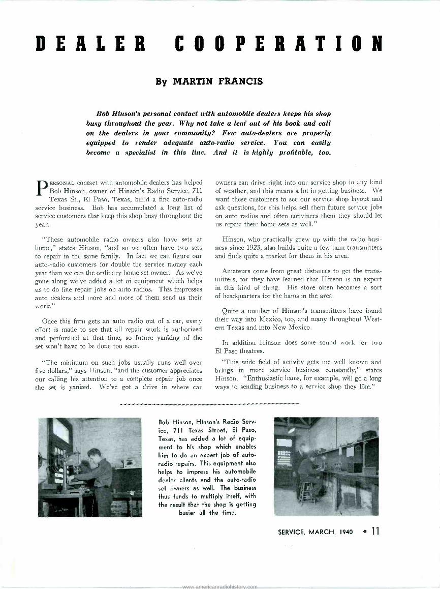
Bob Hinson's personal contact with automobile dealers keeps his shop busy throughout the year. Why not take a leaf out of his book and call on the dealers in your community? Few auto -dealers are properly equipped to render adequate auto -radio service. You can easily become a specialist in this line. And it is highly profitable, too.
PERSONAL contact with automobile dealers has helped Bob Hinson, owner of Hinson's Radio Service, 711 Texas St., El Paso, Texas, build a fine auto -radio
service business. Bob has accumulated a long list of service customers that keep this shop busy throughout the year.
"These automobile radio owners also have sets at home," states Hinson, "and so we often have two sets to repair in the same family. In fact we can figure our auto -radio customers for double the service money each year than we can the ordinary home set owner. As we've gone along we've added a lot of equipment which helps us to do fine repair jobs on auto radios. This impresses auto dealers and more and more of them send us their work."
Once this firm gets an auto radio out of a car, every effort is made to see that all repair work is authorized and performed at that time, so future yanking of the set won't have to be done too soon.
"The minimum on such jobs usually runs well over five dollars," says Hinson, "and the customer appreciates our calling his attention to a complete repair job once the set is yanked. We've got a drive in where car
owners can drive right into our service shop in any kind of weather, and this means a lot in getting business. We want these customers to see our service shop layout and ask questions, for this helps sell them future service jobs on auto radios and often convinces them they should let us repair their home sets as well."
Hinson, who practically grew up with the radio busi- ness since 1923, also builds quite a few ham transmitters and finds quite a market for them in his area.
Amateurs come from great distances to get the trans- mitters, for they have learned that Hinson is an expert in this kind of thing. His store often becomes a sort of headquarters for the hams in the area.
Quite a number of Hinson's transmitters have found their way into Mexico, too, and many throughout West- ern Texas and into New Mexico.
In addition Hinson does some sound work for two El Paso theatres.
"This wide field of activity gets me well known and brings in more service business constantly," states Hinson. "Enthusiastic hams, for example, will go a long ways to sending business to a service shop they like."
Bob Hinson, Hinson's Radio Serv-
ice, 711 Texas Street, El Paso,
Texas, has added a lot of equip- ment to his shop which enables
him to do an expert job of auto-
radio repairs. This equipment also
helps to impress his automobile dealer clients and +he auto -radio set owners as well. The business
thus tends to multiply itself, with
the result that the shop is getting busier all the time.
SERVICE, MARCH, 1940 1
www.americanradiohistory.com

CUSTOMER PSYCHOLOGY
By WALTER KENWORTH
Photo courtesy Clough-Brenglc
Customer psychology plays an important ,",",,"o "' role for James F. Waldron, proprietor of Community Radio Laboratory, Norwood, Mass. The instruments shown are, from left to right, CRA oscillograph; Model 110 signal generator, Model III Uni- signal frequency modulator and Model 135 Uni -checker on rack and a Model
79C beat -frequency oscillator.
FFFORTS to educate the Service Man in service technique are very desirable and are, of course,
necessary. However, on the psycho- logical side, there is and always will be an unsatisfied need for further in- formation. You may be at the top of your profession in technical knowledge yet you can use guidance in broadening your contacts and harmonizing your re- lations with others.
Consider a few common problems and how we can meet them. Suppose, for example, that a receiver is returned late; the owner has missed a valued program and she is thoroughly peeved. (Of course, it is understood that as a general practice the set should be re- turned on time, but that in this case an emergency developed such as un- forseen trouble in the set.) The cus- tomer must be handled with tact, you must keep cool and try to plan your policy, especially when the customer follows an unexpected line.
One way of handling this would be to say, immediately upon entering, "I am sorry to be late, madam. Later when the air has cleared the matter can be explained. "When it came time to return your set, I was not com- pletely satisfied because I try to do work only of the highest quality. I went over it completely and made it perfect. I felt convinced that when you understood the reason for the delay, you would approve it. Then you will not only have proved that "a soft answer turneth away wrath but have turned an irate customer into an ad- miring one. Strive to leave behind a pleased owner, satisfied with your work. From such a customer may come much future business.
Suppose, again, that a set owner is criticising another Service Man in your presence. Several ways of combatting this are possible.
You can change the subject; excuse
12 SERVICE, MARCH, 1940
SERVICE INSTRUCTOR, RCA INSTITUTES
IT is the purpose of this article to discuss some of the psychologi- cal problems which the Service Man
meets. We should be able to draw out of it something which will aid us
in each new situation of the same sort which arises. It may be said that this is not possible because each case in human relations is different from the other. This latter certainly is true, yet it is certain too that in all such situa- tions something common does appear and it is this we can use.
,,,.,,,1,1,,,,,111111,111111111 ,111111111,,,,,,1,,,,,,111111111,1111,1,1111111111,1,1,11,111,,,,,11111,11
him because of the difficult job he had to do; you can say nothing or you can refer to his good points. Most Service Men have heard the customer say, "I don't think much of A's work on my set. It's worse than when he took it and his charges are too high. Serv- ice Man B can say to this, "I certainly like your receiver, madame. It was once one of the best and even now has especially clear tone (if it is true, of course). Or, he may say, "Your re- ceiver was once one of the most compli- cated on the market and even now re- quires skill and patience to repair it properly. Or as mentioned before, he may become particularly busy at that moment and say nothing. But you can say, and this is recommended as the best, "I'm surprised at that, Madame, because A is considered to be very square in making things right."
When we say, it isn't ethical to criti- cize a fellow Service Man, we mean that we wouldn't want him to join in criticism of us if he were in our place in this spot. Something good can be found in the poorest Service Man and here is the time to bring it forth.
As an other example, suppose that you are about to take a set from a home to your bench for repair and that the owner is doubtful about letting you take it. Here is a time for you to express confidence in your ability, not, how- ever, with hesitation or with exaggera- tion. If your attitude is one of sincere confidence, the owner will feel that you know what is to be done and how to do it and thus will have faith in you. Since the owner knows nothing of what is going into the set to make it work,
he must depend entirely upon his trust in you.
An owner may demand further work to be done without payment shortly after the original job has been finished. You may not be responsible in any way for the added work necessary and de- manded. This calls for diplomacy. If the customer is a profitable one, the cost of the added work should be weighed against future business from the customer. If the cost is to be rather high and further business from that source is doubtful, it may be desirable to insist either on full payment or on a compromise for partial payment. If the work demanded is due in part to your negligence then the square thing is to do it even at a loss.
If a customer delays payment beyond all reason, all the judgment you have may need to be used. The method one Service Man used should be used with caution. After he had repaired the re- ceiver, and was holding it in an effort to collect payment, he received a short note from the owner stating, "Check is ready, send set." The Service Man re- plied with another, equally short note stating "Set is ready, send check."
As a general practice, it is wiser to apply pressure gently over a longer time than to try to collect immediately under too high a pressure.
The foregoing situations have been discussed in detail. Others are:
(a) When the old set must be re- placed.
(b) The tact needed when you are plied with questions before you have found the trouble.
(c) What to do when the customer insists on knowing exactly when his receiver will be returned and what it will cost, especially when it is a "fad- ing" job.
(d) Handling the type of customer who phones Service Man after Service Man, for a price on his job.
(e) When the customer demands re- placement and the guarantee period has just passed.
These are problems in human rela- tions, and for instruction in them, free discussion is one of the best methods. This can properly be held, and in some cases is being held, in the association and club meetings of Service Men.
www.americanradiohistory.com
5REASONS WHY THE DEMAND FOR UTAH VIBRATORS INCREASED 63% The preference for Utah Vibrators has grown with the industry, because most of she
important vibrator developments have originated in the Utah laboratory. Outstanding design and advanced engineering have maintained their In 1939 she
demand for Utah Vibrators increased 63% brause:
The preference Vibrators has grown because of the have in Outstanding
design and advanced engineering have maintained leadership. In 1939 the demand Vibrators increased 63% because:
1 Complete exact replacements can be made with the Utah line.
2 Absolute dependability is assured by Utah's rugged, time -proved construction.
3 Finest materials obtainable are used in the manufacture of Utah Vibrators.
4 "Life Tested" in Utah's laboratory-the industry's most versatile and best equipped.
5 12 months guarantee-against defective workmanship and materials.
The assurance of complete satisfaction has led thousands of users to standardize on Utah Vibrators. You, too, can be sure of all these advantages by insisting on Vibrators that carry the Utah label. For Vibrator information, write Utah Radio Products Co., 816 Orleans Street, Chicago, Illinois. Canadian Sales Office: 414 Bay Street, Toronto, Ont., Canada. Cable Address: Utaradio, Chicago.
IOW
VIBRATORS SPEAKERS TRANSFORMERS UTAH -CARTER PARTS
diä
SERVICE, MARCH, 1940 13
www.americanradiohistory.com
AMPLIFIER RATINGS AN AMPLIFIER is but one part in a
complete transmission or repro- duction system. We are inter-
ested in the performance of the whole system; that is, how well the original sound is reproduced and with how much gain in power. Measurements should then really be made over the whole system from microphone to speaker. Such acoustic measurements are very hard to make and so we have separate ratings for each link in the chain.
It has become customary to let each part stand by itself and give as faithful reproduction as possible rather than to have one part cancel the shortcomings of another part. Such an arrangement makes it easier to use different types of microphones and pickups with the same amplifier.
Ratings which will prove practically useful should satisfy two conditions: 1) The ratings and measurement procedure should be so standardized that they can be repeated by anyone skilled in the art, yielding the same result. 2) The meas- urements should be made in such a way that the unit under test works under practically the same conditions as it will encounter in actual operation. This means that it works out of the same im- pedance and into the same impedance as in practical use.
This second condition is hard to satis- fy since there are now so many different types of microphones, pickups and speakers. The next best thing is to agree on some standard system of rating and a standard measurement procedure so that products of different manufac- turers may be compared fairly.
Introduction of standardization has been slow. RMA has now set some standards for this field but as yet the standardization has not gone far enough. The following is a discussion of the rat- ings now in use and their interpreta- tion.
output ratings
Power output is measured in watts but sometimes it may be given in deci- bels. In the latter case there should be an accepted zero level. For public ad- dress work this zero level is defined as
By JOHN M. BORST
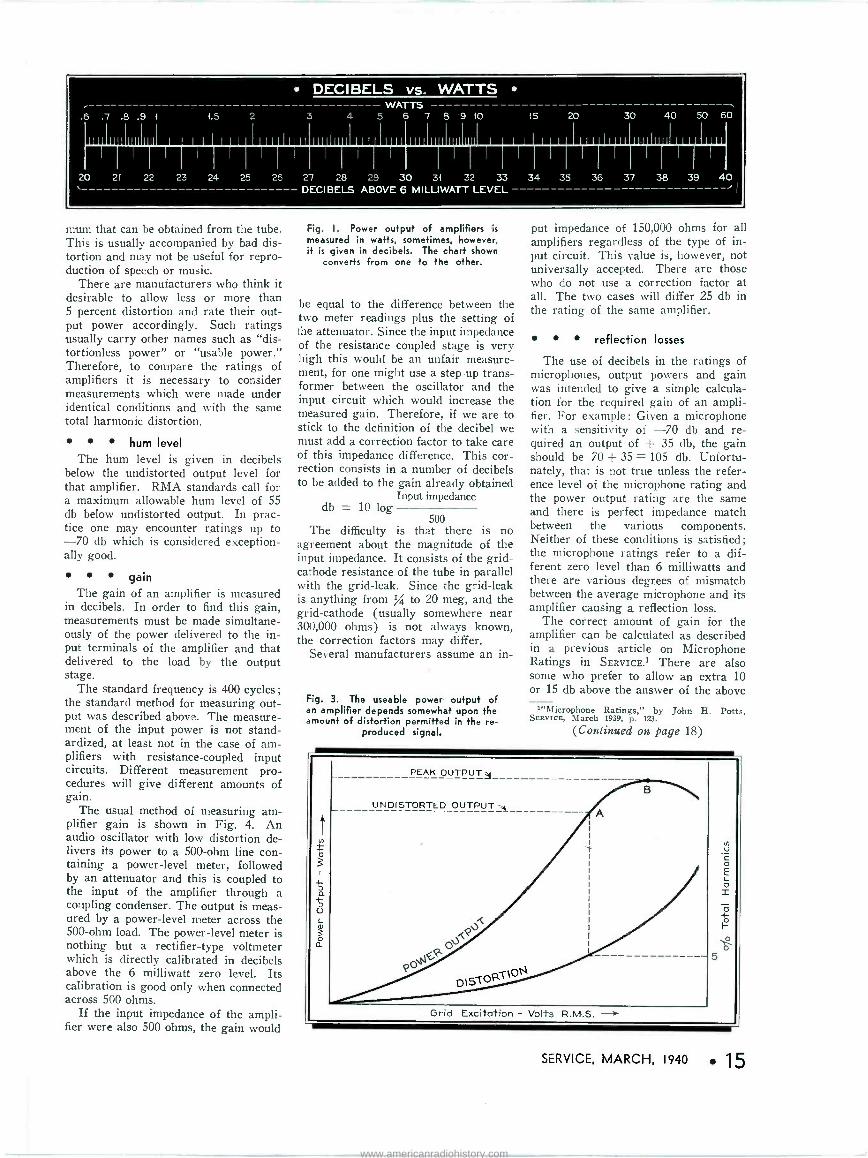
6 milliwatts, or, more accurately as n milliamperes through 600 ohms. Fig. 1 is a chart for the conversion of power levels in decibels to watts or vice versa.
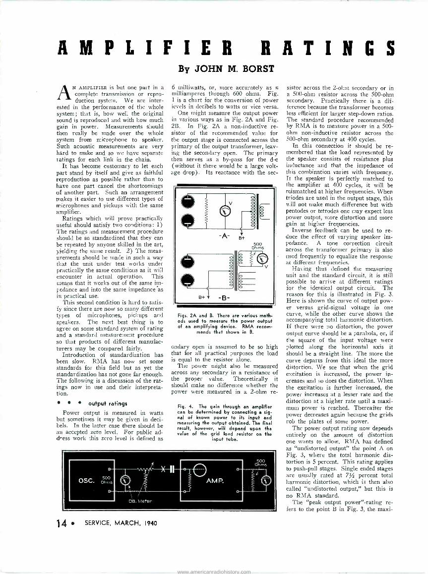
One might measure the output power in various ways as in Fig. 2A and Fig. 2B. In Fig. 2A a non -inductive re- sistor of the recommended value for the output stage is connected across the primary of the output transformer, leav- ing the secondary open. The primary then serves as a by-pass for the d -c (without it there would be a large volt- age drop). Its reactance with the sec -
Ill -A- B+
5+ -B-
500 Ohms
Figs. 2A and B. There are various meth- ods used to measure the power output of an amplifying device. RMA recom-
mends that shown in B.
ondary open is assumed to be so high that for all practical purposes the load is equal to the resistor alone.
The power might also be measured across any secondary in a resistance of the proper value. Theoretically it should make no difference whether the power were measured in a 2 -ohm re -
Fig. 4. The gain through an amplifier can be determined by connecting a sig- nal of known power to its input and measuring the output obtained. The final result, however, will depend upon the value of the grid load resistor on the
input tube.
OSC.
o
500 Ohms
o-
1
DB. Meter
e AMP.
o
500 Ohm
14 SERVICE, MARCH, 1940
sistor across the 2 -ohm secondary or in a 500 -ohm resistor across the 500 -ohm secondary. Practically there is a dif- ference because the transformer becomes less efficient for larger step-down ratios. The standard procedure recommended by RMA is to measure power in a 500 - ohm non -inductive resistor across the 500 -ohm secondary at 400 cycles.
In this connection it should be re- membered that the load represented by the speaker consists of resistance plus inductance and that the impedance of this combination varies with frequency. Ii the speaker is perfectly matched to the amplifier at 400 cycles, it will be mismatched at higher frequencies. When triodes are used in the output stage, this will not make much difference but with pentodes or tetrodes one may expect less power output, more distortion and more gain at higher frequencies.
Inverse feedback can be used to re- duce the effect of varying speaker im- pedance. A tone correction circuit across the transformer primary is also used frequently to equalize the response at different frequencies.
Having thus defined the measuring unit and the standard circuit, it is still possible to arrive at different ratings for the identical output circuit. The reason for this is illustrated in Fig. 3. Here is shown the curve of output pow- er versus grid -signal voltage in one curve, while the other curve shows the accompanying total harmonic distortion. If there were no distortion, the power output curve should be a parabola, or, if the square of the input voltage were plotted along the horizontal axis it should be a straight line. The more the curve departs from this ideal the more distortion. We see that when the grid excitation is increased, the power in- creases and so does the distortion. When the excitation is further increased, the power increases at a lesser rate and the distortion at a higher rate until a maxi- mum power is reached. Thereafter the power decreases again because the grids rob the plates of some power.
The power output rating now depends entirely on the amount of distortion one wants to allow. RMA has defined as "undistorted output" the point A on Fig. 3, where the total harmonic dis- tortion is 5 percent. This rating applies to push-pull stages. Single ended stages are usually rated at 7% percent total harmonic distortion, which is then also called "undistorted output," but this is no RMA standard.
The "peak output power" -rating re- fers to the point B in Fig. 3, the maxi-
www.americanradiohistory.com
DECIBELS vs. WATTS WATTS
.6 .7 .8 .9 1 1.5 2 3 4 5 6 7 8 9 10
III IIJIIIII III 1 1 1 1 1 1 1 II III1II 11 111III III IIJIIIII III 1
20 21 22 23 24 25 26
DECIBELS ABOVE 6 MILLIWATT LEVEL
15 20 30 40 50 60
111 I1 Hi lu J 1111
27 28 29 30 31 32 33 34 35 36 37 38 39 40
mum that can be obtained from the tube. This is usually accompanied by bad dis- tortion and may not be useful for repro- duction of speech or music.
There are manufacturers who think it desirable to allow less or more than 5 percent distortion and rate their out- put power accordingly. Such ratings usually carry other names such as "dis- tortionless power" or "usable power." Therefore, to compare the ratings of amplifiers it is necessary to consider measurements which were made under identical conditions and with the same total harmonic distortion.
hum level The hum level is given in decibels
below the undistorted output level for that amplifier. RMA standards call for a maximum allowable hum level of 55 db below undistorted output. In prac- tice one may encounter ratings up to -70 db which is considered exception- ally good.
gain The gain of an amplifier is measured
in decibels. In order to find this gain, measurements must be made simultane- ously of the power delivered to the in- put terminals of the amplifier and that delivered to the load by the output stage.
The standard frequency is 400 cycles; the standard method for measuring out- put was described above. The measure- ment of the input power is not stand- ardized, at least not in the case of am- plifiers with resistance -coupled input circuits. Different measurement pro- cedures will give different amounts of gain.
The usual method of measuring am- plifier gain is shown in Fig. 4. An audio oscillator with low distortion de- livers its power to a 500 -ohm line con- taining a power -level meter, followed by an attenuator and this is coupled to the input of the amplifier through a coupling condenser. The output is meas- ured by a power -level meter across the 500 -ohm load. The power -level meter is nothing but a rectifier -type voltmeter which is directly calibrated in decibels above the 6 milliwatt zero level. Its calibration is good only when connected across 500 ohms.
If the input impedance of the ampli- fier were also 500 ohms, the gain would
Fig. I. Power output of amplifiers is
measured in watts, sometimes, however, it is given in decibels. The chart shown
converts from one to the other.
be equal to the difference between the two meter readings plus the setting of the attenuator. Since the input impedance of the resistance coupled stage is very high this would be an unfair measure- ment, for one might use a step-up trans- former between the oscillator and the input circuit which would increase the measured gain. Therefore, if we are to stick to the definition of the decibel we must add a correction factor to take care of this impedance difference. This cor- rection consists in a number of decibels to be added to the gain already obtained
Input impedance db = 10 log
500 The difficulty is that there is no
agreement about the magnitude of the input impedance. It consists of the grid - cathode resistance of the tube in parallel with the grid -leak. Since the grid -leak is anything from % to 20 meg, and the grid -cathode (usually somewhere near 300,000 ohms) is not always known, the correction factors may differ.
Several manufacturers assume an in -
Fig. 3. The useable power output of an amplifier depends somewhat upon the amount of distortion permitted in the re-
produced signal.
put impedance of 150,000 ohms for all amplifiers regardless of the type of in- put circuit. This value is, however, not universally accepted. There are those who do not use a correction factor at all. The two cases will differ 25 db in the rating of the same amplifier.
reflection losses
The use of decibels in the ratings of microphones, output powers and gain was intended to give a simple calcula- tion for the required gain of an ampli- fier. For example: Given a microphone with a sensitivity of -70 db and re- quired an output of + 35 db, the gain should be 70 + 35 = 105 db. Unfortu- nately, that is not true unless the refer- ence level of the microphone rating and the power output rating are the same and there is perfect impedance match between the various components. Neither of these conditions is satisfied; the microphone ratings refer to a dif- ferent zero level than 6 milliwatts and there are various degrees of mismatch between the average microphone and its amplifier causing a reflection loss.
The correct amount of gain for the amplifier can be calculated as described in a previous article on Microphone Ratings in SERVICE.1 There are also some who prefer to allow an extra 10 or 15 db above the answer of the above
1"Microphone Ratings," by John H. Potts, SERVICE, March 1939. p. 123.
(Continued on page 18)
SERVICE, MARCH, 1940 15
www.americanradiohistory.com
E I '-
33Mw 47 MM
C3 1I c
le
L2 C2
475IL-
105 V.
6SA7GT, L3
a
105V. - 1.05
c T r 2
32.411.
105v.
6SK7GT L4
105V.r
c qq 9 0¡
60V.on 550V. scale 130v.
607GT 40 v. on 500V. Scale 6J5G4 39Mw .005 25L6GT '
bc I
Iol9
1
32.4 11 CI41r----._470
MMF.
410M= w =
FIG.1
L Ir 0 0
55 .C.
65A
Sr
r--lc5
ALZO BALLAST
e i54oAC
500 A.C. i 0 S
SECSIOB AMT
SECTION
/,IR2 2.2MEG. 5 MEG. VOL- CONT.
220u)--21.. ROO C
Fvvw
i
.1 C25
o ó3 Cu
R20
C26
000'175
R3
C13 .03
C6 .005
RS
fi CIS T 220 1.G MMF MEG
3
R4
R6
2V.
e 27 3300 co
RB
R9
470 Mw
'Cr
ce . RIO 105 150w V
TI L5
11s,D1 v SPAR
30MFD.,150V
45MEG. 400 M w,
ó4,53
.5
-C2B
C17
C9 25Z6GT
R
IM } w /
CIO
SO M FD., 150 V.
607 65A7 25L6 GT GT ST
615 GT
MI
T2 CONVERTER 3 UNIT
R2I
ALL VOLTAGES MEASUR- ED FROM B-
1000 w per V. Meter
6567 2526 GT GT
z T CII .05
on R3
135
PI
RI 4
-4
CONNECTIONS SHOWN
DOTTED APPLY ONLY TO
A.C.MODELS WHICH DO
NOT HAVE CONVERTER UNIT
L6 4Nh 027 t IIOV.D.C. 0 `\\\\\1 CHASSIS
52
SI
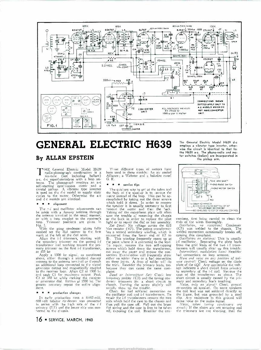
GENERAL ELECTRIC H639 By ALLAN EPSTEIN
THE General Electric Model H639 radio -phonograph combination is a six -tube (not including ballast)
a -c, d -c superheterodyne with a loop an- tenna. The phonograph employs an a -c self-starting synchronous motor and a crystal pickup. A vibrator type inverter is used on the d -c model to supply sixty cycles to the motor. Otherwise the a -c and d -c models are identical.
alignment
The r -f and oscillator adjustments can be made with a dummy antenna through the antenna terminal in the usual manner, or with a loop coupled to the receiver's loop. Trimmer positions are given in Fig. 1.
With the gang condenser plates fully meshed set the dial pointer to the first mark at the left of the dial scale.
Align the i -f trimmers, starting with the secondary trimmer on the second i -f transformer and working toward the pri- mary trimmer on the first i -f transformer, at 455 kc
Apply a 1500 kc signal, as mentioned above, either through a standard dummy antenna to the antenna terminal or through an additional loop connected to the signal generator output and magnetically coupled to the receiver loop. Align C2 at 1500 kc and peak Cl for maximum output. Peak C3 at 580 kc while rocking the receiver or generator dial. Retrim at 1500 kc. For greater accuracy repeat the entire align- ment.
production changes
In early production runs a 0.002-mfd, 600 -volt tubular condenser was connected in series with the high side of the r -f primary (L1) and the lower side was con- nected to the chassis.
16 SERVICE, MARCH, 1940
Three different types of motors have been used in these models : An air cooled Alliance ; a Webster and a bakelite cased G. E.
service tips
The quickest way to get at the tubes and the back of the speaker is to remove the motor instead of the loop. This can be ac- complished by taking out the three screws which hold it dbtvn. In order to remove the speaker it is usually necessary to first remove the motor and then the back. Taking off the escutcheon plate will often save the trouble of removing the chassis or the back in order to replace the pilot light or to repair the dial or key assembly.
Set Dead: No voltage across the 6J5 bias resistor (R7). The output transformer has a second secondary winding, which is connected from the lower end of R7 to B-. This winding frequently opens up at the point where it is connected to the lead. To repair, remove the two self -tapping screws which hold down the transformer, cut away the paper and expose the con- nection. Examination will frequently show either no solder there or a bad connection on these joints. A drop of solder will do the trick. Resolder the primary leads, too, because they can cause the same com- plaint.
Dead or Intermittent Set: Check low frequency padder (C3) and the tuning con- denser trimmers for a short circuit to chassis. Turning the screw slightly will usually show up the trouble.
Check for bad soldered connection on the oscillator coil and i -f transformers. To repair the i -f transformers remove the two nuts which hold the case to the chassis and then pull the case off. Pull out the brass flat spring and the case is free to be taken off, exposing the coil. Resolder the con -
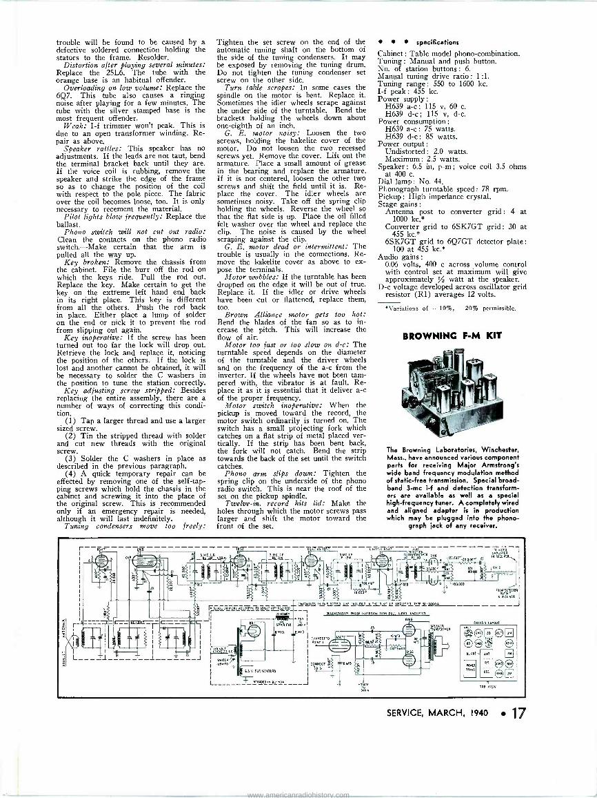
The General Electric Model H639 d -c employs a vibrator type inverter, other- wise the circuit is identical to that for the H639 a -c. The phono -radio and mo- tor switches (below) are incorporated in
the pickup arm.
TONE ARM SHAFT
PHONO -RADIO SWITCH
PHONO- MOTOR SWITCH
RED
GREEN TO MINUS B
BLACK (SHIELDED) TO BOTTOM OF DET. TRANSFORMER SECONDARY
RED (SHIELDED) TO TOP OF VOLUME CONTROL
nections, first being careful to clean the ends of the wires thoroughly.
Oscillation, no reception: Condenser (C5) was welded to the chassis. The welded connection occasionally breaks off, causing this complaint.
Oscillation on stations: This is usually i -f oscillation. Separating the plate leads from the grid leads of the two i -f trans- formers will usually clear up this trouble.
Intermittent, modulation hum: Resolder bad connections on loop antenna.
Hum and noise on any position of vol- ume control: Check voltage on the diode plate of the 6Q7. Any appreciable d -c volt- age indicates a short circuit from primary to secondary of the i -f coil. Remove the case of the transformer as above. The short circuit is usually caused by the pri- mary and secondary leads touching.
Noise, only on signal: Check ground connection on speaker. On some speakers the coil lead was not soldered directly to the frame, but was grounded by a steel clip. Any resistance in this ground will cause noise on the audio signal.
Noise, when tuning condensers are struck: If the plates are not scraping and the trimmers are not shorting, then the
www.americanradiohistory.com
trouble will be found to be caused by a defective soldered connection holding the stators to the frame. Resolder.
Distortion after playing several minutes: Replace the 25L6. The tube with the orange base is an habitual offender.
Overloading on low volume: Replace the 6Q7. This tube also causes a ringing noise after playing for a few minutes. The tube with the silver stamped base is the most frequent offender.
Weak: I -f trimmer won't peak. This is due to an open transformer winding. Re- pair as above.
Speaker rattles: This speaker has no adjustments. If the leads are not taut, bend the terminal bracket back until they are. If the voice coil is rubbing, remove the speaker and strike the edge of the frame so as to change the position of the coil with respect to the pole piece. The fabric over the coil becomes loose, too. It is only necessary to recement the material.
Pilot lights blow frequently: Replace the ballast.
Phono switch will not cut out radio: Clean the contacts on the phono radio switch.-Make certain that the arm is pulled all the way up.
Key broken: Remove the chassis from the cabinet. File the burr off the rod on which the keys ride. Pull the rod out. Replace the key. Make certain to get the key on the extreme left hand end back in its right place. This key is different from all the others. Push the rod back in place. Either place a lump of solder on the end or nick it to prevent the rod from slipping out again.
Key inoperative: If the screw has been turned out too far the lock will drop out. Retrieve the lock and replace it, noticing the position of the others. If the lock is lost and another cannot be obtained, it will be necessary to solder the C washers in the position to tune the station correctly.
Key adjusting screw stripped: Besides replacing the entire assembly, there are a number of ways of correcting this condi- tion.
(1) Tap a larger thread and use a larger sized screw.
(2) Tin the stripped thread with solder and cut new threads with the original screw.
(3) Solder the C washers in place as described in the previous paragraph.
(4) A quick temporary repair can be effected by removing one of the self -tap- ping screws which hold the chassis in the cabinet and screwing it into the place of the original screw. This is recommended only if an emergency repair is needed, although it will last indefinitely.
Tuning condensers move too freely:
Tighten the set screw on the end of the automatic tuning shaft on the bottom of the side of the tuning condensers. It may be exposed by removing the tuning drum. Do not tighten the tuning condenser set screw on the other side.
Turn table scrapes: In some cases the spindle on the motor is bent. Replace it. Sometimes the idler wheels scrape against the under side of the turntable. Bend the brackets holding the wheels down about one -eighth of an inch.
G. E. motor noisy: Loosen the two screws, holding the bakelite cover of the motor. Do not loosen the two recessed screws yet. Remove the cover. Lift out the armature. Place a small amount of grease in the bearing and replace the armature. If it is not centered, loosen the other two screws and shift the field until it is. Re- place the cover. The idler wheels are sometimes noisy. Take off the spring clip holding the wheels. Reverse the wheel so that the flat side is up. Place the oil filled felt washer over the wheel and replace the clip. The noise is caused by the wheel scraping against the clip.
G. E. motor dead or intermittent: The trouble is usually in the connections. Re- move the Bakelite cover as above to ex- pose the terminals.
Motor wobbles: If the turntable has been dropped on the edge it will be out of true. Replace it. If the idler or drive wheels have been cut or flattened, replace them, too.
Brown Alliance motor gets too hot: Bend the blades of the fan so as to in- crease the pitch. This will increase the flow of air.
Motor too fast or too slow on d -c: The turntable speed depends on the diameter of the turntable and the driver wheels and on the frequency of the a -c from the inverter. If the wheels have not been tam- pered with, the vibrator is at fault. Re- place it as it is essential that it deliver a -c of the proper frequency.
Motor switch inoperative: When the pickup is moved toward the record, the motor switch ordinarily is turned on. The switch has a small projecting fork which catches on a flat strip of metal placed ver- tically. If the strip has been bent back, the fork will not catch. Bend the strip towards the back of the set until the switch catches.
Phono arm slips down: Tighten the spring clip on the underside of the phono radio switch. This is near the roof of the set on the pickup spindle.
Twelve -in. record hits lid: Make the holes through which the motor screws pass larger and shift the motor toward the front of the set.
specifications
Cabinet : Table model phono -combination. Tuning : Manual and push button. No. of station buttons : 6. Manual tuning drive ratio : 1:1. Tuning range: 550 to 1600 kc. I -f peak : 455 kc. Power supply :
H639 a -c : 115 v, 60 c. H639 d -c ; 115 v, d -c.
Power consumption :
H639 a -c : 75 watts. H639 d -c : 85 watts.
Power output : Undistorted : 2.0 watts. Maximum : 2.5 watts
Speaker : 6.5 in, p -m ; voice coil 3.5 ohms at 400 c.
Dial lamp : No. 44. Phonograph turntable speed: 78 rpm. Pickup : High impedance crystal. Stage gains:
Antenna post to converter grid: 4 at 1000 kc.*
Converter grid to 6SK7GT grid : 30 at 455 kc.*
6SK7GT grid to 6Q7GT detector plate :
100 at 455 kc.* Audio gains :
0.06 volts, 400 c across volume control with control set at maximum will give approximately / watt at the speaker.
D -c voltage developed across oscillator grid resistor (Rl) averages 12 volts.
*Variations of -10%, -20% permissible.
BROWNING F -M KIT
The Browning Laboratories, Winchester, Mass., have announced various component parts for receiving Major Armstrong's wide band frequency modulation method of static -free transmission. Special! broad- band 3 -mc i -f and detection transform- ers are available as well as a special high -frequency tuner. A completely wired and aligned adapter is in production which may be plugged into the phono-
graph jack of any receiver.
a 3.MC I f -11143b1.
33-
.01 b r 3.MCIi
-- - -100.MM1
10,00 N CONPoNENTS IN iwlS DOT?EQ Ile INCLUDED INC 3.MC 1 AMPLIFIER TYPE DL-3i000A
$ ISxD..at nOPt ACCgID. c 10 5[MDITIÑTY 11E.1iGED r DEDENtRAIIVE eNASE INvERSION PUSN PULL 1011I0 AMPLIiIER
GVOO JI N
+i50 i
DO sewn rus .DProD M I
=.MFD. =.MfD
fmtt ió ttttr
L
Pens,T OS.IrO
CONNECT TO
Il POINT
i
- CONNECT M
0.3 V. faR NEATERS TO 6
_1_ IN¢1[OE11IN RL -,3A
.T30V
3mv.
.D5
100,000',
*Wes
--- Te COV0 AMPLIFIER
00" .05 IN RECEIVER,.
FROM DElECTOR WtPUi
IN PLUMS
_J
CNASSIS UNCUT
'et CNC 3D SJT
eD çó nNl
EL00T
POWER
TRANS i SN
8E OP VIEW
SERVICE, MARCH, 1940 17
www.americanradiohistory.com
YOUR NAME AND
ADDRESS IMPRINTED ON ALL FORMS
1 -Save time and money and get more business through Syl- vania's latest service helps. You will want the Three -in -One Service Form that combines our invoice, guarantee, job rec- ord card and a promotional follow-up card for mailing. 2 -Many servicemen and deal- ers use Sylvania's Job Record Card and find it's the handiest way to keep things straight. This new form combines your job record, a record for the customer and a guarantee. 3-Sylvania's "Guarantee Package" is a business getter. It provides you with a "selling guarantee" and repair recom- mendation form all in one. There's a customer guarantee form and a large one for your shop. You can order as few as 100 of any of these Sylvania helps all imprinted with your name-at bargain prices. Send the coupon-today-for samples of these money savers.
Hygrade Sylvania Corporation S 3 Emporium, Pa.
Please rush free samples and prices on your
3 -in -1 Form Job Record Card "Guarantee Package"
Name
Address City
---------St=te- 8 SERVICE, MARCH, 1940
AMPLIFIER RATINGS
(Continued from page 15)
example to take care of these losses.
frequency characteristic
The measurement of the frequency characteristic is done with the same ap- paratus as the measurement of gain, but there is one important difference. The input capacity of the tube is across the the grid leak and the generator. This input capacity amounts to the grid - cathode capacity plus the grid -plate ca- pacity multiplied by the gain in the first stage. In the case of pentodes it is not very important, but with high -mu tri- odes, such as the 75 or 6F5, it may amount to 150 mmfd.
It will make considerable difference in high -frequency response whether this 150 mmfd is across a 15-meg grid leak and a high -impedance microphone or whether it is across a 500 -ohm line. Therefore we must simulate the average condition by inserting a resistance at the point X in Fig. 4. There is again no agreement on the size of this re- sistor. Some manufacturers use the 10,000 -ohm output terminals of their signal generator. Others insert a resist- ance anywhere between 5,000 and 20,000 ohms. The frequency characteristic will look flatter with the lower values of resistance.
When the amplifier is then connected to a microphone or pickup a consider- able change can be expected because of the magnitude and phase angle of the microphone impedance. The crystal microphone has an impedance equivalent to a condenser and resistor in series. The tube capacity results in a loss of sensitivity but does not alter the fre- quency response. The input resistance of the amplifier, however, affects the low notes, the lower the resistance the less low -frequency response. A velocity microphone or a dynamic microphone is equivalent in impedance to an induct- ance and a resistance. The input resist- ance of the amplifier then affects the gain slightly, but the input capacity re- duces high -frequency response.
There are still other factors which will affect the frequency characteristic. For instance, it makes a difference whether the measurements were made with a weak signal or with a strong signal.
distortion There are three kinds of distortion :
(1) Amplitude distortion or harmonic distortion; (2) Frequency distortion; (3) Phase distortion. Generally, if one of these three types of distortion is pres- ent, all three are present.
Harmonic distortion is perhaps the most annoying of the three. It consists
Plan now to go to the
Radio Parts National
Trade Show
gu44 11 /4 14 It's the right clue, if you follow through. Because that's where you'll find many a good idea which you can turn into profit. Yes, even one thought, one idea would well repay you. That's why the Trade Show is so vital to your business and to you. That's why you can't afford to miss it. Plan now-to go!
JOBBER DAYS Tues., Wed., Thurs., June 11,12,13
OPEN HOUSE Friday, June 14
STEVENS HOTEL, CHICAGO
Radio Parts National Trade Show
Lxecuii e l ice 53 West Jackson Boulevard Chicago
www.americanradiohistory.com
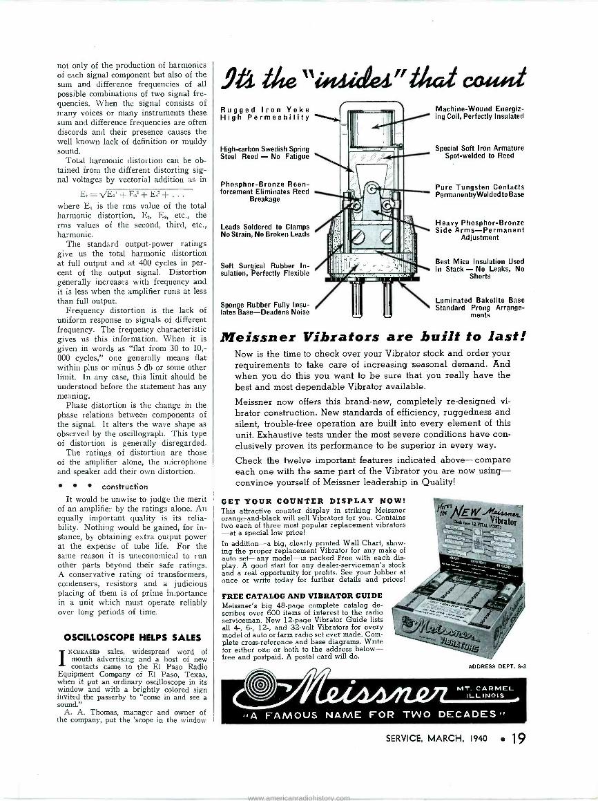
not only of the production of harmonics of each signal component but also of the sum and difference frequencies of all possible combinations of two signal fre- quencies. When the signal consists of many voices or many instruments these sum and difference frequencies are often discords and their presence causes the well known lack of definition or muddy sound.
Total harmonic distortion can be ob- tained from the different distorting sig- nal voltages by vectorial addition as in
Et_\/E2'+E8'+E.Q ... where E, is the rms value of the total harmonic distortion, E,, E,, etc., the rms values of the second, third, etc., harmonic.
The standard output -power ratings give us the total harmonic distortion at full output and at 400 cycles in per- cent of the output signal. Distortion generally increases with frequency and it is less when the amplifier runs at less than full output.
Frequency distortion is the lack of uniform response to signals of different frequency. The frequency characteristic gives us this information. When it is given in words as "flat from 30 to 10,- 000 cycles," one generally means flat within plus or minus 5 db or some other limit. In any case, this limit should be understood before the statement has any meaning.
Phase distortion is the change in the phase relations between components of the signal. It alters the wave shape as observed by the oscillograph. This type of distortion is generally disregarded.
The ratings of distortion are those of the amplifier alone, the microphone and speaker add their own distortion.
construction
It would be unwise to judge the merit of an amplifier by the ratings alone. An equally important quality is its relia- bility. Nothing would be gained, for in- stance, by obtaining extra output power at the expense of tube life. For the same reason it is uneconomical to run other parts beyond their safe ratings. A conservative rating of transformers, condensers, resistors and a judicious placing of them is of prime importance in a unit which must operate reliably over long periods of time.
OSCILLOSCOPE HELPS SALES
INCREASED sales, widespread word of mouth advertising and a host of new contacts came to the El Paso Radio
Equipment Company of El Paso, Texas, when it put an ordinary oscilloscope in its window and with a brightly colored sign invited the passerby to "come in and see a sound."
A. A. Thomas, manager and owner of the company, put the 'scope in the window
9A ilte"ifraideA." Mal cafflet Rugged Iron Yoke High Permeability
High -carbon Swedish Spring Steel Reed - No Fatigue
Phosphor -Bronze Reen- forcement Eliminates Reed
Breakage
Leads Soldered to Clamps No Strain, No Broken Leads
Soft Surgical Rubber In- sulation, Perfectly Flexible
Sponge Rubber Fully Insu- lates Base-Deadens Noise
Machine -Wound Energiz- ing Coil, Perfectly Insulated
Special Soft Iron Armature Spot-welded to Reed
Pure Tungsten Contacts PermanentlyWelded to Base
Heavy Phosphor -Bronze Side Arms-Permanent
Adjustment
Best Mica Insulation Used in Stack - No Leaks, No
Shorts
Laminated Bakelite Base Standard Prong Arrange-
ments
Meissner Vibrators are built to last! Now is the time to check over your Vibrator stock and order your requirements to take care of increasing seasonal demand. And when you do this you want to be sure that you really have the best and most dependable Vibrator available.
Meissner now offers this brand-new, completely re -designed vi-
brator construction. New standards of efficiency, ruggedness and silent, trouble -free operation are built into every element of this unit. Exhaustive tests under the most severe conditions have con- clusively proven its performance to be superior in every way.
Check the twelve important features indicated above compare each one with the same part of the Vibrator you are now using- convince yourself of Meissner leadership in Quality!
GET YOUR COUNTER DISPLAY NOW! This attractive counter display in striking Meissner orange -and -black will sell Vibrators for you. Contains two each of three most popular replacement vibrators -at a special low price!
In addition-a big, clearly printed Wall Chart, show- ing the proper replacement Vibrator for any make of auto set-any model-is packed Free with each dis- play. A good start for any dealer -serviceman's stock and a real opportunity for profits. See your Jobber at once or write today for further details and prices!
FREE CATALOG AND VIBRATOR GUIDE Meissner's big 48 -page complete catalog de- scribes over 600 items of interest to the radio serviceman. New 12 -page Vibrator Guide lists all 4-, 6-, 12-, and 32 -volt Vibrators for every model of auto or farm radio set ever made. Com- plete cross-reference and base diagrams. Write for either one or both to the address below- free and postpaid. A postal card will do.
1/m Ns EW -444:444u,i' me -Vibrator
-
ADDRESS DEPT. S-3
SERVICE, MARCH, 1940 19
www.americanradiohistory.com
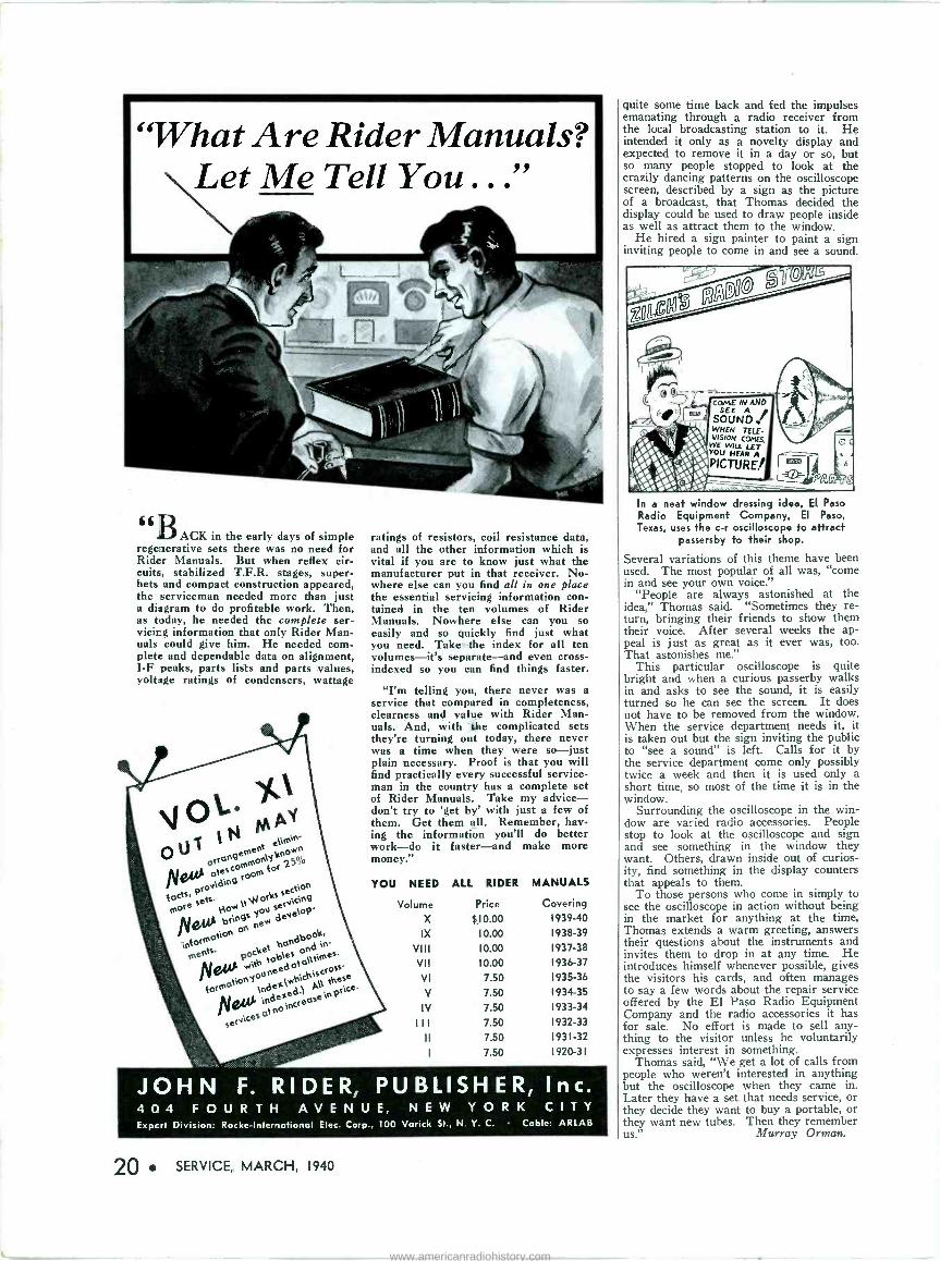
"What Are Rider Manuals? Let Me Tell You ..."
« eACK in the early days of simple rege:ierative sets there was no need for Rider Manuals. But when reflex cir- cuits, stabilized T.F.R. stages, super- hets and compact construction appeared, the serviceman needed more than just a diagram to do profitable work. Then, as today, he needed the complete ser- vicing information that only Rider Man- uals could give him. He needed com- plete and dependable data on alignment, I -F peaks, parts lists and parts values, voltage ratings of condensers, wattage
ratings of resistors, coil resistance data, and all the other information which is vital if you are to know just what the manufacturer put in that receiver. No- where else can you find all in one place the essential servicing information con- tained in the ten volumes of Rider Manuals. Nowhere else can you so easily and so quickly find just what you need. Take the index for all ten volumes-it's separate-and even cross- indexed so you can find things faster.
"I'm telling you, there never was a service that compared in completeness, clearness and value with Rider Man- uals. And, with the complicated sets they're turning out today, there never was a time when they were so-just plain necessary. Proof is that you will find practically every successful service- man in the country has a complete set of Rider Manuals. Take my advice- don't try to 'get by' with just a few of them. Get them all. Remember, hav- ing the information you'll do better work-do it faster-and make more money."
YOU NEED ALL RIDER MANUALS
Volume Price Covering
X $10.00 1939-40
IX 10.00 1938-39
VIII 10.00 1937-38
VII 10.00 1936-37
VI 7.50 1935-36
V 7.50 1934-35
IV 7.50 1933-34
III 7.50 1932-33
II 7.50 1931-32
I 7.50 1920-31
JOHN F. RIDER, PUBLISHER, Inc. 404 FOURTH AVENUE, NEW YORK CITY Expert Division: Rocke -International Elec. Corp., 100 Varick St., N. Y. C. Cable: ARLAB
20 SERVICE, MARCH, 1940
quite some time back and fed the impulses emanating through a radio receiver from the local broadcasting station to it. He intended it only as a novelty display and expected to remove it in a day or so, but so many people stopped to look at the crazily dancing patterns on the oscilloscope screen, described by a sign as the picture of a broadcast, that Thomas decided the display could be used to draw people inside as well as attract them to the window.
He hired a sign painter to paint a sign inviting people to come in and see a sound.
COME IN AND SEE A
SOUND WHEN TELE- VISION CONES,
WE WILL LET YOU HEAR A
PICTURE/
In a neat window dressing idea, EI Paso Radio Equipment Company, EI Paso, Texas, uses the c -r oscilloscope to attract
passersby to their shop.
Several variations of this theme have been used. The most popular of all was, "come in and see your own voice."
"People are always astonished at the idea," Thomas said. "Sometimes they re- turn, bringing their friends to show them their voice. After several weeks the ap- peal is just as great as it ever was, too. That astonishes me."
This particular oscilloscope is quite bright and when a curious passerby walks in and asks to see the sound, it is easily turned so he can see the screen. It does not have to be removed from the window. When the service department needs it, it is taken out but the sign inviting the public to "see a sound" is left. Calls for it by the service department come only possibly twice a week and then it is used only a short time, so most of the time it is in the window.
Surrounding the oscilloscope in the win- dow are varied radio accessories. People stop to look at the oscilloscope and sign and see something in the window they want. Others, drawn inside out of curios- ity, find something in the display counters that appeals to them.
To those persons who come in simply to see the oscilloscope in action without being in the market for anything at the time, Thomas extends a warm greeting, answers their questions about the instruments and invites them to drop in at any time. He introduces himself whenever possible, gives the visitors his cards, and often manages to say a few words about the repair service offered by the El Paso Radio Equipment Company and the radio accessories it has for sale. No effort is made to sell any- thing to the visitor unless he voluntarily expresses interest in something.
Thomas said, "We get a lot of calls from people who weren't interested in anything but the oscilloscope when they came in. Later they have a set that needs service, or they decide they want to buy a portable, or they want new tubes. Then they remember us." Murray Orman.
www.americanradiohistory.com
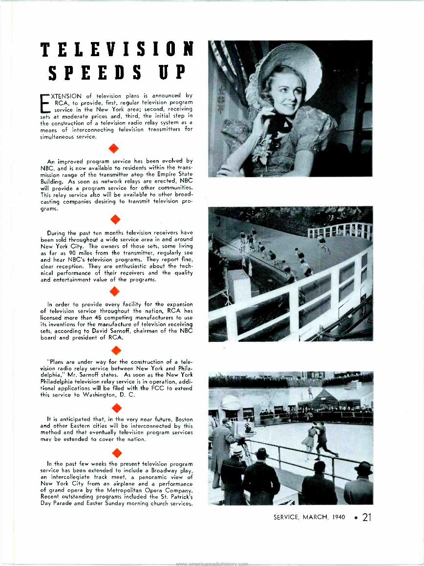
TELEVISION SPEEDS UP EXTENSION of television plans is announced by
RCA, to provide, first, regular television program service in the New York area; second, receiving
sets at moderate prices and, third, the initial step in
the construction of a television radio relay system as a
means of interconnecting television transmitters for simultaneous service.
An improved program service has been evolved by
NBC, and is now available to residents within the trans- mission range of the transmitter atop the Empire State Building. As soon as network relays are erected, NBC will provide a program service for other communities. This relay service also will be available to other broad- casting companies desiring to transmit television pro- grams.
During the past ten months television receivers have been sold throughout a wide service area in and around New York City. The owners of those sets, some living as far as 90 miles from the transmitter, regularly see
and hear NBC's television programs. They report fine, clear reception. They are enthusiastic about the tech- nical performance of their receivers and the quality and entertainment value of the programs.
In order to provide every facility for the expansion of television service throughout the nation, RCA has licensed more than 45 competing manufacturers to use its inventions for the manufacture of television receiving sets, according to David Sarnoff, chairman of the NBC board and president of RCA.
"Plans are under way for the construction of a tele- vision radio relay service between New York and Phila- delphia," Mr. Sarnoff states. As soon as the New York Philadelphia television relay service is in operation, addi- tional applications will be filed with the FCC to extend this service to Washington, D. C.
It is anticipated that, in the very near future, Boston and other Eastern cities will be interconnected by this method and that eventually television program services may be extended to cover the nation.
In the past few weeks the present television program service has been extended to include a Broadway play, an intercollegiate track meet, a panoramic view of New York City from an airplane and a performance of grand opera by the Metropolitan Opera Company. Recent outstanding programs included the St. Patrick's Day Parade and Easter Sunday morning church services.
SERVICE, MARCH, 1940 21
www.americanradiohistory.com
Forty-seven members of RCA among 572 industrial engineers and scientists given awards as "Modern Pioneers on
American Frontiers of Industry."
SINCE its beginning, the Radio Corporation of
America has held that Research in all fields
of radio and sound is one of its major obligations
to the public and to the future of radio.
Research is the keystone of every operation of
RCA. RCA Laboratories are the fountain head of
many of the spectacular radio and electronic de-
velopments of the past twenty years.
Back of these developments ...back of the term
Research, in fact...are men. Men make discover-
ies. And we at RCA are extremely proud of the
man -power which has elevated RCA Research to
a position of leadership.
We wish to add our own congratulations to the
public recognition these men have already re-
ceived. And, in addition, we extend equally warm
congratulations to the many other RCA engineers
and scientists whose brilliant work is contributing
so much to the progress of their industry.
RCA Manufacturing Company, Inc. National Broadcasting Company RCA Laboratories R.C.A. Communications, Inc. RCA Institutes, Inc. Radiomarine Corporation of America
L% SERVICE, MARCH 1940
e.¡Yv
www.americanradiohistory.com
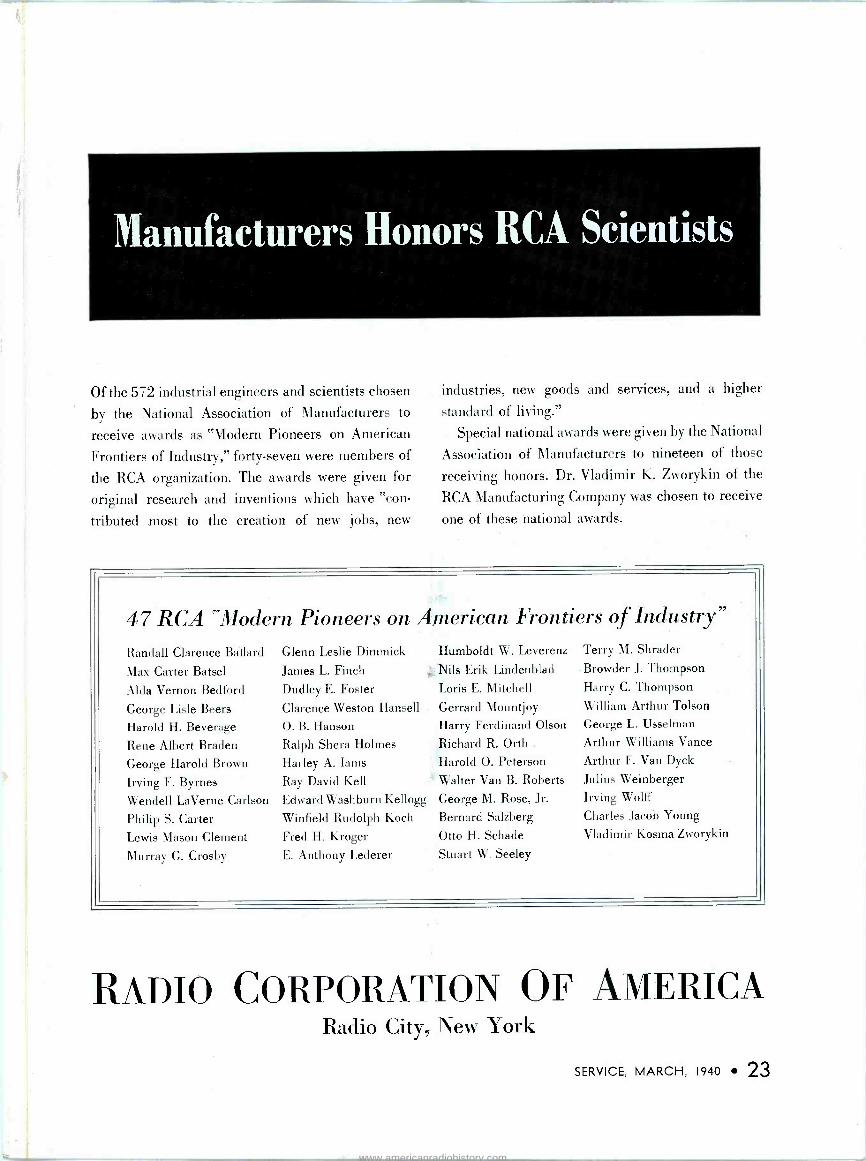
Manufacturers Honors RCA Scientists
Of the 572 industrial engineers and scientists chosen
by the National Association of Manufacturers to
receive awards as "Modern Pioneers on American
Frontiers of Industry," forty-seven were members of
the RCA organization. The awards were given for
original research and inventions which have "con-
tributed most to the creation of new jobs, new
industries, new goods and services, and a higher
standard of living."
Special national awards were given by the National
Association of Manufacturers to nineteen of those
receiving honors. Dr. Vladimir K. Zworykin of the
RCA Manufacturing Company was chosen to receive
one of these national awards.
47 RCA "Modern Pioneers on American Frontiers of Industry"
Randall Clarence Ballard
Max Carter Batsel
Alda Vernon Bedford
George Lisle Beers
Harold H. Beverage
Rene Albert Braden
George Harold Brown
Irving F. Byrnes
Wendell LaVerne Carlson
Philip S. Carter Lewis Mason Clement
Murray G. Crosby
Glenn Leslie Dimmick
James L. Finch
Dudley E. Foster
Clarence Weston Hansell O. B. Hanson
Ralph Shera Holmes Harley A. Iams
Ray David Kell
Edward Washburn Kellogg
Winfield Rudolph Koch
Fred H. Kroger
E. Anthony Lederer
Humboldt W. Leverenz
Nils Erik Lindenblad
Loris E. Mitchell
Gerrard Mountjoy Harry Ferdinand Olson
Richard R. Orth Harold O. Peterson
Walter Van B. Roberts
George M. Rose, Jr.
Bernard Salzberg
Otto H. Schade
Stuart W. Seeley
Terry M. Shrader
Browder J. Thompson
Harry C. Thompson
William Arthur Tolson
George L. Usselman
Arthur Williams Vance
Arthur F. Van Dyck
Julius Weinberger
Irving Wolff
Charles Jacob Young
Vladimir Kosma Zworykin
RADIO CoRPoRATION OF AiERICA Radio City, New York
SERVICE, MARCH, 1940 23
www.americanradiohistory.com
"Good? say-that RCA Franchise is great!"
You'll call the RCA
Big Three e rte a7/ too.
A successful, progressive parts jobber is Bob Smith. When he says something is great, he speaks from experience. And he calls the RCA Franchise great!
And here are the reasons! RCA has more service experience in every field of radio and sound than has any other organization. This enables RCA to design test equipment which answers every need in the field. Obsolescence is minimized because RCA makes the trends in radio ... and knows far in advance what the trends will be.
RCA developed the receiving tube business ... and no one else has caught up yet. The tubes America knows best are easiest to sell.
Not only does RCA offer types of Power Tubes that no one else makes ... but RCA also knows the tube requirements of transmitters as few can because RCA makes transmitters.
When you think it over, you can't help but agree ... It Pays to Go RCA All the Way. Over 335 million RCA Radio Tubes have been purchased by radio users ... in tubes, as in parts and test equipment, it pays
to go RCA All the Way.
eafr
says -i () > n ; d1 RADIO LAB, KANSAS CITY, MO.
"Our business is pretty much dependent on sales of test equipment, receiving tubes and power tubes. And with the RCA Big Three it's a profit- able business because RCA makes the outstand- ing products in each field. The RCA Franchise is better than good. It's great!"
Only RCA Offers You All Three TEST EQUIPMENT RECEIVING TUBES
POWER TUBES (T':ir..^mitting, Cathode Ray, and Special Purpose Tubes)
sonnt r+ 1--,=
7-iia g 7-47-44WW- RCA Manufacturing Company, Inc., Camden, New Jersey
24 SERVICE, MARCH, 1940
A Service of the Radio Corporation of America
www.americanradiohistory.com
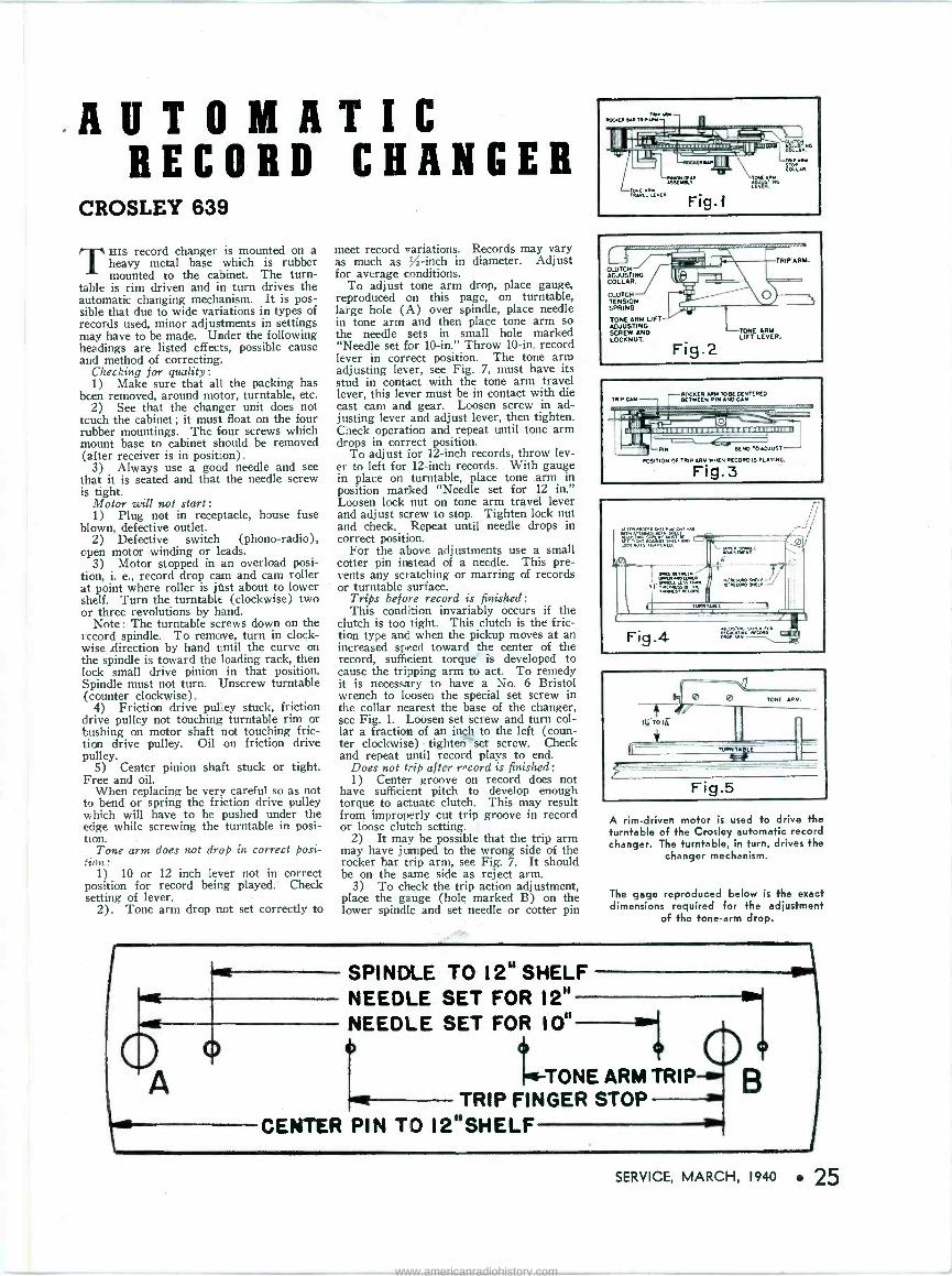
AUTOMATIC RECORD CHANGER
CROSLEY 639
THIS record changer is mounted on a heavy metal base which is rubber mounted to the cabinet. The turn-
table is rim driven and in turn drives the automatic changing mechanism. It is pos- sible that due to wide variations in types of records used, minor adjustments in settings may have to be made. Under the following headings are listed effects, possible cause and method of correcting.
Checking for quality: 1) Make sure that all the packing has
been removed, around motor, turntable, etc. 2) See that the changer unit does not
tcuch the cabinet ; it must float on the four rubber mountings. The four screws which mount base to cabinet should be removed (after receiver is in position).
3) Always use a good needle and see that it is seated and that the needle screw is tight.
Motor will not start: 1) Plug not in receptacle, house fuse
blown, defective outlet. 2) Defective switch (phono -radio),
open motor winding or leads. 3) Motor stopped in an overload posi-
tion, i. e., record drop cam and cam roller at point where roller is just about to lower shelf. Turn the turntable (clockwise) two or three revolutions by hand.
Note : The turntable screws down on the record spindle. To remove, turn in clock- wise direction by hand until the curve on the spindle is toward the loading rack, then lock small drive pinion in that position. Spindle must not turn. Unscrew turntable (counter clockwise).
4) Friction drive pulley stuck, friction drive pulley not touching turntable rim or bushing on motor shaft not touching fric- tion drive pulley. Oil on friction drive pulley.
5) Center pinion shaft stuck or tight. Free and oil.
When replacing be very careful so as not to bend or spring the friction drive pulley which will have to be pushed under the edge while screwing the turntable in posi- tion. .
Tone arm does not drop in correct posi- tion:
1) 10 or 12 inch lever not in correct position for record being played. Check setting of lever.
2). Tone arm drop not set correctly to
meet record variations. Records may vary as much as %-inch in diameter. Adjust for average conditions.
To adjust tone arm drop, place gauge, reproduced on this page, on turntable, large hole (A) over spindle, place needle in tone arm and then place tone arm so the needle sets in small hole marked "Needle set for 10 -in." Throw 10 -in. record lever in correct position. The tone arm adjusting lever, see Fig. 7, must have its stud in contact with the tone arm travel lever, this lever must be in contact with die cast cam and gear. Loosen screw in ad- justing lever and adjust lever, then tighten. Check operation and repeat until tone arm drops in correct position.
To adjust for 12 -inch records, throw lev- er to left for 12 -inch records. With gauge in place on turntable, place tone arm in position marked "Needle set for 12 in." Loosen lock nut on tone arm travel lever and adjust screw to stop. Tighten lock nut and check. Repeat until needle drops in correct position.
For the above adjustments use a small cotter pin instead of a needle. This pre- vents any scratching or marring of records or turntable surface.
Trips before record is finished: This condition invariably occurs if the
clutch is too tight. This clutch is the fric- tion type and when the pickup moves at an increased speed toward the center of the record, sufficient torque" is developed to cause the tripping arm to act. To remedy it is necessary to have a No. 6 Bristol wrench to loosen the special set screw in the collar nearest the base of the changer, see Fig. 1. Loosen set screw and turn col- lar a fraction of an in. to the left (coun- ter clockwise) tighten set screw. Check and repeat until record plays to end.
Does not trip after r"cord is finished: 1) Center groove on record does not
have sufficient pitch to develop enough torque to actuate clutch. This may result from improperly cut trip groove in record or loose clutch setting.
2) It may be possible that the trip arm may have jumped to the wrong side of the rocker bar trip arm, see Fig. 7. It should be on the same side as reject arm.
3) To check the trip action adjustment, place the gauge (hole marked B) on the lower spindle and set needle or cotter pin
r
ADJUSTING COLLAR.
CLUTCH TENSION SPRING.
TONE ARM LIFT ADJUSTING SCREW AND LOCANUT-
Fig.2
TRIP ARM.
TONE ARM LIFT LEVER.
TRIP CAM ROCKER ARM TO BE CENTCRED BETWEEN PIN AND CAM
T . id
--v 11R111I1
Ih
ml PIN BEND TOA0.IUST--
POSITION OF TRIP ARM *MEN RECORD IS PLAYING.
Fig.3
A rim -driven motor is used to drive the turntable of the Crosley automatic record changer. The turntable, in turn, drives the
changer mechanism.
The gage reproduced below is the exact dimensions required for the adjustment
of the tone -arm drop.
SPINDLE TO 12u SHELF NEEDLE SET FOR 1 2 NEEDLE SET FOR IO"
to-TONE ARM TRIP TRIP FINGER STOP
CENTER PIN TO 12"SHELF
SERVICE, MARCH, 1940 25
www.americanradiohistory.com
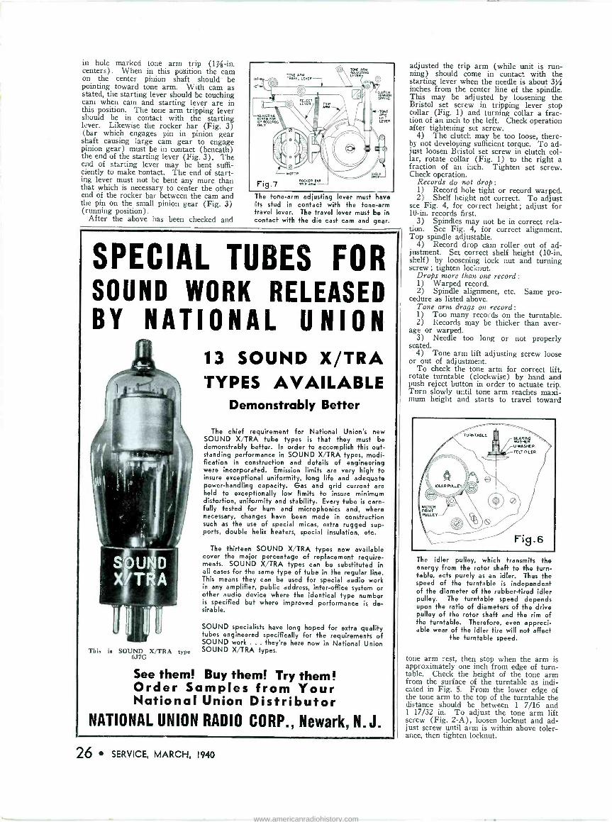
in hole marked tone arm trip (1% -in. centers). When in this position the cam on the center pinion shaft should be pointing toward tone arm. With cam as stated, the starting lever should be touching cani when cam and starting lever are in this position. The tone arm tripping lever should be in contact with the starting lever. Likewise the rocker bar (Fig. 3) (bar which engages pin in pinion gear shaft causing large cam gear to engage pinion gear) must be in contact (beneath) the end of the starting lever (Fig. 3). The end of starting lever may be bent suffi- ciently to make Contact. The end of start- ing lever must not be bent any more than that which is necessary to center the other end of the rocker bar between the cam and the pin on the small pinion gear (Fig. 3) (running position).
After the above has been checked and
The tone -arm adjusting lever must have its stud in contact with the tone -arm travel lever. The travel lever must be in contact with the die cast cam and gear.
SPECIAL TUBES FOR SOUND WORK RELEASED BY NATIONAL UNION
This is SOUND X/TRA type 6J7G
13 SOUND X/TRA TYPES AVAILABLE
Demonstrably Better
The chief requirement for National Union's new SOUND X/TRA tube types is that they must be demonstrably better. In order fo accomplish this out- standing performance in SOUND X/TRA types, modi- fication in construction and details of engineering were incorporated. Emission limits are very high to insure exceptional uniformity, long life and adequate power -handling capacity. Gas and grid current are held to exceptionally low limits to insure minimum distortion, uniformity and stability. Every tube is care- fully tested for hum and microphonics and, where necessary, changes have been made in construction such as the use of special micas, extra rugged sup- ports, double helix heaters, special insulation, etc.
The thirteen SOUND X/TRA types now available cover the major percentage of replacement require- ments. SOUND X/TRA types can be substituted in all cases for the same type of tube in the regular line. This means they can be used for special audio work in any amplifier, public address, interoffice system or other audio device where the identical type number is specified but where improved performance is de- sirable.
SOUND specialists have long hoped for extra quality tubes engineered specifically for the requirements of SOUND work ... they're here now in National Union SOUND X/TRA types.
See them! Buy them! Try them! Order Samples from Your National Union Distributor
NATIONAL UNION RADIO CORP., Newark, N.J.
26 SERVICE, MARCH, 1940
adjusted the trip arm (while unit is run- ning) should come in contact with the starting lever when the needle is about 3/ inches from the center line of the spindle. This may be adjusted by loosening the Bristol set screw in tripping lever stop collar (Fig. 1) and turning collar a frac- tion of an inch to the left. Check operation after tightening set screw.
4) The clutch may be too loose, there- by not developing sufficient torque. To ad- just loosen Bristol set screw in clutch col- lar, rotate collar (Fig. 1) to the right a fraction of an inch. Tighten set screw. Check operation.
Records do not drop: 1) Record hole tight or record warped. 2) Shelf height not correct. To adjust
see Fig. 4, for correct height; adjust for 10 -in. records first.
3) Spindles may not be in correct rela- tion. See Fig. 4, for correct alignment. Top spindle adjustable.
4) Record drop cam roller out of ad- justment. Set correct shelf height (10 -in. shelf) by loosening lock nut and turning screw ; tighten locknut.
Drops more than one record: 1) Warped record. 2) Spindle alignment, etc. Same pro-
cedure as listed above. Tone arm drags on record: 1) Too many records on the turntable. 2) Records may be thicker than aver-
age or warped. 3) Needle too long or not properly
seated. 4) Tone arm lift adjusting screw loose
or out of adjustment. To check the tone arm for correct lift,
rotate turntable (clockwise) by hand and push reject button in order to actuate trip. Turn slowly until tone arm reaches maxi- mum height and starts to travel toward
The idler pulley, which transmits the energy from the rotor shaft to the turn- table, acts purely as an idler. Thus the speed of the turntable is independent of the diameter of the rubber -tired idler pulley. The turntable speed depends upon the ratio of diameters of the drive pulley of the rotor shaft and the rim of the turntable. Therefore, even appreci- able wear of the idler tire will not affect
the turntable speed.
tone arm rest, then stop when the arm is approximately one inch from edge of turn- table. Check the height of the tone arm from the surface of the turntable as indi- cated in Fig. 5. From the lower edge of the tone arm to the top of the turntable the distance should be between 1 7/16 and 1 17/32 in. To adjust the tone arm lift screw (Fig. 2-A), loosen locknut and ad- just screw until arm is within above toler- ance, then tighten locknut.
www.americanradiohistory.com

BOOK REVIEWS. RADIO'S MASTER ENCYCLOPEDIA,
published by United Catalog Pub- lishers, Inc., 230 Fifth Ave., New York City, 812 pages, 7/ by 10% in., price $2.50 net.
This book is somewhat misnamed, since it is in reality a master catalog and not an encyclopedia.
It is comprised of five separate sections :
(1) Index of Manufacturers' Display Pages, which lists the manufacturers in- cluded in the book alphabetically. This is useful in order to locate the different prod- ucts of a particular manufacturer who makes a number of different products. (2) Classified Directory, which is customarily called a buyers' guide. This tabulates the various manufacturers who make specific equipment, such as amplifiers, generators, hardware, microphones, wire, etc. Although this section is, in the reviewer's opinion, the most valuable portion of the book, it is, nevertheless, full of errors both of com- mission and omission. To cite but a single case, the field of Hearing Aids is com- pletely ignored. Notwithstanding the pre- ceding indictment, it is probably the most complete buyers' guide readily available. It is for this reason, therefore, and for this reason only, that the exorbitant price asked for this book has any justification. (3) In- dex of Trade Names, Trade Marks, etc. This section, as its heading indicates, en- ables the user of this book to readily deter- mine the name of the manufacturer when only the trade name of the product is known. (4) Catalog Section. This section, which comprises the major part of the book, is a reprint of the catalogs of a large number of manufacturers. It is arranged according to types of products, for exam- ple, vacuum tubes, loudspeakers, phono- graph pickups, meters and testing equip- ment, condensers, transformers, etc. This section should prove very useful for it encompasses within the confines of a single volume a large number of manufacturers' catalogs, which would otherwise occupy a considerable amount of space. Although quite comprehensive in the number of manufacturers included, it is, of necessity, far from complete. This latter would not be too great a defect were it not for the fact that some of the most important manu- facturers in the field are not included. (5) General Index. This section alphabetically tabulates both products and manufacturers.
At the bottom of each page the discount ordinarily available from the list prices indicated is given inconspicuously in sim- ple code. D. B.
PHILCO 1939 RMS YEAR BOOK, pub- lished by the Philco Radio & Television Corp., Tioga and C Sts., Philadelphia, Pa., 1939, 120 pages 8% by 11 in., pa- per covers, price 75e.
This book is a complete service sum- mary on 1939 Philco receivers and con- tains information and circuits of every model introduced during the 1939 season. It covers home radio sets, auto -radio sets, combinations and automatic record changers. Instructions are given for set- ting push buttons, aligning sets and for using the vacuum -tube voltmeter for mod- ern service work. The book contains com- plete schematic diagrams, chassis layouts, tuning mechanism data, production changes and replacement parts lists.
Because of the great number of Philco receivers in daily use, it is this reviewer's opinion that this book is a necessity to every Service Man. R. H.
Bob Lehfeldt of Flagler Radio Co., Miami, reports that a high-powered, high-fidelity ampli- fier plus twenty Atlas G8 Super - Power Cone Projec- tors offers effective distribution and complete coverage of Dixie's Orange
Bowl.
Lehfeldt experi- mented with various types of projectors before deciding on the cone size trum- pets.
5l .,4
Typical SPRAGUE VALUES
SAVE MONEY ON RESISTORS.... You can get the resistance value in a Sprague
5 -watt Koolohm that would require the purchase of a 10 -watt old-style resistor. You can't break down Sprague Koolohms-+hey take the overloads. Every bit of wire is insulated before winding. Units are layer -wound for more ohms in smaller size. Non - inductive Koolohms sold at lowest prices ever. Tele -dot automatic overload indicator warns when 25 %overload occurs (see picture) .
Ask your Jobber about this amazing Sprague resistor development!
SPRAGUE TEL-OHMIKE Condenser -Resistor Analyzer
NET COST $29.70
SPRAGUE KOOLOHM WIRE WOUND RESISTORS
SAVE MONEY ON INSTRUMENTS .... Don't buy meters twice! Get a Sprague Tel-Ohmike Con-
denser -Resistor Analyzer, plug in your own voltmeter and milliammeter-and you have an instrument worth at least $50. Tel-Ohmike does more-and does it better-than any other instrument of its kind. Tests all capacities, intermittent opens, power factor, leakage, insulation resistance and resistance values at all voltages. It is an instrument you need every day-and one designed for long, obsolescence -proof service. Ask your jobber. Bulletin free.
MAKE MONEY on RADIO INTERFERENCE ELIMINATION . .
This is the book you've been waiting for - the Sprague Man- ual of Radio Interference ® Elimination.
25t net Fully illustrat- (direct or from
e d -cover s Sprague jobbers) every phase
of the work. Tells exactly what to do and how to do it.
SAVE MONEY ON CONDENSERS .... Sprague Atoms (midget dry electro-
lytics) replace old-style condensers, many times larger in size and costing a great deal more. You save money, you save space-and you save time. A few handy Atom Kits will equip you for 75% of all dry electrolytic replace- ments. Atoms are the smallest midgets on the market-and made in the mos+ complete line of single and duals. Unconditionally guaranteed. An 8-mfd. 450-v. Atom costs you only 36¢ net. Other capacities proportionately low in
price.
SPRAGUE SPRAGUE PRODUCTS CO.
SPRAGUE ATOMS Mightiest Midgets of All
CONDENSERS
KOOLOHM RESISTORS
TEST EQUIPMENT NORTH ADAMS. MASS.
SERVICE, MARCH, 1940 27
www.americanradiohistory.com
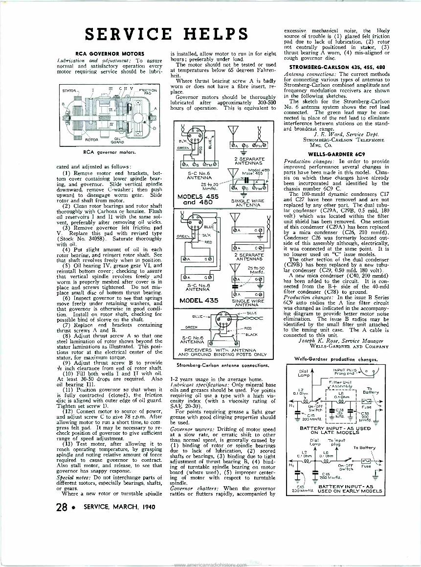
SERVICE HELPS RCA GOVERNOR MOTORS
Lubrication and adjustment: To assure normal and satisfactory operation every motor requiring service should be lubri-
RCA governor motors.
cated and adjusted as follows :
(1) Remove motor end brackets, bot- tom cover containing lower spindle bear- ing, and governor. Slide vertical spindle downward, remove C -washer ; then push upward to disengage worm gear. Slide rotor and shaft from motor.
(2) Clean rotor bearings and rotor shaft thoroughly with Carbona or benzine. Flush oil reservoirs I and II with the same sol- vent, preferably after removing oil wicks.
(3) Remove governor felt friction pad V. Replace this pad with revised type (Stock No. 34058). Saturate thoroughly with oil.
(4) Put slight amount of oil in each rotor bearing, and reinsert rotor shaft. See that shaft revolves freely when in position.
(5) Oil bearing IV, grease gear VI, and reinstall bottom cover; checking to assure that vertical spindle revolves freely and worm is properly meshed after cover is in place and screws tightened. Do not mis- place small disc of bottom thrust bearing.
(6) Inspect governor to see that springs move freely under retaining washers, and that governor is otherwise in good condi- tion. Install on rotor shaft, checking for possible bind of sleeve on the shaft.
(7) Replace end brackets containing thrust screws A and B.
(8) Adjust thrust screw A so that one steel lamination of rotor shows beyond the stator laminations as illustrated. This posi- tions rotor at the electrical center of the stator, for maximum torque.
(9) Adjust thrust screw B to provide is inch clearance from end of rotor shaft.
(10) Fill both wells I and II with oil. At least 30-50 drops are required. Also oil bearing III.
(11) Position governor so that when it is fully contracted (closed), the friction disc is aligned with outer edge of oil guard. Tighten set screw D.
(12) Connect motor to source of power, and adjust screw C to give 78 r.p.m. After allowing motor to run a short time, to com- press felt pad. It may be necessary to re- check position of governor to give sufficient range of speed adjustment.
(13) Test motor, after allowing it to reach operating temperature, by grasping spindle and noting relative amount of force required to cause governor to contract. Also stall motor, and release, to see that governor has snappy response. Special notes: Do not interchange parts of different motors, especially bearings, shafts, or gears.
Where a new rotor or turntable spindle
28 SERVICE, MARCH, 1940
is installed, allow motor to run in for eight hours; preferably under load.
The motor should not be tested or used at temperatures below 65 degrees Fahren- heit.
Where thrust bearing screw A is badly worn or does not have a fibre insert, re- place.
Governor motors should be thoroughly lubricated after approximately 300-500 hours of operation. This is equivalent to
S -C No.6 ANTENNA
25 +o 50 ---- Mmfd.
MODELS 455 and 480
J 2 SEPARATE ANTENNAS
Model 480 Model 455
1
t
SINGLE WIRE ANTENNA
BLUE
BL'K
"RED
S -C No.6 ANTENNA
MODEL 435
2 SEPARATE ANTENNAS
SINGLE WIRE ANTENNA
©LuL-
GREEN
S -C No.6 ANTENNA
E ---BLUE
_- RED
---BLACK
RECEIVERS WITH ANTENNA AND GROUND BINDING POSTS ONLY
Stromberg -Carlson antenna connections.
1-2 years usage in the average home. Lubricant specifications: Only mineral base oils and greases should be used. For points requiring oil use a type with a high vis- cosity index (with a viscosity rating of SAE 20-30).
For points requiring grease a light gear grease with good clinging properties should be used. Governor wavers: Drifting of motor speed at a slow rate, or erratic shift to other than normal speed, is generally caused by (1) binding of rotor or spindle bearings due to lack of lubrication, (2) scored shafts or bearings, (3) binding due to tight adjustment of thrust bearing B, (4) bind- ing of turntable spindle bearing on motor board (where used), (5) improper center- ing of motor with respect to turntable spindle. Governor chatters: When the governor rattles or flutters rapidly, accompanied by
excessive mechanical noise, the likely source of trouble is (1) glazed felt friction pad due to lack of lubrication, (2) rotor not centrally positioned in stator, (3) thrust bearing A worn, (4) mis -aligned or rough governor disc.
STROMBERG-CARLSON 435, 455. 480 Antenna connections: The correct methods for connecting various types of antennas to Stromberg -Carlson combined amplitude and frequency modulation receivers are shown in the following sketches.
The sketch for the Stromberg -Carlson No. 6 antenna system shows the red lead connected. The green lead may be con- nected in place of the red lead to eliminate interference between stations on the stand- ard broadcast range.
J. E. Ward, Service Dept. STROMBERG-CARLSON TELEPHONE
MFG. Co.
WELLS-GARDNER 6C9 Production changes: In order to provide improved performance several changes in parts have been made in this model. Chas- sis on which these changes have already been incorporated and identified by the chassis number 6C9 C.
The 100-mmfd dynamic condensers C17 and C27 have been removed and are not replaced by any other part. The dual tubu- lar condenser (C29A, C29B, 0.5 mfd, 180 volt) which was located within the filter unit shield has been removed. One section of this condenser (C29A) has been replaced by a mica condenser (C26, 210 mmfd). Condenser C26 was formerly located out- side of this assembly although, electrically, it was connected at the same point. It is no longer used on "C" issue models.
The other section of the dual condenser (C29B) has been replaced by a new tubu- lar condenser (C29, 0.50 mfd, 180 volt).
A new mica condenser (C40, 200 mmfd) has been added to the circuit. It is con- nected from the B -i- side of the 40-mfd filter condenser (C28) to ground. Production changes: In the issue B Series 6C9 auto radios the A line filter circuit was changed as indicated in the accompany- ing diagram to provide better motor noise elimination. The issue B radios may be identified by the small filter unit attached to the tuning unit case. The A cable is connected to this unit.
Joseph K. Rose, Service Manager WELLS-GARDNER AND COMPANY
Wells -Gardner produc+ion changes.
Dial Lan,p
INPUT PLUG Prong end
Filter Unit (Assembly
To L 0.4 Ohm I L8 I
I 0.1 Ohm
OnÓff 9Qc39 Switch
1
C38 I 00 Mmfd. Ì
Mfd I 1 \ 200 , Mmfd.
11
BATTERY INPUT-AS USED ON LATE MODELS
Dial Lamp
To input plug
To Battery L2 L6
0.1 Ohm 0.1 Ohm
On -Off Switch
Fuse
C16 200 Mmfd.
i C15 BATTERY INPUT- AS
200Mmfd. USED ON EARLY MODELS
www.americanradiohistory.com
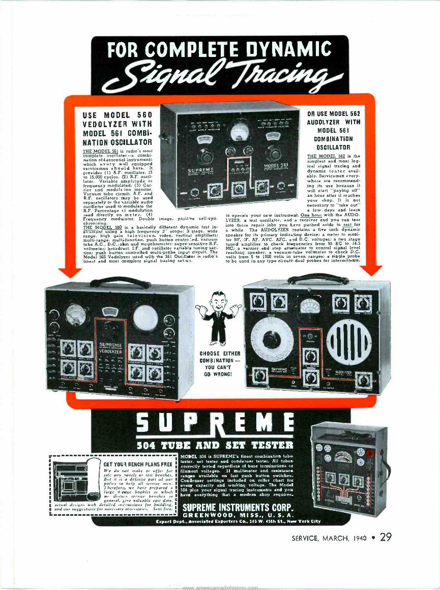
r
L
FOR COMPLETE DYNAMIC
USE MODEL 560 VEDOLYZER WITH MODEL 561 COMBI-
NATION OSCILLATOR THE MODEL 561 is radio's most complete oscillator-a combi- nation of4essential instruments which every w Al equipped serviceman should have. It provides (I) A.F. oscillator, 15 to 15.000 cycles. (2) R.F. oscil- lator. Variable amplitude or frequency modulated. (3) Car- rier and modula ion monitor. Vacuum tube circuit. A.F. and +s R.F. oscillators may be used separately or the variable audio oscillator used to modulate the R.F. Percentage cf modulation read directly on meter. (4) Frequency modu_ator. Double image, posit ve self -syn- chronizing. THE MODEL 560 is a basically different dynamic test in- strument using a high frequency 3" scope; 3 stage, wide range, high gain television, video, vertical amplifiers; multi -range, multi -function. push button contro :ed, vacuum tube A.C., D.C., ohm and megohmmeter; super -sensitive R.F. voltmeter; broadcast, I.F. and oscillator variable tuning sec- tion; push button controlled multi probe input circuit. The Model 560 Vedolyzer used with the 561 Oscillator is radio's
'finest and most complete signal tracing set -u -J.
cftJpREME
OR USE MODEL 562
AUDOLYZER WITH
MODEL 561
COMBINATION
OSCILLATOR
THE MODEL 562 is the iYaüe simplest and most log-
ical signal tracing and dynamic tester avail- able. Servicemen every- where are recommend- ing
.''. . its use becauseit
will start "payingingoff" an hour after it reaches your shop. It is not necessary to "take out" a few days and learn
to operate your new instrument. One hour with the AUDO- LYZER, a test oscillator, and a receiver and you can tear into those repair jobs you lave pushed aside to rest for a while. The AUDOLYZER _ontains a five inch dynamic speaker for its primary indicating device; a meter to moni- tor RF, :F, AF, AVC. AFC, and D.C. voltages: a two stage tuned amplifier to check frequencies from 95 KC to 14.5 MC; a vernier and step attenuator to control signal level reaching speaker; a vacuum -tube voltmeter to check D.C. volts from 0 to 1000 volts in seven ranges; a single probe to be used in any type circuit- dual probes for intermittents.
CHOOSE EITHER
COMBINATION - YOU CAN'T
GO WRONG!
MO Lt£L 56t
504 TUBE AND SET TESTER
GET YOU BENCH PLANS FREE
We do rot make or offer for sale any ,anels or test benches. But it is a definite part of our policy to help all service men. Therefore. we have prepared a
large 4 -page booklet in which we discuss service benches in general, ire valuable cost data,
actual designs with detailed ins'ructions for building. and our suggestions for necessary accessories. Sent free.
MOREL 504 is SUPREME's finest combination tube tester, set tester and condeaser tester. All tubes corrsetly tested regardless of base terminations or filament voltages. 31 multimeter and resistance ranges available on fast push button switches. Conienser settings included on roller chart for every capacity and working voltage. The Model 504 plus your signal tracing instruments and you have everything that a modern shop requires.
SUPREME INSTRUMENTS CORP. GREENWOOD, MISS., U. S. A.
Export Dept., tassociated Exporters Co., 145 W. 45th St., Neer York City
SERVICE, MARCH, 1940 29
www.americanradiohistory.com
ASSOCIATIONS RADIO SERVICEMEN OF AMERICA
THE RSA is pleased to announce the application for the forma- tion of another chapter of RSA
In Milwaukee, Wis. Joe Marty, Jr., executive secre-
tary, has returned from a 7,000 mile trip around the chapter terri- tories of the RSA in the middlewest and throughout New England and Atlantic Coast states. He reports Service Men members of the RSA enthusiastic over the possibilities for increased business during 1940, through cooperation of the NAB and the RSA.
RSA announces there are now 35 chapters throughout the country who have qualified under the Guarantee Service Plan and have further made cooperative arrangements with local broadcasters. This represents a definite step to raise the level of radio servicing on a national basis.
The results from the experimental setups of the RSA under this plan have been so gratifying that the entire membership of the RSA will be included in this plan as rapidly as conditions permit, it is said.
allentown The following officers were elected
to serve for 1940: Carl Williams, president; Joe Frey, vice-president, Bruno Ha e, secretary; J. A. Mut- hart, treasurer; Mr. Buss, Mr. Rees, and Mr. Schreiber were elected to serve on the Board of Directors. Plans are being made to have a chapter library.
The Second Annual Banquet and Test Equipment Show was held at the Hotel Allen, Allentown, Pa. Seventy-five members and their friends enjoyed the dinner and show. Movies were shown of a trip to Bali and India by Ruth and Les Seachrist, accordion team just re- turned from a World tour. The latest test equipment was displayed by several of the jobbers. Door prizes and favors were donated by these jobbers.
H. H. Fillman, Secretary
binghamton The annual election of officers of
the Binghamton Chapter saw Herby Snyder unanimously reelected presi- dent; Herb Squires was elected sec- retary and Ross Baxter, treasurer.
Herbert W. Squires, Secy. rtg, boston
TaE administrative board of the Radio Technicians Guild held a banquet at the Miles Stan-
dish Hotel, Boston, and after dinner sat in committee to formulate a com- prehensive plan designed to insure the public of dependable radio ser- vice.
The board also voted the continu- ance of affiliated groups of Radio Technicians to operate as separate from the parent guild, a system which is said to have functioned success- fully for many years.
The work of the Guild, in co- operation with local editors, radio stores, broadcasters, cannot fail to elevate the radio profession, and benefit the radio listener and set owner.
Al Saunders. boston
We had a special meeting with the Northwestern Radio Co., featuring Ray Wilson of the Zenith, who spoke on "Frequency Modulation."
The series of talks on "Set Mod- ernization" by Ray Wyman is cre- ating a great deal of interest.
Ray Wyman and Ingvar Paulsen were nominated as directors for Dis- trict 20 at a recent meeting.
The recent Banquet held by the Boston Chapter was considered an outstanding success by all those present.
Hy Leve, President
bridgeport The 1940 officers elected by the
Bridgeport Chapter were Roy Wright, president; William Pollock, vice-president; H. C. Eisenuran, treasurer; and J. T. Gomperts, sec- retary.
We are working very hard to start the NAB -RSA program in Bridge- port.
J. T. Gomperts, Secretary
cleveland Cleveland Chapter elected Rudy
Trammell chairman; Al Theriault, vice chairman; Stanley Mros, sec- retary; and Thomas B. Holmes, treasurer. L. Vangunten and James Hausser were elected trustees.
Considerable publicity has been obtained in the trade journals on the Radio Christmas. Cleveland Chapter considers it a very successful pro- motion.
Thomas B. Holmes, Secretary
danville We were host to A. G. Mohaupt
at a recent meeting, and as usual the lecture was very instructive and was enjoyed by everyone.
Cal Stapp was nominated for director for District 10.
Owen McArdle, our Program Di- rector, has for the past few meet- ings, instructed us on bookkeeping for the Service Man. After his presentation we can all realize better than ever, the real need for a system the Service Man can use.
Cal Stapp, Secretary
detroit A great deal of reorganization has
been done looking towards a more stable chapter in Detroit. The old question of a part or full time Service Man has certainly been ar- gued until the rafters ring.
We are enthusiastic about the NAB -RSA Service Plan and believe that within the next few weeks we will have all of our problems solved
The Administrative Board of the Radio Technicians Guild of Bos- ton held a banquet at the Miles Standish Hotel. Left to right: G. Batt, staff artist; J. R. Cabral, secy.; W. F. Staples, librarian; E. J. Maginot, pres.; A. C. W. Saunders, educ. director; F. Kennes, treas.; N. Baratta, asst. treas.; S. DiRusso, chale
trustees; E. Glynn, vice pros.
30 SERVICE, MARCH, 1940
and will be in a position to take advantage of this great piece of work.
Len Ross, President
duluth The first meeting of the year took
place at the Lincoln Hotel with our new president, James Springer, in charge. Discussion was centered around the NAB -RSA tie-up, com- plete details are not as yet available on results.
A very complete and interesting lecture on Ohm's law was delivered by Mr. Lindesmith.
The second meeting of the year concerned itself with the RSA an- nouncements over WEBC, the guar- antee service plan, and possible changes of some of the by-laws of our association. Carl Johnson talked on receiver distortion and held our undivided attention for a full hour.
Rudolph Luukinen, Secretary
flint We were recently host to A. G.
Mohaupt of Supreme, who gave a lecture and demonstration on the Vedolyzer. A large turnout of mem- bers were present and a number of new members signed up. We are now operating under the Guarantee Service Plan of RSA.
William F. Lutes, Secretary
fremont Honorary membership in our
chapter was awarded to Floyd Wen- ger. D. R. Bruns was nominated as a director for this district and Gene Davis of Toledo was appointed as liaison man for the Toldeo and Fremont Service Men in the NAB - RSA broadcast promotion.
D. R. Bruns, Secretary
Jamestown We are getting favorable publicity
through the Local Radio News, in their efforts to improve the status of the Service Men and to provide for Jamestown a courteous, efficient type necessary to service today's receivers.
The newly elected officers of the chapter are C. Leonard Johnson, president; Francis Samuelson, vice president; Frank Austin, secretary; and Percy Armstrong, treasurer. They were installed at the mid -winter banquet on Feb. 6.
Lawrence Babcock
jersey city The last several meetings bave
concerned themselves with the busi- ness of advertising and qualifying Service Men under the NAB -RSA Guarantee Service Plan. Several new members were qualified and accepted into the membership.
We had as our guest Carl Rauher, director of our district, who gave us a very interesting talk on classi- fication of Service Men in relation to the NAB campaign. We are looking forward to greatly increased business as a result of this campaign.
Frank Johnson, Secretary
minneapolis We had a very successful Radio
Christmas promotion with splendid cooperation from the broadcasting stations. The public responded be- yond our highest hope. We have been so busy lately that we have had to pass up our regular business meetings. We are looking. forward to 1940 with more enthusiasm than any year we can remember.
Sears Milnor, Secretary
newark The last several meetings have
concerned themselves almost entirely with the technical details necessary to put into operation the NAB -RSA Service Plan. Because chapters in the New York area are operating as a region, a tremendous amount of detail is involved. We have had to reclassify all of our members in order that we could take advantage of this plan. An employment service is planned for our members and a Budgeting Committee was appointed to work out a budget for the coming year.
Carl Rauher, our president and
national director, was elected as sec- retary of the regional broadcast pro- motion board.
We were guests of the Radio Club of America at a recent talk on "Wide Band Frequencies via Coaxial Cable".
Al Fasanello, Secretary
new york New officers for 1940 were elected
as follows: George F'. Duvall, presi- dent; F. Cassidy, first vice president; J. W. Stuber, second vice president; S. Rosengarten, secretary; and H. M. Guthman, treasurer.
Bob Herzog, Editor of Service, continued his series of Service Forums on "Circuit Constants". John Meagher, RCA Service Engineer, gave a very fine demonstration using the RCA Dynamic Demonstrator and Rider's Chanalyst.
Beer and sandwiches were served at a get-together on Jan. 29. Mem- bers exchanged a number of inter- esting stories, Mr. Guthman pre sented moving pictures, and Mr. Hinkelbein of the Westchester Chap- ter came with his violin and alter- nating with Mr. Stuber at the piano, rendered a variety of popular airs.
S. Rosengarten, Secretary
pontiac A recent visitor to our chapter was
Joe Marty, executive secretary of RSA, who gave us full details and instructions of our operation under the Guarantee Service Plan. Come plete cooperation was secured from the local broadcasters.
S. W. Christie, Secretary
st. paul The following officers were elected
for 1940: Fred Melius, president; Noel Granger, vice president; and Charles Fox, secretary -treasurer.
We have increased our member- ship by the application of several new members recently and are co- operating with Minneapolis in the NAB -RSA promotion in the Twin Cities area.
Charles W. Fox, Secretary
Scranton Officers elected for 1940 are
Adolph Oschmann, president; Vin- cent Zurblis, vice president; Olin Van Fleet, secretary; and eorge Wilson, treasurer. Olin Van Fleet was nominated for the post of Na- tional Director for the sixteenth dis- trict. The Scranton broadcasters and the Scranton Electric Co. were voted honorary members of our chapter in appreciation of their cooperation with us. We value very highly the spot announcements which WGBI has given us under the Guarantee Ser- vice Plan.
Vincent Zurblis, Vice President springfield
We held a special meeting, Jan. 31, in order that we could hear A. G. Mohaupt of Supreme, lecture on the Supreme Vedolyzer.
We have elected the following officers for 1940: Kenneth Beatty. president; Arthur Milner, vice presi- dent; Ray Westerfield, secretary - treasurer.
We are starting two study courses-one in elementary electricity and radio, and one in advanced radio and television. We are trying a new plan of sub -chapters in the Springfield area. Under this plan. in all towns immediately surround- ing Springfield, where there are not enough members to form a chapter of the RSA of their own, these groups will be affiliated with the Springfield chapter for the general meetings and will function as in- dividual units for the solving of local problems immediately affecting their businesses.
Ray Westerfield, Secretary
stamford We elected the following officers
for 1940: George C. Upton, presi- dent; George Dobslaff, vice presi- dent; Howard F. Acton, treasurer; and John K. Gross, secretary.
We are tied into the regional promotion with other chapters in the vicinity of New York on the NAB - RSA Service Plan which is to start
(Continued on page 38)
www.americanradiohistory.com

YOU SAVE $ 1 00 by using the
Group Subscription Plan OUR GROUP SUBSCRIPTION PLAN enables you
and three or more of your co-workers to sub- scribe to SERVICE at one-half the regular yearly rate. In other words it will cost you and your friends only $1.00 each for twelve issues of SERVICE. The G -S -Plan low rate only applies when 4 or more subscriptions are ordered at one time. (Foreign $2.00.)
Speak to three or more of your friends . .
let them sign up with you and then you can remit for the whole group. (Renewals or ex- tended subscriptions are acceptable as part of a group.)
TEAR OUT AND MAIL
SERVICE -19 E. 47th St., N. Y. C. Please enter annual subscriptions (12 issues) for each of the under- signed for which payment is enclosed at the rate of $1.00 each; foreign $2.00. (This rate applies only on 4 or more subscriptions
when occupations are given.)
Name Address
City -State Occupation Employed by State whether Employer is a Service Organization, Dealer, Jobber
or Manufacturer
Name Address
City -State Occupation Employed by State whether Employer is a Service Organization, Dealer, Jobber
or Manufacturer
Name Address
City -State Occupation Employed by State whether Employer is a Service Organization, Dealer, Jobber
or Manufacturer
Name Address City -State Occupation
Employed by State whether Employer is a Service Organization, Dealer. Jobber
or Manufacturer
NEW
MULTI -PURPOSE
TESTER Model 414
With so many exclusive advantages it far outclasses every other
multi -range meter-regardless of price! In RCP's system of AC measurements you'll find far more sensitivity . . .
higher accuracy . . . greater ruggedness than ever before.
You'll find it far more convenient for service work . . . since it is not subject to the frequency, temperature and wave form errors common to the copper oxide rectifiers.
As a direct reading capacity meter you'll find five individual ranges with measurements from .0001 to 300.0 microfarads. Unlike the conventional meter, capacity scale is easy to read from end to end.
Particularly desirable is the low ohm scale with center reading only 2.5 ohms. Poor contact resistance, shortened turns and voice coil resistance easily deter- mined.
Ohmmeter measurement ratio is 300,- 000,000 to 1. Center of scale reading on
low ohm scale -2.0 ohms. Each of first 10 full size divisions .05 ohm. 5 individual ohmmeter ranges, with self-contained power supply. Built-in battery for ranges below 1 meg. For ranges between 1.5 and 15 megs, simply plug into AC supply. Equipped with handy ohmmeter shorting switch for balancing ohmmeter circuits.
5 D.C. voltage ranges reading 0.5/50/250/2500/5000 V. Potentials above 1,000 V. have independent and isolated switching system. Sensitivity 2,000 ohms per volt. 5 AC voltage ranges 0-10/100/500/1000/5000 V. D.C. Current ranges 1-5-25 amperes. D.C. ma 0-10/50/250/1000.
Model 414-open face bench type, 41 inch meter, hand rubbed wood case. Net .
21 95
Also available in combination bench -portable type, Model 414P, as illustrated. Hand -rubbed, natu- ral finish, maple case 24.50
Model 414-VP7-equipped with 71/2" square meter. For counter or bench. Also available for rack mounting. Net 29.95
Model 414-VP9-identical as above except with 9" meter. Also available for rack mounting Net 32.95
GONE TO YOUR AREST
JOBBER
why y and let him show you marvel CP Model 414 is of advanced test
Your hest hestmoney.B ng, and write direct for complete in. Ace at once!
SF1MD i0R ers"
.. ,
6ArAi06 TODAY* =a
RADIO CITY PRODUCTS CO. INC. $$ PARK PLACE, N. Y. C.
SERVICE, MARCH, 1940 31
www.americanradiohistory.com
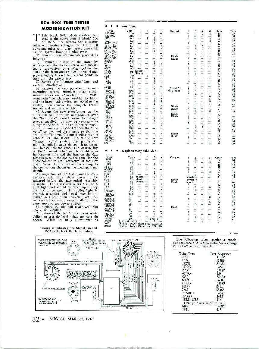
RCA 9901 TUBE TESTER
MODERNIZATION KIT
HE RCA 9901 Modernization Kit 1 enables the conversion of Model 156
or 156A tube testers for checking tubes with heater voltages from 1.1 to 120 volts and tubes with a miniature base such as the Hytron Bantam Junior types.
To convert these instruments proceed as follows :
1) Remove the case of the tester by withdrawing the bottom screw and insert- ing a screwdriver or similar tool in the slots at the front and rear of the panel and prying lightly at each of the four points in turn until the case is free.
2) Remove the "filament volts" knob and switch mounting nut.
3) Remove the two power -transformer mounting screws, unsolder those trans- former wires not connected to the "fila- ment volts" switch, also unsolder the black and the brown cable wires connected to the switch, then remove the complete trans- former and switch assembly.
4) Mount the new transformer on the other side of the transformer bracket, over the "line volts" control, using the longer screws supplied. It may be necessary to elongate the holes in the transformer brack- et, or remove the washer between the "line volts" control and the chassis so that the arm of the "line volts" control will clear the transformer laminations. Mount the new "filament volts" switch, placing the dial plate (supplied) under the switch mounting nut. Reassemble the knob. The locating lug on the "filament volts" switch should be in its locating hole and the line on the dial plate even with the one on the panel for the knob pointer to read correctly on the new dial. Wire the transformer according to the connections shown in the accompanying circuit.
An inspection of the tester and the con- nections will show those wires to be soldered before the mechanical assembly is made. The red -green wires are for a pilot light and should be taped up if they are not to be used. If a pilot light is desired, a socket and jewel may be in- stalled in a hole /-in. diameter, with Ag- in counterbore 22 -in. deep, drilled in the panel next to the power switch.
5) Replace the old roll chart with the new chart supplied.
A feature of the RCA tube tester is its ability to test doubtful tubes for possible opens. While ordinarily a test such as
Rewired as indicated, the Model 156 and 156A will check the latest tubes.
FAR 51 E.LEAO ERrE DED INTO FAR SIDE.LEADS EXTENDED INTO TRANSFORMER ARE LOCATED ON NEAR SIDE
32 SERVICE, MARCH, 1940
new tubes Type Volts 1 2 3 4 Output 5 6 7 8 Class Type
EK 1000 12.6 1 - - - - 7 8 D 23 EK 1000 12.6 - 5 - - - D 29 1221 6.3 - 2 3 - - - 8 A 32 1223 6.3 - - 3 4 - - 8 A 32 6AE5 (G) 6.3 - - 3 - 5 - - - A 39 6SJ7 (G) 6.3 - - - 4 - 6 7 - A 36 6SK7
(G) 4 6 7 - A 34
6SF5 6.3 - - 3 5 - - - D 37 6SQ7 (G) 6.3 1 - 6 - - D 33 6SQ7 (G) 6.3 - - - 4 Diode 6SQ7 (G) 6.3 - Diode 5 - - - C 25AC5 25.0 - 3 - 5 - - - A 36 6SA7 6.3 1 - 3 4 5 - - - A 38 6SC7 6.3 1 - 3 - - - - D 28 6SC7 6.3 - - - 4 5 - - - D 28 4A6G 2.0 Shorts - 3 4 - - - - A 23 4A6G 5X3
2.0 Shorts 5.0 - - -
2 - - - 5 6 - - - - - - E A
23 24
5X3 5.0 - - 3 - 24 1G4G 1.5 - - 3 - 5 - 17 1G6G 1.5 - - 3 4 - - - - A 24 1G6G 1.5 - - - - 5 6 - - A 24 2A4G 2.5 - - 3 - 3 and 5 5 - - - A 38 12A8GT 12.6 - - - - May Short 5 6 - - A 33 12A8GT 12.6 - - 3 4 5 6 - 8 A 36 I2F5GT 12.6 - - - 4 - - - 8 A 38 12J7GT 12.6 - - 3 4 - - - 8 A 33 12K7GT 12.6 - - 3 4 - - - 8 A 32 12Q7GT 12.6 - - 3 - - - - 8 A 35 12Q7GT 12.6 - - - 4 Diode - - - - C 1207GT 12 8
12.6 - 12.6 - - - - 3
- - Diode 5
6 - 8 A 25 12C8 12.6 - - - 4 Diode - - - - C 12C8 12.6 - - - - Diode 5 - - - C 12SA7 12.6 1 - 3 4 5 - - - A 38 12SC7 12.6 1 - 3 - 28
5 - - - D 28 12SJ7 12.6 - - - 4 - 6 7 - A 36 12SK7 12.6 - - - 4 - 6 7 - A 34 12SQ7 12.6 1 - - - - 6 - - D 33 12SQ7 12.6 - - - 4 Diode - - - - C 12SQ7 12.6 - - - - Diode 5 - - - C 35Z4GT 30 - - - 5 - - - A 40 35L6GT 30 - - 3 4 5 - - - A 38 879 2.5 - - - - - - - 8 H 10
supplementary tube data
Type 1B7G
Volts 1
1.5 - 2 3 - - 4 - Output 5 6 5 6
7 - 8 - Class A
Type 23
1B7G 1.5 - - - 4 5 6 - 8 A 25 1Q5G 2Y2 6AD5G 6R6G
1.5 - 2.5 - 6.3 - 6.3 -
- 3 - - - 3 - 3
4 - - 5 - 5 - 5 -
- - -
- 8
8
B
A A
19 20 34 29
7B5 7B6 7B6
6.3 6.3 shorts 6.3 shorts
- 3 - 3 - - 4 4 - Diode
6 shorts- shorts 6
- - - - - -
A A C
32 35
7B6 6.3 shorts - - - Diode shorts- - 8 C 7B8 7B8
6.3 - 6.3
- - - 3 4 4
5 - 5 6
- - - 8
A A
32 35
7C5 12B8GT
6.3 - 12.6 1
- 3 - - 4 - 6 5 - - - - - A
A 35 37
12B8GT 12.6 - - 3 4 - - - 8 A 35 25B8GT 25B8GT
25 - 25 1
- 3 - - 4 - 5 - - 8 A
34 38
25D8GT 25D8GT 25D8GT 25X6GT 2SX6GT
25- - 25 - 25 1
25 - 25 -
- 3 - - - - - 3 - - 4 - - - -
Diode 5 6
_ 5 -
- - -
8 - _ -
A A CA
A
35 35
36 36
32L7GT 32L7GT
30 - 30 - - 3 - - 4 - 5 - 6
- - - - A A
39 39
35Z5GT 320R4
30 - (Ballast tube) 1
- shorts - 3 - 5 - - -
7 - - A
I 41
200R (Ballast tube) (Same as KX55A) 200R4 (Ballast tube) (Same as KX55B)
The following tubes require a special test sequence and in two instances a change in "Class" selector switch.
Tube Type 1A6 106 1C7G 1D7G 2A7 6P7G 6A7 6A8G 6D8G 6SA7 7A8 12A8GT 12SA7 1852, 1853 Change class
6K8 1851
Test Sequence 45382 45382 54683 54683 53482 438 53482 54683 54683 5413 58463 54683 5413 416
selector to L 4385
438
www.americanradiohistory.com
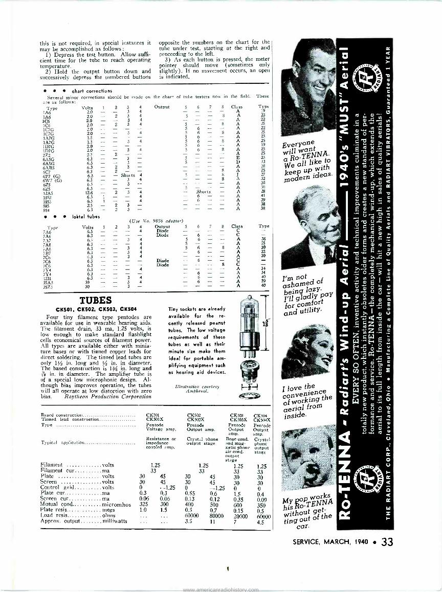
this is not required, in special instances it may be accomplished as follows :
1) Depress the test button. Allow suffi- cient time for the tube to reach operating temperature.
2) Hold the output button down and successively depress the numbered buttons
opposite the numbers on the chart for the tube under test, starting at the right and proceeding lo the left.
3) As each button is pressed, the meter pointer should move (sometimes only slightly). Ii no movement occurs, an open is indicated.
chart corrections Several minor corrections should be made on
are as follows: Type Volts 1 2 3 4
1A6 2.0 - - 3 4
1A6 2.0 - 2 3 4 106 2.0 - - 3 4
106 2.0 - 2 3 4
1C7G 2.0 - - - - 2.0 - - 3 4
1A7G 1.5 - - - - 1A7G 1.5 - - 3 4
1D7G 2.0 - - - - 1D7G 2.0 - - 3 4
2Z2 2.5 - 2 - - 6A5G 6.3 - - 3 - 6AB5 6.3 - 2 3 - 6C7 6.3 - 2 6P7 (G) 6.3 - - Shor- ts 4
6W7 (G) 6.3 - - 3 4 6Z5 6.3 - - 3 - 6Z5 6.3 - - - - 12A5 12.6 - 2 3 4
1852 6.3 1 - - 4 1853 6.3 1 - - 4
885 2.5 - 2 3 - 884 6.3 - 2 3 -
loktal tubes
Type 7A6 7M 7A7 7A8 'A8 7B7 7C6 7C6 7C6 7Y4 7Y4 1231 35A5 35Z3
Volts 6.3 6.3 6.3 6.3 6.3 6.3 6.3 6.3 6.3 6.3 6.3 6.3
30
( Use No.
the chart of tube testers now in the field. These
Output 5
5
9858 adaptor)
5 5
5
5 5
5
5
5 5
5
5
1 2 3 4 Output 5 - - - 4 Diode - - - - Diode - - 3 - 4 5 - - - 4 5 - - 3 4 5 - 3 4 - - 3 4
- - - - - 4
- 3 4 3 4
30 - 3 -
Diode Diode
6 7
6 - 6 - 6 - 6 - 6 - 6
Shorts. 6 - 6 -
8 Class Type - A 19 8 A 23
A 22 8
A 25 - A 22
8 A 25 A 23
8 A 25 - A 19 8 A 23
A 25 - E 33 - D 33 A 28
8 A 25 J 27
8 A 32 - A 30 - A 30 - A 28 - A 41 - A 39 - A 38 - A 38
6 7 8
6 - - 6
6 - 8 - 6 - - - 6 - - - - - - - 8
- 6 - - - 6 - - 6 _ -
Class C C A 36 A 23 A 30 A 32 A 30 C - C - A 34 A 34 A 40 A 39 A 40
Type
TUBES CK501, CK502, CK503, CK504
Four tiny filament type pentodes are available for use in wearable hearing aids. The filament drain, 33 ma, 125 volts, is low enough to make standard flashlight cells economical sources of filament power. All types are available either with minia- ture bases or with tinned copper leads for direct soldering. The tinned lead tubes are only 1% in. long and % in. in diameter. The based construction is les in. long and Tes in. in diameter. The amplifier tube is of a special low microphonic design. Al- though bias improves operation, the tubes will all operate at low distortion with zero bias. Raytheon Production Corporation
Tiny sockets are already
available for the re-
cently released peanut tubes. The low voltage requirements of these
tubes as well as their minute s'ze make them ideal for portable am-
plifying equipment such as hearing aid devices.
Illustration courtesy Arnphenol.
Based construction CK501 CK502 Tinned lead construction CK501X CK502X Type Pentode Pentode
Voltage amp. Output amp.
Resistance or Crystal phone Typical application impedance output stage
coupled amp.
CR503 CK504 CK503X CK504X
Pentode Pentode Output Output amp. amp.
Bone cond. Crystal and mag- phone netic phone output air cond. stage output stage
Filament volts 1.25 1.25 1.25 Filament cur ma 33 33 33 Plate ..volts 30 45 30 45 30 Screen volts 30 45 30 45 30 Control grid volts 0 -1.25 0 -1.25 0 Plate cur ma 0.3 0.3 0.55 0.6 1.5 Screen cur ma 0.06 0.06 0.13 0.12 0.35 Mutual cond micromhos 325 300 400 500 600 Plate resis. megs 1.0 1.5 0.5 0.7 Load resis. ohms ... ... 60000 80000
0.1 2055 00
Approx. output milliwatts 3.5 11 7
1.25 33 30 30 0 0.4 0.09 350 0.5 60000 4.5
Everyone wilol TENNA. a R
e 3lewdallnwt moe ideas.
asháméd of being lazy I'll gladlYY PaY
for c
fort and utility.
I love the convenienCe of working the aerial from inside.
MY oP works hiso-TENNA without of
ethe tíng car.
ro w (I)
G al ...
w rn
r,b N
-d ái
U .c7 - rN-. ry
N
w ; G
á U
ro
7:1 .7J o G G
G ro ro X en X, U U w r.
E "'' G . ro,b ÿ o°l3 l b ál V r0
O U
+ - >+b G
Z GWG W HE . w
O 3ogi s (1)
-Ó L>~ o W al, w
.1) id.)
G O
ro
E ro
0 o >+ s.
N ro
U
w
ro f
t
rd
a>
SERVICE, MARCH, 1940 33
1
www.americanradiohistory.com

PHONOGRAPH NEEDLE
Permo Products Corp., 6415 Ravenswood Ave., Chicago, have developed a special phonograph needle tipped with an alloy made from the rhodium, ruthenium and osmium group. The inherent characteris- tics of the alloy provide self-lubricating effect which reduces record wear, it is said. The needle is designed to give approximate- ly 50 -hours service on standard 10 -in com- mercial shellac records.
MALLORY FILTER
A new audio or hum filter unit, the Mal- lory VF -223, is now available for use with all single unit Mallory Vibrapacks. The filter condenser is a three -section Mallory FPT-390 of 15-15-10-mfd capacity, 450
working volts. The two 15-mfd sections are used with the choke to form a con- ventional pi -section filter, while the 10-mfd section connects to a separate terminal so that, if desired, a filtered intermediate out- put voltage may be obtained. The filter choke is rated at 100 ma and has a d -c resistance of 90 ohms. P. R. Mallory & Co., Inc., Indianapolis, Ind.
SOLDERING IRON TIPS
Stanley Tools, New Britain, Conn., have announced a new line of Armor Clad solder- ing iron tips for their screw tip and plug tip electric soldering irons. The Armor Clad tip is a copper tip covered with a spe- cial metal coating which it is said protects the high conductivity copper core.
Additional information may be obtained directly from Stanley Tools at the above address.
OPERADIO INTERCOM SYSTEM
Operadio Manufacturing Co., St. Charles, Ill., have announced their Model BH com- bination paging and intercommunication system. The standard master station with ten push -buttons, one for each outlying speaker in the system, may, by means of additional switches, provide paging and re- turn speech for an unlimited number of stations. The addition of a call switch per- mits the speaker stations to call the master station.
Additional information directly from Operadio.
may be obtained
34 SERVICE, MARCH, 1940
HYTRON DISPLAY CABINET
Hytron offers a display cabinet free with the purchase of a standard assortment of 50 Bantam GT type tubes. The cabinet will
run
IQP (HOSE WHO WANT THE BM
liai 11111
0RI611WOR OF THE BANTAM /a a.
ii II i
ASK FOR ROOM (USES
house 50 GT types and can easily be de- tached from the wall so that it may be carried out on the job. Additional in- formation may be obtained directly from Hytron Corp., 76 Lafayette St., Salem, Mass.
RADIO CITY MULTIMETER
Radio City Products Co., Inc., 88 Park Pl., New York City, have announced their Model 411 Supertester for a -c and d -c
measurements. The instrument features 5 a -c and 5 d -c voltage ranges up to 5,000 volts at 5,000 -ohms -per -volt on d -c. There are a total of 33 ranges for 8 functions. A 3 -in meter with a 200 -microampere movement is used.
TRIUMPH BATTERY TESTER
Triumph Model 632 Percent -O -Meter is an instrument designed to check individual A and B batteries and battery packs under
load conditions. A 3 -in. meter scale, cali- brated in percent of new battery voltage showing "Replace -Useful -New" areas, is used. Rotary switch selects 11 ranges from 1% volts, full scale, to 135 volts, full scale. Additional information can be obtained from Triumph Mfg. Co., 4017 W. Lake St., Chicago.
ICA UNI -MOUNT ANTENNA
The ICA 1940 Uni -mount underhood auto -radio antenna has a dual bracket; static discharge ball tip ; is made of ad- miralty brass, triple chrome plated and comes with both underhood and alligator mounting brackets. Additional information on this and other ICA products may be obtained directly from Insuline Corp. of America, 30-30 Northern Blvd., Long Is- land City, N. Y.
ATLAS SPEAKERS
Atlas Sound Corp., 1449 39 St., Brook- lyn, N. Y., have announced a new line of storm -proof dynamic reflex trumpets and driver units. The model illustrated has a 6 -foot air column, bell opening of 29 in and total depth of 31 in. The line includes
trumpets and units of various sizes. The p -m driver unit is completely enclosed.
METAL -CASED ELECTROLYTICS
A new BR series of tiny, tubular elec- trolytic capacitors has been announced by Cornell-Dubilier. Only about one -fifth the size and weight of the older "can" type electrolytics for equivalent capacity and voltage ratings, these new units are avail- able in a wide variety of capacity and volt- age ratings-from 4 to 40 mfd, 25 to 500 volts, working. Each BR capacitor is her- metically sealed, inclosed within an alumi- num container over which is fitted a var- nished cardboard sleeve. Bare wire leads are riveted to rubber -capped bakelite ends.
Available in single and dual capacity ranges. Described in Catalogue No. 175A free on request from Cornell-Dubilier Elec- tric Corporation, South Plainfield, N. J.
ALLIED SPEECH MASTER
The Knight Model A12255 portable one - unit sound system features 14 -watts out- put, inverse feedback, separate microphone and phono pickup controls, bass -treble con- trol, speaker selector and provision for additional speakers. It is designed espe- cially as a portable system for lecturers, etc. Additional information may be ob- tained directly from Allied Radio Corp., 833 W. Jackson Blvd., Chicago.
www.americanradiohistory.com
ATR VIBRATORS
Write for FREE ATR
PROVEN UNITS of the
HIGHEST QUALITY Engineered to perfection, ATR Replacement Vibrators set high standards of performance and construction. Their greater life and reliability is made possible by new designs utilizing 3/16" diameter tungsten contacts with full wiping action. Other impor- tant features:
Perforated Reed of highest quality Swedish Spring Steel.
Highly Efficient Magnetic Cir- cuit with formed base,.
Mica and Metal Stack Spacers with Two -Bolt Stack construc- tion.
Extra Flexible Leads with Tinned Clamp Supports.
Highest Precision Construction and Workmanship.
1940 16 - PAGE VIBRATOR GUIDE The most comprehensive and complete in the industry, covering ATR replacement vibrators for practically all standard vibrator -operated receivers, including Automotive, Aviation, Police and Household Sets.
ATR vibrators, the heart of vibrator -operated power supplies, are proven units of the highest quality, engineered to perfection. They are backed by more than ten years of vibrator design and research, development and manufacturing - ATR pioneered in the vibrator field. American Television & Radio Co. has consistently devoted its efforts and energies to the perfection and production of vibrators and associated equipment, and today, after ten years of painstaking, persistent and diligent work resulting in steady development and progress, is considered the World's leader in its field. All ATR Products incorporate only the best materials and workmanship and are carefully manufactured under rigid engineering inspec- tions and teats, making them the finest that can be built. ATR VIBRATORS ARE FULLY GUARANTEED I YEAR. INSIST UPON ATR
AMERICAN TELEVISION & RADIO CO. ST. PAUL, MINN., U.S.A. Cable Address: "LIKEX." NEW YORK
A GOOD NAME
k1. GOES - t
il
he j' iÌ. ..o.
DEPENDABLE
It
LONG WAY The good name of Ken -Rad
Radio Tubes is due to the
high standards of their manu-
facture. KEN -RAD
CORPORATIONLAMP Owensboro. Kentucky
R A DI O TUBES C Sò
\
tite aesOLDED
SOLAR MFG. CORP.
Tubular Piper :apacitors ... molded in lard wax ... no moisture can cater .. much longer life ... buy zom our jobber in factory-se^led artons.
Write for Catalog
Bayonne, New Jersey
NOT IN PROFITABLE WORK BUT- 9WO1z4!
A common complaint of service- men are those sets that "take more time than they're worth." Unfortunately, the number of these sets is increasing so fast that more and more servicemen are becoming buried-not in profitable work but in worry. Worry because they cannot
charge enough to pay for their time.
There is only one solution- faster trouble shooting and fast- er repair work. There is only one way of accomplishing this- through increased knowledge. Begin today with these Rider Books.
SERVICING BY SIGNAL TRACING, By JOHN F. RIDER The Most Talked of Subject in the History of
Radio Servicing Use the system of servicing which is proved and endorsed-the system which is fastest-most modern-the system you can apply to all receivers regardless of age, type or make. Servicing by Signal Tracing operates independently of every limiting factor heretofore encountered. In this new book you learn how all receivers are brought to a common servicing level. Read this book and you will be able to service the most complicated set with greater speed and less effort. Over 360 pages-hard covers-only $2.00.
SERVICING SUPERHETERODYNES-Changes, changes, changes! That has been the history of the superheterodyne circuit. Make repairs quickly by analyzing the different parts of the circuit quickly. Rider shows you how. 288 pages. Profusely illustrated. Price $1.00.
CATHODE RAY TUBE
By JOHN F. RIDER This is the most complete and practical book ever written on the subject-the only one prepared especially for the radio service- man. New applications of the cathode ray tube during the past five years require that servicemen know its operation. 336 pages- over 450 illustrations-$2.50.
JOHN F. RIDER PUBLISHER, INC.
404 FOURTH AVENUE
NEW YORK CITY Export Div.: Rocke-Int. Elec. Corp. 100 Varick Street, New York City
Cable: ARLAB
Aeta THE OSCILLATOR
AT WORK BY John F. Rider
JUST OFF THE PRESS Get your money's This newobook tells all about Alt book
elt a e vilains the theory by m
Lions, ns
simple illustra - diagrams and curves. It gives you the facts you P ractical
theor need to combine your y and practice.
Get copy TODAY! 256
All
BANISH BEWILDERMENT - INCREASE PROFITS
aead RIDER BOOKS
SERVICE, MARCH, 1940 35
www.americanradiohistory.com
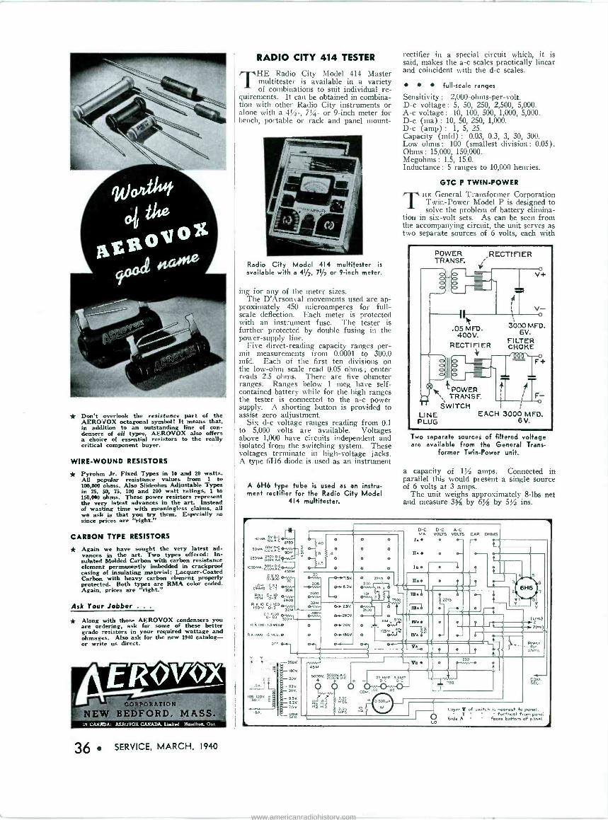
* Don't overlook the resistance part of the AEROVOX octagonal symbol! It means that, in addition to an outstanding line of con- densers of all types, AEROVOX also offers a choice of essential resistors to the really critical component buyer.
WIRE -WOUND RESISTORS
* Pyrohm Jr. Fixed Types in 10 and 20 watts. AU popular resistance values from 1 to 100,000 ohms. Also Slideohm Adjustable Types in 25, 50, 75, 100 and 200 watt ratings, 1 to 150,000 ohms. These power resistors represent the very latest advances in the art. Instead of wasting time with meaningless claims, all we ask is that you try them. Especially so since prices are "right."
CARBON TYPE RESISTORS
* Again we have sought the very latest ad- vances in the art. Two types offered: In- sulated Molded Carbon with carbon resistance element permanently imbedded in crackproof casing of insulating material; Lacquer -Coated Carbon with heavy carbon element properly protected. Both types are RMA color coded. Again, prices are "right."
Ask Your Jobber . . .
* Along with those AEROVOX condensers you are ordering, ask for some off these better grade resistors in your required wattage and ohmages. Also ask for the new 1940 catalog- or write us direct.
36 SERVICE, MARCH, 1940
RADIO CITY 414 TESTER
THE Radio City Model 414 Master multitester is available in a variety of combinations to suit individual re-
quirements. It can be obtained in combina- tion with other Radio City instruments or alone with a 4/-, 7%- or 9 -inch meter for bench, portable or rack and panel mount -
Radio City Model 414 multitester is available with a 41/2, 71/2 or 9 -inch meter.
ing for any of the meter sizes. The D'Arsonval movements used are ap-
proximately 450 microamperes for full- scale deflection. Each meter is protected with an instrument fuse. The tester is further protected by double fusing in the power -supply line.
Five direct -reading capacity ranges per- mit measurements from 0.0001 to 300.0 mfd. Each of the first ten divisions on the low -ohm scale read 0.05 ohms ; center reads 2.5 ohms. There are five ohmeter ranges. Ranges below 1 meg have self- contained battery while for the high ranges the tester is connected to the a -c power supply. A shorting button is provided to assist zero adjustment.
Six d -c voltage ranges reading from 0.1 to 5,000 volts are available. Voltages above 1,000 have circuits independent and isolated from the switching system. These voltages terminate in high -voltage jacks. A type 6H6 diode is used as an instrument
A 6H6 type tube is used as an instru- ment rectifier for the Radio City Model
414 multitester.
rectifier in a special circuit which, it is said, makes the a -c scales practically linear and coincident with the d -c scales.
full-scale ranges
Sensitivity : 2,000 -ohms -per -volt. D -c voltage: 5, 50, 250, 2,500, 5,000. A -c voltage: 10, 100, 500, 1,000, 5,000. D -c (ma) : 10, 50, 250, 1,000. D -c (amp) : 1, 5, 25. Capacity (mfd) : 0.03, 0.3, 3, 30, 300. Low ohms: 100 (smallest division: 0.05). Ohms : 15,000, 150,000. Megohms : 1.5, 15.0. Inductance : 5 ranges to 10,000 henries.
GTC P TWIN -POWER
THE General Transformer Corporation Twin -Power Model P is designed to solve the problem of battery elimina-
tion in six -volt sets. As can be seen from the accompanying circuit, the unit serves as two separate sources of 6 volts, each with
POWER TRANSF.
RECTIFIER
- V+
"
.05 MFD. 400V.
RECTIFIER y
R POWER \, TRANSF. SWITCH 1
LINE EACH 3000 MFD. PLUG 6 V.
3000 MFD. 6V.
FILTER CHOKE
Two separate sources of filtered voltage are available from the General Trans-
former Twin -Power unit.
a capacity of 1/ amps. Connected in parallel this would present a single source of 6 volts at 3 amps.
The unit weighs approximately 8 -lbs net and measure 3g, by 6jß by 5/ ins.
10 MA. SV
[II - 9, --Z
c s lov.
soMA.IOO2 C - 90M
250 MA. 2OSa..._ 1000MA. 5oovo{
IOOOVA{ 45pM
Ó 300
ONLoMwS O- Cx3l
R5MXI C}10 1 0J 2400
R X10 co+10 0.. 150M 0-3 32M Ci I000OMN
o-.OJ 300M' 1
R %too- I.sMEG.O
R%1000-15 MEG. 0
OEE o. 1
6.3v.
zz .5A
105-120V. Q 60-' a
2 40
1.5
.4
o
o
206 --oWN-
2400 0MA-
o
30oM
O
O 2250 O
255, 15
2500 0-t- O -m
D -c D -C A -C MA. VOLTS VOLTS CAP OHMS
IA -- IIA
Is
T500 e
mbl
t
4
6
2 2215
O!
Re
IVA
Y,
6H6
b
250V.
160V.
90V
23V. 20V
6.2V /50
"c:
AA.VV - 45M
500+V. Nevi
22 2. 2.
Mg ri2 KiE
G.
M.25 EG
ohms
ve 250
25 AMR 5AM. DD -c o -c /
0 500NA
M
'150 T COM. SEC.
Loyer If of switch is neo -est to ponel. I - furthest fron, panel. Side A - foses bottom of panel.
www.americanradiohistory.com
RECORDING DISCS
The Walco recording discs are now be- ing marketed by the Electrovox Company, 424 Madison Avenue, New York City. These discs have a special fibre -board base. The acetate coating, .008 inch thick, is said to be the same grade used on aluminum base records. In addition, the records are said to lie flat and have an indefinite shelf life. Records are now being produced in 6 in, 8 in, 10 in, and 12 in diameters. It is anticipated that 16 in discs will be avail- able shortly.
MONTGOMERY -WARD PROFESSIONAL P -A This unit has four individual mike chan-
nels, two phonograph inputs and separate bass and treble controls. The mike inputs use four input tubes and individual volume
controls. One master volume control is used for the two phonograph inputs and a second master control with provisions for remote operation is used to adjust the over- all volume of all channels. The individual bass and treble controls are of the booster type, permitting adjustment of bass or treble individually.
This preamplifier when attached to the chassis of the 60- or 100 -watt amplifiers be- comes an integral part of the amplifier. When more than 100 watts is wanted, extra 100 -watt chassis can be connected to the preamplifier. Provisions are made for using up to five 100 -watt chassis.
This equipment was developed by Mont- gomery Ward, Chicago, and will be de- scribed in their new sound catalog, ready about May 1.
OXFORD-TARTAK APPOINTMENT Paul H. Tartak, president of Oxford-
Tartak Radio Corp., has announced the ap- pointment of Bob Adams, sales engineer. Bob is well known in the industry, having been connected with it in various capacities for the past seventeen years.
CROWE BULLETIN
Crowe Name Plate & Mfg. Co., 3701 Ravenswood Ave., Chicago, have made available a bulletin covering their line of remote controls for automobile radios. Considerable information is contained in this 16 -page booklet. Write for Bulletin No. 232.
ERWOOD SLOGAN CONTEST Erwood Sound Equipment Co., 224 W.
Huron St., Chicago, are offering $450 worth of public-address equipment as prizes for the best slogan written around any feature of an Erwood Sound System. Contest closes May 15. For additional de- tails write to Erwood at the above address.
COMPARE POWER FACTOR!
It
cokbomoo47ce, ,
MFD , .
5.Q
NATIONAL UNION CONDENSERS IN ALL POPULAR TYPES FOR
REPLACEMENTS Compare Them
Feature for Feature! POWER FACTOR-The life and performance of electrolytic condensers are determined to a considerable extent by the power factor. Compare the low power factor of National Union condensers with other leading makes. HIGH BREAKDOWN VOLTAGE-Uniformly aged and tested considerably above their rated operating voltages. UNIFORMITY-Double checked to insure re- liability and uniformity of characteristics. CAPACITY-Very close tolerances result in extreme uniformity and freedom from replace. ment difficulties. LOW LEAKAGE-Remember, N. U.'s check- test of every condenser insures uniformly low leakage and good leakage recovery. Excessive leakage causes more service difficulty than any other type of condenser trouble. Just compare. SIZE-Type for type, National Union Con- densers are as small or smaller than leading competitive makes. Yet Priced the Same.
They're Built for the Service Business!
We have attempted to design a complete line of replacement condensers which would ade- quately meet the needs of the serviceman. Uniformity and excellent electrical character- istics result in freedom from "call-backs" and field difficulties. Smaller sizes and mechanical ruggedness result in quick and easy replace- ment installations. Complete assortment of condensers for re- placement applications now available. All popular types and sizes: Junior Box, Standard Box, Universal Replacement, Junior Can, Standard Can, Wets, Large Can, Ceramites, Wumites, Tubular Papers, Auto Generator, Auto Vibrator, Uncased Paper, Transmitting.
N. U. CONDENSERS MAY BE
APPLIED TO TUBE DEALS Send for Catalog
NATIONAL UNION RADIO CORPORATION NEWARK, N. J.
SERVICEMEN! YOUR METER! 34 RANGES 4g" METER Mirror backed scale. Knife -edged pointer. Volt -Ohm -Decibel. Output and Milliammeter
Complete with 15 -Volt Battery.
MODEL 333 MULTIRANGE METER. See it at your JOBBER or write to FACTORY for com- plete 1940 SERVICE- MAN'S instrument catalog.
TRIUMPH MFG. CO. 4017-19 W. LAKE ST. CHICAGO, ILL.
SERVICE, MARCH, 1940 37
www.americanradiohistory.com
ASSOCIATIONS (Continued from pane 30)
soon. We are looking forward to a most prosperous 1940.
John K. Gross, Secretary
sfeubenville Under the lead of the Steuben-
ville chapter, a great deal of pub- licity concerning local broadcast con- ditions in and around Steubenville was published in the local newspaper. Copies of the article are in great demand and have been made up for distribution to the trade.
Leonard Roberts, Secretary
westchesfer We elected the following officers
for 1940: Jack Livingstone, presi- dent; Philip Brigante, vice president; Arthur Hinkelbein, secretary, and Joseph Hanasik, treasurer.
We are cooperating, through our representative, Henry Lutters, in the regional setup in the NAB -RSA Service Plan.
Henry Lutters
JOBBER GROUP nrpda
HE following new members have been added to the rapidly grow- ing roster of the National Radio
Parts Distributers Association. A successful membership drive has been in progress for the past two months. A trip of approximately 5,000 miles covering the states of New York, Ohio, Indiana, Kentucky, Missouri, Nebraska, Iowa, Minnesota and Wis- consin, has been completed and a number of additional members have joined during this period. The names of these are: in New York, Radio Equipment Corp., Buffalo; Roy C. Stage, Syracuse; W. E. Berndt, Sy- racuse; Stewart W. Smith, Syracuse; Federal Radio Supply Co., Bing- hamton; Fred C. Harrison, Elmira; Ft. Orange Radio Distributing Co., Albany; Edwin E. Taylor, Albany;
and Vaeth Electric Co., Utica; in Ohio, Ross Radio Co., Youngstown; Radio Repair & Service Co., Akron; Armstrong Radio Co., Canton; Thompson Radio Supplies, Colum- bus; Bell Radio Parts Co., Colum- bus; Lima Radio Parts Co., Lima; United Radio, Inc., Cincinnati; and Radio Supply Co., Cincinnati; in Indiana, Van Sickle Radio Supply Co., Indianapolis; and Archer & Evinger, Terre Haute; in Missouri, Ebinger Radio & Supply Co., St. Louis; Tom Brown Radio Co., St. Louis; and Manhattan Corp., Kansas City; in Iowa, Dukes Radio Co., Sioux City; Wholesale Radio Lab- oratories, Council Bluffs; and Iowa Radio Des Moines; in Neb- raska, H.
Corp.,. Noll Co., Omaha; in
Kentucky, P. I. Burks Co., Louis- ville; in Illinois, Lurtz Electric Co., Belleville; in Pennsylvania, Jordon Radio Co., Erie; in Washington, Seattle Radio Supply Co Inc., Seat- tle; in Oregon, United Radio Supply, Inc., Portland in Connecticut, Stam- ford Radio Supply, Stamford; in Wisconsin, Marsh Radio Supply Co., Milwaukee, Radio Parts Co., Inc., Milwaukee; Valley Radio Distribu- tors, Appleton; and Appleton Radio Supply Co. Appleton; in Minnesota, Northwest Radio, Duluth; Lew Bonn Co., Minneapolis; Hall Electric Co., St. Paul; and Radio Maintenance Co., Minneapolis.
Art Moss. Executive Secy.
california Doctor Lester Reukema gave a
supplementary talk on the actual progress and public acceptance of television, as he found it in the East, at 1608 Webster Ave., Oakland, Feb. 26. The meeting was attended by members who took Dr. Reukema's Television course last spring. The lecture was accompanied by colored pictures, taken by Dr. Reukema dur- ing the course of his trip, which covered several thousand miles.
William Appleton, Secy.
canada Through the courtesy of Vancouver
Radio Engineers, the Vancouver section of the Associated Radio Technicians of B. C. was given an interesting techncial lecture on Feb. 28, by Bill Cooms of Portland, Ore- gon. The subject was "Design and Uses of Various Pieces of Test Equipment.
evansville Our secretary, Kearnie Smith de-
livered a concise talk together with a demonstration on the signal tracer. Julius Groeninger, past president, supplemented the talk with applica- tions for the vacuum -tube voltmeter and visual and radio tracing.
A new plan for membership cam- paign has been inaugurated by V n C. Norwood, president, an H. U. C. Naval radio graduate, incorporating ideas borrowed from the battleship.
Van C. Norwood, President
OTHER GROUPS
Iouisville CHARLES R. WEXLER, head of
the circuit laboratories for the Ken -Rad Tube & Lamp Corp.,
of Owensboro, Ky., was guest speaker at the Louisville Service Men's meeting held at the Brown Hotel, Louisville, Ky., Feb. 6.
Mr. Wexler spoke on "Trends in 1940 Radio Receiver Design." He gave an understandable, down-to- earth picture of the development of 1940 receivers, and the engineering and service problems encountered. Mr. Wexler's talk was enthusiasti- cally received by the forty-five Ser- vice Men present, and he was in- vited to return at a later date.
new york
A new New York Service Men's organization has been formed under the title: "Independent Radio Service Men's Association of New York City," and has its offices at 225 Broadway, New York.
Typical of the aims of the associa- tion, according to Sigmund C. Fried- man, its executive secretary, is its clearing house; its exchange for job estimates protection; the licensing and guaranteeing of its members; financial and merchandising guid-
Sigmund C. Friedman
ance; group insurance; a legal ser- vice bureau, to mention a few.
It aims not to interfere or overlap any existing organization in the radio service field, but rather to supplement and complement these societies.
ohio New Tubes and their applications
warrants special and continued study on the part of today's aggres- sive radio Service Men, declared Walter Jones, Hygrade Sylvania commercial engineer, before meet- ings of Service Men in Toledo and Cincinnati, Ohio.
Mr. Jones conducted successful, well attended meetings in these two big towns last week. They were sponsored by Toledo and Cincinnati tube jobbers who assisted Mr. Jones in the arrangements and conduct of the meetings.
Henry C. L. Johnson
r. Serviceman:
R.S.A. PUTS YOU ON THE AIR! Listen In!, Broadcasters are cooperating with R.S.A. to sell radio
servicing to the American Public! Radio Listeners everywhere are learn- ing that it pays to call an R.S.A. man! It means increased business and more money for R.S.A. members!
And-this is only one of the big advantages of the R.S.A. Program! Year -Round Sales -Promotion to build Public Confidence, Technical Help for Members, Bulletins, and many other important business -aids are regu- lar features in the R.S.A. program! Cash in on growing Public Acceptance of R.S.A.-Join Today!
Let's Grow Together in 1940!
RADIO SERVICEMEN
OF AMERICA, Inc. JOE MARTY, JR., EXECUTIVE SECRETARY
304 S. DEARBORN STREET, CHICAGO, U.S.A.
38 SERVICE, MARCH, 1940
fBIEB MAIL
RADIO SERVICEMEN OF AMERICA, INC. 304 S. Dearborn St., Chicago, III.
u Address
City State I am interested in R.S.A. Membership. Tell me about it I am enclosing $4.00 for National dues and initiation. Covers dues up to Jan. 1, 1941, in accordance with special dues concession
(Does not include Local Chapter dues where Local Chapters are organized.) S-340 á iwmiBdl
THIS COUPON NOW!.B. Name
www.americanradiohistory.com

._.
:;:'aa%: y`v :`. .._.:.ti .... rti ktr :. c /:;
..,; PERMO POINT GIVES YOU A NEEDLE FOR EVERY
PHONOGRAPH NEED! FOR RECORDING- a new stylus equalling cutting ability of sapphire on nitrate coated blanks. Cuts clean
grooves, free from surface noises. Records entire frequency range. Minimum loss of high frequencies-no
"peaks". Permo Metal point gives long life. MICROSPECTED for uniformity, packed in special protective
metal container.
FOR TRANSCRIPTION- the Transcrip-tone gives an even response over entire audio frequency range- constant at over 10,000 cycles. Specially designed to transmit all frequencies useful in modern broadcasting
and recording work. Fits standard groove. Valuable in play-back and dubbing work. Permo Metal tip gives
35.50 hours service. Won't wear acetate, nitrate coated, commercial records-prolongs life with self-lubricating
Permo Metal point.
FOR REPRODUCTION- the Fidelitone for home record players and changers. Keeps surface noise at a
minimum. Permo Metal point assures finest full range reproduction. Record wear negligible with self-
lubricating action of Permo Metal. Up to 50 hours service on standard recordings. Long play for use in
home, salon, sound distributing systems, schools, etc.
TO INSURE PERFECT PERFORMANCE Every Permo Point Needle sold subjected to rigid Permo MICROSPECTION process
before it leaves the Permo laboratories. This process is a positive check on the precious Permo Metal point for perfect uniformity and performance. The above and other Perms Point Needles for professional and home use are available et all leading suppliers.
PERMO PRODUCTS Corporation POINT Manufacturing Metallurgists 6415 Ravenswood Ave., Chicago, Illinois
Gentlemen: Please send me your free booklet on Needles and
Records, and full information on Permo Point Needles.
Name
Address
REGAL TOKFONE UNITS
Regal Amplifier Mfg. Corp., 14 W. 17 St., New York City, have developed a new line of Tokfone intercommunication sys- tems, Series 600 which provide 2 -way com- munication between any master and any one up to ten remote stations. As many
as five independent conversations can be made simultaneously without crosstalk, it is said.
Additional information can be obtained directly from Regal.
FM RECEIVERS
Rapidly growing public interest in fre- uency modulation has opened up a new field for manufacturers of receiving sets. Freuency-modulation receivers capable of reproducing the programs sent out over the new type stations are now on the mar- ket. Stromberg -Carlson, General Electric and Radio Engineering Laboratories offer f -m receivers to the public in various con- sole and table models. The experimenter who wishes to build his own may secure a kit of all necessary parts with complete,
simple direction for assembling from Browning or Meissner. Other companies which have secured permission from Major Edwin H. Armstrong to manufacture sets under his patents are Zenith, Stewart - Warner, Pilot, Scott, National, Hammar- lund and Hallicrafters.
CLARION SOUND SYSTEM
The Clarion Model C443 24 -watt port- able sound system offers multiple inputs, push-pull 6L6G beam -power output, inverse feedback, 120 -db overall gain and a uni- versal output transformer with taps of 2, 4, 8, 16, 250 and 500 ohms. The fre- quency response is from 40 to 9,500 cps, it is said.
Additional information may be obtained directly from the Transformer Corp. of America, 69 Wooster St., New York City.
N. U. BATTERIES
National Union Radio Corp., 57 State St., Newark, N. J., is offering a complete line of batteries and battery packs for port- able receivers. The various sizes in the line are shown in the accompanying chart. Ad- ditional information may be obtained di- rectly from National Union.
KENYON TRANSFORMER
Kenyon Transformer Co., Inc., 840 Barry St., New York City, announce a new trans- former in their T line. The new unit, T223, has two 6.3 -volt windings, at two and three amp., respectively, and a 200 -ma secondary at 1,200 volts, center tapped. Additional information oat this and other Kenyon transformer items may be obtained directly from Kenyon at the above address.
¡-,
A "LA" to --
your pocket fl y -
factak
MODEL
739
$9.90
A.C.-D.C.
VOLT-OHM-MILLIAMMETER Pocket Volt - Ohm - Milliammeter with Selector Switch. Molded Case. . . . Precision 3 -Inch Meter with 2 Genuine Sapphire Jewel Bearings. AC and DC Volts 0-15-150-750-1500; DC MA. 0-1.5-15-150: High and Low Ohms Scales. . . .
Dealer Net Price, including all accessories, $9.90
WRITE FOR CATALOG
SECTION 317 COLLEGE AVENUE
READRITE METER WORKS, Bluffton, Ohio
SERVICE, MARCH, 1940 39
www.americanradiohistory.com
Volume Controls - Fixed Resistors
Ceramic Capacitors - Wave Band Switches
Division of Globe Union, Inc.
Milwaukee, Wisc.
CENTRALAB Stays Awake
The C. Q.'s have died down . too tired to Q. S. L. .
but Old Man CENTRALAB never bats an eye. Day in and day out this old owl is "wising up" to new develop- ments in the business. In ham shacks . . . on service benches . . . and in the laboratories . the word "CENTRALAB" continues to stand for dependability .. quality . . . and perform- ance.
Day or night . . . play safe with Centralab !
Here is a "customer acceptance" tube tester that is impressive in appearance, and in the quick "readings" it gives with its fine, busi- ness -like 7 -inch meter. A quick spin of the illuminated Roll-Dex Speed Chart will give you the settings in a flash. Entire chart scanned in less than 10 seconds. Has all tube sockets including Loctals, Bantam Jr., and the new 1.4 -volt Miniatures. Tests High Voltage series including 117Z6G; also Gaseous Rectifiers and Ballast tubes. Future tubes provided for by filament voltages in 20 steps from 1.1 to 117 volts. Has Neon Shorts test; Noise test jack, and separate line voltage control meter. Suede finish Silver Grey and Maroon case and panel of heavy, streamlined steel. Dealer Net Price $29.84
STANDARDIZE
SALES SERVICE
with
a Fi)LET
MODEL 1612 Counter Type Tube Tester
$29.84 Dealer Net
HAS RED DOT LIFETIME
GUARANTEED Write for Catalog-Section 173, Harmon Drive INSTRUMENT
THE TRIPLETT ELECTRICAL INSTRUMENT COMPANY Blutflom, Ohio
40 SERVICE, MARCH, 1940
POCKET SIZE VOLT. OHM -M IL LIAM N ETER
A complete pocket -else Volt- Ohm-Mnliammeter with AC - DC Voltage rangea; 0-10- 50-250-500-1000 at 1000 ohms per volt; DC Milliam- Peres 0-1-10-50-250 Low Ohms, % to 300; High ohm to 250,000 with provision, for higher reading, by ex- ternal batteries. Molded case and panel. Model 666...... Dealer Net Price
414.00
SHOPPING FOR AMPLIFIERS
WHEN shopping for an amplifier, you should give more weight to your own experience, and also to the
reliability of the manufacturer, than to the printed ratings. A careful inspection of the amplifier itself can, however, often reveal its true characteristics.
Some manufacturers obtain more than the rated output from an amplifier by rais- ing the tube voltages beyond those recom- mended as the maximum by the tube manufacturers. Tubes working under these conditions will actually deliver more than their rated output but their life will be seriously shortened. Tube failures are quite annoying and amplifiers working at an overload should be avoided.
The price of amplifiers is sometimes re- duced by using poor, undersized transform- ers. Skimpy transformers do not supply a steady voltage to the tubes and run ex- cessively hot. Poor voltage regulation in an amplifier causes distortion and failure to supply the extra power required when loud passages of music or speech are handled. Such an amplifier cannot repro - duct. the full brilliance of music or the in- flections of speech.
When poor output transformers are used there will be a loss of power transfer to the speaker and an uneven transfer of dif- ferent frequencies. This may not show up in the ratings of the amplifier because some manufacturers make their power output measurements at the output tube plates and not. at the secondary of the output trans- former.
There is usually a small amount of hum or buzz in the output of an amplifier. This should be so low as not to be noticeable in the output of the system. If large ampli- fiers are operated in a small room at low volume this hum may become quite promi- nent. When such an amplifier is used in a large auditorium or hall, of course, the hum would be barely noticeable.
If it is ever necessary to use a large amplifier where only a few watts are re- quired, and the hum is excessive, it can be reduced by using resistance loads to take the place of most of the output load. The resistance should, of course, be equal to the impedance of the speakers which it replaces. The power from the amplifier, including the hum, is then divided between the re- sistance and the speaker.
D. L. Elam and B. E. Philippsen MONTGOMERY WARD & COMPANY
PLUG-IN RESISTOR MANUAL
The Clarostat Plug -In Resistor Tube Service Manual contains 32 pages of plug- in resistor listings ; arranged by respective sets and resistor type numbers, and again as a numerical listing of all types with corresponding Clarostat standard and Claro - stat universal types, and other essential data such as number of 6.3 and 25-v tubes, total voltage drop, number of pilot shunts, current in ma, number of pilot lamps and type numbers of same, wiring code, base wiring, type of base, and base -wiring pin numbers. Copy of manual may be had by sending 15c in coin or stamps to Claro - stat Mfg. Co., Inc., 285-7 N. 6 St., Brook- lyn, N. Y.
ATR VIBRATOR GUIDE
American Television & Radio Co., St. Paul, Minn., have announced their 16 - page farm- and auto -radio vibrator re- placement guide. Copies of the guide may be obtained directly from ATR.
www.americanradiohistory.com
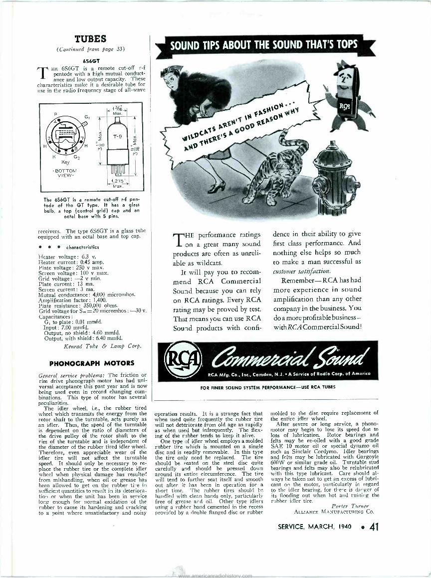
TUBES (Continued from page 33)
6S6GT THE 6S6GT is a remote cut-off r -f
pentode with a high mutual conduct- ance and low output capacity. These
characteristics make it a desirable tube for use in the radio frequency stage of all -wave
The 6S6GT is a remote cut-off r -f pen- tode of the GT type. It has a glass bulb, a top (control grid) cap and an
octal base with 5 pins.
receivers. The type 6S6GT is a glass tube equipped with an octal base and top cap.
characteristics
Heater voltage : 6.3 v. Heater current : 0.45 amp. Plate voltage: 250 v max. Screen voltage : 100 v max. Grid voltage: -2 v min. Plate current: 13 ma. Screen current: 3 ma. Mutual conductance : 4,000 micromhos. Amplification factor : 1,400. Plate resistance: 350,000 ohms. Grid voltage for S. = 20 micromhos : -30 v. Capacitances :
G, to plate : 0.01 mmfd. Input : 7.00 mmfd. Output, no shield: 4.60 mmfd. Output, with shield : 6.40 mmfd.
Kenrad Tube & Lamp Corp.
PHONOGRAPH MOTORS
General service problems: The friction or rim drive phonograph motor has had uni- versal acceptance this past year and is now being used even in record changing com- binations. This type of motor has several peculiarities.
The idler wheel, i.e., the rubber tired wheel which transmits the energy from the rotor shaft to the turntable, acts purely as an idler. Thus, the speed of the turntable is dependent on the ratio of diameters of the drive pulley of the rotor shaft to the rim of the turntable and is independent of the diameter of the rubber tired idler wheel. Therefore, even appreciable wear of the idler tire will not affect the turntable speed. It should only be necessary to re- place the rubber tire or the complete idler wheel when physical damage has resulted from mishandling, when oil or grease has been allowed to get on the rubber tire in sufficient quantities to result in its deteriora- tion or when the unit has been in service long enough for normal oxidation of the rubber to cause its hardening and cracking to a point where unsatisfactory and noisy
SOUND TIPS ABOUT THE SOUND THAT'S TOPS
THE performance ratings on a great many sound
products are often as unreli-
able as wildcats. It will pay you to recom-
mend RCA Commercial Sound because you can rely
on RCA ratings. Every RCA rating may be proved by test.
That means you can use RCA Sound products with confi-
dence in their ability to give first class performance. And nothing else helps so much
to make a man successful as
customer satisfaction.
Remember-RCA has had more experience in sound amplification than any other company in the business. You do a more profitable business- with RCA Commercial Sound !
äw#aadfisd RCA Mfg. Co., Inc., Camden, N.J. A Service of Radio Corp. of America
FOR FINER SOUND SYSTEM PERFORMANCE-USE RCA TUBES
operation results. It is a strange fact that when used quite frequently the rubber tire will not deteriorate from old age as rapidly as when used but infrequently. The flex- ing of the rubber tends to keep it alive.
One type of idler wheel employs a molded rubber tire which is mounted on a single disc and is readily removable. In this type the tire only need be replaced. The tire should be seated on the steel disc quite carefully and should be pressed down around its entire circumference. The tire will tend to further seat itself and smooth out after it has been in operation for a short time. The rubber tires should be handled with clean hands only, particularly free of grease and oil. Other type idlers using a rubber band cemented in the recess provided by a double flanged disc or rubber
molded to the disc require replacement of the entire idler wheel.
After severe or long service, a phono - motor may begin to lose its speed due to loss of lubrication. Rotor bearings and felts may be re -oiled with a good grade SAE 10 motor oil or special dynamo oil such as Sinclair Cordymo. Idler bearings and felts may be lubricated with Gargoyle 600W or similar grade oil. Turntable stud bearings and felts may also be relubricated with this type lubricant. Care should al- ways be taken not to get an excess of lubri- cant on the motor, particularly in regard to the idler bearing, for there is danger of its flooding out when hot and ruining the rubber idler tire.
Porter Turner ALLIANCE MANUFACTURING CO.
SERVICE, MARCH, 1940 41
www.americanradiohistory.com
OHMOTE ;
RESISTORS , Do a Better .job!
_ _ _ _ _ _ _ _ You're sure of dependability and exact performance, Mr. Serviceman, when you install Ohmite vitreous -enameled wire -wound resistors. Ask your Jobber today for these and other Ohmite Parts.
Ohmite Fixed Resistors The same Ohmite vitreous -enameled resistors used everywhere by promi- nent designers and manufacturers. Wide range of stock sizes from 25 to 200 watts, in many resistance values.
-1
L_S,
Ohmite "Dividohms" Keep 'em handy for quick replacement or change of resistance value. Easily adjusted to exact resistance-or tapped where needed. Ideal voltage dividers. Ratings from 10 to 200 watts; resis- tances up to 100,000 ohms.
SEND COUPON TODAY - - -I 1 OHMITE MANUFACTURING CO. I
4878 Flournoy Street, Chicago, U. S. A.
I ! SEND ME FREE CATALOG 17
Name
Address
City State
©ll=llMllTIE RHEOSTATS RESISTORS TAP SWITCHES
WHEN YOU CHANCE YOUR ADDRESS
Be sure to notify the Subscription Department of SERVICE at 19 E.
Forty-seventh St., New York City, giv- ing the old as well es +he new address,
and do this at least four weeks in
advance. The Post Office Department does not forward magazines unless you pay additional postage, and we cannot duplicate copies mailed to +he old address. We ask your cooperation.
42 SERVICE, MARCH, 1940
RADIART COWL AERIAL
Radiart's 1940 side cowl aerial incor- porates an insulator which can be tight- ened anywhere along the aerial without tools, an advantage which permits easy one-man installation. The lead-in is of
NO TOOLS Fingers tighten in.ulator along rod
VIBRATION PROOF
H. kythr.ad.ar.
metal -to -metal
NO SHORTS All metal -to -me al thru th b dy I
the plug-in type and can be inserted after the aerial is completely installed. This also simplifies installation, it is said.
Additional information may be obtained directly from Radiart Corp., Cleveland, Ohio.
SOLAR RED -CAP ELECTROLYTICS
Solar's new Red -Cap electrolytics are sealed in metal tubes and, it is said, are rated to withstand extreme surges. They are designed as replacements for older standard types of paper condensers in the filter blocks of receivers. The units are all of the same length but diameters vary
with the capacity rating. This makes it easier to strap several units together to fit the space taken by the original filter.
Additional information on this and other Solar items may be obtained directly from Solar Mfg. Corp., Bayonne, N. J.
N. U. SOUND TUBES
National Union Radio Corp., 57 State St., Newark, N. J., have announced that they are prepared to supply a special line of tubes for use in sound amplifiers.
The tubes are branded Sound X/tra on the base to identify them. They can be substituted in all cases for the same types in the regular line. The emission limits are very high; gas and grid currents are held to low limits and every tube is carefully tested for hum and microphonics, it is said. In some cases changes have been made in construction.
PARMETAL CHASSIS
Parmetal Products Corp., 3262 49 St, Long Island City, N. Y., announce a line of
deluxe sloping front foundation units for public-address amplifiers. The chassis are finished in slate grey oven -baked crinkle enamel trimmed with red -striped chrome mouldings and handles. Additional in- formation may be obtained directly from Parmetal.
Crystal Microphone A public address favorite that also fills a long standing demand for a really good low priced microphone for universal use. Wide range (JT-30) and voice range (JT-40) available. See Astatic Jobber.
List Price $16.50
ASTATIC MICROPHONE
LABORATORY, INC. YOUNGSTOWN, OHIO
ln Canada: Canadian Astatic Ltd., Toronto, Ont.
Crystal Products Licensed Under Brush Development Co. Patents
THE JACKSON
SIGNAL ANALYZER
* Complete Tests
* Easy to Use
Traces the SIGNAL-from Antenna to Speaker! DYNAMIC method! Shows ALL results instantly on direct reading meters. $79.50 complete. Ask your Jobber for FREE DEMONSTRATION, today! The Jackson Electrical Instrument Co.
DAYTON, OHIO
www.americanradiohistory.com
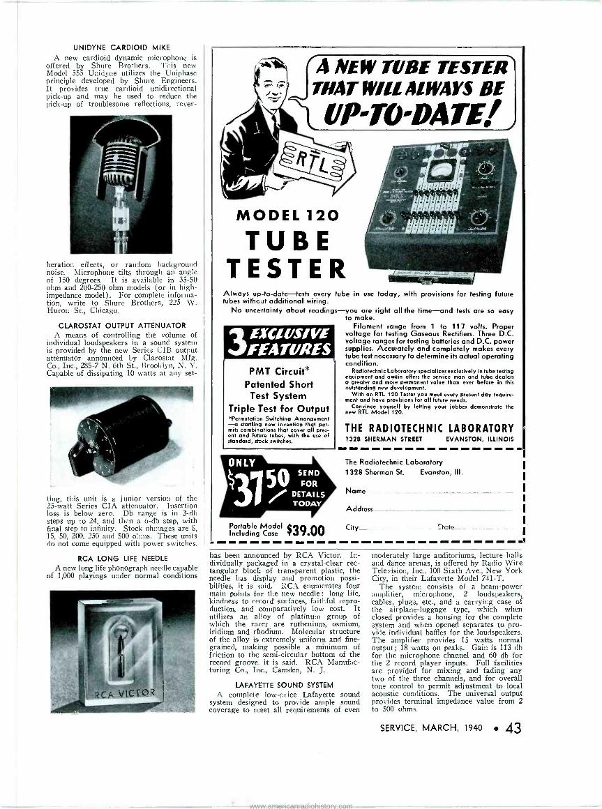
UNIDYNE CARDIOID MIKE
A new cardioid dynamic microphone is offered by Shure Brothers. This new Model 555 Unidyne utilizes the Uniphase principle developed by Shure Engineers. It provides true cardioid unidirectional pick-up and may be used to reduce the pick-up of troublesome reflections, rever-
beration effects, or random background noise. Microphone tilts through an angle of 150 degrees. It is available in 35-50 ohm and 200-250 ohm models (or in high - impedance model). For complete informa- tion, write to Shure Brothers, 225 W. Huron St., Chicago.
CLAROSTAT OUTPUT ATTENUATOR A means of controlling the volume of
individual loudspeakers in a sound system is provided by the new Series CIB output attenuator announced by Clarostat Mfg. Co., Inc., 285-7 N. 6th St., Brooklyn, N. Y. Capable of dissipating 10 watts at any set-
ting, this unit is a junior version of the 25 -watt Series CIA attenuator. Insertion loss is below zero. Db range is in 3 -db steps up to 24, and then a 6 -db step, with final step to infinity. Stock ohmages are 8, 15, 50, 200, 250 and 500 ohms. These units do not come equipped with power switches.
RCA LONG LIFE NEEDLE
A new long life phonograph needle capable of 1,000 playings under normal conditions
A NEW TUBE TESTER THAT WILL ALWAYS BE
UP-TO-DATE1
MODEL 120
TUBE TESTER
Always up-to-date-tests every tube in use today, with provisions for testing future tubes without additional wiring.
No uncertainty about readings-you are right all the time-and tests are so easy to make.
Filament range from 1 to 117 volts. Proper voltage for testing Gaseous Rectifiers. Three D.C. voltage ranges for testing batteries and D.C. power supplies. Accurately and completely makes every tube test necessary to determine its actual operating condition.
Radiotechnic Laboratory specializes exclusively in tube testing equipment and again offers the service man and tube dealers a greater and more permanent value than ever before in this outstanding new development.
With an RTL 120 Tester you meet every present day require- ment and have provisions for all future needs.
Convince yourself by letting your jobber demonstrate the new RTL Model 120.
ExuvsivE FEATURES PMT Circuit*
Patented Short Test System
Triple Test for Output "Permutation Switching Arrangement -a startling new invention that per- mits combinations that cover all pres- ent and Future tubes, with the use of standard, stock switches.
THE RADIOTECHNIC LABORATORY 1328 SHERMAN STREET EVANSTON, ILLINOIS
The Radiotechnic Laboratory 1328 Sherman St. Evanston, Ill.
Name -
Address
Portable Model $39 00 City
Including Case tcte
has been announced by RCA Victor. In- dividually packaged in a crystal-clear rec- tangular block of transparent plastic, the needle has display and promotion possi- bilities, it is said. RCA enumerates four main points for the new needle : long life, kindness to record surfaces, faithful repro- duction, and comparatively low cost. It utilizes an alloy of platinum group of which the rarer are ruthenium, osmium, iridium and rhodium. Molecular structure of the alloy is extremely uniform and fine- grained, making possible a minimum of friction to the semi -circular bottom of the record groove, it is said. RCA Manufac- turing Co., Inc., Camden, N. J.
LAFAYETTE SOUND SYSTEM
A complete low -price Lafayette sound system designed to provide ample sound coverage to meet all requirements of even
moderately large auditoriums, lecture halls and dance arenas, is offered by Radio Wire Television, Inc., 100 Sixth Ave., New York City, in their Lafayette Model 741-T.
The system consists of a beam -power amplifier, microphone, 2 loudspeakers, cables, plugs, etc., and a carrying case of the airplane -luggage type, which when closed provides a housing for the complete system and when opened separates to pro- vide individual baffles for the loudspeakers. The amplifier provides 15 watts normal output ; 18 watts on peaks. Gain is 113 db for the microphone channel and 60 db for the 2 record player inputs. Full facilities are provided for mixing and fading any two of the three channels, and for overall tone control to permit adjustment to local acoustic conditions. The universal output provides terminal impedance value from 2 to 500 ohms.
SERVICE, MARCH, 1940 43
www.americanradiohistory.com
Plan now to attend the
Radio Parts National
Trade Show .Aune 11 to 14
You'll see at first hand what your entire Industry is planning and doing for Fall. You'll get a com- plete prevue of next season's prod- ucts-of Home Recording Devices, Parts, Public Address,Tubes, Labo- ratory Apparatus, Ham Gear, etc. You'll pick up tangible sales and merchandising ideas which you can convert into profits in your own business. Look ahead-plan now to go to the Show. It pays!
JOBBER DAYS Tues., Wed., Thurs., June 11,12,13
OPEN HOUSE Friday, June 14
STEVENS HOTEL, CHICAGO
Radio Parts National Trade Show
53 West Jackson Boulevard Chicago
44 SERVICE, MARCH, 1940
Index to Advertisers
A
Aerovox Corp. 36 Allied Radio Corp 44 American Television & Radio Co 35 Amperite Co. 9 Astatic Microphone Lab., Inc 42
B
Bruno Labs., Inc.
C
Centralab
H
Hygrade Sylvania Corp
J
Jackson Electrical Instrument Co
K
Ren -Rad Tube & Lamp Corp.
M
44
40
18
42
35
Mallory & Co., P. R. Second Cover Meissner Mfg. Co. 19
N
National Union Radio Corp 26, 37 NRPDA 4
O
Oltmite Mfg. Co. 42
P
Permo Products Corp. 39 Precision Apparatus Corp....Third Cover
! R
RCA Mfg. Co., Inc 24, 41, Back Cover Radiart Corp., The 33 Radio City Products Co., Inc. 31 Radio Corporation of America 22, 23 Radio Parts National Trade Show 18, 44 Radio Servicemen of America, Inc..... 38 Radiotechnic Lab. 43 Readrite Meter Works 39 Rider, John F., Publisher 20, 35
S
Solar Mfg. Corp. 35 Sprague Products Co. 27 Supreme Instruments Corp. 29
T
Triplett Elec. Inst. Co., The 40 Triumph Mfg. Co 37
U
United Teletone Corp. 1
Utah Radio Mfg. Co 13
Y
Yaxley Mfg. Division Second Cover
Discs for Home Recording
"The Red Record"
The original paper core instan- taneous recording blank. Dur- able, non -inflammable, flexible and will remain "fresh" indefi- nitely.
NEW LOW PRICES
Package of 9- 6" single face-List $0.75 " " 6- 6" double face-List .75
.75 " 3-10" " " 1.05 " 3-12" 1.75
Deliveries-any quantity- immediately
Manufacturers and Distributors: Place your orders now for prompt delivery. PHONOFLEX CUTTING NEEDLES
Booklat of 10, list $2.50
BRUNO LABORATORIES, Inc. 30 W. 15th St. New York. N. Y.
Sales representatives-some good territories open. Write
ALLIED'S 194(0 S,m4o
CATALOG!
Your Index to Everything in Radio
NEW P.A. 18 New Sound Systems -7 to 75 watts-tor Electioneering, Rentals, Or- chestras. Schools. Churches, etc. New ideas-new anon- cations-new low prices. The easiest Time Payment Plan ever -15 -Day Trial Offer, etc.
Servicemen. See all the new Teat Equipment-all the new service tools and gadgets. More than 15,000 replacement partg will answer every one of your service needs. You'll want to keep this new ALLIED Spring Catalog handy for everything you need in radio! 60 New Sets. Real Radio "Hite"-new "Camera" Port- able; new European reception compacts: plastic phono -radios; recorder combinations - all wonderful gales "leaders." When you do business with ALLIED, you get the best of everything because ALLIED is the 100% Radio House.
ALLIED RADIO CORPORATION 833 W. Jackson Blvd. Chicago, Illinois Dept. 19 -C -O
RUSH me your FREE Spring Catalog.
NAME
ADDRESS
CITY STATE
SEND COUPON NOW!
www.americanradiohistory.com
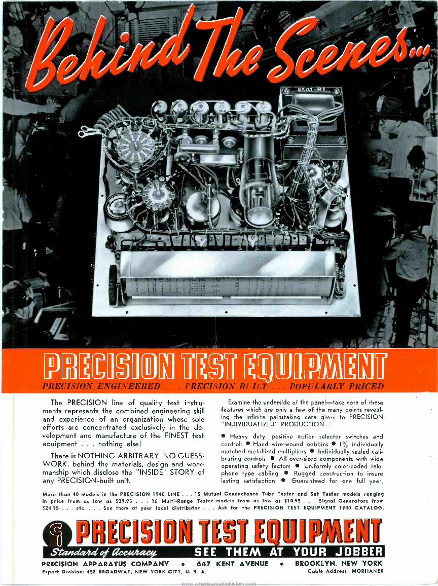
"7'tT.... -
.. Yº :,'-(,;°...
111171PA Uú The PRECISION line of quality test ilstru-
ments represents the combined engineering skill and experience of an organization whose sole efforts are concentrated exclusively in the de- velopment and manufacture of the FINEST test equipment . . . nothing else!
There is NOTHING ARBITRARY, NO GUESS- WORK, behind the materials, design and work- manship which disclose the "INSIDE" STORY of any PRECISION -built unit.
Examine the underside of the panel-take note of these features which are only a few of the many points reveal- ing the infinite painstaking care given to PRECISION "INDIVIDUALIZED" PRODUCTION-
Heavy duty, positive action selector switches and controls Hand wire -wound bobbins I% individually matched metallized multipliers Individually sealed cali- brating controls All over -sized components with wide operating safety factors Uniformly color -coded tele- phone type cabling Rugged construction to insure lasting satisfaction Guaranteed for one full year.
More than 40 models in the PRECISION 1940 LINE . . 15 Mutual Conductance Tube Tester and Set Tester models ranging in price from as low as S29.95 . . . 16 Multi -Range Tester models from as low as 510.95 . . . Signal Generators from 524.95 . . . etc. . . See them at your local distributor . . . Ask for the PRECISION TEST EQUIPMENT 1940 CATALOG.
SEE THEM AT YOUR JOBBER PRECISION APPARATUS COMPANY 647 KENT AVENUE Export Division: 458 BROADWAY, NEW YORK CITY, U. S. A.
BROOKLYN, NEW YORK Cable Address: MORHANEX
www.americanradiohistory.com

The RIDER twiNiursi. 10906
RIDER CHANALYST
$170 net It will pay for itself by
saving your time ...upping your
profits
The Rider Chanalyst estab_ished signal tracing! It was the first instrument of its kind and still is the top instrument! Dollar for dollar the RCA Rider Chan- ælyst offers the most for the money.
The present day RCA Rider Chan- alyst is the result of years of develop- ient based on a wide range of receiver
circuit knowledge, test equipment ap- 1 ication, and country -wide contacts
the servicing fraternity. Every pos- ible arrangement of meters, "eyes,"
4 n d other type indicators was tried. he final version of the RCA Rider hanalyst offers the greatest amount
of utility and flexibility combined with built-in stability and freedom from complicated circuits for the lowest
possible price. For instance: Five sep- arate channels are available simultane- ously, permitting the isolation of in- termittent troubles-the bane of your existence-in the shortest possible time. The RF -IF channel is a 3 -stage tuned r -f amplifier-resonated vacuum tube voltmeter type-assuring ade- quate sensitivity and selectivity. A cali- brated meter-automatically protected against normal overloads-is arranged to function in 4 channels at the option of the operator. "_ he use of inertia -less "electronic eyes" as indicators affords the greatest speed of action for fast servicing since the "eye" provides an easily observed signal level permitting stage gains to be read directly from
level control. No loss of speed or effi-
ciency in the shop should an indicating device become inoperative as "eyes" can be locally replaced.
The RCA Rider Chanalyst permits circuit signal condition checks rather than the time-consuming cut and try part removal and checking. Compli- cated circuits become as easy to ser- vice as the simplest.
The RCA Rider Chanalyst is already being used by more than 3000 pro- gressive members of the servicing fra- ternity in the relatively short time since its appearance. These men are finding the RCA Rider Chanalyst is making servicing more profitable. Before you buy-ask the man who uses one!
Over 335 million RCA Radio Tubes have been purchased by radio users ...in tubes, as in parts and test equipment, it pays to go RCA All the Way.
irt-/ti,)vete,#74- RCA Manufacturing Co., Inc., Camden, NI. J. A Service of the Radio Corporation of America
www.americanradiohistory.com


![Louie’s Hungry Five: The Radio Work of Henry Moeller and ...s Hungry Five.pdf7 Radio Digest confirms that “last October [1930] Moeller and Gilles [Herr Louie and the Weasel, respectively]](https://img.pdfslide.net/doc/110x75/5f59a37d7dde4c6aac24789a/louieas-hungry-five-the-radio-work-of-henry-moeller-and-s-hungry-fivepdf.jpg)


![Allied Telesyn Government Allied Telesyn Centrecom Manual[1]](https://img.pdfslide.net/doc/110x75/547ef4015806b5d15e8b47a8/allied-telesyn-government-allied-telesyn-centrecom-manual1.jpg)