Embed Size (px)
Citation preview

74 Philips tech. Rev. 36, 74-84, 1976, No."3
A fast actuator for an anti-lock braking system
D. R. Skoyles
It is very important for road safety that cars shouldnot skid when the brakes are appliedsuddenly. There is a danger of this on wet or icy roads, where the wheels can easilybecome locked. To prevent thisfrom happening various anti-lock braking systems havebeen developed. This article describesan electro-hydraulic brake-pressure control with anumber of new features. It was initially developed for testing electronic circuits foranti-lock systems and the design has given such good results in trials that it has beentaken as the starting pointfor thefurther development of anti-lock braking systems.
Introduction
When the brakes of a vehicle are applied a certainamount of 'slip' must occur between the wheels and theroad. The word 'slip' is used here as an indication thatthe braked wheels rotate more slowly than they wouldif they rolled freely [*1. When the brakes are first ap-plied, the wheels continue to roll over the road, but therate of rotation decreases because of the elastic defer-mation in the part of the tyre that forms the contactpatch on the road surface. As the brake pressure in-creases, the speed of the wheels relative to the roaddecreases and eventually the wheel will lock. Thedegree of slip as the wheel approaches lock is a com-plicated function of the characteristics of the brake,the tyre and the road surface. Other factors such as thespeed and deceleration of the vehicle also come intoplay.
When the wheelsof a vehicle are locked, the stoppingdistance generally becomes larger, and if the frontwheels are locked, steering becomes impossible. Mostdrivers are fully aware of this frightening loss of con-trol and do not attempt to apply the brakes fully if theroad surface appears to be slippery. Even experiencedprofessional drivers are unable to brake at the maxi-mum value as they cannot allow for the difference incharacteristics from wheel to wheel.
In the interests of safety it is clear that wheel lockshould be avoided. Some way must therefore be foundof preventing the brakes from being applied too hard.If this can be done automatically, a driver would beable to brake fully in an emergency, while full steeringcontrol and normal handling will be maintained.Many practical solutions to this problem have beenproposed: a few of them are now in use on a limitedscale. This article describes a hydraulic pressure con-D. R. Skoy/es, M./.E.E., is with Mullard Research Laboratories,Redhill, Surrey, England.
trol or actuator for an anti-lock system; the device wasdevised and constructed for testing electronic controlmodules for such a system in a vehicle. At the timethere was no existing actuator with a fast enoughresponse for the purpose. The actuator was initiallydeveloped for private cars, but it may well be suitablefor other vehicles. Many features of this actuator areused in more recent anti-lock systems under develop-ment.Before we begin the actual descriptions of the design
and construction ofthe actuator, we should first consid-er the behaviour of a skidding vehicle, tyre charac-teristics and the arrangement of anti-lock systems.
Construction and use of anti-lock systems
There are three fundamental parts to any anti-locksystem: a sensor that measures the wheel speed (orsome related speed), a processor unit (typically elec-tronie or fluidic) and a mechanical actuator that canbriefly reduce the brake pressure and then restore itagain as long as there is pressure in the master cylinderof the braking system. The wheel sensor may measurethe speed of a single wheel or of a number of wheels.The output quantity is a signal whose frequency orvoltage is proportional to the wheel speed. This signalis applied to the processing unit, where it is used topredict an imminent wheellock. If necessary, the out-put signal from the processor is made to operate asolenoid valve or other actuator to reduce the brakepressure. More than one such actuator may be used.In most anti-lock systems the brake force falls whilethe solenoid (or other device) is energized, and in-creases when the solenoid is switched off (after thedanger of a wheel lock has passed). Since the passivestate of the pressure regulator corresponds to normal

Philips tech. Rev. 36, No. 3 ANTI-LOCK BRAKING SYSTEMS 75
F, ._.-._. OT.__ .__ .-_. __ .__ .__ .__ .__ .-_. __ ._-.-_.
AFig.!. Illustrating the behaviour of a vehicle if wheels become locked during braking.
braking, a certain measure of fail-safe behaviour isautomatically built into the system.Ideally the combination of sensor control circuit and
actuator would be fitted to each wheel separately,allowing each tyre to have the optimum grip on theroad. This would give the driver maximum braking andsteering control, but it is costly. In many existing sys-tems a single actuator is used to control one axle or onepair of wheels. In such cases the control must beapplied to the rear wheels, as the following argumentshows.Although an anti-lock system will in general reduce
the stopping distance, its most important function isto prevent loss of control of the vehicle. At first sightit would appear that it is more important to prevent
B
Ps _-"<--.M ....
P4+=~~==P3-_"L.k,~
the front wheels from locking, since these do the steer-ing. (This would also appear to give a shorter stoppingdistance, since most of the braking force is provided bythe front wheels owing to weight transfer.) This is notso, however: a moving vehicle with a single pair ofwheels locked will eventually travel in the originaldirection but with the rolling pair of wheels trailing [11.
If only one pair of wheels is to be controlled, it musttherefore be the rear wheels.The behaviour of a vehicle when wheels are locked during
braking will be discussed with the aid of fig. 1. The vehicle istravelling along the line AB. It is assumed that only the rearwheels lock, at the instant when the centre of gravity of thevehicle is at the point PI. If the long axis of the vehicle nowdevi~tes slightly from AB, the front of the vehicle starts to move
. in the 'direction determined by the position of the front wheels,while the centre of gravity of the vehicle continues to move in thedirection AB and the locked rear wheels can skid equally in any
direction. If the driver now keeps the front wheels pointing in adirection parallel to AB, the vehicle continues to move with itslong axis parallel to AB until it comes to a stop. This motion isvery unstable, however, and requires great skill on the part of thedriver. Ifthe driver does not alter the position ofthe front wheels,then small random deviations will cause the vehicle to move in adirection other than AB, e.g. at right angles to OIFI. The centreof gravity continues to move along AB, i.e. at right angles toOIPI. The vehicle therefore describes a circle, centred on 0, andstarts to rotate in a clockwise direction at an angular velocitydirectly proportional to the velocity in the forward direction andinversely proportional to the radius OIPI. After a short time thecentre of gravity of the vehicle has moved to P2; the deviation ofthe front with respect to AB has become larger and the centre ofthe rotation has moved to 02. Since 02P2 < OIPI the angularvelocity ofthe rotation has increased. In this way the vehicle goesvia position 3 to position 4, where it makes an angle of 90° withthe original direction. Here the front is stationary for an instant
and the vehicle rotates about the centre of the front axle. Inposition 5 the rear wheels move in front and the centre of therotation is at 05, while the radius OsPs now becomes greater andthe angular velocity decreases. In position 6 the vehicle is almostin stable motion again, parallel to AB, but with the locked rearwheels in front. A number of second-order effects have beenneglected in this qualitative description [21.
If anti-lock control is applied to the rear wheels only, the frontwheels will lock and skid when the vehicle is strongly brakedunder adverse conditions. If the long axis of the vehicle now
[*1 This is the technical definition of slip, which we shall use inthis article. A sliding movement of a car with locked wheelswill be called 'skid'.
[11 H. Darwin and C. V. Burton, Side-slip in motor cars,Engineering, Sept. 1904.G. Jones, The skidding behaviour of motor vehicles, Proc.Auto. Div. Instn. Mech. Engrs 1962/63, No. 1.
[21 Fig. I and the associated explanation are mainly taken from:J. Bradley and S. A. Wood, Factors affecting the motion of afour-wheeled vehicle when some of its wheels are locked,Proc. Instn. Auto. Engrs 25, 59-62, 1930/31. .

76 D. R. SKOYLES Philips tech. Rev. 36, No. 3
deviates slightly from the direction of travel, the frictional forcesbetween the front tyres and the road ill the directton of motion wil!produce a torque that will tend to swing the vehicle further round.However, the transverse forces on the rolling wheels (the rearwheels here) will set up a much larger torque, tending to restorethe long axis of the vehicle to the direction of travel.
The tyre-road interface
Since rubber is elastic, the tyre and the tread havea certain flexibility, and this has an influence on thefriction between tyre and road [3l. Fig. 2 shows, greatlyexaggerated, the deformation of the rubber where thewheelcontacts the road during braking.As a point on the tyre periphery moves into the
contact patch its effective distance from the centre ofthe wheel decreases and it is at the same time subjectedto a shear force which distorts it. The distortion is afunction of both the shear (retarding) force and theweight acting on the wheel. For a given weight, thereis an instant when the distortion with increased brakingreaches a maximum value at which it is too great to bemaintained by the frictional drag of the road surfaceand at this point sliding of the rubber occurs. Break-away and consequently sliding begin first at the rearedge of the contact patch where the distortion isgreatest and the vertical contact force lowest. As theretarding force increases, the tread distortion increasesand the break-away spreads towards the centre of thepatch, where the vertical contact force is greatest.Eventually, as the brake pressure increases further, theshear force inevitably reaches a value which causessliding even at the centre [4l. Before this point isreached the retarding force available is always increas-ing but once the sliding area has grown sufficiently toinclude the centre of the original contact patch, theforce from the gripping rubber drops rapidly as slidingstarts, lowering the friction force from the static to thesliding value. This decreases the effectiveness of thefront part of the contact patch. The action is cumula-tive: increase of sliding area results in still lowerrestoring forces and the wheel rotation rapidly degen-erates to the locked condition. This process is illustratedin fig. 3 where vehicle retarding force and brakingpressure are plotted against time.
The laws of friction impose upper limits on the maxi-mum retardation forces available at the tyre-roadinterface. For a typical tyre on a good, dry level sur-face a vehicle retardation of about 0.8 g is possible.(1 g is the acceleration due to gravity.) This figure isindependent of the tyre contact area and of the massof the vehicle.
Fig. 4 shows how the angular retardation ë achievedon various surfaces depends on the slip [5l. The slip Sis' defined by:
Fig. 2. Distortion of a tyre by the drag of the road when a wheelis braked. C represents the contact patch and the arrow rep-resents the direction of motion of the vehicle. The dashed linesrepresent radial planes through the centre of the wheel; the solidlines show schematically how these planes are distorted when thewheel is braked. Part of the distortion lies in the side wall of thetyre and part in the tread. The distortion is greatest near the rearof the contact patch.
-tFig.3. Variations of the frictional force between tyre and roadsurface for increasing brake pressure. The frictional force Fr andthe brake pressure Pb are plotted in arbitrary units. At R there isstill complete grip of the road surface; C indicates the pointwhere the break-away from the road surface has expanded toinclude the centre of the contact patch. The wheel then locks andFr decreases to the constant value that applies for the slidingtyre. .
where Bw is the actual angular velocity of the wheel andBv is the angular velocity the wheelwould have if rollingfreely.Although other measurements could give results
somewhat different from those of fig. 4, it is in generaltrue that if wheel slip could be held between 12 and15%, a retarding force would be available which (onmost surfaces) would be higher than the retardingforce available from a locked wheel. .

Philips tech. Rev. 36, No. 3 ANTI-LOCK BRAKING SYSTEMS 77
The retardation-slip characteristics show that evenlight braking (low retardation) is accompanied by acertain amount of wheel slip. This does not necessarilyimply sliding as such, but each part of the rubber treadis distorted as it forms a part of the contact patch dur-ing braking and each new distortion occurs at theexpense of the angular velocity of the wheel. Thisproduces a rotation which is slower than that of afreely rolling wheel.
The higher the peak retardation ratio (= peak retar-dation divided by retardation at S = 100%, see fig. 4),the greater the increase in stopping power given by agood anti-lock system. On wet slippery surfaces thepeak retardation ratio of the slip characteristic (fig. 4)depends on the ability of the tyre tread to breakthrough or squeeze out the moisture film between rub-ber and road. Since this is more difficult at high speeds,the peak of the slip characteristic has a value whichdecreases with speed. It is also very dependent on tyre-tread design and surface texture. A worn tyre with atread of less than 1-2mm has inadequate drainage [6]
. and the braking force on a smooth wet surface istherefore less than that with a full tread. A rough roadsurface allows improved drainage and the differencebetween a worn and an unworn tread is less marked.Experiments have shown that tread is unimportant onnormal dry surfaces, where even bald tyres give excel-lent performance.A good, dry road surface offers higher road adhe-
sion and higher braking torques are possible withoutthe danger ofwheellock. Fig. 5 shows some slip charac-teristics for various road surfaces. The retarding torque
ij
t
5
6II
0 120 40 60 80 700%75 -s
Fig. 4. Retardation-slip characteristics of various road surfaces,showing that the peak retardation is mostly attained for a slipof between 10 and 15%. 1 dry asphalt, 2 wet asphalt (thin waterfilm), 3 wet asphalt (thick water film), 4 fresh snow, 5 packedsnow,6ice.
given by the road-tyre drag is plotted (instead of theretardation) as a function of the slip S.When the high-slip region of the torque-slip curve
is nearly horizontal, the retarding force of the lockedwheel is not greatly different from the peak brakingtorque near 15% slip. In this situation the reduction inbrake pressure that the anti-lock device must provideto allow the wheel to recover to the stable side of thecurve must in fact be less than in the case of a steeperslip characteristic. The way in which the anti-lockdevice reduces the brake pressure will be discussed inthe next section.Gravel surfaces and loose snow behave anomalously
(see figs. 4 and 5) because the material piles up in frontof the wheels.
T,-
t
Fig.5. Braking torque Tr available on various surfaces as func-tion of the slip S. 1 good surface, 2 gravel (the hump is due topiling up). If T; is the braking torque at which the wheel startedto lock on a good surface, a small rednetion I5T to Tr will returnthe wheel to a safe braking condition. The same torque reductionwould be inadequate for a more slippery surface, as can be seenfrom curve 3.
Principles of anti-lock systems
Before discussing the principles on which an anti-lock system can be designed, it is important to recog-nize the surprising fact that one essential piece of infor-mation - the true road speed of the vehicle - is notreadily available. As we sawearlier, the peripheralspeed of the wheel is only equal to the road speed ifthere is zero slip. As soon as slip appears, the two speedsdiffer. The wheel speed can easily be measured by atransducer at the wheel.To determine the slip, however,the actual speed relative to the road must be known.Apart from such obvious methods of measurement as
[3] G. Temple, The dynamics of the pneumatic tyre, Endeavour15, 200-205, 1956.
[4] K. N. Chandler, Theoretical studies in braking, Part I: Effectsof longitudinal slip for a single wheel, Proc. Auto. Div.Instn. Mech. Engrs 1960/61, No. 4. .
[5] P. Müller and A. Czinczel, FISITA 14th Congress, London1972, p. 3/92.
[6] G. C. Staughton, The effect of tread pattern depth on skiddingresistance, Report of the Transport and Road ResearchLaboratory LR 323, 1970.

78 D. R. SKOYLES Philips tech. Rev. 36, No. 3
a fifth wheel (not acceptable for private cars), or morecomplex methods such as Doppler radar (too expen-sive), there is no simple way of doing this. The road-speed information necessary for anti-lock control -or some approximation to it - must therefore beextracted in another way.
An estimate of the minimum road speed at any giveninstant can be derived from the wheel speed at themoment the brake is applied and an assumed maximumattainable deceleration of the vehicle. This can beconveniently obtained electronically by using a voltageproportional to the wheel speed and a circuit in whichthe maximum deceleration is simulated. This circuitgives a reference voltage proportional to the estimatedroad speed. The voltage corresponding to the instan-taneous wheel speed is now compared to the abovereference voltage. If it is less than 85% of this value thismeans that the slip of the wheel is excessive.The best possible braking would be obtained if the
brake pressure could be always held at the valuecoinciding with the maximum retarding force availableat each instant from the road (see figs. 4 and 5). If thewheel is held at this 'state of maximum adhesion' themaximum lateralor steering force is in general ob-tained [71. In practice the optimum brake pressurecannot be used because .regulating the pressure to this(changing) optimum value requires the true slip of thewheel to be known accurately at every instant. Itmightappear that a good compromise would be to regulatethe brake pressure at a level lying at a more stablepoint just below the peak adhesion region of theretardation-slip curve (fig. 4). However, this also turnsout to be impracticable because of the variation inroad-surface friction, and there are also problems oflong-term stability. In practice the pressure is therefore'modulated' about the optimum, i.e. cycled about thepoint of maximum adhesion, high slip values causing areduction of mean pressure. This allows for varyingsurfaces and changes of weight between the wheels.Since lower slip values arise repeatedly, a fairly simplemethod can be used for supplying the electronic controlmodule with regularly updated computed informationabout the wheel slip: this information is essential fordetermining the correct instants for the relaxation andre-application of the brake pressure.
For a level-force-slip characteristic (fig. 5, curve 1), reductionto below the locking pressure may appear to provide a brakingforce lower than that of a locked wheel but this is not necessarilyso. The pressure may be modulated about a value well below theoptimum pressure, without any reduction in the average vehicle-retarding force. Wheel inertia plays an important part here. Thefollowing statement may help to clarify this: if the vehicle is mov-ing fast with all wheels locked owing to excessive brake pressureand the brake pressure is instantaneously reduced to zero, full
'braking' is maintained until the wheels have been accelerated(by the road) to about 85% of the vehicle speed (i.e, about 15%slip). The retarding f~rce after zero brake pressure is producedhere not by brake torque but by wheel inertia.The sum of the torques acting on the wheel is zero:
Tr + Tb + të; = 0,
where Tr is the road torque, Tb is the brake torque, 1 is the mo-ment of inertia of the wheel and ë; is the angular acceleration.When the brakes are applied, the stored energy of the vehicle isreduced but so is the stored energy of the wheels as they decreasein speed. When the brakes are released the acceleration of thewheels by the road is associated with an inertial reaction torque
9
tQ
IJ
t
t
Fig. 6. a) The angular velocity Ö of the wheel, plotted as a func-tion of time. ev represents the vehicle road speed expressed interms of the angular velocity of a (hypothetical) freely rotatingwheel. For t < to the speed is constant; at t = to the brakes areapplied. The deceleration iJ~of the vehicle, which is given by theslope of the curve ev, then changes from (jv = 0 to ëv = -K,where K is "assumed constant. The maximum value of K in prac-tice is found to be about 0.8 g. When the brakes are applied thereis always some slip. The curve ë; shows how the wheel speedwould vary in the ideal case, i.e. braking such that the slipremains between 10 and 15% (see the peak retardation in fig. 4).b) Variations of the true wheel speed Ow. The upper dashed lineis the tangent to the curve tiw at a point where the slope ijw corre-sponds to a deceleration of 1.5g. This line is the velocity reference.The lower line is drawn parallel to the upper line and below itsuch that the distance S' represents a 5% slip with respect to thevelocity references. This implies that at the time t"l the decelera-tion ofthe wheel is well in excess ofthe reference at 1.5 g; at thispoint the solenoid valve is energized. c) The variation of thebrake pressure Pb with time, as controlled by the energization ofthe solenoid valve. (The shape of this curve is discussed later inthis article, with the construction of the valve.) At tOl thesolenoid valve is de-energized. '02' 102 etc. are subsequent cyclesof operation.

Philipstech, Rev. 36, No. 3 ANTI-LOCK BRAKING SYSTEMS 79
liJ',. which has the same sense as Tb. The energy required to buildup this torque is extracted directly from the kinetic energy of thevehicle.
Many anti-lock control devices make use of the wheel inertiaeffect; it is a feature which greatly facilitates the realization ofpractical systems.
When the control circuit detects a potential wheellock, a solenoid valve is opened to relieve the brakepressure. After a certain inevitable delay, the grip ofthe brake on the wheel will have decreased sufficientlyfor the drag force of the road to re-accelerate thewheel: the slip therefore starts to decrease again. Whenthe slip has been sufficiently reduced, the brake pres-sure can be increased again by closing the solenoidvalve. The whole process - detection of excessive slip,opening of solenoid valve and closing it - is nowrepeated as shown schematically infig. 6a, band c. Thebrake pressure and the slip are thus continually cycledabout the point of maximum adhesion (fig. 4).
The first energization of the solenoid valve takesplace just after the wheel has been decelerating at arate greater than that corresponding to a vehicledeceleration of 1.5 g (well above the maximum vehicledeceleration attainable). Actual switch-on occurs when
\/"9
, (Vó(t')~Vc-Vö (t)- -- t- RC
t
Fig. 7. a) Elementary circuit for the comparison of the wheel-speed sensor voltage with an artificial reference corresponding toa wheel deceleration of 1.5 g. The output voltage Vó from thewheel sensor (a voltage generator) is proportional to the wheelspeed, VB = k{Jw. The capacitor is charged to this voltage via thediode but the charge leaks away at a rate determined by CR.Rand C are chosen such that the charging rate corresponds to adeceleration of 1.5 g. b) Variations of the voltage Vó from thewheel sensor. As soon as the wheel deceleration is lower than1.5 g the voltage Vc across C is equal to Vó, butifthe decelerationexceeds 1.5 g (at time t'), Vó falls below Vc. A sensing circuitgives a signal if the voltage Vs becomes negative, i.e. if VB fallsbelow 0.95 Vc (the line VO.05).This signal is used to energize the
.. anti-lock solenoid (at the time tel)' The slip is then about 5 %'greater than it was when the reference was first exceeded. Theenergization is removed again at the time tOl when VB again be-comes larger than VO.05.
the wheel slip amounts to more than 5% relative to 'thereference speed corresponding to a deceleration of1.5 g (hence at time tel in fig. 6b). This is not the idealinstant for the start of the energization, but the actualslip will be greater than 5% since vehicle decelerationwill always be far lower than 1.5g, and the vehiclespeed will always be above the computed reference.
The slope of the ideal curve {Jw in fig. 6a corresponds to awheel-speed control such that there is always 15% of slip, i.e.such that {Jw remains continuously 15% below the curve ev. Itmight appear to be better to wait until the wheel speed haddropped to the value corresponding to 15% slip (maximum adhe-sion) before energizing the solenoid to relieve the brake pressure,but in practice it is more advantageous to energize as soon aspossible in the case of rapid brake application (slow applicationallows the desired slip value of 15% to be reached). In addition,it is more convenient to operate with a single slip setting for thewheel sensor (the tapping in fig. 7a, see below). When the slip ofthe wheel begins to decrease (re-acceleration to the vehicle speed)the brake pressure has to be re-introduced sufficiently slowly toenable the wheel to reach the stable side of the curve to the left ofthe peak in fig. 4). A repetitive pressure-cycling actio'n is thenpossible. If the stable side of the curve were' not reached, thecontrol circuit would not get enough information to assess theslip and the wheel would lock.
Fig. 7a gives a highly simplified example of a circuitin which the artificial reference voltage correspondingto a vehicle deceleration of 1.5 g is compared with thevoltage from the wheel-speed sensor. This voltage Vil,which is always proportional to the wheel speed Ow,is applied to the capacitor C via a diode. A resistanceR is connected across the capacitor, giving a constantRC corresponding to a deceleration of 1.5 g (RC isusually greater than the cycle time fe2 - tel):
(t ) VoV = Vo e-t/CR R:I Vo 1- - = Vo - - t.
RC RC
The voltage across R cannot therefore fall faster thanV = vsmc, see the line Vc in fig. 7b.For a given wheel speed Bw, a voltage Vil= kow is
generated. The capacitor is charged to this voltage,which therefore appears across R. On sudden braking,the wheel velocity can fall faster than the fixed rateV = Vo/RC, which is made to correspond to a vehicledeceleration of about 1.5 g. Whenever this happens weknow that ëw has a value larger than that correspond-ing to 1.5 g. The solenoid valve is energized if thevoltage Vö falls below the voltage at a tapping on Rcorresponding to 0.95 R (at the time tel' if the curvesViland VO.95 intersect). This will occur at a slip value5% in excess of the reference line. When the speed ofthe wheel has increased again such that Vö > VO.95 (attime tOl)' the solenoid valve is de-energized, and the
[7J K. E. Holmes and R. D. Stone, Tyre forces as functions ofcornering and slip on wet road surfaces, Report of the Trans-port and Road Research Laboratory LR 254, 1969.

80 D. R. SKOYLES Philips tech. Rev. 36, No. 3
whole cycle is repeated again if required. The circuitsused in practice are more complex to allow for a con-stant slope at allwheel speeds and also to accommodateall kinds of delays and second-order effects.
An actuator for an anti-lock system
The actuator used has the form shown in jig. 8. Itconsists of a solenoid valve, a variable restrictor and apump. The pump is driven directly by the wheel.
The actuator was designed with the seven followingaims in view:It should be a small compact unit which can be housedwithin the wheels (no vulnerable pipes or signal wiresacross the vehicle, potential sources of failure).The actuator should not affect the normal operation ofthe brakes.The instant at which the brakes are reapplied shoulddepend, on the decrease in slip during an anti-lockperiod and also on anti-lock behaviour during pre-vious cycles.The brake pressure should not be allowed to fall so farthat under-braking results when the wheel is freedfrom lock.Fail-safe arrangements should be included in case ofcircuit or wiring failures or other faults.There should be a single solenoid valve for brake-pressure control.The control system should be completely independentof the driver.Incipient wheel lock causes the control circuit to
open the solenoid valves and hence reduce the brakepressure. When the wheel has recovered to a safecondition (left-of-peak in fig. 4) the solenoid is closedand the fluid that has flowed from the brake cylinder Bis returned to the pressurized master cylinder M. If thiswere not done the drivers' foot would continue tomove towards the floor in an effort to maintain thepressure in a 'leaking' system. At the same time thepressure in the brake cylinder increases again. To obtainthe maximum braking this should happen as quicklyas possible; the rate of pressure build-up should not beaffected by. factors other than the behaviour of thewheel.
The variable restrictor
On a good road surface the wheel can recover speedrapidly because of the high frictional drag of the roadon the tyre. For this reason a higher rate of pressurerecovery is required on a good surface than on a poorsurface. This is arranged by.designing the actuator insuch a way that the pressure-recovery rate is a functionof the total time for which the solenoid has beenenergized. This is done by the variable restrictor V
(fig. 8). The longer the solenoid is opened (poorer sur-face) the more the cylinder D with the plunger h isdriven to the right and the slower the build-up of pres-sure in the brake after the solenoid has closed again.On a good road surface the wheel recovers its speedvery rapidly after a high slip: the solenoid is onlyenergized for a short time and the plunger hardly
Fig. 8. The anti-lock braking system. The actual braking systemconsists of the master cylinder M and the brake cylinder B thatoperates the brake of a wheel. The main parts are a solenoid valveS which relieves the brake pressure when the wheel is about tolock, a variable annular restrictor Vwith plunger Ji, which deter-mines the rate of pressure build-up in the brake after the solenoidvalve has closed again, and a pump P which returns divertedbrake fluid to the master cylinder. The pump can be located inthe wheel and driven by it. F is a fail-safe control valve whichcloses in the event offaulty operation of S. R is a reservoir for thediverted brake fluid; this brake fluid displaces the piston D, sothat the quantity of fluid in R determines the amount of closureofthe restrictor V (see also fig. 9).h is a second plunger mountedon D, which modifies the rate of brake-pressure recovery.
Fig. 9. Pressure in the brake cylinder decreasing as a function oftime, and its dependence on the solenoid energization time. terepresents the instant at which the solenoid is energized. There isfirst a slight delay -,; before the pressure begins to drop (a fewmilliseconds). If the energization continues for a long time thepressure can drop to pmin. A typical energization lasting for atime (ra - te) allows a build-up of pressure at the rate indicatedby the angle r after the solenoid has closed. A shorter energizationresults in a more rapid pressure build-up. Longer energizationsare accompanied by a slower increase until te is exceeded. At thistime the reservoir R (fig. 8) is full and pressure would be restored,in the absence of pump P, even if the solenoid remained ener-gized. If, however, the pump was operating, all fluid would bereturned to the master cylinder and no pressure build-up wouldbe possible until the solenoid was de-energized.
Philips tech. Rev. 36, No. 3 ANTI-LOCK BRAKING SYSTEMS 81
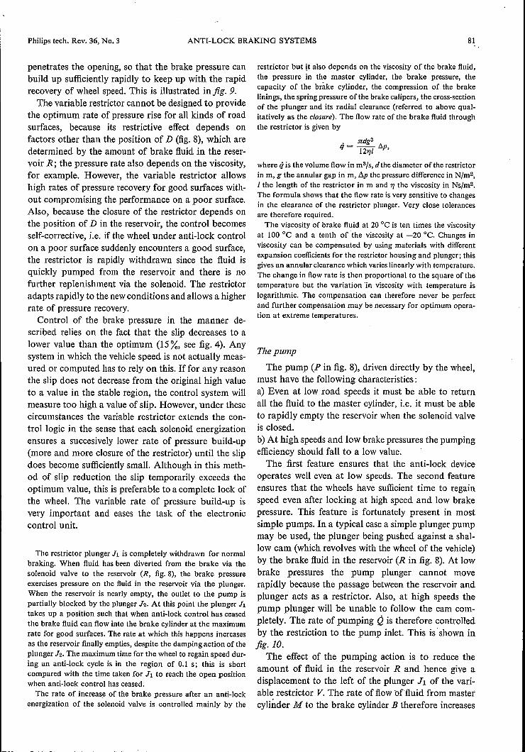
penetrates the opening, so that the brake pressure canbuild up sufficiently rapidly to keep up with the rapidrecovery of wheel speed. This is illustrated infig. 9.The variable restrictor cannot be designed to provide
the optimum rate of pressure rise for all kinds of roadsurfaces, because its restrictive effect depends onfactors other than the position of D (fig. 8), which aredetermined by the amount of brake fluid in the reser-voir R; the pressure rate also depends on the viscosity,for example. However, the variable restrictor allowshigh rates of pressure recovery for good surfaces with-out compromising the performance on a poor surface.Also, because the closure of the restrictor depends onthe position of D in the reservoir, the control becomesself-corrective, i.e. if the wheel under anti-lock controlon a poor surface suddenly encounters a good surface,the restrictor is rapidly withdrawn since the fluid isquickly pumped from the reservoir and there is nofurther replenishment via the solenoid. The restrictoradapts rapidly to the newconditions and allows a higherrate of pressure recovery.
Control of the brake pressure in the manner de-scribed relies on the fact that the slip decreases to alower value than the optimum (15%, see fig. 4). Anysystem in which the vehicle speed is not actually meas-ured or computed has to rely on this. If for any reasonthe slip does not decrease from the original high valueto a value in the stable region, the control system willmeasure too high a value of slip. However, under thesecircumstances the variable restrictor extends the con-trol logic in the sense that each solenoid energizationensures a succesively lower rate of pressure build-up(more and more closure of the restrictor) until the slipdoes become sufficiently small. Although in this meth-od of slip reduction the slip temporarily exceeds theoptimum value, this is preferable to a complete lock ofthe wheel. The variable rate of pressure build-up isvery important and eases the task of the electroniccontrol unit.
The restrictor plunger 11 is completely withdrawn for normalbraking. When fluid has been diverted from the brake via thesolenoid valve to the reservoir (R, fig. 8), the brake pressureexercises pressure on the fluid in the reservoir via the plunger.When the reservoir is nearly empty, the outlet to the pump ispartially blocked by the plunger Jz. At this point the plunger 11takes up a position such that when anti-lock control has ceasedthe brake fluid can flow into the brake cylinder at the maximumrate for good surfaces. The rate at which this happens increasesas the reservoir finally empties, despite the damping action of theplunger J2. The maximum time for the wheel to regain speed dur-ing an anti-lock cycle is in the region of 0.1 s; this is shortcompared with the time taken for 11 to reach the open positionwhen anti-lock control has ceased.
The rate of increase of the brake pressure after an anti-lockenergization of the solenoid valve is controlled mainly by the
restrictor but jt also depends on the viscosity of the brake fluid,the pressure in the master cylinder, the brake pressure, thecapacity of the brake cylinder, the compression of the brakelinings, the spring pressure of the brake calipers, the cross-sectionof the plunger and its radial clearance (referred to above qual-itatively as the closure). The flow rate of the brake fluid throughthe restrictor is given by
• ndg3
q = 121]1 /::"p,
where ti is the volume flow in m3/s, d the diameter of the restrictorin m, g the annular gap in m, !1p the pressure difference in Nfm2,
1 the length of the restrictor in m and 1] the viscosity in Ns/m2•
The formula shows that the flow rate is very sensitive to changesin the clearance of the restrictor plunger. Very close tolerancesare therefore required.The viscosity of brake fluid at 20 DCis ten times the viscosity
at 100 DC and a tenth of the viscosity at -20 DC. Changes inviscosity can be compensated by using materials with differentexpansion coefficients for the restrictor housing and plunger; thisgives an annular clearance which varies linearly with temperature.The change in flow rate is then proportional to the square of thetemperature but the variation 'in viscosity with temperature islogarithmic. The compensation can therefore never be perfectand further compensation may be necessary for optimum opera-tion at extreme temperatures.
The pump
The pump (P in fig. 8), driven directly by the wheel,must have the following characteristics:a) Even at low road speeds it must be able to returnall the fluid to the master cylinder, i.e. it must be ableto rapidly empty the reservoir when the solenoid valveis closed.b) At high speeds and low brake pressures the pumpingefficiency should fall to a low value.The first feature ensures that the anti-lock device
operates well even at low speeds. The second featureensures that the wheels have sufficient time to regainspeed even after locking at high speed and low brakepressure. This feature is fortunately present in mostsimple pumps. In a typical case a simple plunger pumpmay be used, the plunger being pushed against a shal-low cam (which revolves with the wheel of the vehicle)by the brake fluid in the reservoir (R in fig. 8). At lowbrake pressures the pump plunger cannot moverapidly because the passage between the reservoir andplunger acts as a restrictor. Also, at high speeds thepump plunger will be unable to follow the cam com-pletely. The rate of pumping Q is therefore controlledby the restrietion to the pump inlet. This is' shown infig.Jt).
The effect of the pumping action is to reduce theamount of fluid in the reservoir R and hence give adisplacement to the left of the plunger Jl of the vari-able restrictor V.The rate of flow of'fluid from mastercylinder M to the brake cylinder B therefore increases

82 D. R. SKOYLES Philips tech. Rev. 36, No. 3
as pumping continues and this enables the system toadapt to a good surface after having been on a poorsurface. High vehicle speed would theoretically givescavenging (emptying) of R at too high a rate (thescavenging rate is proportionalto the speed) but therestrictive effect of JI and the connection between Rand P (fig. 8) is sufficient to limit this to a suitable valuewithout the necessity for any additional impedance.
d
t
- ê(rad/s)Fig. 10. Illustrating the pumping rate Q as a function of wheelspeed e, at various positions of the plunger J2 (fig. 8). CurvesJ, 2, 3 are for high and medium brake pressures, showing thepumping rates Q attainable when the plunger Jz permits full flow.The line Qm represents the maximum pumping rate when theplunger does limit flow. Curves 4 and 5 represent the rates forlow brake pressures.
The solenoid valve
When not energized the solenoid valve is closed. Atpressures up to about 20 000 kNfm2 (3000 p.s.i., 200atm) it completely prevents the flow of fluid. Whenenergized it must release fluid at a rate which permitsa brake-torque decay rate of about 2100 Nm/s and,equally important, when de-energized it must interruptand stop the flow of fluid very rapidly. The operatingcurrent for the solenoid has to be provided by the carbattery and in practice this means that the maximumcurrent is about 10 A. The armature pull-in timeshould be below 7 ms at this current and any reductionof this time improves the braking performance.The anti-lock system described here uses a solenoid
with a flow control which allows an initial rapid dropof fluid pressure corresponding to a decrease in braketorque of 180 Nm, followed by a linear fall rate corre-sponding to 14000 Nmfs (matched to the brakes ofthetest vehicle). If the initial drop in pressure alone deter-mined the 'modulation depth' (the relative decrease in.brake pressure, see fig. 6c) this would give rise to± 17% of modulation on a dry surface (coefficient offriction p, R:! 1) and ± 100% modulation on a slipperysurface (p, ÄJ 0.15). ,!he large modulation depth isnecessary on slippery surfaces for the wheel to recover
------------~--------------
its speed with a reasonable acceleration (about 4 g).The maximum theoretical acceleration is about 7 g butonly about 4 g is usually available on a slippery sur-face, because there is always some residual brake pres-sure due to seal resilience. The fixed initial drop inpressure at tel in fig. 6c provides an effectiveand simpleway. of obtaining the smaller pressure modulationrequired for good road surfaces. It would be difficultto control a fast pressure drop accurately by electronicmethods, on account of the delay that would occurbetween the signal from the wheel sensor and the re-action from the actuator.The linear drop in pressure (tel to tOl in fig. 6c) is
introduced partly to reduce the effect of transducer andcircuit delays but mainly to reduce the turn-off deláyof the solenoid itself.The operation is as follows. In the much simplified
diagram of the solenoid valve shown in fig. 11 it canbe seen that the piston G around the armature containsa number of orifices H. The pressure drop across anorifice is proportional to the flow, and this 'flow' forcetends to close the valve at E, while armature current Iwill tend to open it. A constant flow results, but thiscan be altered by change in 1. Since the valve at E isalways partially closed, if I drops sharply to zero, theflow is quickly stopped.
The action described above comes from the inter-action of various forces. With the valve opened there isan equilibrium of forces if
paAa - (PI - P2)A2 - Fs + FA = 0,
where Fs represents the sum of the spring forces andFA the magnetic force exerted on the armature; theother quantities are shown in fig. 11. Neglecting thesmall terms paAa and Fs, we find that the armatureforce FA required is
The force exerted on the armature in a coil is propor-tional to the square of the current I, i.e.
FA = KI/2.
The pressure difference between the two sides of thepiston G is proportional to the rate of flow of brakefluid through the orifice H:
PI-P2 = K2q.
It is this flow that provides the linear drop in pressurereferred to above. The equilibrium equation for theforces is .then
showing that the flow rate q is controlled only by thecurrent, since all the other factors are constants.

Philips tech. Rev. 36, No: 3
/
ANTI-LOCK BRAKING SYSTEMS 83
P (via R) P2 PI
5352 G A 51 WFig. 11. The solenoid valve (S in fig. 8. Fluid enters from thebrake cylinder B via valve F). W solenoid windings, A mild-steelarmature. E main flow orifice. G concentric piston containingorifice H. CO-ring leak protection. Sl, S2 and S3 compressionsprings. Pl is the pressure to the right of piston G, P2 the pressureto the left of G, Pa the pressure in the exit line to the reservoir Rand pump P. The effective area of G is A2, and the area of theexit line is A3.
I-tî-B
5
Fig. 12. Fail-safe flow-control valve (F in fig. 8). Brake fluidenters at B from the brake and leaves at S for the solenoid. Dur-ing the first moments of braking before anti-lock functioning ofthe solenoid can begin any flow through the fail-safe valve mustbe due to faulty opening of the solenoid valve. The pressure dropproduced across A by the flow drives the piston to the left,blocking further fluid flow. If, however, there is no fault, A mustbe cleared from the bore before the expiry ofa certain time whichdepends on the brake pressure (see text and fig. 13). Al cross-section of piston rod. A2 area of piston, g width of annular gap,d diameter of A, I length of channel C with piston in equilibruimposition (zero brake pressure), determined by spring Ss,
H
Fig. 13. Brake pressure ps as a function of time t for hard brak-ing H and light braking L. The shaded areas are equal. Theirmagnitude determines the time within which the wheel hasdecelerated so far that the solenoid valve is energized (the worstcase is when the road is so slippery that the brake pressure onlyhas to overcome the inertia of the wheel). The solenoid valveshould therefore be tested within this time for correct operation,and any remedial action taken. If no fault is found the fail-safevalve must be opened before t2 (for hard braking) or t: (for lightbraking). .
Safety features
As mentioned earlier it is imperative that the anti-lock equipment should not increase the chance of thebrakes failing in normal operation. Two fail-safeprotections are therefore included: the first allows forthe condition where there is a permanent leak throughthe solenoid valve, and the second takes care ofthe dangerous situation which would arise if thesolenoid for some reason became permanently ener-gized. The undesired consequences of a leak are easilyavoided by including an O-ring seal in the sealing faceof the armature of the solenoid valve (C in fig. 11). Alight spring S2 biases the armature to the left' so thatthe O-ring makes good contact with the face. If thereis a leak through the seal E the pressure inside thespace sealed off by the O-ring is low and the brakepressure acting on the back of the armature pressesthe armature to the left with a force that exceeds theforce available from the solenoid. This of courseinhibits any anti-lock control in the event of emergencybraking but it does allow normal braking in spite ofsolenoid leakage. When there is no leak, the armatureis free to move to the right when the solenoid isenergized.The second and most important proteetion is pro-
vided by a hydraulic flow-control valve, illustrated'schematically infig. 12 (F in fig. 8). It would be no userelying on electrical proteetion (switching off thepower), as this would not be effective in the case ofsome types of short-circuit or in the event of a faultyseal or a 'sticking' armature in.the solenoid valve.The hydraulic control valve of fig. 12 detects fluid
flow due to faulty operation or failure of the solenoidvalve. Only under one special set of circumstances canflow due to this cause be distinguished from flow dueto normal anti-lock operation. This situation arises atthe onset of braking, before it is possible even theoret-ically for the anti-lock mechanism to have been calledinto use. Wheel inertia plays an essential role here,since a certain brake pressure will always be required toreduce wheel speed even if the wheel is not in contactwith the ground. This means that a certain value ofthe pressure-time integral (fig. 13) must have beenreached before the anti-lock mechanism can be calledinto operation. During this stage of inertial braking,therefore, any flow of fluid through the solenoid valvemust be due to a fault. This flow is used to drive thepiston A (fig. 12) to the left in order to stop any furtherflow.
If the system has not' failed, the assembly must bédriven to the right before the pressure-time integral hasexceeded a given value in order that A may be clearedfrom the bore so that the solenoid can perform itsanti-lock function if required. The piston is driven to'

84 ANTI-LOCK BRAKING SYSTEMS Philips tech. Rev. 36, No. 3
the right when the brake pressure acting on A over-comes the spring force.
When there is zero leakage at the solenoid valve, the net forceon the piston A driving it to the right is PbA1 - Fs. This isapproximately equal to PbA1 if the 'spring pressure Fs is low.
Movement of A is opposed by the viscous flow q of fluidthrough the annular channel C:
• _ :n;g3d I:!.q - 121]x p,
where d is the diameter of the piston, g the gap width, and x is theremaining length of the channel (the initial equilibrium length,when there is no brake pressure, is I). The pressure difference !lpacross the channel is equal to the excess hydraulic pressure set upin the fluid to the right ofthe piston by the force acting on the left-hand face, i.e.
Since the spring force Fs «PbA1 and Al « A2:
!lp RJ PbA1/A2.
The velocity of the piston is then
. q q :n;g3d PbA1 :n;1/2g3pbA1x = A2- Al RJ A2 = 121]x· A22 = 61]x A23/2 '
where dis expressed in terms of A2.The time -c for A to clear the bore C, i.e. for the fail-safe valve
to be put out of action, is thus given by the equation
o :n;1/2g3Al .T- f xdx = 6A23/2 J pbd!,11]0
from which it follows that:
fT _ 31]A23/2[2Pb d!- 1/2 3A .o :n; g 1
The value of the integral must be less than that corresponding to
the time for the wheel to be braked to the chosen slip criterion(;;;. 10% in our example) under adverse conditions. This value de-pends on the moment ofinertia ofthe wheel and is given by Kbl!lÖ,where !lO is the permitted velocity change corresponding to thechosen slip (> 10%) and Kb is a constant relating the brakingtorque to the braking pressure.
Provided the value of the integral satisfies the requirements,the fail-safe valve is cleared well before the anti-lock action couldbe called on to take place .
The anti-lock actuator described here, originallybuilt for testing the electronic circuits of anti-lock sys-tems, has worked well in field trials. Later versionshave been constructed with flow control via edgeorifices instead of annular channels to give a moreviscosity-independent behaviour. Some of these actua-tors, incorporating many of the features describedhere, are now under further development elsewhere.
Summary. Description of an electro-hydraulic brake-pressurecontrol, developed for testing electronic circuits for anti-lockbraking systems for road vehicles. After an introduetion to theproblem and a short description of the contact between the tyreand the road surface on braking, a survey is given of the basicprinciples of anti-lock systems. Such a system consists of threemain parts: a sensor for the angular velocity of the wheel, aprocessing unit, and an actuator that, if required, can reduce thebrake pressure and increase it again (this has since beenmodified and improved). The actuator includes an electronicallycontrolled solenoid valve, which reduces the brake pressure ifwheellock is imminent by causing brake fluid to flow out of thebrake system, a pump that returns the fluid to the mastercylinder, and a variable restrictor, which ensures that the rate atwhich the brake pressure increases again depends on the type ofroad surface. Various fail-safe arrangements are included to givetrouble-free operation: if a leak occurs in the solenoid valve, oreven if the valve stays open, normal braking is retained.
Volume 36, 1976, No. 3 pages 57-84 Published 1st September 1976


![Anti Lock Braking System[1]](https://img.pdfslide.net/doc/110x75/577c859c1a28abe054bde223/anti-lock-braking-system1.jpg)