Embed Size (px)
Citation preview
This article was downloaded by: [University of Connecticut]On: 08 October 2014, At: 08:50Publisher: Taylor & FrancisInforma Ltd Registered in England and Wales Registered Number: 1072954 Registered office: Mortimer House,37-41 Mortimer Street, London W1T 3JH, UK
Computer-Aided Design and ApplicationsPublication details, including instructions for authors and subscription information:http://www.tandfonline.com/loi/tcad20
A Feature-Based Solution to the Persistent NamingProblemRafael Bidarraa, Paulos J. Nyirendab & Willem F. Bronsvoortc
a Delft University of Technology,b Delft University of Technology,c Delft University of Technology,Published online: 05 Aug 2013.
To cite this article: Rafael Bidarra, Paulos J. Nyirenda & Willem F. Bronsvoort (2005) A Feature-Based Solution to thePersistent Naming Problem, Computer-Aided Design and Applications, 2:1-4, 517-526, DOI: 10.1080/16864360.2005.10738401
To link to this article: http://dx.doi.org/10.1080/16864360.2005.10738401
PLEASE SCROLL DOWN FOR ARTICLE
Taylor & Francis makes every effort to ensure the accuracy of all the information (the “Content”) containedin the publications on our platform. However, Taylor & Francis, our agents, and our licensors make norepresentations or warranties whatsoever as to the accuracy, completeness, or suitability for any purpose of theContent. Any opinions and views expressed in this publication are the opinions and views of the authors, andare not the views of or endorsed by Taylor & Francis. The accuracy of the Content should not be relied upon andshould be independently verified with primary sources of information. Taylor and Francis shall not be liable forany losses, actions, claims, proceedings, demands, costs, expenses, damages, and other liabilities whatsoeveror howsoever caused arising directly or indirectly in connection with, in relation to or arising out of the use ofthe Content.
This article may be used for research, teaching, and private study purposes. Any substantial or systematicreproduction, redistribution, reselling, loan, sub-licensing, systematic supply, or distribution in anyform to anyone is expressly forbidden. Terms & Conditions of access and use can be found at http://www.tandfonline.com/page/terms-and-conditions
Computer-Aided Design & Applications, Vol. 2, Nos. 1-4, 2005, pp 517-526
517
A Feature-Based Solution to the Persistent Naming Problem
Rafael Bidarra, Paulos J. Nyirenda and Willem F. Bronsvoort
Delft University of Technology, (Bidarra/Nyirenda/Bronsvoort)@ewi.tudelft.nl
ABSTRACT
Current parametric modeling systems suffer from the persistent naming problem, which is responsible
for the unpredictable, sometimes stunning, behavior of such systems when re-evaluating a model, even
after simple editing operations.
This paper claims that the problem is an inherent difficulty of the approaches taken by current
parametric modeling systems, in which various persistent naming schemes end up solving only a
fraction of the problem. Instead, it is argued that the rationale behind such schemes should itself be
revised. Alternative approaches to define a parametric model based on persistent parametric entities
can, in fact, eliminate the flaws of using references to non-persistent geometric model entities, which is
the real cause of the problem.
One such approach is described here, which is able to take full advantage of parametric modeling. It
provides persistent entities in the parametric definition domain, which can always be consistently
referred to. Basically, it proposes the use of the names of persistent feature faces, instead of the names
of boundary faces, every time a reference to a face is required in a parametric definition. Furthermore,
it makes use of these feature faces names in order to identify any edge of interest on the boundary
representation of the model. These edge names can then be consistently referred to in further
parametric definitions. Whenever ambiguities occur, e.g. due to multiple intersections, half-spaces are
automatically defined by means of references associated to the features involved, which are kept in the
parametric domain.
An implementation of this approach is also described, which takes care of maintaining the semantics of
the parametric definition of a solid object. A number of examples illustrate how user specification of
modeling operations can be transparently performed through interaction with a declarative feature
model.
Keywords: Parametric modeling, feature modeling, boundary representation, persistent naming
1. INTRODUCTION
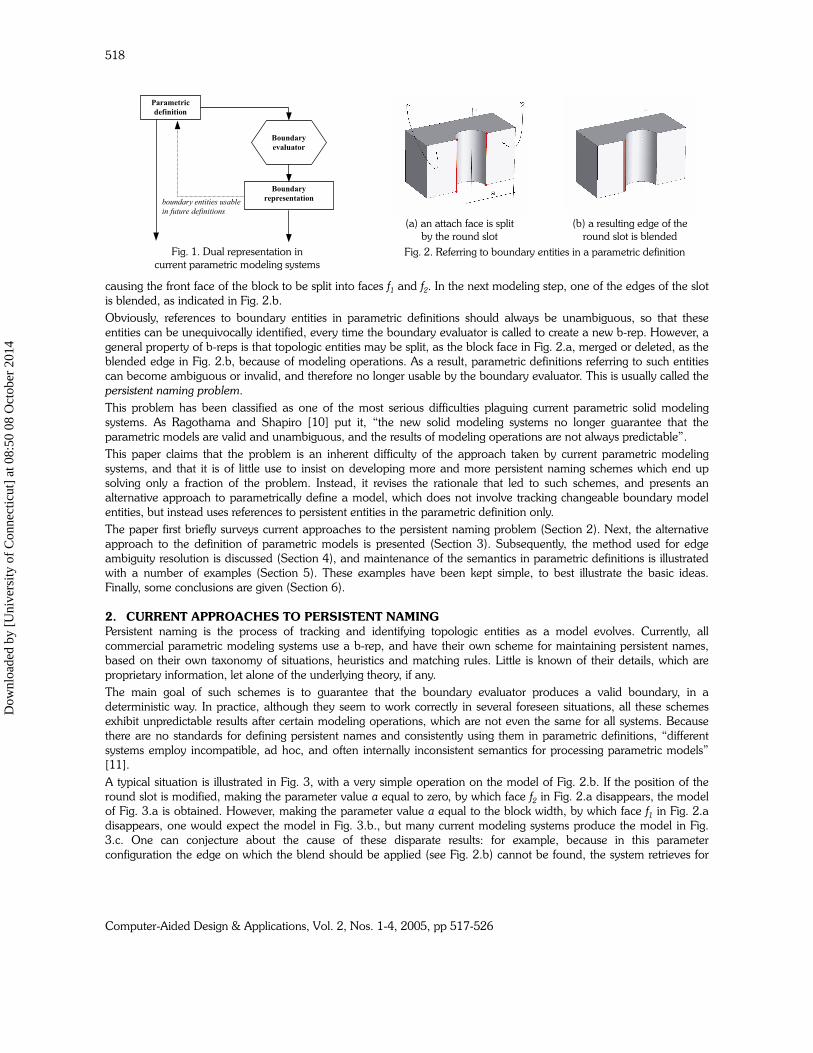
Most current modeling systems are parametric, history-based feature modeling systems using a dual representation for
solid objects: on the one hand a parametric definition of the object, on the other hand a boundary representation (b-
rep) of the resulting shape; see Fig. 1. The parametric definition can consist of a variety of information, usually
organized in a graph structure. Typically, the graph represents relations involving instances of parameterized features,
constraints, set operations, auxiliary geometric entities, etc. Among these relations, the most important is usually the
order of creation of feature instances, defining the so-called model history.
Creating a new feature instance in the model, by providing a set of input values for its parameters, appends a new
node to the model history, yielding a new parametric definition of the object. Similarly, feature instances can be
modified by specifying new values for their parameters, or be deleted from the model. This is done by modifying, or
deleting, the respective feature node in the model history. Whenever a new parametric definition is obtained, it can be
input to the boundary evaluator, which generates the corresponding new boundary representation. This can be realized
by, for example, sequentially re-executing all or a subset of the steps in the modified model history.
The ability to easily generate variants of a feature model is one of the main reasons for the popularity of current
parametric modeling systems. An important characteristic of these systems, highlighted by the loop in Fig. 1, is that
they allow the use of topologic entities (e.g. faces and edges) of the b-rep in the specification of subsequent parametric
definitions. Consequently, each node in the model history typically contains references to topologic entities of the
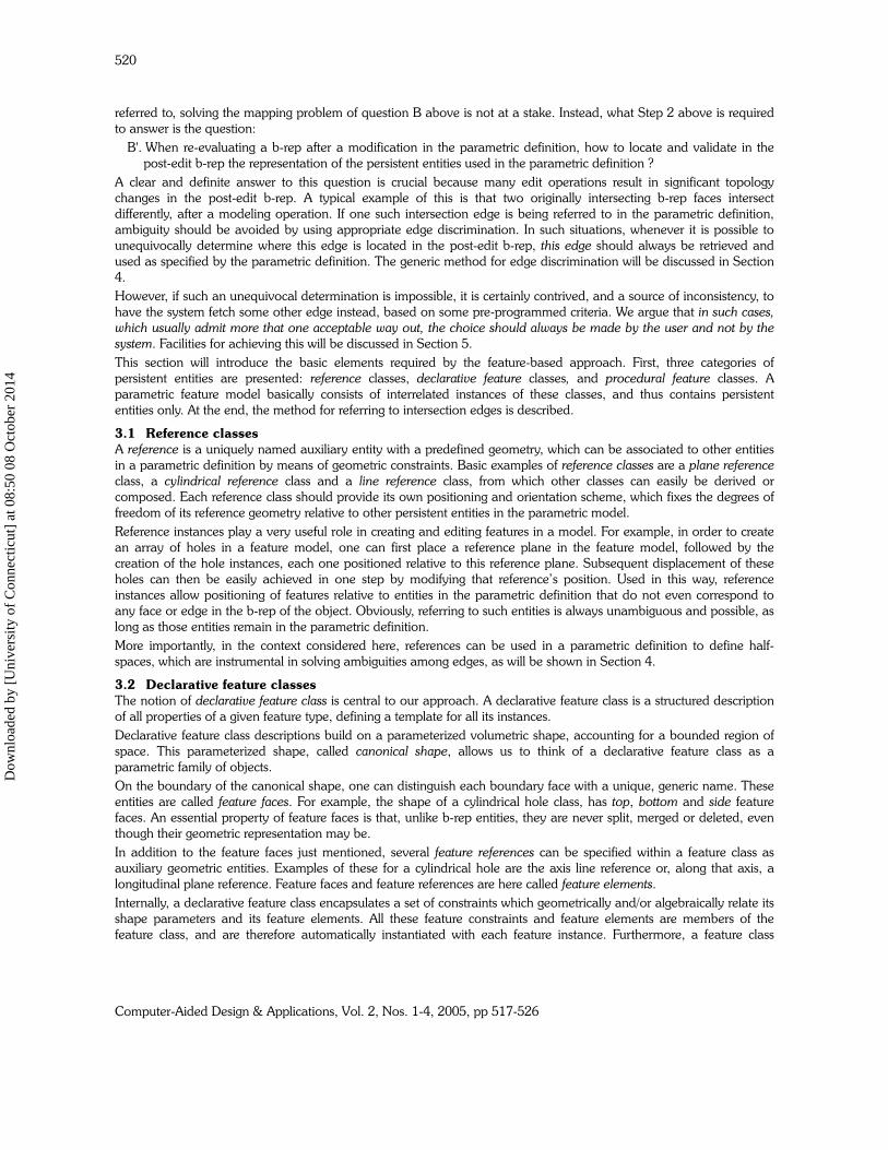
intermediate b-rep which resulted from the previous modeling step. As an example of this, the model in Fig. 2.a shows
a cylindrical through slot, attached to the front face of a block, and positioned at a distance a from its right edge,
Dow
nloa
ded
by [
Uni
vers
ity o
f C
onne
ctic
ut]
at 0
8:50
08
Oct
ober
201
4
Computer-Aided Design & Applications, Vol. 2, Nos. 1-4, 2005, pp 517-526
518
causing the front face of the block to be split into faces f1 and f2. In the next modeling step, one of the edges of the slot
is blended, as indicated in Fig. 2.b.
Obviously, references to boundary entities in parametric definitions should always be unambiguous, so that these
entities can be unequivocally identified, every time the boundary evaluator is called to create a new b-rep. However, a
general property of b-reps is that topologic entities may be split, as the block face in Fig. 2.a, merged or deleted, as the
blended edge in Fig. 2.b, because of modeling operations. As a result, parametric definitions referring to such entities
can become ambiguous or invalid, and therefore no longer usable by the boundary evaluator. This is usually called the
persistent naming problem.
This problem has been classified as one of the most serious difficulties plaguing current parametric solid modeling
systems. As Ragothama and Shapiro [10] put it, “the new solid modeling systems no longer guarantee that the
parametric models are valid and unambiguous, and the results of modeling operations are not always predictable”.
This paper claims that the problem is an inherent difficulty of the approach taken by current parametric modeling
systems, and that it is of little use to insist on developing more and more persistent naming schemes which end up
solving only a fraction of the problem. Instead, it revises the rationale that led to such schemes, and presents an
alternative approach to parametrically define a model, which does not involve tracking changeable boundary model
entities, but instead uses references to persistent entities in the parametric definition only.
The paper first briefly surveys current approaches to the persistent naming problem (Section 2). Next, the alternative
approach to the definition of parametric models is presented (Section 3). Subsequently, the method used for edge
ambiguity resolution is discussed (Section 4), and maintenance of the semantics in parametric definitions is illustrated
with a number of examples (Section 5). These examples have been kept simple, to best illustrate the basic ideas.
Finally, some conclusions are given (Section 6).
2. CURRENT APPROACHES TO PERSISTENT NAMING
Persistent naming is the process of tracking and identifying topologic entities as a model evolves. Currently, all
commercial parametric modeling systems use a b-rep, and have their own scheme for maintaining persistent names,
based on their own taxonomy of situations, heuristics and matching rules. Little is known of their details, which are
proprietary information, let alone of the underlying theory, if any.
The main goal of such schemes is to guarantee that the boundary evaluator produces a valid boundary, in a
deterministic way. In practice, although they seem to work correctly in several foreseen situations, all these schemes
exhibit unpredictable results after certain modeling operations, which are not even the same for all systems. Because
there are no standards for defining persistent names and consistently using them in parametric definitions, “different
systems employ incompatible, ad hoc, and often internally inconsistent semantics for processing parametric models”
[11].
A typical situation is illustrated in Fig. 3, with a very simple operation on the model of Fig. 2.b. If the position of the
round slot is modified, making the parameter value a equal to zero, by which face f2 in Fig. 2.a disappears, the model
of Fig. 3.a is obtained. However, making the parameter value a equal to the block width, by which face f1 in Fig. 2.a
disappears, one would expect the model in Fig. 3.b., but many current modeling systems produce the model in Fig.
3.c. One can conjecture about the cause of these disparate results: for example, because in this parameter
configuration the edge on which the blend should be applied (see Fig. 2.b) cannot be found, the system retrieves for
Parametric
definition
Boundary
representation
Boundary
evaluator
boundary entities usable
in future definitions
Fig. 1. Dual representation in
current parametric modeling systems
(a) an attach face is split
by the round slot
(b) a resulting edge of the
round slot is blended
Fig. 2. Referring to boundary entities in a parametric definition
Dow
nloa
ded
by [
Uni
vers
ity o
f C
onne
ctic
ut]
at 0
8:50
08
Oct
ober
201
4

Computer-Aided Design & Applications, Vol. 2, Nos. 1-4, 2005, pp 517-526
519
that purpose the other edge resulting from the intersection of the same two faces (block front and slot), as shown in
Fig. 3.c.
This example illustrates two major aspects of the persistent naming problem which have not always been clearly
distinguished. They can be expressed through the following questions:
A. Given a b-rep, how to name a topologic entity that one needs to refer to in a parametric definition ?
B. When re-evaluating a b-rep after a modification in the parametric definition, how to map the named entities of
the pre-edit b-rep to those of the post-edit b-rep ?
An answer to question A is required in order to blend the edge in Fig. 2.b, whereas an answer to question B is required
in order to perform the edits in Fig. 3.
Since the first proposal for persistently naming topological entities by Kripac [5, 6], also several other schemes have
been brought forward to alleviate the persistent naming problem [3, 4, 7, 12], so that the boundary re-evaluation can
at least be consistently executed. See ref. [8] for a recent survey on persistent naming schemes, containing several
more references. All these schemes use auxiliary data structures to keep track of how faces and edges evolve, but do
not really solve the problem, as explained by Raghothama and Shapiro [10], who for the first time formalized the
persistent naming problem. They introduced boundary representation deformations in their approach to the problem,
which they related to the question of how to define families of objects in parametric modeling. The main issue in the
latter is to determine which objects belong to a family, defined by a prototype model, and which objects do not.
Basically they argue that as long as a continuous boundary deformation is possible from the prototype model to the
new instance, the latter is considered to be a member of the family. However, as they also admit, continuous
deformations seem to be too restrictive, and operations like splitting and merging of model entities would have to be
dealt with, in order to allow topological changes such as the elimination of holes, but this has not been elaborated.
It can be concluded that the current approaches to persistent naming have not completely solved the problem. This is,
in fact, caused by a wrong starting point: they all try to keep track of b-rep entities that are not persistent, and this is
impossible in a truly generic way. It seems, therefore, more effective to develop a new approach, with a better starting
point.
3. THE FEATURE-BASED APPROACH
All approaches mentioned in the previous section are in one way or another tied to the generic scheme of Fig. 1. As a
result, parametric definitions are dependent on (the entities of) previously generated b-reps, while at the same time
they determine a new resulting b-rep. Since this interdependence is the real cause of the persistent naming problem,
one may legitimately wonder whether it is possible to eliminate it.
This question is affirmatively answered in this section, which presents an alternative approach to the parametric
definition of feature models. Its basic idea can be summarized as follows:
1. provide and consistently refer to persistent entities in the parametric definition domain;
2. at each boundary evaluation step, ascertain that the semantics in the parametric definition still holds.
A similar idea to Step 1 has been hinted before by Pratt [9], and has been partially elaborated in [2]. Step 2 has not
been proposed before.
The approach just sketched has the important advantage of clearly separating the two aspects of the persistent naming
problem, A and B, highlighted in the previous section. In fact, Step 1 above will allow us, within a parametric
definition, to refer to any entity of interest, whereas a successful Step 2 will guarantee that the post-edit b-rep conforms
to all semantic requirements of the parametric definition. Because in Step 1 no topologic entities of the b-rep are
(a) (b) (c)
Fig. 3. Disparity of boundary evaluation results
Dow
nloa
ded
by [
Uni
vers
ity o
f C
onne
ctic
ut]
at 0
8:50
08
Oct
ober
201
4
Computer-Aided Design & Applications, Vol. 2, Nos. 1-4, 2005, pp 517-526
520
referred to, solving the mapping problem of question B above is not at a stake. Instead, what Step 2 above is required
to answer is the question:
B'. When re-evaluating a b-rep after a modification in the parametric definition, how to locate and validate in the
post-edit b-rep the representation of the persistent entities used in the parametric definition ?
A clear and definite answer to this question is crucial because many edit operations result in significant topology
changes in the post-edit b-rep. A typical example of this is that two originally intersecting b-rep faces intersect
differently, after a modeling operation. If one such intersection edge is being referred to in the parametric definition,
ambiguity should be avoided by using appropriate edge discrimination. In such situations, whenever it is possible to
unequivocally determine where this edge is located in the post-edit b-rep, this edge should always be retrieved and
used as specified by the parametric definition. The generic method for edge discrimination will be discussed in Section
4.
However, if such an unequivocal determination is impossible, it is certainly contrived, and a source of inconsistency, to
have the system fetch some other edge instead, based on some pre-programmed criteria. We argue that in such cases,
which usually admit more that one acceptable way out, the choice should always be made by the user and not by the
system. Facilities for achieving this will be discussed in Section 5.
This section will introduce the basic elements required by the feature-based approach. First, three categories of
persistent entities are presented: reference classes, declarative feature classes, and procedural feature classes. A
parametric feature model basically consists of interrelated instances of these classes, and thus contains persistent
entities only. At the end, the method for referring to intersection edges is described.
3.1 Reference classes
A reference is a uniquely named auxiliary entity with a predefined geometry, which can be associated to other entities
in a parametric definition by means of geometric constraints. Basic examples of reference classes are a plane reference
class, a cylindrical reference class and a line reference class, from which other classes can easily be derived or
composed. Each reference class should provide its own positioning and orientation scheme, which fixes the degrees of
freedom of its reference geometry relative to other persistent entities in the parametric model.
Reference instances play a very useful role in creating and editing features in a model. For example, in order to create
an array of holes in a feature model, one can first place a reference plane in the feature model, followed by the
creation of the hole instances, each one positioned relative to this reference plane. Subsequent displacement of these
holes can then be easily achieved in one step by modifying that reference’s position. Used in this way, reference
instances allow positioning of features relative to entities in the parametric definition that do not even correspond to
any face or edge in the b-rep of the object. Obviously, referring to such entities is always unambiguous and possible, as
long as those entities remain in the parametric definition.
More importantly, in the context considered here, references can be used in a parametric definition to define half-
spaces, which are instrumental in solving ambiguities among edges, as will be shown in Section 4.
3.2 Declarative feature classes
The notion of declarative feature class is central to our approach. A declarative feature class is a structured description
of all properties of a given feature type, defining a template for all its instances.
Declarative feature class descriptions build on a parameterized volumetric shape, accounting for a bounded region of
space. This parameterized shape, called canonical shape, allows us to think of a declarative feature class as a
parametric family of objects.
On the boundary of the canonical shape, one can distinguish each boundary face with a unique, generic name. These
entities are called feature faces. For example, the shape of a cylindrical hole class, has top, bottom and side feature
faces. An essential property of feature faces is that, unlike b-rep entities, they are never split, merged or deleted, even
though their geometric representation may be.
In addition to the feature faces just mentioned, several feature references can be specified within a feature class as
auxiliary geometric entities. Examples of these for a cylindrical hole are the axis line reference or, along that axis, a
longitudinal plane reference. Feature faces and feature references are here called feature elements.
Internally, a declarative feature class encapsulates a set of constraints which geometrically and/or algebraically relate its
shape parameters and its feature elements. All these feature constraints and feature elements are members of the
feature class, and are therefore automatically instantiated with each feature instance. Furthermore, a feature class
Dow
nloa
ded
by [
Uni
vers
ity o
f C
onne
ctic
ut]
at 0
8:50
08
Oct
ober
201
4
Computer-Aided Design & Applications, Vol. 2, Nos. 1-4, 2005, pp 517-526
521
associates to its shape the notion of feature nature, indicating whether its feature instances represent material added to
or removed from the model (respectively additive and subtractive natures).
Typically, the feature elements and a number of feature shape parameters are made public in a feature class, and
belong therefore to the class interface. In addition, each feature class may specify in its interface a number of
positioning and orientation schemes, which allows us to relate some of its feature elements to external entities. The
latter can be chosen out of, for example, the feature elements of features already present in the model.
Using feature elements for attaching and positioning features relative to each other in a model has two main
advantages. First, a dependency relation is established in the parametric definition among its features. Second, each of
these elements is indeed persistent, and therefore its unique name is also persistent. Indeed, assuming no two feature
instances have equal names, which is easy to realize, the combination
<feature instance name>.<feature element name>
unequivocally determines one and only one entity, which can always be found in the parametric definition domain, as
long as that feature instance has not been explicitly removed.
In order to fully exploit the potential of the feature faces, it is necessary, in particular for their identification, that each
face in the b-rep of a feature model be always a geometric representation of (possibly a part of) one and only one
feature face. This is easily achieved by fulfilling the following two requirements: (i) every b-rep face carries an attribute
with the name of the feature face from which it originates (called its owner), and propagates this name every time it
gets split; and (ii) two adjacent b-rep faces that are coplanar are never merged, unless they have the same owner.
Although the latter is in contrast to common b-reps based on maximal faces, this requirement poses no limitations
regarding efficiency, model traversal, model visualization or face selection.
The above property is very important for user interaction purposes, e.g. at the moment of picking some b-rep face on
the visualized model, in order to attach or position a feature: it is always possible to find out which corresponding
feature face should be stored in the parametric definition for that operation.
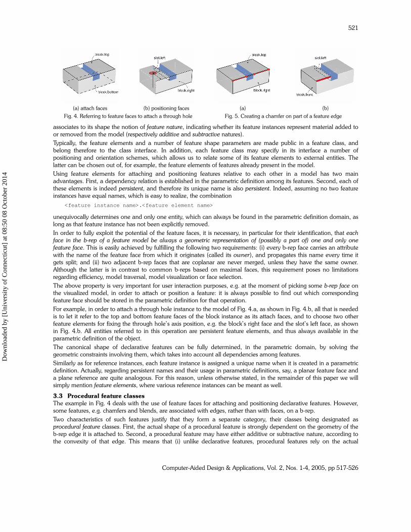
For example, in order to attach a through hole instance to the model of Fig. 4.a, as shown in Fig. 4.b, all that is needed
is to let it refer to the top and bottom feature faces of the block instance as its attach faces, and to choose two other
feature elements for fixing the through hole’s axis position, e.g. the block’s right face and the slot’s left face, as shown
in Fig. 4.b. All entities referred to in this operation are persistent feature elements, and thus always available in the
parametric definition of the object.
The canonical shape of declarative features can be fully determined, in the parametric domain, by solving the
geometric constraints involving them, which takes into account all dependencies among features.
Similarly as for reference instances, each feature instance is assigned a unique name when it is created in a parametric
definition. Actually, regarding persistent names and their usage in parametric definitions, say, a planar feature face and
a plane reference are quite analogous. For this reason, unless otherwise stated, in the remainder of this paper we will
simply mention feature elements, where various reference instances can be meant as well.
3.3 Procedural feature classes
The example in Fig. 4 deals with the use of feature faces for attaching and positioning declarative features. However,
some features, e.g. chamfers and blends, are associated with edges, rather than with faces, on a b-rep.
Two characteristics of such features justify that they form a separate category, their classes being designated as
procedural feature classes. First, the actual shape of a procedural feature is strongly dependent on the geometry of the
b-rep edge it is attached to. Second, a procedural feature may have either additive or subtractive nature, according to
the convexity of that edge. This means that (i) unlike declarative features, procedural features rely on the actual
(a) attach faces (b) positioning faces
Fig. 4. Referring to feature faces to attach a through hole
(a) (b)
Fig. 5. Creating a chamfer on part of a feature edge
Dow
nloa
ded
by [
Uni
vers
ity o
f C
onne
ctic
ut]
at 0
8:50
08
Oct
ober
201
4
Computer-Aided Design & Applications, Vol. 2, Nos. 1-4, 2005, pp 517-526
522
existence of a particular edge on the b-rep, and (ii) their shape can only be determined after that edge has been
identified and located.
In other words, the semantics of a procedural feature is such that, whereas on the one hand it poses specific
requirements on the evaluated b-rep (e.g. the edge must exist and be unambiguously identified), on the other hand
that same semantics is configured by the evaluated b-rep (e.g. by the particular geometry or convexity of the edge).
The difficulties raised by this necessity of referring to an edge from within the parametric definition of procedural
features will be dealt with in the next subsection.
3.4 Referring to edges
Referring to b-rep edges presents the most challenging problems in all persistent naming approaches. Among other
reasons, b-rep edges are strongly dependent on the particular way in which features intersect: a small parameter
variation can have drastic consequences on the topology of the boundary model.
In order to characterize b-rep edges, one should first realize that for every edge in a manifold b-rep consisting of planar
faces holds that it has always two adjacent b-rep faces. Similarly, regarding the start and end vertices of any edge, one
can also observe that there is always an additional face incident on each vertex.
In turn, because each of these four b-rep faces is always representing some feature face, referring to a b-rep edge can
again be transferred to the parametric definition domain, involving references to the corresponding feature faces.
Indeed, these two pairs of feature faces are enough to unequivocally determine an edge, as illustrated by the example
in Fig. 5, where a chamfer is to be applied on an edge. Although in this model two b-rep edges lie at the intersection of
the feature faces block.top and block.right (Fig. 5.a), the desired edge can be distinguished by indicating one other
feature face incident on its start vertex and one on its end vertex (Fig. 5.b). In other words, the pair
(<block.top,block.right>, <block.front,slot.left>)
can be used to identify that edge in the parametric definition of the chamfer.
Assuming that each b-rep face carries an attribute with the corresponding feature face name (see Subsection 3.2), it is
always possible to search the b-rep for an edge having the feature face adjacency relations specified by a pair in the
form:
(<adjacent feature faces>, <discriminator>)
In the example of Fig. 5, the discriminator consists of the names of the start and end feature faces. These two feature
faces names are always able to discriminate any edge resulting from the intersection of two planar feature faces.
However, such discriminators are not always sufficient to unambiguously identify intersection edges defined by non-
planar faces, as illustrated by the example in Fig. 2.a, where a 'feature face' of the block intersects twice the cylindrical
'feature face' of the round slot, and both intersection edges have the same feature faces incident on their start and end
vertices.
It is in such situations that it becomes necessary to further discriminate those edges. We use half-spaces, defined by
means of references, to disambiguate multiple intersection edges using only vocabulary from the parametric definition
domain, as will be described in the next section.
4. EDGE AMBIGUITY RESOLUTION THROUGH AUTOMATIC HALF-SPACE PARTITIONING
The basic idea of our method for disambiguation of multiple intersection edges between two intersecting faces consists
of automatically defining (one or more pairs of) half-spaces such that no two edges lie in the same (combination of)
half-space(s). Each pair of half-spaces is defined by a reference instance that is automatically positioned relative to
(entities of) the two features whose faces are intersecting. Depending on the geometry of the intersecting faces and/or
on the number of intersection edges, one or more pairs of half-spaces may be required to achieve a complete edge
discrimination.
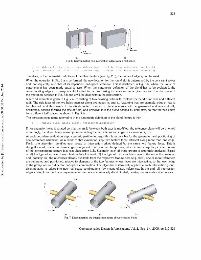
The procedure can be illustrated with the example of Figures 2 and 3. When the edge to be blended is selected, its two
adjacent feature faces –block.front and slot.side– are analyzed. Because one of them is cylindrical, and two edges arise
from their intersection (see Fig. 6.a), a plane reference is generated automatically and positioned relative to the two
intersecting faces: passing through the axis of the cylindrical face (of the slot) and orthogonal to the planar face (of the
block). As a result, the two intersection edges can be distinguished, in the parametric definition domain, by means of
their half-space discriminator, using the following persistent names:
Dow
nloa
ded
by [
Uni
vers
ity o
f C
onne
ctic
ut]
at 0
8:50
08
Oct
ober
201
4
Computer-Aided Design & Applications, Vol. 2, Nos. 1-4, 2005, pp 517-526
523
e1 → (<block.front, slot.side>, <block.top, block.bottom, reference.positive>)
e2 → (<block.front, slot.side>, <block.top, block.bottom, reference.negative>)
Therefore, in the parametric definition of the blend feature (see Fig. 2.b), the name of edge e1 can be used.
When the operation in Fig. 3.a is performed, the new location for the round slot is determined by the constraint solver
and, consequently, also that of its dependent half-space reference. This is illustrated in Fig. 6.b, where the value of
parameter a has been made equal to zero. When the parametric definition of the blend has to be evaluated, the
corresponding edge e1 is unequivocally located in the b-rep using its persistent name given above. The discussion of
the operation depicted in Fig. 3.b and c will be dealt with in the next section.
A second example is given in Fig. 7.a, consisting of two crossing holes with coplanar perpendicular axes and different
radii. The side faces of the two holes intersect along two edges, e1 and e2. Assuming that, for example, edge e1 has to
be blended, and thus needs to be discriminated from e2, a plane reference will be generated and automatically
positioned, passing through the axis of hole1 and orthogonal to the plane defined by both axes, so that the two edges
lie in different half-spaces, as shown in Fig. 7.b.
The persistent edge name referred to in the parametric definition of the blend feature is then
e1 → (<hole1.side, hole2.side>, <reference.negative>)
If, for example, hole1 is rotated so that the angle between both axes is modified, the reference plane will be oriented
accordingly, therefore always correctly discriminating the two intersection edges, as shown in Fig. 7.c.
At each boundary evaluation step, a generic partitioning algorithm is responsible for the generation and positioning of
new references whenever, as a result of that evaluation step, two feature faces intersect along more than one edge.
Firstly, the algorithm identifies each group of intersection edges defined by the same two feature faces. This is
straightforward, as each of those edges is adjacent to at most two b-rep faces, which in turn carry the persistent name
of the corresponding feature face (see Subsection 3.2). Secondly, each of these groups is separately analyzed. Based
on (i) the type of surface of each feature face involved, (ii) the type of the canonical shape in the respective features,
and, possibly, (iii) the references already available from the respective feature class (e.g. axes), one or more references
are generated and positioned, relative to elements of the two features whose faces are intersecting, so that each edge
in the group falls in a different half-space combination. The algorithm is iteratively applied to each intersection group,
discriminating its edges into new half-space combinations, by means of new references. In the end, all intersection
edges arising from that boundary evaluation step are unequivocally discriminated, bearing names as described above.
(a) (b)
Fig. 6. Discriminating two intersection edges with a half-space
(a) (b) (c)
Fig. 7. Discriminating the intersection edges of two crossing holes
Dow
nloa
ded
by [
Uni
vers
ity o
f C
onne
ctic
ut]
at 0
8:50
08
Oct
ober
201
4
Computer-Aided Design & Applications, Vol. 2, Nos. 1-4, 2005, pp 517-526
524
The disambiguating method just proposed has been successfully validated for the domain of faces with quadric
surfaces (planar, cylindrical, spherical and toroidal). It has the obvious advantage that it consistently refers to persistent
entities only, either feature faces or references. The method guarantees that, whenever the b-rep has to be re-
evaluated, the names of these persistent entities can be used to unequivocally identify the corresponding b-rep entity. If
the latter is indeed present in the b-rep, it is retrieved and used as required by the parametric definition being
processed. If, however, that entity cannot be unequivocally found in the b-rep, we have an essentially different
situation. The detection and handling of such cases is the subject of the next section.
5. PRESERVING SEMANTICS IN PARAMETRIC DEFINITIONS
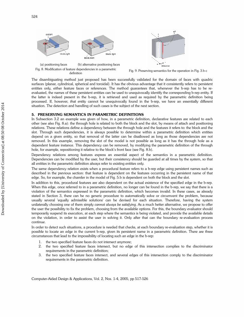
In Subsection 3.2 an example was given of how, in a parametric definition, declarative features are related to each
other (see also Fig. 8.a): the through hole is related to both the block and the slot, by means of attach and positioning
relations. These relations define a dependency between the through hole and the features it refers to: the block and the
slot. Through such dependencies, it is always possible to determine within a parametric definition which entities
depend on a given entity, so that removal of the latter can be disallowed as long as those dependencies are not
removed. In this example, removing the slot of the model is not possible as long as it has the through hole as a
dependent feature instance. This dependency can be removed, by modifying the parametric definition of the through
hole, for example, repositioning it relative to the block’s front face (see Fig. 8.b).
Dependency relations among features express an essential aspect of the semantics in a parametric definition.
Dependencies can be modified by the user, but their consistency should be guarded at all times by the system, so that
all entities in the parametric definition always refer to existing entities only.
The same dependency relation exists when a procedural feature refers to a b-rep edge using persistent names such as
described in the previous section: that feature is dependent on the features occurring in the persistent name of that
edge. So, for example, the chamfer in the model of Fig. 5.b is dependent on both the block and the slot.
In addition to this, procedural features are also dependent on the actual existence of the specified edge in the b-rep.
When this edge, once referred to in a parametric definition, no longer can be found in the b-rep, we say that there is a
violation of the semantics expressed in the parametric definition, which becomes invalid. In these cases, as already
stated in Section 3, there can be no generic procedure to automatically solve or circumvent the problem, because
usually several 'equally admissible solutions' can be devised for each situation. Therefore, having the system
unilaterally choosing one of them simply cannot always be satisfying. As a much better alternative, we propose to offer
the user the possibility to fix the problem, choosing from the available options. For this, the boundary evaluator should
temporarily suspend its execution, at each step where the semantics is being violated, and provide the available details
on the violation, in order to assist the user in solving it. Only after that can the boundary re-evaluation process
continue.
In order to detect such situations, a procedure is needed that checks, at each boundary re-evaluation step, whether it is
possible to locate an edge in the current b-rep, given its persistent name in a parametric definition. There are three
circumstances that lead to the impossibility of locating such an edge in the b-rep:
1. the two specified feature faces do not intersect anymore;
2. the two specified feature faces intersect, but no edge of this intersection complies to the discriminator
requirements in the parametric definition;
3. the two specified feature faces intersect, and several edges of this intersection comply to the discriminator
requirements in the parametric definition.
(a) positioning faces
(b) alternative positioning faces
Fig. 8. Modification of feature dependencies in a parametric
definition
Fig. 9. Preserving semantics for the operation in Fig. 3.b-c
Dow
nloa
ded
by [
Uni
vers
ity o
f C
onne
ctic
ut]
at 0
8:50
08
Oct
ober
201
4
Computer-Aided Design & Applications, Vol. 2, Nos. 1-4, 2005, pp 517-526
525
The first case is trivial, and can easily be detected by observing that no edge in the b-rep has as adjacent faces the two
feature faces specified in the given persistent name.
For the other cases, the b-rep is also searched and all intersection edges defined by the two specified feature faces are
retrieved. For each such edge, a check is performed on whether it complies to the discriminator requirements.
A simple example of Case 2 above is related to the operation in Fig. 3.b-c. Assume that the discriminator for the
blended edge is that given in the previous section (see again Fig. 6.a). When the round slot, together with its
dependent reference, is displaced to the left, as shown in Fig. 9, then there remains only one intersection edge between
the block.front and the slot.side faces, but this edge is located in the half-space opposite to the one specified in the
discriminator. Consequently, regarding the specification of the blend feature, its required edge does not exist anymore
and the parametric definition becomes invalid.
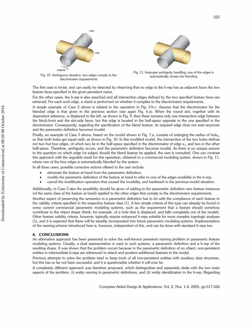
Finally, an example of Case 3 above, based on the model shown in Fig. 7.a, consists of enlarging the radius of hole2,
so that both holes get equal radii, as shown in Fig. 10. In this modified model, the intersection of the two holes defines
not two but four edges, of which two lie in the half-space specified in the discriminator of edge e1, and two in the other
half-space. Therefore, ambiguity occurs, and the parametric definition becomes invalid. As there is no unique answer
to the question on which edge (or edges) should the blend feature be applied, the user is consulted. One can contrast
this approach with the arguable result for this operation, obtained in a commercial modeling system, shown in Fig. 11,
where one of the four edges is automatically blended by the system.
In all three cases, possible corrective actions offered to the user include:
• eliminate the feature at hand from the parametric definition;
• modify the parametric definition of the feature at hand to refer to one of the edges available in the b-rep;
• cancel the modification operation that caused the invalidity, and backtrack to the previous model situation.
Additionally, in Case 3 also the possibility should be given of adding to the parametric definition new feature instances
(of the same class of the feature at hand) applied to the other edges that comply to the discriminator requirements.
Another aspect of preserving the semantics in a parametric definition has to do with the compliance of each feature to
the validity criteria specified in the respective feature class [1]. A few simple criteria of this type can already be found in
some current commercial parametric modeling systems, such as the requirement that a feature should somehow
contribute to the object shape (think, for example, of a hole that is displaced, and falls completely out of the model).
Other feature validity criteria, however, typically require enhanced b-reps suitable for more complex topologic analyses
[1], and it is expected that these will be steadily incorporated into future parametric modeling systems. Implementation
of the naming scheme introduced here is, however, independent of this, and can be done with standard b-reps too.
6. CONCLUSIONS
An alternative approach has been presented to solve the well-known persistent naming problem in parametric feature
modeling systems. Usually, a dual representation is used in such systems: a parametric definition and a b-rep of the
resulting shape. It was shown that the problem occurs because in the parametric definition of an object, non-persistent
entities in intermediate b-reps are referenced to attach and position additional features in the model.
Previous attempts to solve the problem tried to keep track of all non-persistent entities with auxiliary data structures,
but this has so far not been successful, and it is questionable whether it will ever be.
A completely different approach was therefore proposed, which distinguishes and separately deals with the two main
aspects of the problem: (i) entity naming in parametric definitions, and (ii) entity identification in the b-rep. Regarding
Fig. 10. Ambiguous situation: two edges comply to the
discriminator requirements
Fig. 11. Improper ambiguity handling: one of the edges is
automatically chosen for blending
Dow
nloa
ded
by [
Uni
vers
ity o
f C
onne
ctic
ut]
at 0
8:50
08
Oct
ober
201
4
Computer-Aided Design & Applications, Vol. 2, Nos. 1-4, 2005, pp 517-526
526
the former, all references are made to entities in the parametric definition, instead of in the b-rep. Such entities are
persistent and so, obviously, their names too. Regarding the latter, feature-related information is deployed, both in the
parametric definition and in the b-rep, to identify any entity being referred to.
One might say that in this way the persistent naming problem, at least in its original formulation, was actually avoided.
However, in fact, this feature-based approach deals with unambiguous cases in a straightforward way, and with
ambiguous cases in a realistic way: refraining from attempting to automatically manage them, because of their intrinsic
ambivalence, but, instead, requesting user intervention in order to choose out of the available solutions.
The feature-based approach has been illustrated with several examples, and contrasted with results for the same
operations obtained using current commercial modeling systems. Notably, the solution proposed poses no special
requirements on the boundary representation used, and may therefore be used in any parametric modeling system, as
long as there is a clear separation between the parametric definition and the representation of the resulting shape. It
may, therefore, contribute to the solution of a long-lasting problem in parametric feature modeling.
REFERENCES
[1] Bidarra, R. and Bronsvoort, W.F. (2000) Semantic feature modelling. Computer Aided-Design 32(3): 201–225
[2] Bidarra, R. and Bronsvoort, W.F. (2002) Persistent naming through persistent entities. In: Proceedings of
Geometric Modeling and Processing 2002 - Theory and Applications, 10–12 July, Wako, Japan, Suzuki, H. and
Martin, R. (Eds.), IEEE Computer Society, CA, pp. 233–240
[3] Capoyleas, V., Chen, X. and Hoffmann, C.M. (1996) Generic naming in generative, constraint-based design.
Computer-Aided Design 28(1): 17–26
[4] Chen, X. and Hoffmann, C.M. (1995) On editability of feature-based design. Computer-Aided Design 27(12):
905–914
[5] Kripac, J., (1994) Topological ID System — A mechanism for persistently naming topological entities in history-
based parametric solid models. PhD Thesis, Czech Technical University, School of Electrical Engineering,
Department of Computer Science, Czech Republic, Prague, 1994
[6] Kripac, J. (1995) A mechanism for persistently naming topological entities in history-based parametric solid
models. In: Proceedings of Solid Modeling ‘95 – Third Symposium on Solid Modeling and Applications, 17–19
May, Salt Lake City, UT, USA, Hoffmann, C.M. and Rossignac, J.R. (Eds.), ACM Press, New York, pp. 21–30.
Also in: Computer-Aided Design 29(2): 113–122
[7] Lequette, R. (1997) Considerations on topological naming. In: Product Modeling for Computer Integrated
Design and Manufacturing – Proceedings of IFIP TC5/WG5.2 International Workshop on Geometric Modeling in
Computer Aided Design, 19–23 May 1996, Airlie, VA, USA, Pratt, M., Sriram, R.D. and Wozny, M.J. (Eds.),
Chapman & Hall, London, pp. 394–403
[8] Marcheix, D. and Pierra, G. (2002) A survey of the persistent naming problem. In: Proceedings of Solid
Modeling ‘02 – Seventh Symposium on Solid Modeling and Applications, 17–21 June, Saarbrücken, Germany,
Lee, K. and Patrikalakis, N.M. (Eds.)
[9] Pratt, M.J. (1988) Synthesis of an optimal approach to form feature modelling. In: Proceedings of the 1988
ASME Computers in Engineering Conference, August, San Francisco, CA, USA, ASME, New York, Vol. 1, pp.
263–274
[10] Raghothama, S. and Shapiro, V. (1998) Boundary representation deformation in parametric solid modeling.
ACM Transactions on Graphics 17(4): 259–286
[11] Shapiro, V. and Vossler, D.L. (1995) What is a parametric family of solids? In: Proceedings of Solid Modeling
‘95 – Third Symposium on Solid Modeling and Applications, 17–19 May, Salt Lake City, UT, USA, Hoffmann,
C.M. and Rossignac, J.R. (Eds.), ACM Press, New York, pp. 43–54
[12] Wu, J., Zhang, T., Zhang, X. and Zhou, J. (2001) A face based mechanism for naming, recording and retrieving
topological entities. Computer-Aided Design 33(2001): 687–698
Dow
nloa
ded
by [
Uni
vers
ity o
f C
onne
ctic
ut]
at 0
8:50
08
Oct
ober
201
4