Embed Size (px)
Citation preview
A finite element model of vehicle - cable stayed bridge interaction considering braking and acceleration
*Toan Xuan Nguyen1), Duc Van Tran2)
1)Dept. of bridge and road, Danang University of Science and Technology, The
University of Danang city, Danang city, Vietnam 2) International school, Duytan University, Danang city, Vietnam
1) [email protected], 2)[email protected]
ABSTRACT
A finite element method (FEM) for the calculation of dynamic response and loading of cable-stayed bridge due to vehicle braking loads is described. The analysis takes account of vehicle acceleration or braking and eccentric placement of the vehicle on the bridge. The analysis was presented for a three-axle dumper truck vehicle and the cable-stayed bridge which was modeled as Bernoulli–Euler beam with uniform cross-section on linear spring supports and cables. The vehicle was modeled as a group of moving loads at a fixed spacing. An assumption of the averaged vehicle acceleration at current time is known. Subsequently, absolute vehicle displacements can be changed to relative vehicle displacements. Thus, the inertia force at the center of each vehicle mass can be generated. An experimental test was performed on a reality three spans cable-stayed bridge with double I steel-section beams subjected to vehicular braking load in order to test the performance of this investigation. Since braking in first span would create response in another spans, a more accurate definition of impact factor with vehicle braking based on a ratio of the maximum dynamic and static responses at the same station of span in which braking occurs. The main contribution of this paper is to validate the FEM results with the experimental results.
1. INTRODUCTION
The initial researchers had studied the response of bridges subjected to vehicles moving since the 50s of the 19th century. Recently, the study analyzed the complex problem of oscillations with the model interaction between vehicle and bridge closer to reality. Most studies focusing on the dynamic behavior of bridge subjected to vehicles moving with constant speed. Only a few research directions towards the dynamic behavior of bridge under the effect of vehicle with variable velocity (due to many reasons such as brakes, incident on the bridge ...). As Fryba (1974) introduced a fundamental study of beam due to mass roll on the train rails considering the braking force effect, and also studied the quasi-static distribution of braking. Then the study of Kishan and Trail-Nash (1977) concerned the dynamic response of highway bridges
1) Professor 2) Phd candidate
under the effect of vehicle braking force, and the resulting impact factors may larger than those adopted in the current design code. Gupta and Trail-Nash (1980) investigated the dynamic behavior of bridge model with single span uniform beam considering the road surface irregularities and vehicle braking force. Mulcahy carried out method for analysis of dynamic interaction between single span bridges and a three-axle tractor trailer vehicle considering vehicle acceleration or braking and roughness of the road surface. Krylov (1996) investigated the vibration of the ground under effect of vehicle with a constant acceleration from the rest to a constant speed. Toth and Ruge (2001) analyzed the longitudinal behavior of the railway bridge considering the braking force of the train. Yang and Wu (2001) applied and developed numerical method to investigate the dynamic behavior of a bridge when vehicle was decelerating. Hu and Han (2003) presented the non-linear behavior with four-axle vehicle model considering the braking force. Law and Zhu (2005) studied the dynamic behavior of continuous three spans under moving vehicle considering braking load and the roughness of the road surface. Ju and Lin (2007) used FEM to calculate the vertical vibration of beams caused moving vehicle due to the braking force. Toan and Duc (2007, 2011, 2012, 2014) studied the dynamic vibration of a beam subjected to moving vehicles considering the braking forces and the variable acceleration.
This study develops the FEM to analyze the interaction between three-axle dumper truck vehicle and three-span cable-stayed bridge considering the braking force and acceleration. In addition, this research evaluates the effects of the beam on vertical direction when the vehicle brakes. The moving vehicle modeled by four masses, including the mass m, m1, m2, m3, rotational inertia J of the chassis, the damping and stiffness of the suspension, spring and tires. Bridge structure is analysis as finite elements bending beams hanging on the cables subjected to direct effect of the vehicle loads. Numerical analysis results have been compared with the experimental testing results performed on PhoNam cable-stayed bridge in Danang city.
2. COMPUTATIONAL MODELS AND ASSUMPTIONS
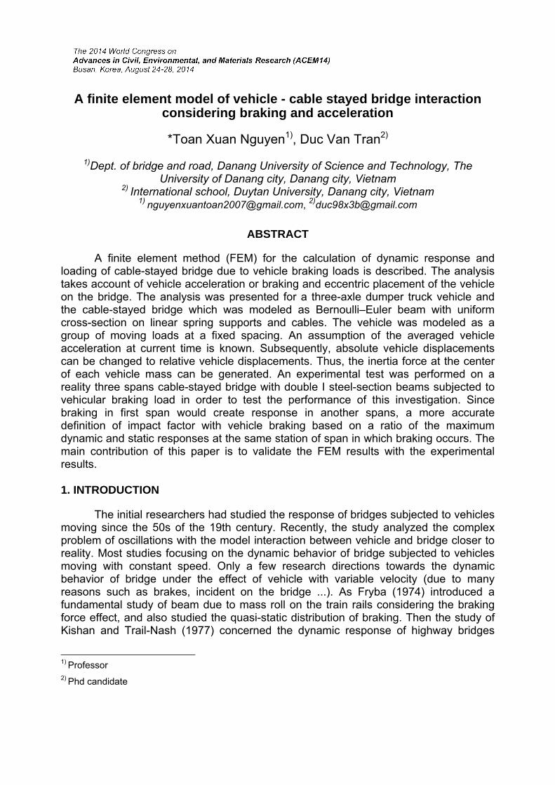
The cable-stayed bridge used in this study is the PhoNam Bridge located in Danang, Vietnam which is three span continuous cable-stayed bridge with main span is 80m; side span is 35.7m; and bridge length is 151.4m. The three-axle vehicle moving on bridge is shown on Fig. 1
80m35.7m 35.7m
O
xelf L
21.6
8m
Fig. 1 The three-axle vehicle move on the the PhoNam Bridge
The structures of cable-stayed bridge were modeled by following elements: Stayed cables were modeled as cable elements with considering tensional force
and deflection of the cables. The non-linear dynamic vibration of cable element in the cable-stayed bridges subjected to moving loads can be found in investigation of Raid K. (1999), Toan (2007).
The tower structures of the cable-stayed bridge were modeled as frame
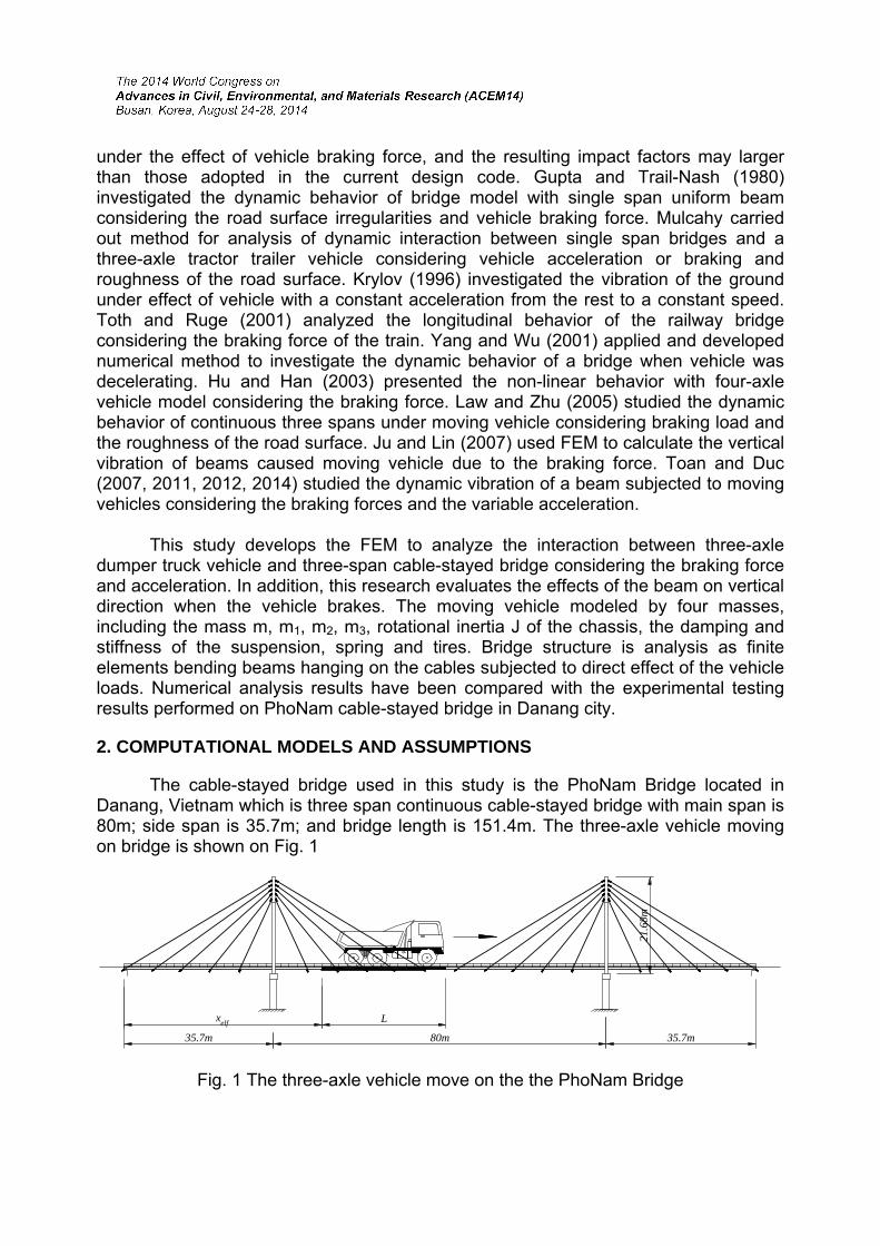
elements which can be found in Zienkiewicz (2000). The girder beams of the cable-stayed bridge were modeled as beam elements
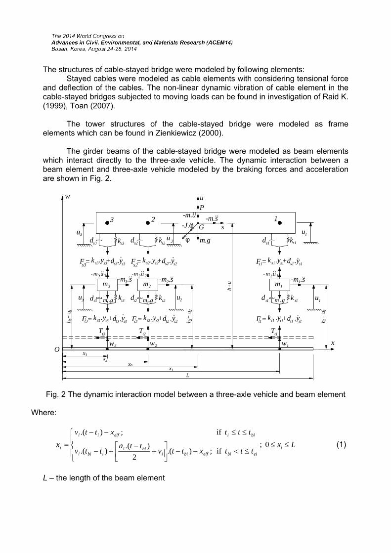
which interact directly to the three-axle vehicle. The dynamic interaction between a beam element and three-axle vehicle modeled by the braking forces and acceleration are shown in Fig. 2.
1G s
-m.s..
Pu
m.g
23-J.
m3
dt3 kt3u3
-m .s..
ds3 ks3
Fs3= ks3.ys3 ds3.ys3+.
3
Tt3
w3
h +
u3
h+um2
dt2 kt2
-m .s..
s2 s2
.
2
Tt2
w2
h +
u2
u2
m1
dt1 k t1
-m .s..
1
Tt1
w1
h +
u
u1
x
1
d k s1 s1d k13
Fs2= ks2.ys2 ds2.ys2+.
Fs1= ks1.ys1 ds1.ys1+
Ft3= kt3 .yt3 dt3 .yt3+. .
Ft2= kt2 .yt2 dt2 .yt2+.
Ft1= kt1 .yt1 dt1 .yt1+
w
Lx1
xo
x2
x3O
-m.u
m .g1 m .g2 m .g1
m .u3..
3 m .u2..
2 m .u1..
1
..
u2
- - -
..
23 1
u u
Fig. 2 The dynamic interaction model between a three-axle vehicle and beam element
Where:
eibielfbii
biiibii
biielfii
itttxttv
ttattv
tttxttv
xif ;).(
2
).().(
if ;).(
; Lxi 0 (1)
L – the length of the beam element
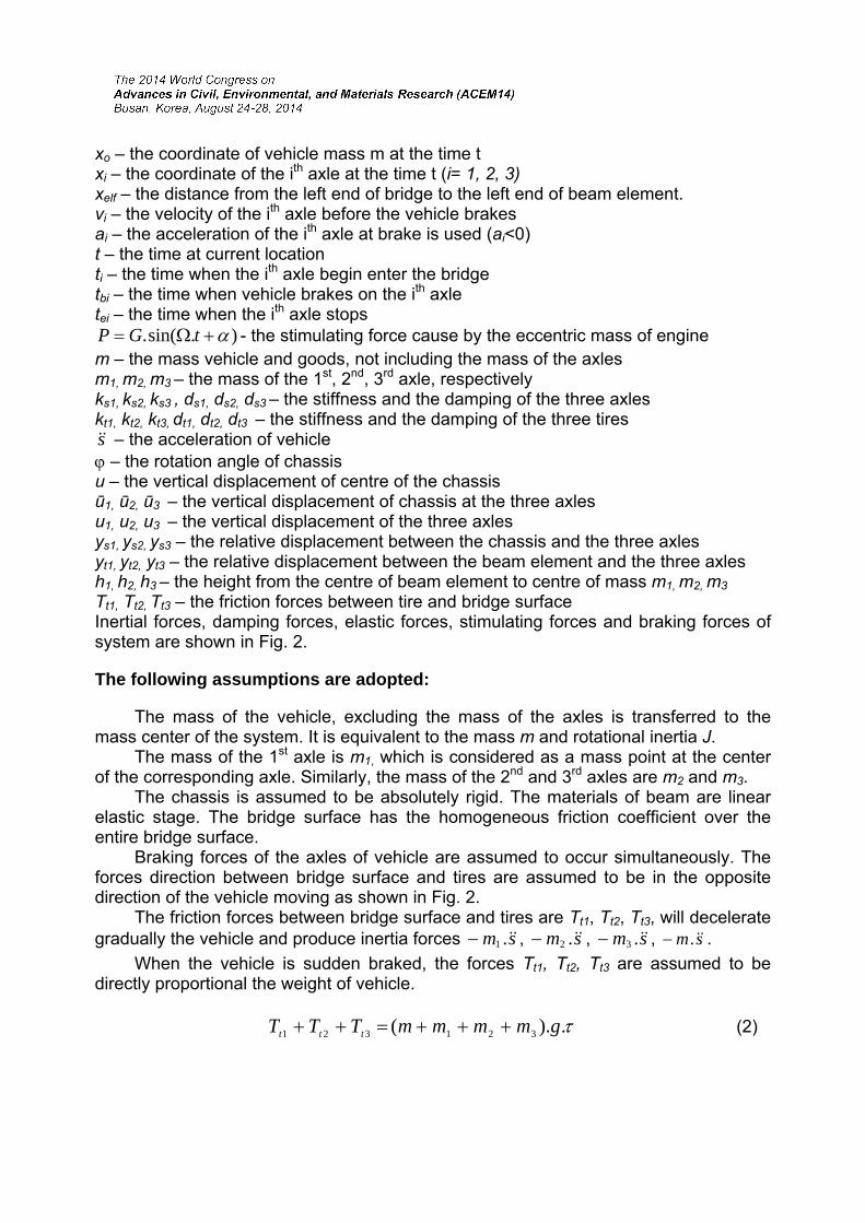
xo – the coordinate of vehicle mass m at the time t xi – the coordinate of the ith axle at the time t (i= 1, 2, 3) xelf – the distance from the left end of bridge to the left end of beam element. vi – the velocity of the ith axle before the vehicle brakes ai – the acceleration of the ith axle at brake is used (ai<0) t – the time at current location ti – the time when the ith axle begin enter the bridge tbi – the time when vehicle brakes on the ith axle tei – the time when the ith axle stops
).sin(. tGP - the stimulating force cause by the eccentric mass of engine m – the mass vehicle and goods, not including the mass of the axles m1, m2, m3 – the mass of the 1st, 2nd, 3rd axle, respectively ks1, ks2, ks3 , ds1, ds2, ds3 – the stiffness and the damping of the three axles kt1, kt2, kt3, dt1, dt2, dt3 – the stiffness and the damping of the three tires s – the acceleration of vehicle – the rotation angle of chassis u – the vertical displacement of centre of the chassis ū1, ū2, ū3 – the vertical displacement of chassis at the three axles u1, u2, u3 – the vertical displacement of the three axles ys1, ys2, ys3 – the relative displacement between the chassis and the three axles yt1, yt2, yt3 – the relative displacement between the beam element and the three axles h1, h2, h3 – the height from the centre of beam element to centre of mass m1, m2, m3 Tt1, Tt2, Tt3 – the friction forces between tire and bridge surface Inertial forces, damping forces, elastic forces, stimulating forces and braking forces of system are shown in Fig. 2.
The following assumptions are adopted:
The mass of the vehicle, excluding the mass of the axles is transferred to the mass center of the system. It is equivalent to the mass m and rotational inertia J. The mass of the 1st axle is m1, which is considered as a mass point at the center of the corresponding axle. Similarly, the mass of the 2nd and 3rd axles are m2 and m3. The chassis is assumed to be absolutely rigid. The materials of beam are linear elastic stage. The bridge surface has the homogeneous friction coefficient over the entire bridge surface. Braking forces of the axles of vehicle are assumed to occur simultaneously. The forces direction between bridge surface and tires are assumed to be in the opposite direction of the vehicle moving as shown in Fig. 2. The friction forces between bridge surface and tires are Tt1, Tt2, Tt3, will decelerate gradually the vehicle and produce inertia forces sm .1 , sm .2 , sm .3 , sm . .
When the vehicle is sudden braked, the forces Tt1, Tt2, Tt3 are assumed to be directly proportional the weight of vehicle.
.).( 321321 gmmmmTTT ttt (2)
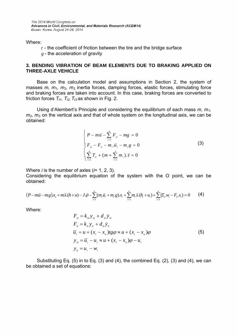
Where: - the coefficient of friction between the tire and the bridge surface g - the acceleration of gravity
3. BENDING VIBRATION OF BEAM ELEMENTS DUE TO BRAKING APPLIED ON THREE-AXLE VEHICLE Base on the calculation model and assumptions in Section 2, the system of masses m, m1, m2, m3, inertia forces, damping forces, elastic forces, stimulating force and braking forces are taken into account. In this case, braking forces are converted to friction forces Tt1, Tt2, Tt3 as shown in Fig. 2. Using d’Alembert’s Principle and considering the equilibrium of each mass m, m1, m2, m3 on the vertical axis and that of whole system on the longitudinal axis, we can be obtained:
0.)(
0.
0
11
1
smmT
gmumFF
mgFumP
n
ii
n
iti
iiitisi
n
isi
(3)
Where i is the number of axles (i= 1, 2, 3). Considering the equilibrium equation of the system with the O point, we can be obtained:
0)..().(.)...(.).(....111
itiiti
n
i
n
iiii
n
iiiiio xFwTuhsmxgmumJuhsmxgmumP (4)
Where:
iiti
ioiiisi
oioii
tititititi
sisisisisi
wuy
uxxuuuy
xxutgxxuu
ydykF
ydykF
)(
)()(
(5)
Substituting Eq. (5) in to Eq. (3) and (4), the combined Eq. (2), (3) and (4), we can be obtained a set of equations:
.
0...).(
.).().(.).(.
0....)(...)(.
0)...(.]..)([]..)([
.)().(.)(.)(.
111111
1111
1
2
111
2
gs
gmwkwdukk
ukxxkuddudxxdum
gmPukukxxkududxxdum
shmhmwTusmxxkusmxxk
xxkuxxduxxdxxdJ
iitiitiitisi
sioisiitisisioisiii
n
iisi
n
isi
n
ioisi
n
iisi
n
isi
n
ioisi
n
iii
n
iitii
n
iioisi
n
ioisi
n
ioisii
n
ioisi
n
ioisi
n
ioisi
(6)
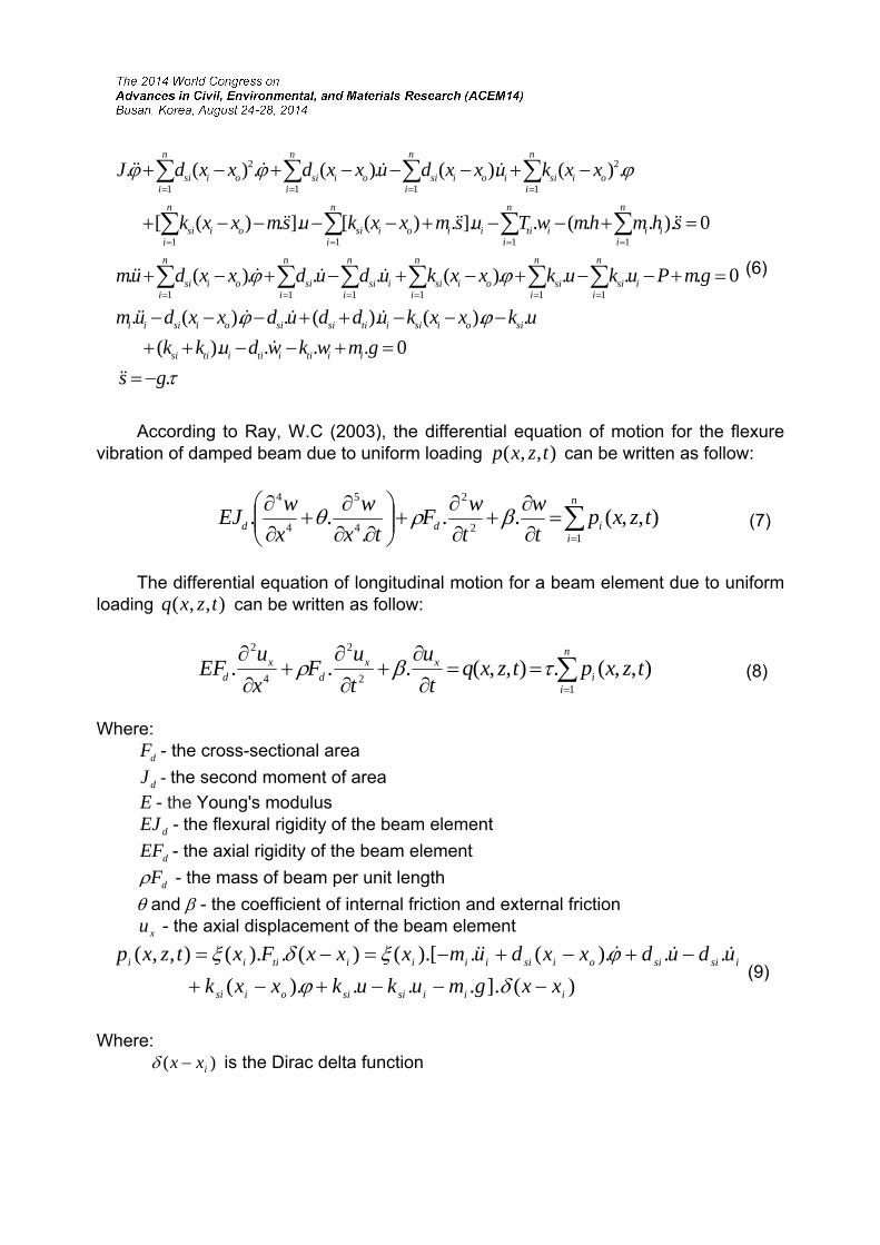
According to Ray, W.C (2003), the differential equation of motion for the flexure vibration of damped beam due to uniform loading ),,( tzxp can be written as follow:
n
iidd tzxp
t
w
t
wF
tx
w
x
wEJ
12
2
4
5
4
4
),,(...
.. (7)
The differential equation of longitudinal motion for a beam element due to uniform loading ),,( tzxq can be written as follow:
n
ii
xxd
xd tzxptzxq
t
u
t
uF
x
uEF
12
2
4
2
),,(.),,(... (8)
Where:
dF - the cross-sectional area
dJ - the second moment of area
E - the Young's modulus
dEJ - the flexural rigidity of the beam element
dEF - the axial rigidity of the beam element
dF - the mass of beam per unit length
and - the coefficient of internal friction and external friction
xu - the axial displacement of the beam element
)(.]...).(
..).(.[).()(.).(),,(
iiisisioisi
isisioisiiiiitiii
xxgmukukxxk
ududxxdumxxxFxtzxp
(9)
Where: )( ixx is the Dirac delta function
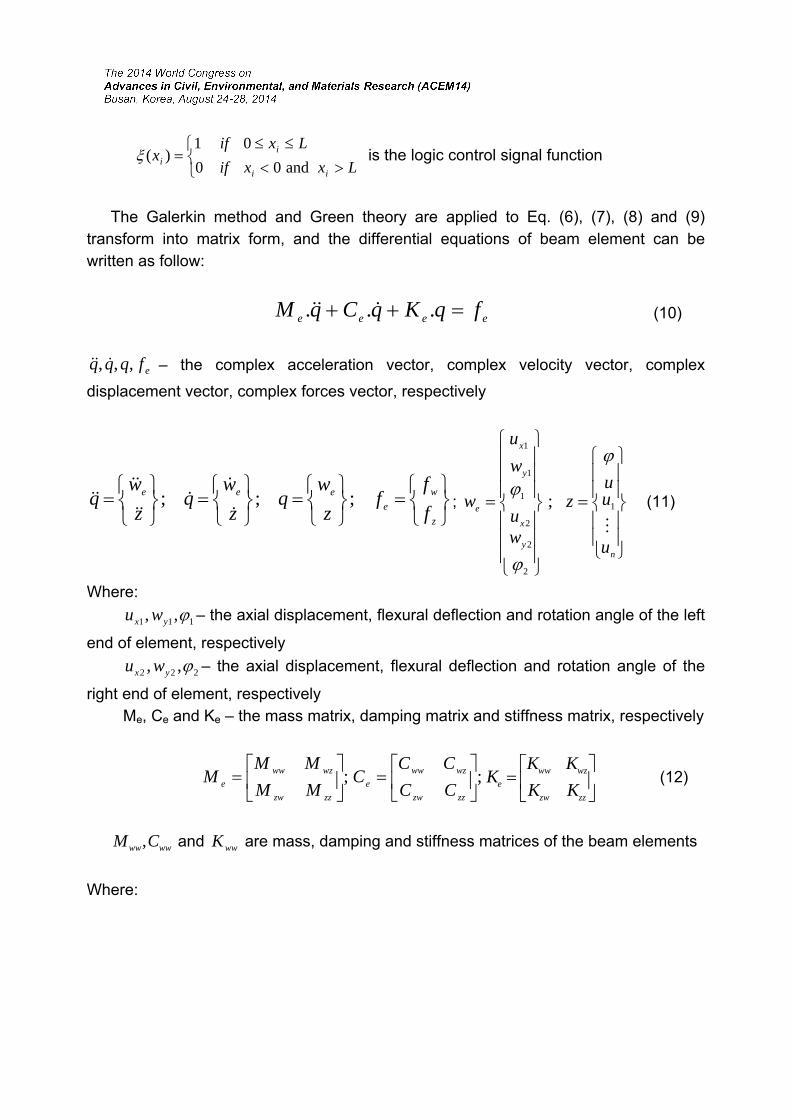
Lxxif
Lxifx
ii
ii and00
01)( is the logic control signal function
The Galerkin method and Green theory are applied to Eq. (6), (7), (8) and (9) transform into matrix form, and the differential equations of beam element can be written as follow:
eeee fqKqCqM ... (10)
efqqq ,,, – the complex acceleration vector, complex velocity vector, complex
displacement vector, complex forces vector, respectively
z
w
e
eee
f
ff
z
wq
z
wq
z
wq ;;;
;
ny
x
y
x
e
u
uu
z
wu
w
u
w
1
2
2
2
1
1
1
;
(11)
Where:
111 ,, yx wu – the axial displacement, flexural deflection and rotation angle of the left
end of element, respectively
222 ,, yx wu – the axial displacement, flexural deflection and rotation angle of the
right end of element, respectively Me, Ce and Ke – the mass matrix, damping matrix and stiffness matrix, respectively
;
zzzw
wzww
e MM
MMM ;
zzzw
wzww
e CC
CCC
zzzw
wzww
e KK
KKK (12)
wwww CM , and wwK are mass, damping and stiffness matrices of the beam elements
Where:
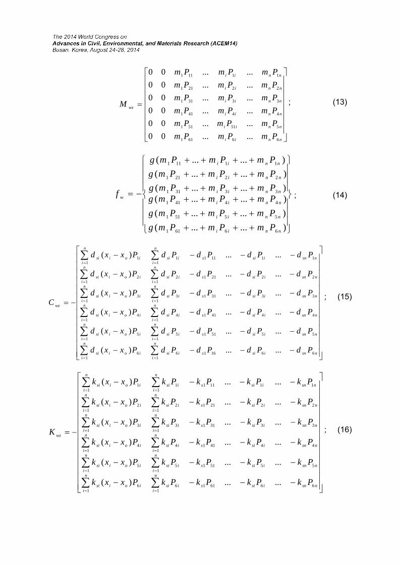
nnii
nnii
nnii
nnii
nnii
nnii
wz
PmPmPm
PmPmPm
PmPmPm
PmPmPm
PmPmPm
PmPmPm
M
66611
551511
44411
33311
22211
11111
......00
......00
......00
......00
......00
......00
; (13)
)......(
)......(
)......()......(
)......(
)......(
66611
55511
44411
33311
22211
11111
nnii
nnii
nnii
nnii
nnii
nnii
w
PmPmPmg
PmPmPmg
PmPmPmgPmPmPmg
PmPmPmg
PmPmPmg
f ; (14)
nsnisis
n
iisi
n
iioisi
nsnisis
n
iisi
n
iioisi
nsnisis
n
iisi
n
iioisi
nsnisis
n
iisi
n
iioisi
nsnisis
n
iisi
n
iioisi
nsnisis
n
iisi
n
iioisi
wz
PdPdPdPdPxxd
PdPdPdPdPxxd
PdPdPdPdPxxd
PdPdPdPdPxxd
PdPdPdPdPxxd
PdPdPdPdPxxd
C
661611
61
6
555111
51
5
444111
41
4
333111
31
3
222111
21
2
111111
11
1
......)(
......)(
......)(
......)(
......)(
......)(
; (15)
nsnisis
n
iisi
n
iioisi
nsnisis
n
iisi
n
iioisi
nsnisis
n
iisi
n
iioisi
nsnisis
n
iisi
n
iioisi
nsnisis
n
iisi
n
iioisi
nsnisis
n
iisi
n
iioisi
wz
PkPkPkPkPxxk
PkPkPkPkPxxk
PkPkPkPkPxxk
PkPkPkPkPxxk
PkPkPkPkPxxk
PkPkPkPkPxxk
K
666111
61
6
555111
51
5
444111
41
4
333111
31
3
222111
21
2
111111
11
1
......)(
......)(
......)(
......)(
......)(
......)(
; (16)
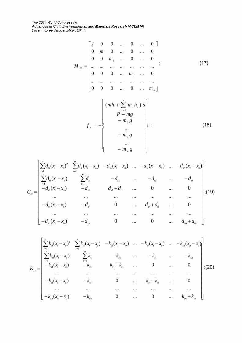
n
i
zz
m
m
m
m
J
M
...0...000
.....................
0......000
.....................
0...0...00
0...0...00
0...0...00
1; (17)
gm
gm
gmmgP
shmmh
f
n
i
n
iii
z
...
...
).(
1
1
; (18)
tnsnsnonsn
tisisioisi
tssos
snsis
n
isi
n
ioisi
onsnoisios
n
ioisi
n
ioisi
zz
dddxxd
dddxxd
dddxxd
ddddxxd
xxdxxdxxdxxdxxd
C
...0...0)(
.....................
0......0)(
.....................
0...0...)(
......)(
)(...)(...)()()(
11111
111
1111
2
;(19)
tnsnsnonsn
tisisioisi
tssos
snsis
n
isi
n
ioisi
onsnoisios
n
ioisi
n
ioisi
zz
kkkxxk
kkkxxk
kkkxxk
kkkkxxk
xxkxxkxxkxxkxxk
K
...0...0)(
.....................
0......0)(
.....................
0...0...)(
......)(
)(...)(...)()()(
11111
111
1111
2
;(20)
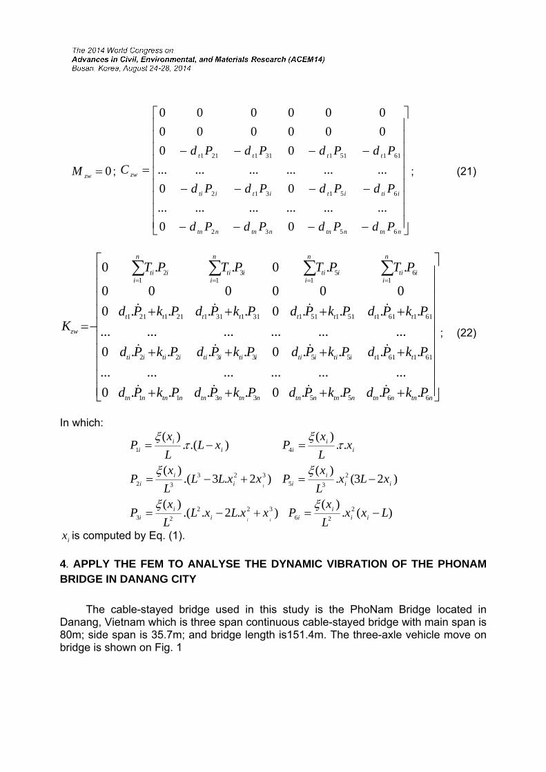
0zwM ;
ntnntnntnntn
itiitititi
tttt
zw
PdPdPdPd
PdPdPdPd
PdPdPdPd
C
6532
651312
611511311211
00
..................
00
..................
00
000000
000000
; (21)
ntnntnntnntnntnntnntnntn
ttitiitiitiitiitiiti
tttttttt
n
iiti
n
iiti
n
iiti
n
iiti
zw
PkPdPkPdPkPdPkPd
PkPdPkPdPkPdPkPd
PkPdPkPdPkPdPkPd
PTPTPTPT
K
66553311
611611553322
611611511511311311211211
16
15
13
12
....0....0
..................
....0....0
..................
....0....0
000000
..0..0
; (22)
In which:
)(.)(
).2..()(
)23(.)(
..)(
)2.3.()(
).(.)(
2
26322
23
2
35
4
323
32
1
LxxL
xPxxLxL
L
xP
xLxL
xP
xL
xP
xxLLL
xP
xLL
xP
iii
iii
i
iii
i
ii
i
ii
i
ii
i
ii
i
ix is computed by Eq. (1).
4. APPLY THE FEM TO ANALYSE THE DYNAMIC VIBRATION OF THE PHONAM BRIDGE IN DANANG CITY
The cable-stayed bridge used in this study is the PhoNam Bridge located in Danang, Vietnam which is three span continuous cable-stayed bridge with main span is 80m; side span is 35.7m; and bridge length is151.4m. The three-axle vehicle move on bridge is shown on Fig. 1

Apply the FEM and the algorithm of the FEM can be found in Zienkiewicz (2000), we have the dynamic vibration differential equation for the system as in Eq. (23).
FQKQCQM eee ... (23)
In which:
CKM ,, – the mass matrix, damping matrix and stiffness matrix of system.
FQQQ ,,, – the acceleration vector, the velocity vector, the deflection vector and the force vector of the system.
After imposing boundary and initial conditions on Eq. (23), we can solve this
equation by the Runge-Kutta-Merson method. The numerical values of the vehicle and bridge parameters were used in the computer simulation and the field test as follows:
The parameters of the PhoNam Cable-stayed bridge:
1 2 3 4 5
10 9 8 7 6
20 19 18 17
16
11 12
13 14 15
T1
T2
T1
T2
Fig. 3 The cables plane of PhoNam bridge
- The Cable properties:
Cross sectional area of Cable No. 4, 5, 6, 7, 14, 15, 16, 17 : A=980 mm2 Cross sectional area of Cable No. 2, 3, 8, 9, 12, 13, 18,19 : A=1260 mm2 Cross sectional area of Cable No. 1, 10, 11, 20 : A=1680 mm2
- The Rigid Beam properties:
E= 2.1x10⁸ T/m2, Jd= 0.001702m4, Fd = 0.02568m2, qy=Fd = 2.035T/m, =0.027; =0.01, g = 9,81m/s2, = 0.25.
- The Tower properties:
The part T1: E= 2.1x10⁸ T/m2, Jd=0.00598036m4, Fd = 0.04706m2, qx=0.406T/m, =0.027; =0.01.
The part T2: E= 2.1x10⁸ T/m2, Jd=0.00439952 m4, Fd = 0.0346m2, qx=0.406T/m, =0.027; =0.01.
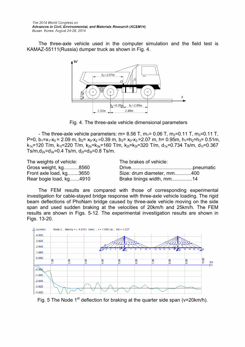
The three-axle vehicle used in the computer simulation and the field test is KAMAZ-55111(Russia) dumper truck as shown in Fig. 4.
1.32m 2.48m
x
b1=2.09m
O
b3=2.07m
b2=0.39m
0.51
m
w
Fig. 4. The three-axle vehicle dimensional parameters
- The three-axle vehicle parameters: m= 8.56 T, m1= 0.06 T, m2=0.11 T, m3=0.11 T, P=0, b1=x1-x0 = 2.09 m, b2= x0-x2 =0.39 m, b3= x0-x3 =2.07 m, h= 0.95m, h1=h2=h3= 0.51m, k1s=120 T/m, k1t=220 T/m, k2s=k3s=160 T/m, k2t=k3t=320 T/m, d1s=0.734 Ts/m, d1t=0.367 Ts/m,d2s=d3s=0.4 Ts/m, d2t=d3t=0.8 Ts/m.
The weights of vehicle: Gross weight, kg...........8560 Front axle load, kg........3650 Rear bogie load, kg.......4910
The brakes of vehicle: Drive.............................................pneumaticSize: drum diameter, mm............400 Brake linings width, mm...............14
The FEM results are compared with those of corresponding experimental
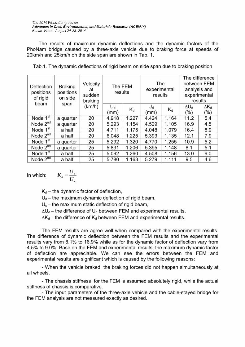
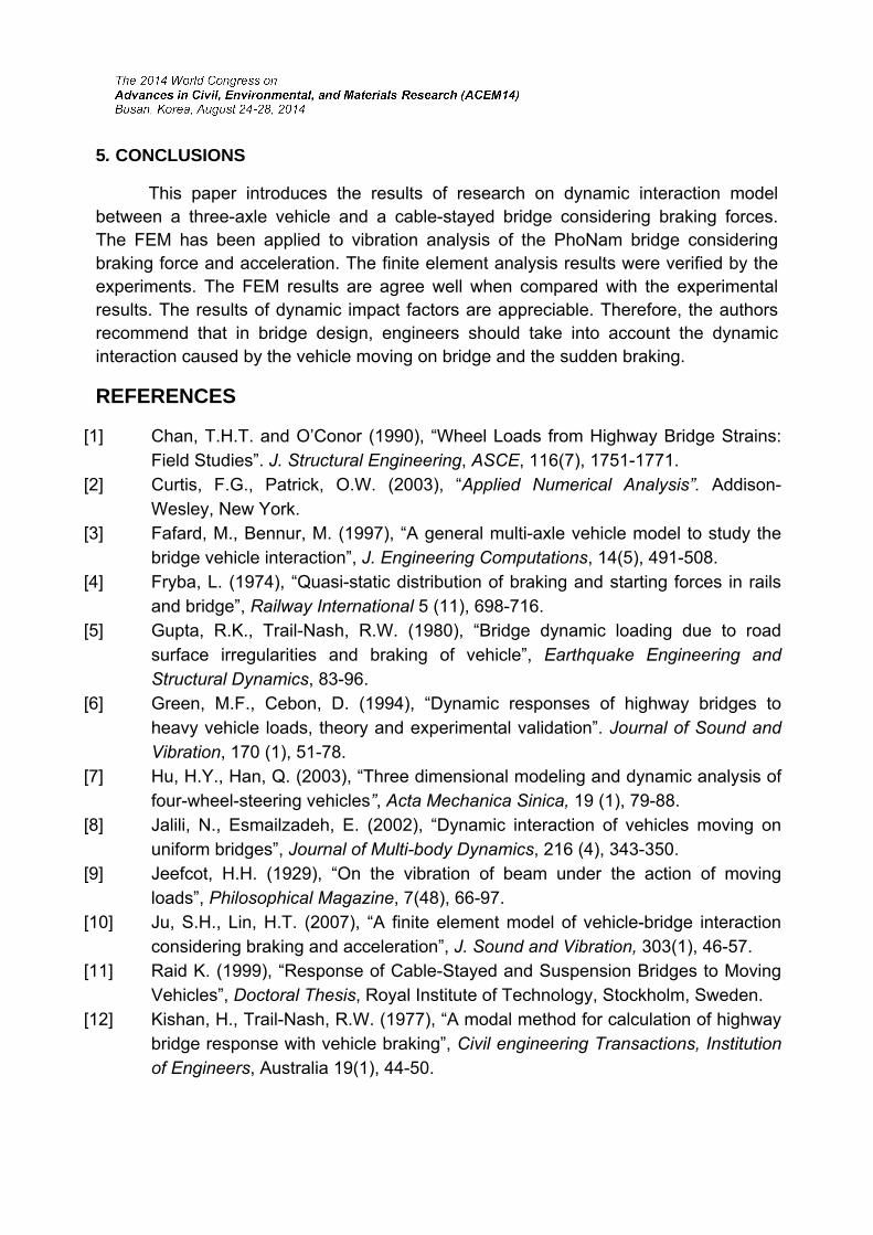
investigation for cable-stayed bridge response with three-axle vehicle loading. The rigid beam deflections of PhoNam bridge caused by three-axle vehicle moving on the side span and used sudden braking at the velocities of 20km/h and 25km/h. The FEM results are shown in Figs. 5-12. The experimental investigation results are shown in Figs. 13-20.
Fig. 5 The Node 1st deflection for braking at the quarter side span (v=20km/h).
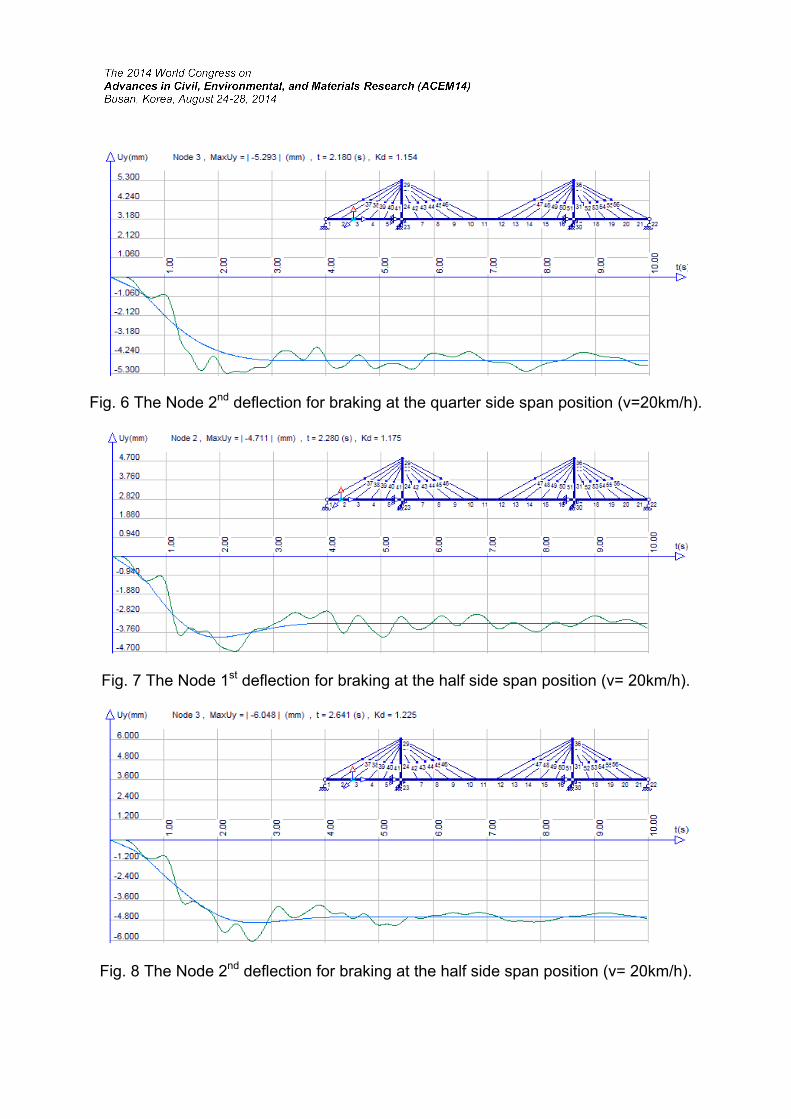
Fig. 6 The Node 2nd deflection for braking at the quarter side span position (v=20km/h).
Fig. 7 The Node 1st deflection for braking at the half side span position (v= 20km/h).
Fig. 8 The Node 2nd deflection for braking at the half side span position (v= 20km/h).
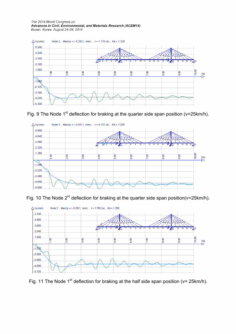
Fig. 9 The Node 1st deflection for braking at the quarter side span position (v=25km/h).
Fig. 10 The Node 2nt deflection for braking at the quarter side span position(v=25km/h).
Fig. 11 The Node 1st deflection for braking at the half side span position (v= 25km/h).
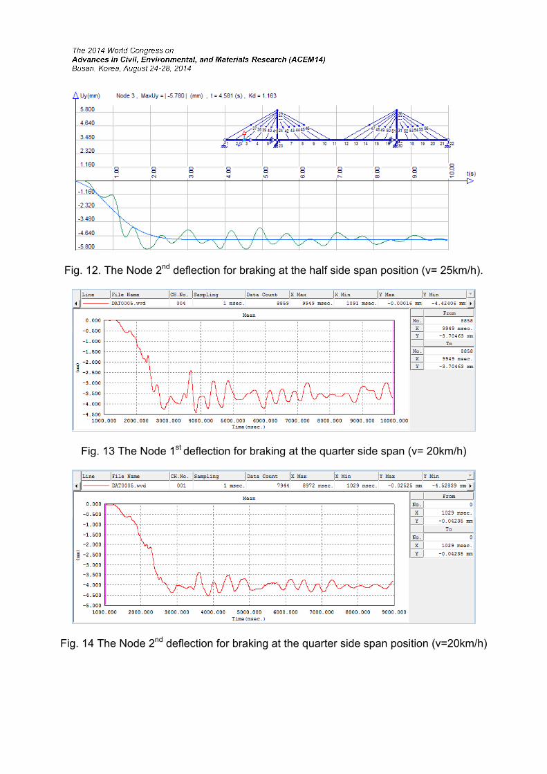
Fig. 12. The Node 2nd deflection for braking at the half side span position (v= 25km/h).
Fig. 13 The Node 1st deflection for braking at the quarter side span (v= 20km/h)
Fig. 14 The Node 2nd deflection for braking at the quarter side span position (v=20km/h)
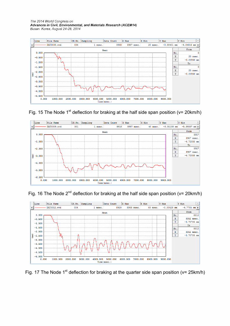
Fig. 15 The Node 1st deflection for braking at the half side span position (v= 20km/h)
Fig. 16 The Node 2nd deflection for braking at the half side span position (v= 20km/h)
Fig. 17 The Node 1st deflection for braking at the quarter side span position (v= 25km/h)
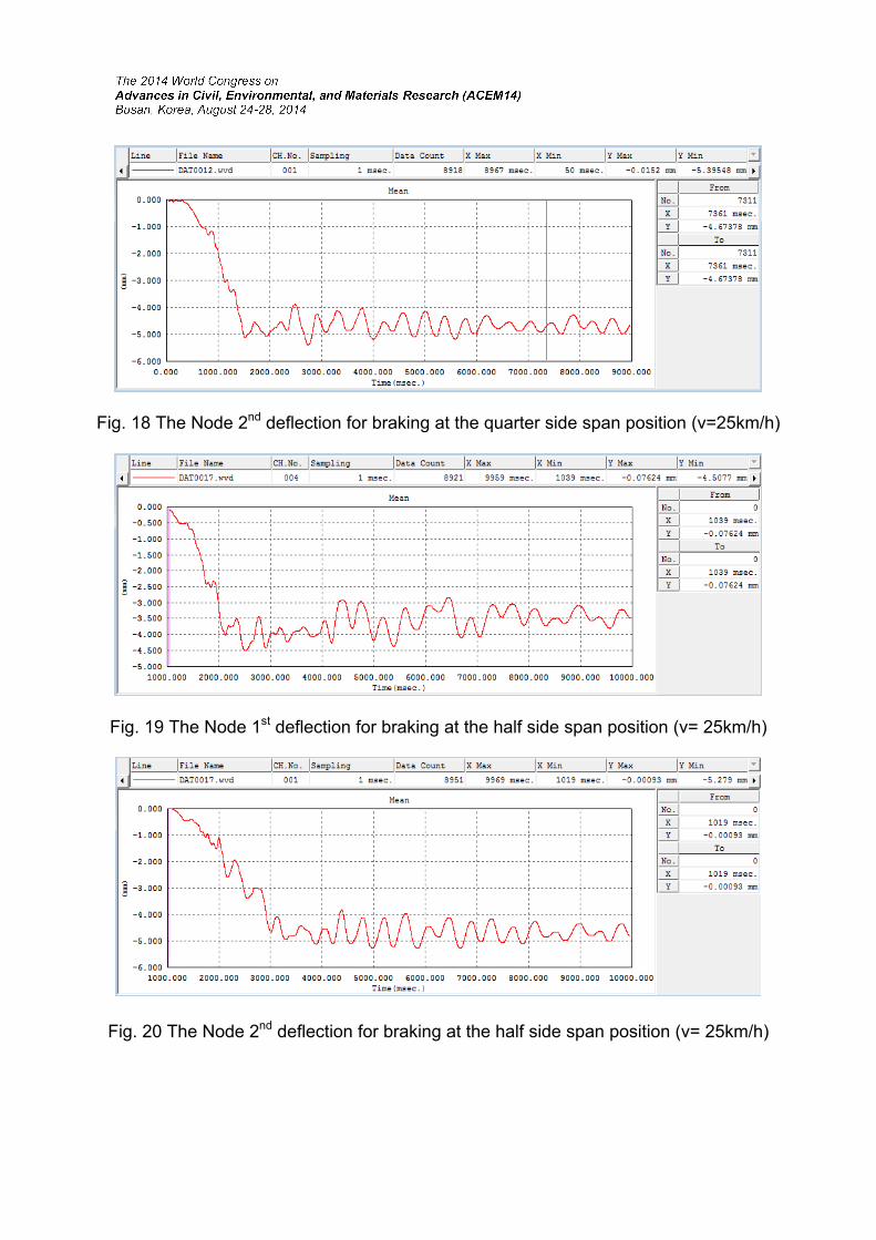
Fig. 18 The Node 2nd deflection for braking at the quarter side span position (v=25km/h)
Fig. 19 The Node 1st deflection for braking at the half side span position (v= 25km/h)
Fig. 20 The Node 2nd deflection for braking at the half side span position (v= 25km/h)
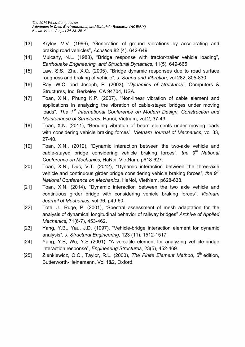
The results of maximum dynamic deflections and the dynamic factors of the PhoNam bridge caused by a three-axle vehicle due to braking force at speeds of 20km/h and 25km/h on the side span are shown in Tab. 1.
Tab.1. The dynamic deflections of rigid beam on side span due to braking position
Deflection positions of rigid beam
Braking positions on side span
Velocity at
sudden braking (km/h)
The FEM results
The experimental
results
The difference between FEM analysis and experimental
results Ud
(mm) Kd
Ud
(mm) Kd
∆Ud (%)
∆Kd (%)
Node 1st a quarter 20 4.918 1.227 4.424 1.164 11.2 5.4 Node 2nd a quarter 20 5.293 1.154 4.529 1.105 16.9 4.5 Node 1st a half 20 4.711 1.175 4.048 1.079 16.4 8.9 Node 2nd a half 20 6.048 1.225 5.393 1.135 12.1 7.9 Node 1st a quarter 25 5.292 1.320 4.770 1.255 10.9 5.2 Node 2nd a quarter 25 5.831 1.206 5.395 1.148 8.1 5.1 Node 1st a half 25 5.092 1.260 4.508 1.156 13.0 9.0 Node 2nd a half 25 5.780 1.163 5.279 1.111 9.5 4.6
In which: s
dd U
UK
Kd – the dynamic factor of deflection, Ud – the maximum dynamic deflection of rigid beam, Us – the maximum static deflection of rigid beam,
∆Ud – the difference of Ud between FEM and experimental results, ∆Kd – the difference of Kd between FEM and experimental results. The FEM results are agree well when compared with the experimental results.
The difference of dynamic deflection between the FEM results and the experimental results vary from 8.1% to 16.9% while as for the dynamic factor of deflection vary from 4.5% to 9.0%. Base on the FEM and experimental results, the maximum dynamic factor of deflection are appreciable. We can see the errors between the FEM and experimental results are significant which is caused by the following reasons:
- When the vehicle braked, the braking forces did not happen simultaneously at all wheels.
- The chassis stiffness for the FEM is assumed absolutely rigid, while the actual stiffness of chassis is comparative.
- The input parameters of the three-axle vehicle and the cable-stayed bridge for the FEM analysis are not measured exactly as desired.
5. CONCLUSIONS
This paper introduces the results of research on dynamic interaction model between a three-axle vehicle and a cable-stayed bridge considering braking forces. The FEM has been applied to vibration analysis of the PhoNam bridge considering braking force and acceleration. The finite element analysis results were verified by the experiments. The FEM results are agree well when compared with the experimental results. The results of dynamic impact factors are appreciable. Therefore, the authors recommend that in bridge design, engineers should take into account the dynamic interaction caused by the vehicle moving on bridge and the sudden braking.
REFERENCES
[1] Chan, T.H.T. and O’Conor (1990), “Wheel Loads from Highway Bridge Strains: Field Studies”. J. Structural Engineering, ASCE, 116(7), 1751-1771.
[2] Curtis, F.G., Patrick, O.W. (2003), “Applied Numerical Analysis”. Addison-Wesley, New York.
[3] Fafard, M., Bennur, M. (1997), “A general multi-axle vehicle model to study the bridge vehicle interaction”, J. Engineering Computations, 14(5), 491-508.
[4] Fryba, L. (1974), “Quasi-static distribution of braking and starting forces in rails and bridge”, Railway International 5 (11), 698-716.
[5] Gupta, R.K., Trail-Nash, R.W. (1980), “Bridge dynamic loading due to road surface irregularities and braking of vehicle”, Earthquake Engineering and Structural Dynamics, 83-96.
[6] Green, M.F., Cebon, D. (1994), “Dynamic responses of highway bridges to heavy vehicle loads, theory and experimental validation”. Journal of Sound and Vibration, 170 (1), 51-78.
[7] Hu, H.Y., Han, Q. (2003), “Three dimensional modeling and dynamic analysis of four-wheel-steering vehicles”, Acta Mechanica Sinica, 19 (1), 79-88.
[8] Jalili, N., Esmailzadeh, E. (2002), “Dynamic interaction of vehicles moving on uniform bridges”, Journal of Multi-body Dynamics, 216 (4), 343-350.
[9] Jeefcot, H.H. (1929), “On the vibration of beam under the action of moving loads”, Philosophical Magazine, 7(48), 66-97.
[10] Ju, S.H., Lin, H.T. (2007), “A finite element model of vehicle-bridge interaction considering braking and acceleration”, J. Sound and Vibration, 303(1), 46-57.
[11] Raid K. (1999), “Response of Cable-Stayed and Suspension Bridges to Moving Vehicles”, Doctoral Thesis, Royal Institute of Technology, Stockholm, Sweden.
[12] Kishan, H., Trail-Nash, R.W. (1977), “A modal method for calculation of highway bridge response with vehicle braking”, Civil engineering Transactions, Institution of Engineers, Australia 19(1), 44-50.
[13] Krylov, V.V. (1996), “Generation of ground vibrations by accelerating and braking road vehicles”, Acustica 82 (4), 642-649.
[14] Mulcahy, N.L. (1983), “Bridge response with tractor-trailer vehicle loading”, Earthquake Engineering and Structural Dynamics, 11(5), 649-665.
[15] Law, S.S., Zhu, X.Q. (2005), “Bridge dynamic responses due to road surface roughess and braking of vehicle”, J. Sound and Vibration, vol 282, 805-830.
[16] Ray, W.C. and Joseph, P. (2003), “Dynamics of structures”, Computers & Structures, Inc. Berkeley, CA 94704, USA.
[17] Toan, X.N., Phung K.P. (2007), “Non-linear vibration of cable element and applications in analyzing the vibration of cable-stayed bridges under moving loads". The 1st International Conference on Modern Design, Construction and Maintenance of Structures, Hanoi, Vietnam, vol 2, 37-43.
[18] Toan, X.N. (2011), “Bending vibration of beam elements under moving loads with considering vehicle braking forces”, Vietnam Journal of Mechanics, vol 33, 27-40.
[19] Toan, X.N., (2012), “Dynamic interaction between the two-axle vehicle and cable-stayed bridge considering vehicle braking forces”, the 9th National Conference on Mechanics, HaNoi, VietNam, p618-627.
[20] Toan, X.N., Duc, V.T. (2012), “Dynamic interaction between the three-axle vehicle and continuous girder bridge considering vehicle braking forces”, the 9th
National Conference on Mechanics, HaNoi, VietNam, p628-638. [21] Toan, X.N. (2014), “Dynamic interaction between the two axle vehicle and
continuous girder bridge with considering vehicle braking forces”, Vietnam Journal of Mechanics, vol 36, p49-60.
[22] Toth, J., Ruge, P. (2001), “Spectral assessment of mesh adaptation for the analysis of dynamical longitudinal behavior of railway bridges” Archive of Applied Mechanics, 71(6-7), 453-462.
[23] Yang, Y.B., Yau, J.D. (1997), “Vehicle-bridge interaction element for dynamic analysis”, J. Structural Engineering, 123 (11), 1512-1517.
[24] Yang, Y.B, Wu, Y.S (2001), “A versatile element for analyzing vehicle-bridge interaction response”, Engineering Structures, 23(5), 452-469.
[25] Zienkiewicz, O.C., Taylor, R.L. (2000), The Finite Element Method, 5th edition, Butterworth-Heinemann, Vol 1&2, Oxford.