Embed Size (px)
Citation preview
A Flexible Virtual Development Environment for Embedded Systems
2007. 6. 21.
Sang-Young Cho, Yoojin Chung, and Jung-Bae Lee*
CSE, Hankuk University of Foreign Studies*CI, Sunmoon University
1
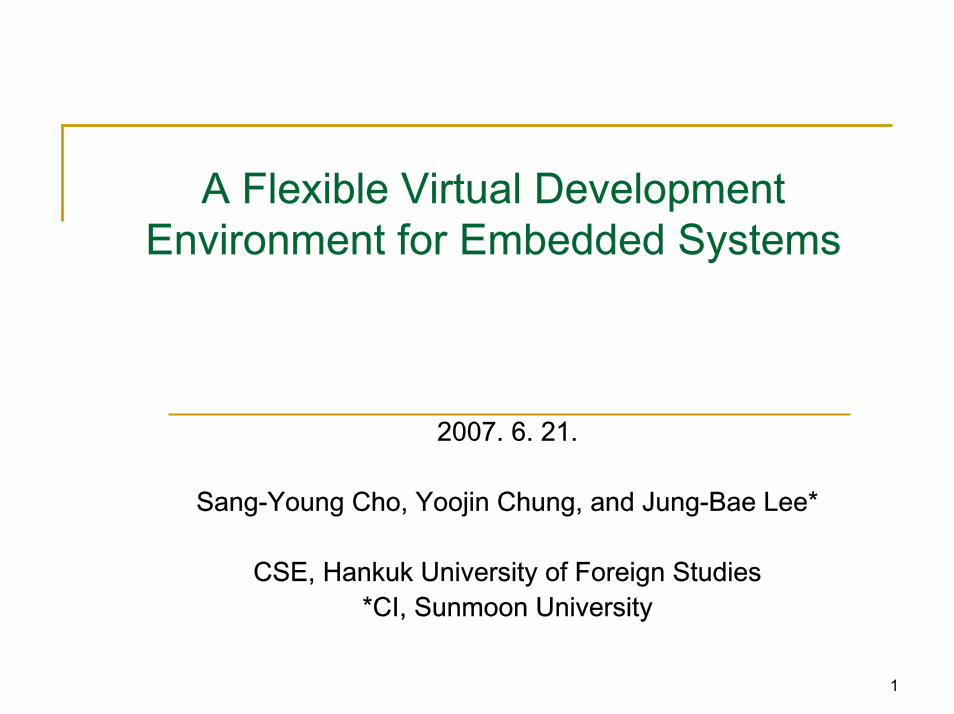
ContentsIntroduction
Why and What is Virtual Development EnvironmentExamples and Our Approach
Related ResearchARMulator and SystemC Environment
Design and ImplementationExtension of ARMulator EnvironmentExtension with SystemC ModelsImplemented VDE and uC/OS-II PortingVerifying VDE
Conclusions
2
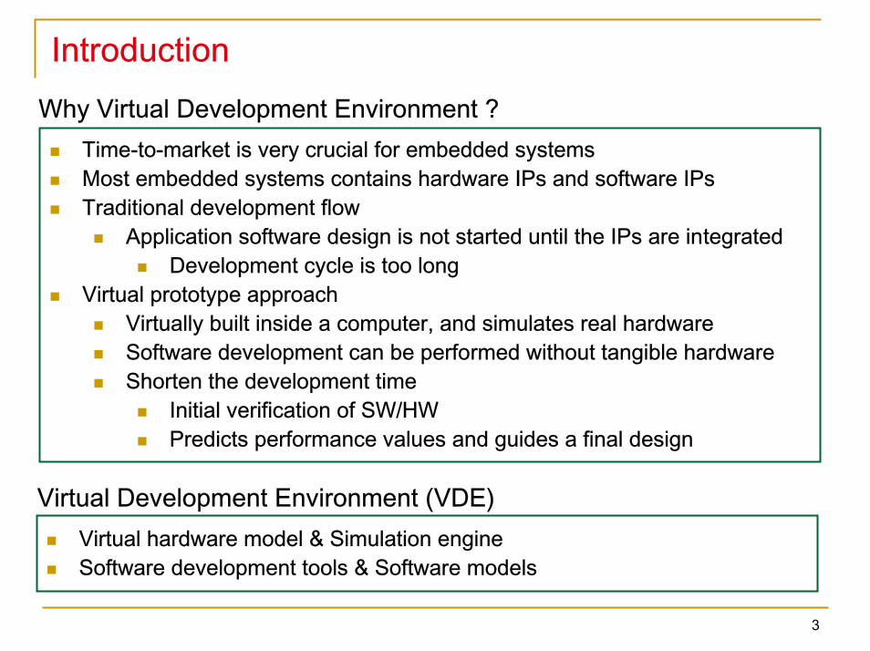
IntroductionWhy Virtual Development Environment ?
Time-to-market is very crucial for embedded systemsMost embedded systems contains hardware IPs and software IPsTraditional development flow
Application software design is not started until the IPs are integratedDevelopment cycle is too long
Virtual prototype approachVirtually built inside a computer, and simulates real hardwareSoftware development can be performed without tangible hardwareShorten the development time
Initial verification of SW/HWPredicts performance values and guides a final design
Virtual hardware model & Simulation engineSoftware development tools & Software models
Virtual Development Environment (VDE)
3
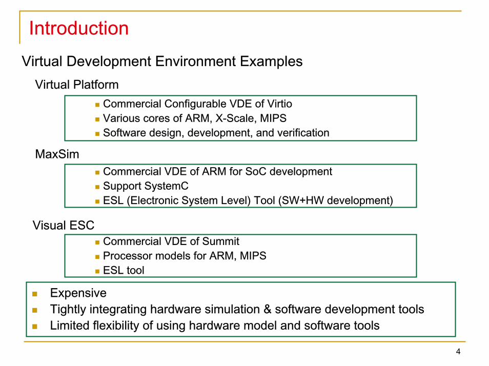
IntroductionVirtual Development Environment Examples
Virtual PlatformCommercial Configurable VDE of VirtioVarious cores of ARM, X-Scale, MIPSSoftware design, development, and verification
MaxSimCommercial VDE of ARM for SoC developmentSupport SystemCESL (Electronic System Level) Tool (SW+HW development)
Visual ESCCommercial VDE of Summit Processor models for ARM, MIPSESL tool
Expensive Tightly integrating hardware simulation & software development tools Limited flexibility of using hardware model and software tools
4
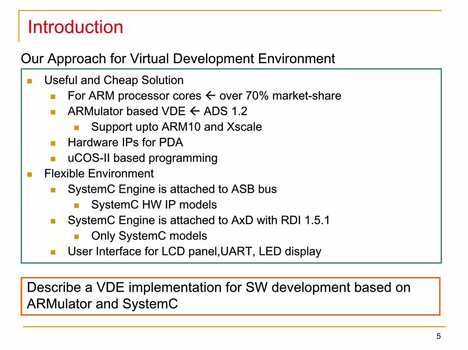
IntroductionOur Approach for Virtual Development Environment
Useful and Cheap SolutionFor ARM processor cores over 70% market-shareARMulator based VDE ADS 1.2
Support upto ARM10 and XscaleHardware IPs for PDAuCOS-II based programming
Flexible EnvironmentSystemC Engine is attached to ASB bus
SystemC HW IP modelsSystemC Engine is attached to AxD with RDI 1.5.1
Only SystemC modelsUser Interface for LCD panel,UART, LED display
Describe a VDE implementation for SW development based onARMulator and SystemC
5
Related Studies: ARMulator Environment
debugger
Peripherals
OS model(semi-hosting)
Debugging & Benchmarking &
Utility model
ARMulator
RDI protocol
Coprocessor
Configuration file(*.ami, *.dsc)
ReadMemorySystem
Extension interface
Core
ConfigRDI infoHandler
Moduleagent
Hostinterface
SimulationKernel
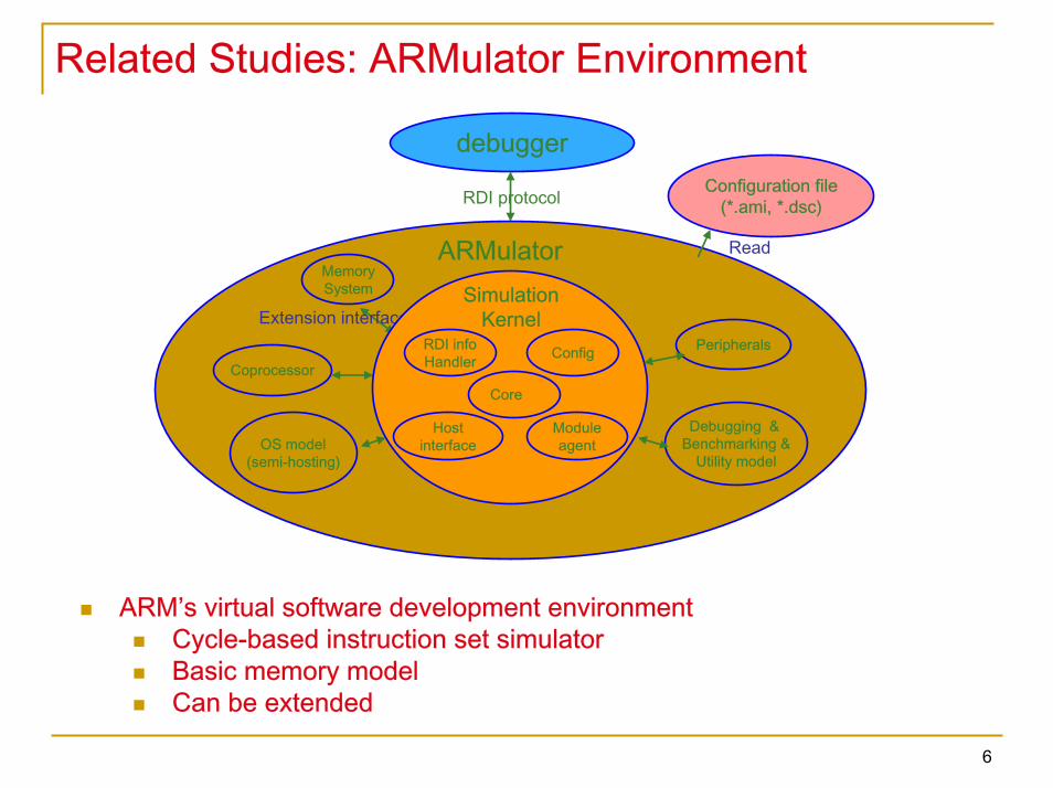
ARM’s virtual software development environmentCycle-based instruction set simulatorBasic memory modelCan be extended
6
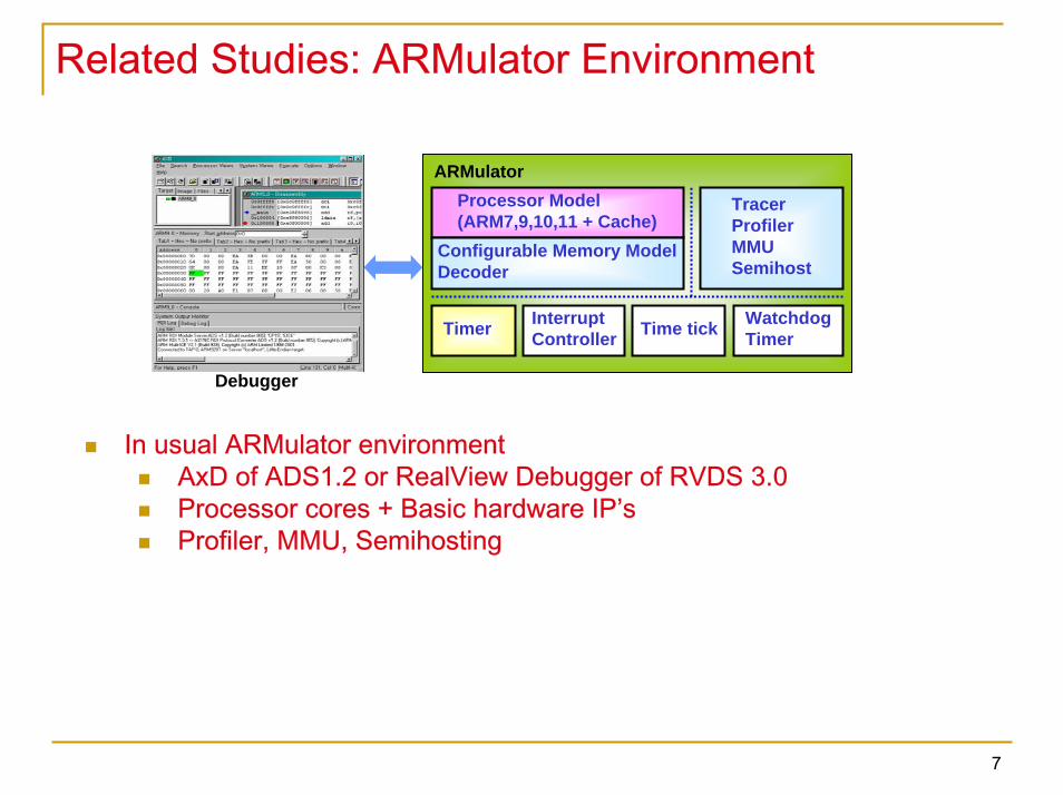
Related Studies: ARMulator Environment
ARMulatorProcessor Model(ARM7,9,10,11 + Cache)
Configurable Memory ModelDecoder
Timer InterruptController
TracerProfilerMMUSemihost
Time tick WatchdogTimer
Debugger
In usual ARMulator environmentAxD of ADS1.2 or RealView Debugger of RVDS 3.0Processor cores + Basic hardware IP’sProfiler, MMU, Semihosting
7
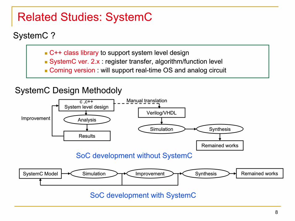
Related Studies: SystemCSystemC ?
C++ class library to support system level designSystemC ver. 2.x : register transfer, algorithm/function levelComing version : will support real-time OS and analog circuit
SystemC Design Methodolyc ,c++
System level designVerilog/VHDL
Simulation
Manual translation
Synthesis
AnalysisImprovement
Results
Remained works
SoC development without SystemC
Simulation Synthesis Remained worksSystemC Model Improvement
SoC development with SystemC
8
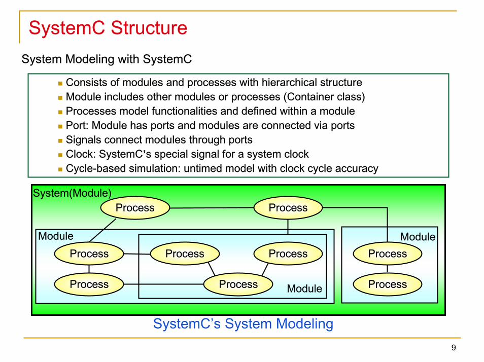
SystemC StructureSystem Modeling with SystemC
Consists of modules and processes with hierarchical structureModule includes other modules or processes (Container class)Processes model functionalities and defined within a modulePort: Module has ports and modules are connected via portsSignals connect modules through portsClock: SystemC’s special signal for a system clockCycle-based simulation: untimed model with clock cycle accuracy
Module
System(Module)
Module
SystemC’s System Modeling
Process
Process Process
Process
ProcessProcess ProcessProcess
Process Module
9
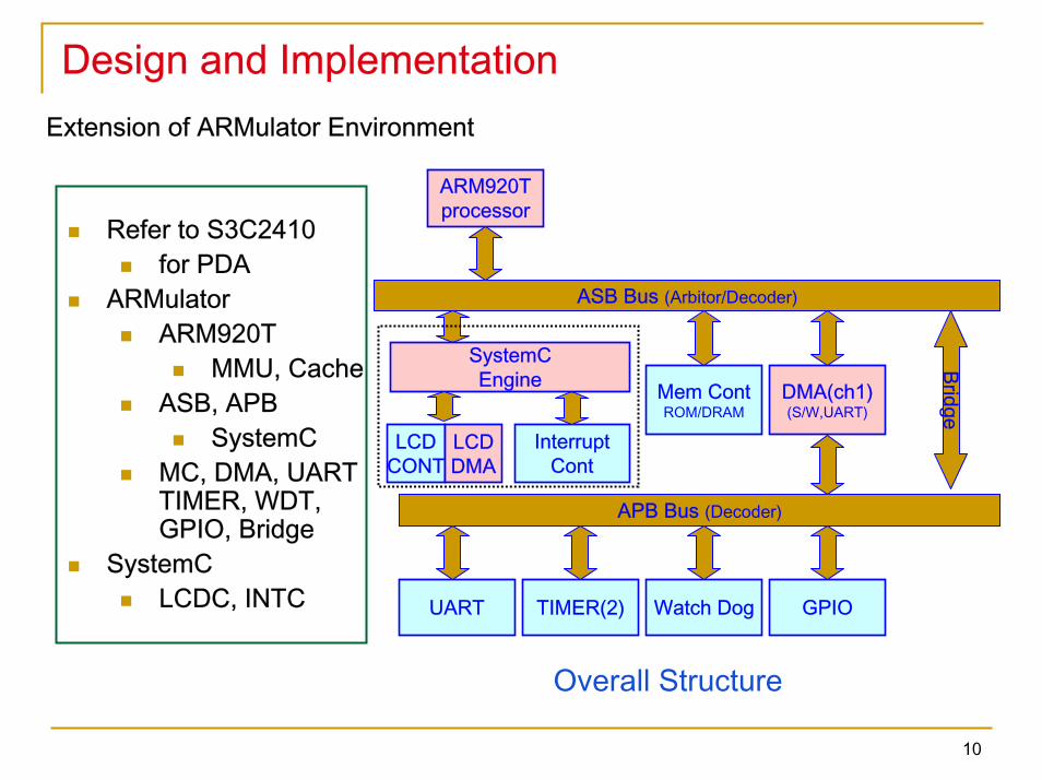
Design and ImplementationExtension of ARMulator Environment
Overall Structure
ARM920Tprocessor
ASB Bus (Arbitor/Decoder)
LCDCONT
InterruptCont
Mem ContROM/DRAM
DMA(ch1)(S/W,UART)
APB Bus (Decoder)
UART TIMER(2) Watch Dog GPIO
LCDDMA
Bridge
SystemCEngine
Refer to S3C2410for PDA
ARMulatorARM920T
MMU, CacheASB, APB
SystemC MC, DMA, UARTTIMER, WDT,GPIO, Bridge
SystemCLCDC, INTC
10
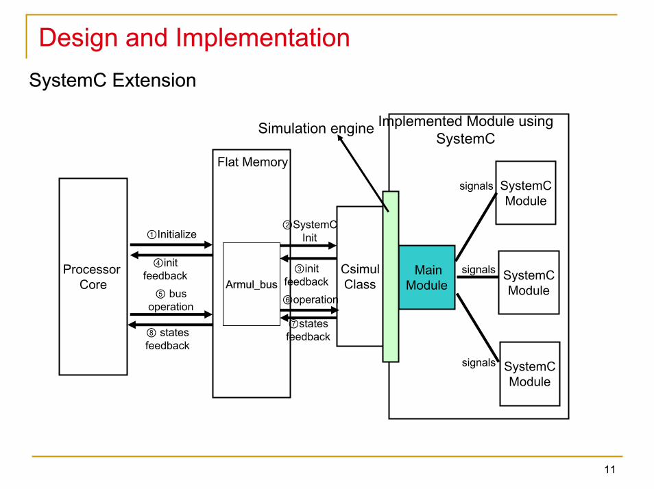
Design and ImplementationSystemC Extension
Processor Core
CsimulClassArmul_bus
SystemCModule
SystemCModule
SystemCModule
MainModule
Flat Memory
Implemented Module using SystemC
②SystemCInit
③init feedback
④initfeedback
⑤ bus operation ⑥operation
⑦states feedback
signals
signals
signals
⑧ statesfeedback
①Initialize
Simulation engine
11
Design and ImplementationSystemC Extension
In InitializeModule() function of Armul_busSystemC modules are initialized by Csimul class SystemC.lib is modified
Main() sc_main()Clock is synchronized with ASB clock
Csimul behaviorGenerates modulesMake sc_signal to control input/output wires of modulesConnect signals after a main module in SystemC is madeCreate functions for read/write of connected modulesDuring simulation, a callback function is called by Armul_busAllow simulation result to be reported to Armul_bus
SystemC engine is connected to ASB bus
12
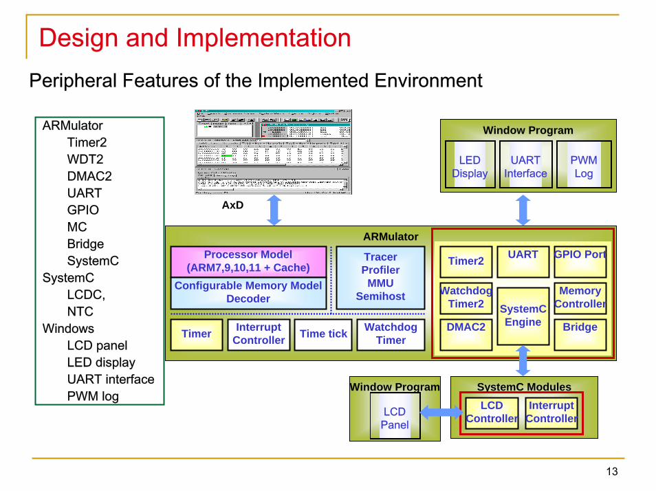
Design and ImplementationPeripheral Features of the Implemented Environment
Window Program SystemC Modules
ARMulatorUART
LCDController
Processor Model(ARM7,9,10,11 + Cache)
Configurable Memory ModelDecoder
Timer InterruptController
TracerProfilerMMU
Semihost
Time tick WatchdogTimer
Timer2
WatchdogTimer2
DMAC2
InterruptController
GPIO Port
Bridge
MemoryController
Window Program
LCDPanel
UARTInterface
LEDDisplay
PWMLog
AxD
SystemCEngine
ARMulatorTimer2WDT2DMAC2UARTGPIOMCBridgeSystemC
SystemCLCDC,NTC
WindowsLCD panelLED displayUART interfacePWM log
13
Design and Implementation
14
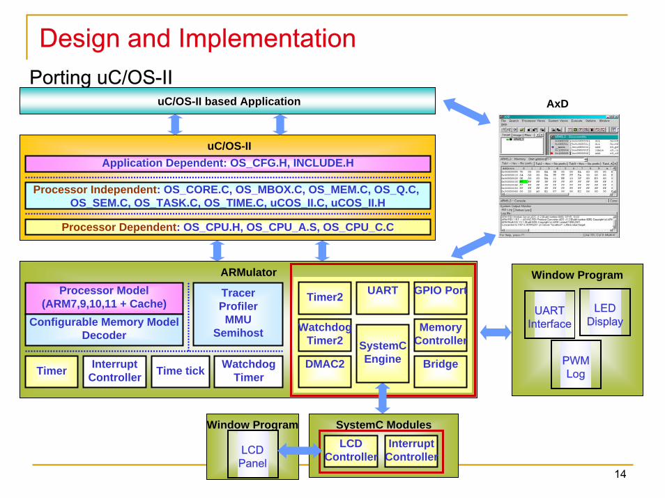
Porting uC/OS-II
uC/OS-II
Processor Independent: OS_CORE.C, OS_MBOX.C, OS_MEM.C, OS_Q.C, OS_SEM.C, OS_TASK.C, OS_TIME.C, uCOS_II.C, uCOS_II.H
Processor Dependent: OS_CPU.H, OS_CPU_A.S, OS_CPU_C.C
Application Dependent: OS_CFG.H, INCLUDE.H
uC/OS-II based Application
ARMulatorUARTProcessor Model
(ARM7,9,10,11 + Cache)Configurable Memory Model
Decoder
Timer InterruptController
TracerProfilerMMU
Semihost
Time tick WatchdogTimer
Timer2
WatchdogTimer2
DMAC2
GPIO Port
Bridge
MemoryController
Window Program
UARTInterface
LEDDisplay
PWMLog
AxD
Window Program SystemC ModulesLCD
ControllerInterrupt
ControllerLCDPanel
SystemCEngine
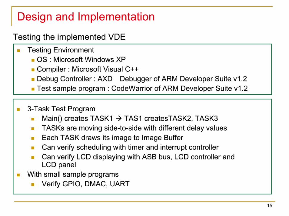
Design and ImplementationTesting the implemented VDE
Testing EnvironmentOS : Microsoft Windows XP Compiler : Microsoft Visual C++ Debug Controller : AXD Debugger of ARM Developer Suite v1.2Test sample program : CodeWarrior of ARM Developer Suite v1.2
3-Task Test ProgramMain() creates TASK1 TAS1 createsTASK2, TASK3TASKs are moving side-to-side with different delay valuesEach TASK draws its image to Image BufferCan verify scheduling with timer and interrupt controllerCan verify LCD displaying with ASB bus, LCD controller and LCD panel
With small sample programsVerify GPIO, DMAC, UART
15
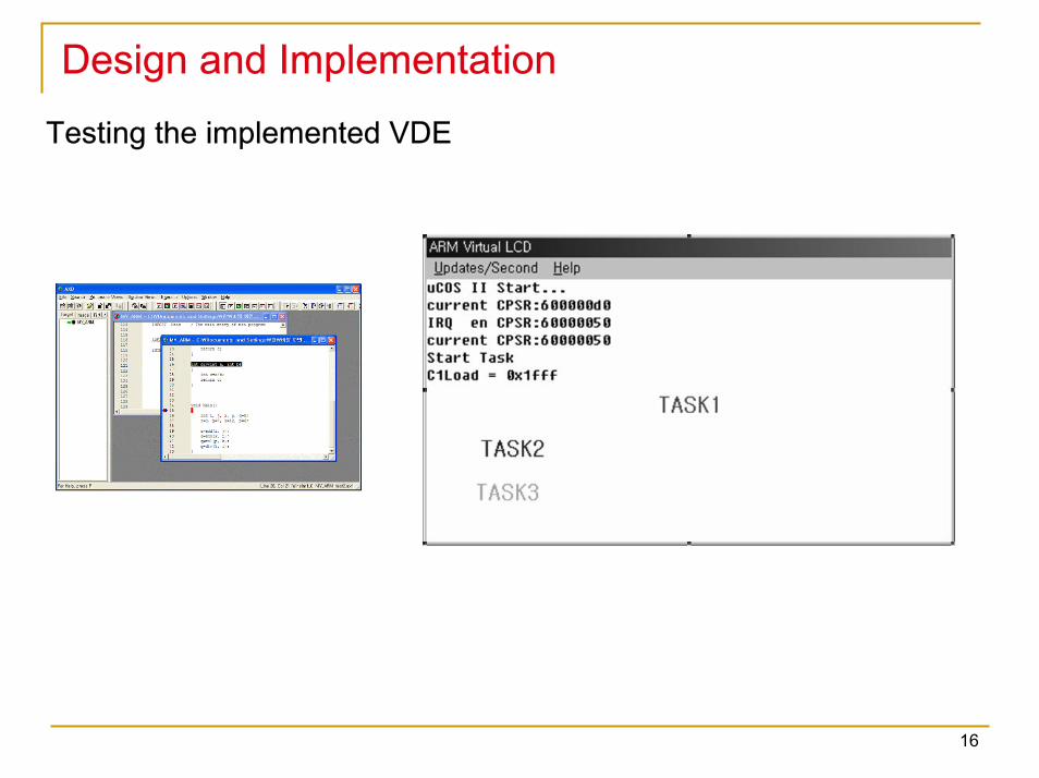
Design and ImplementationTesting the implemented VDE
16
ConclusionVirtual Development Environment (VDE)
Provide embedded software development environment without real hardware Reduce embedded system development cost
We implemented a flexible VDE with ARMulator and SystemC modelsTarget processor core adapts ARM920T processor core widely used in commercial Debugger ARM’s AxDExtension of ARMulator: TIMER, WDT, MC, DMAC, UART, GPIO, SystemC engineSystemC Module LCD Controller, Interrupt ControllerUser Interface LCD panel, LED display, UART int., PWM logginguC/OS-II Porting Multi-threaded application
Benefits of the implemented VDEMulti-modeling
ARMulator model and SystemC modelMulti-threaded programming
With uC/OS-II APIConstruct cost is very low
ADS 1.2 with public SystemC models
17