Embed Size (px)
Citation preview
A Framework for Building CustomisedCORBA ORBs
A thesis submitted to theUniversity of Dublin, Trinity College,
In fulfilment of the requirements for the degree ofMaster of Science (Computer Science)
Hubertus Wiese, BE, H.Dip.App.Sc.,Department of Computer Science,
Trinity College, Dublin
September 1998
2
Declaration
I, the undersigned, declare that this work has not previously been submitted as an
exercise for a degree at this or any other University, and that, unless otherwise stated,
it is entirely my own work.
_____________________
Hubertus Wiese
September 1998
Permission to Lend and/or Copy
I, the undersigned, agree that Trinity College Library may lend and/or copy this thesis
upon request.
_____________________
Hubertus Wiese
September 1998
3
Summary
Recently, many distributed applications have been based on Common Object
Request Broker Architecture (CORBA) compliant middleware. Such distributed
computing middleware provides the components of a distributed application with a
uniform view of local and remote application objects. It shields distributed application
programmers from having to deal with network and protocol layers and lets them
concentrate on the design of the distributed application itself.
To date, most CORBA compliant Object Request Brokers (ORBs) have been
based on monolithic implementations. Vendors typically offer the same ORB
implementation for use in any number of different application scenarios. Recently,
some ORB implementations have appeared that target specific application domains,
for example real-time applications and fault-tolerant applications. These ORBs,
however, focus on one specific application scenario.
The purpose of this thesis is to explore the alternative approach of designing
not a “one size fits all” ORB, but rather an object-oriented framework that allows
application developers to instantiate their own customised ORBs from components
available in the framework. Thus, one user may, for example, use the framework to
create a “standard” ORB supporting mobile computing, or fault-tolerance.
In order to understand the characteristics of ORBs in general, and of those aimed at
specific application domains in particular, a number of freely available ORBs were
studied. From this, it was possible to infer which components are commonly found in
ORBs aimed at specific application scenarios.
Based on this study, an object-oriented framework for CORBA ORBs was
designed. Its design is described using the Unified Modeling Language (UML) to
illustrate its principal components. To aid in its comprehension, the framework is also
documented by describing which principal design patterns it implements. This
dissertation also documents the design process that was employed. An actual
implementation of the framework was not part of the project. Finally, a set of C++
header files is also provided to document the framework class definitions.

4
Acknowledgements
I would like to thank my supervisor, Dr. Vinny Cahill, for the many
discussions we had and for the suggestions and advice he has given me throughout
this project.
Thanks also to Jim Dowling for numerous discussions we had on CORBA and
frameworks in general.
Finally, thank you Julie for all your support during the year.
5
Table of Contents
INTRODUCTION............................................................................................11
1.1 The Problem................................................................................................................. ......... 11
1.2 Proposed Solution................................................................................................................. 12
1.3 Achievements ........................................................................................................................ 12
1.4 Format of Thesis................................................................................................................... 13
1.5 Summary............................................................................................................................... 13
SURVEY ........................................................................................................14
2.1 Introduction ................................................................................................................ .......... 14
2.2 Design Patterns..................................................................................................................... 142.2.1 A Design Pattern Example: Facade ................................................................................ 15
2.3 Frameworks .......................................................................................................................... 162.3.1 Introduction to Frameworks ........................................................................................... 162.3.2 Characteristics of Frameworks ....................................................................................... 172.3.3 Types of Framework ...................................................................................................... 182.3.4 Frameworks in relation to other approaches to reuse ..................................................... 192.3.5 Examples of Frameworks ............................................................................................... 202.3.6 Strategies for developing Frameworks ........................................................................... 21
2.3.6.1 A Pattern Language for developing Frameworks ....................................................... 212.3.7 Documenting Frameworks ............................................................................................. 232.3.8 Problems regarding Framework Development............................................................... 23
2.4 CORBA and Frameworks ................................................................................................... 242.4.1 Introduction to CORBA Object Request Brokers .......................................................... 242.4.2 Some CORBA Application Scenarios............................................................................ 26
2.4.2.1 Reliable Distributed Systems...................................................................................... 262.4.2.2 Performance in CORBA Distributed Systems............................................................ 262.4.2.3 Mobile Distributed Systems ....................................................................................... 272.4.2.4 Developing a Framework for Customisable ORBs .................................................... 28
2.5 Summary............................................................................................................................... 29
ANALYSIS OF EXISTING OBJECT REQUEST BROKERS.........................30
3.1 Introduction .......................................................................................................................... 30
3.2 OmniORB ............................................................................................................................. 303.2.1 Introduction .................................................................................................................... 303.2.2 Purpose of the analysis ................................................................................................... 313.2.3 Main features of OmniORB2 ......................................................................................... 31
3.2.3.1 CORBA 2 compliancy................................................................................................ 313.2.3.2 Platform support ......................................................................................................... 313.2.3.3 Missing features ......................................................................................................... 31
3.2.4 Building and testing OmniORB2 ................................................................................... 323.2.4.1 The documentation ..................................................................................................... 323.2.4.2 The source code.......................................................................................................... 32
6
3.2.4.3 Makefiles .................................................................................................................... 323.2.4.4 Tools and methods used for analysing OmniORB ..................................................... 333.2.4.5 Problems encountered ................................................................................................ 33
3.2.5 Overall architecture of the ORB..................................................................................... 343.2.5.1 The ORB .................................................................................................................... 343.2.5.2 The BOA .................................................................................................................... 343.2.5.3 Sample skeleton code generated by the IDL compiler ............................................... 353.2.5.4 The OmniThread library............................................................................................. 363.2.5.5 Implementation of GIOP and IIOP............................................................................. 36
3.2.6 Conclusion...................................................................................................................... 41
3.3 TAO ....................................................................................................................................... 413.3.1 Introduction .................................................................................................................... 413.3.2 Purpose of the analysis ................................................................................................... 413.3.3 Main features of TAO .................................................................................................... 41
3.3.3.1 Realtime ORB core .................................................................................................... 423.3.3.2 Optimised Object Adapter.......................................................................................... 423.3.3.3 Realtime IDL (RIDL) QoS specification.................................................................... 423.3.3.4 IDL compiler optimisations........................................................................................ 423.3.3.5 Memory Management Optimisations ......................................................................... 423.3.3.6 Platform support ......................................................................................................... 43
3.3.4 Building and testing TAO .............................................................................................. 433.3.4.1 The documentation ..................................................................................................... 43
3.3.5 Overall Architecture of the TAO ORB........................................................................... 433.3.5.1 The ACE Framework ................................................................................................. 433.3.5.2 Design Patterns in ACE.............................................................................................. 463.3.5.3 The TAO ORB ........................................................................................................... 50
3.4 Electra ................................................................................................................................... 523.4.1 Introduction .................................................................................................................... 523.4.2 Purpose of the analysis ................................................................................................... 523.4.3 Main features of Electra ................................................................................................. 53
3.4.3.1 CORBA compliancy................................................................................................... 533.4.3.2 Platform support ......................................................................................................... 533.4.3.3 Facility for object groups............................................................................................ 53
3.4.4 Overall architecture of the Electra ORB......................................................................... 54
3.5 Conclusion............................................................................................................................. 57
DESIGN OF THE OBJECT REQUEST BROKER FRAMEWORK ................59
4.1 Introduction .......................................................................................................................... 59
4.2 Framework Requirements................................................................................................... 604.2.1 Whitebox Framework..................................................................................................... 604.2.2 CORBA specified components....................................................................................... 63
4.3 Framework Design ............................................................................................................... 644.3.1 Overall Design................................................................................................................ 644.3.2 Core Components ........................................................................................................... 65
4.3.2.1 ORBImpl .................................................................................................................... 654.3.2.2 ORBComponentFactory............................................................................................. 654.3.2.3 Marshaler.................................................................................................................... 664.3.2.4 TransportWrapper ...................................................................................................... 734.3.2.5 Endpoint ..................................................................................................................... 74
4.3.3 Components for client functionality ............................................................................... 774.3.3.1 Invoker ....................................................................................................................... 77
4.3.4 Components for server functionality .............................................................................. 794.3.4.1 Receiver...................................................................................................................... 79
7
4.3.4.2 POAImpl .................................................................................................................... 814.3.5 Principal design patterns used in the framework............................................................ 82
4.3.5.1 Abstract Factory ......................................................................................................... 824.3.5.2 Adapter ....................................................................................................................... 834.3.5.3 Builder........................................................................................................................ 844.3.5.4 Decorator.................................................................................................................... 844.3.5.5 Singleton..................................................................................................................... 854.3.5.6 Strategy....................................................................................................................... 86
4.4 Summary............................................................................................................................... 87
EVALUATION OF THE OBJECT REQUEST BROKER FRAMEWORK.......88
5.1 Introduction .......................................................................................................................... 88
5.2 Creating customised Object Request Brokers ................................................................... 885.2.1 Creating a concrete ORBComponentFactory ................................................................. 885.2.2 Creating a concrete EndpointCreator ............................................................................. 905.2.3 Inheriting from other abstract framework classes........................................................... 90
5.3 A sample object invocation.................................................................................................. 915.3.1 Sample Object Invocation: Client Side .......................................................................... 925.3.2 Sample Object Invocation: Server Side.......................................................................... 95
5.4 Summary............................................................................................................................... 97
CONCLUSION...............................................................................................98
6.1 Introduction ................................................................................................................ .......... 98
6.2 Problems with the framework approach............................................................................ 98
6.3 Implementing the framework............................................................................................ 100
6.4 Summary............................................................................................................................. 101
8
List of Figures
Figure 1 Facade Design Pattern .................................................................................. 16Figure 2 Evolving Frameworks .................................................................................. 23Figure 3 OmniORB Stub and Skeleton Classes.......................................................... 35Figure 4 OmniORB Omni Thread Library Classes .................................................... 36Figure 5 OmniORB Rope Inheritance Hierarchy ....................................................... 36Figure 6 OmniORB Rope Factory Inheritance Hierarchy .......................................... 37Figure 7 OmniORB Strand Inheritance Hierarchy ..................................................... 38Figure 8 OmniORB Endpoint Inheritance Hierarchy ................................................. 38Figure 9 OmniORB GIOP Inheritance Hierarchy ...................................................... 39Figure 10 OmniORB Worker And Rendezvouser Inheritance Hierarchy................. 40Figure 11 ACE Framework Layers............................................................................. 44Figure 12 ACE IPC Class Hierarchy .......................................................................... 45Figure 13 ACE Classes For Concurrency................................................................... 45Figure 14 Acceptor Connector Design Pattern ........................................................... 46Figure 15 Reactor Design Pattern............................................................................... 48Figure 16 Service Object Inheritance Hierarchy ........................................................ 49Figure 17 Service Repository Class Composition ...................................................... 49Figure 18 Service Configurator Design Pattern.......................................................... 50Figure 19 TAO Components....................................................................................... 50Figure 20 TAO ORB Core.......................................................................................... 51Figure 21 Some Possible Electra Configurations ....................................................... 55Figure 22 Electra Adapter Classes.............................................................................. 56Figure 23 Electra AdaptorData Classes ...................................................................... 56Figure 24 Electra ORB Layering ................................................................................ 57Figure 25 Factory Method Design Pattern.................................................................. 61Figure 26 Template Method Design Pattern............................................................... 62Figure 27 ORB Framework Hierarchy ....................................................................... 64Figure 28 ORB Component Factory........................................................................... 66Figure 29 Marshaler Inheritance Hierarchy ............................................................... 67Figure 30 Message Class ............................................................................................ 68Figure 31 CallData Class Composition ...................................................................... 69Figure 32 Encoder Inheritance Hierarchy................................................................... 71Figure 33 Marshaler Class Composition .................................................................... 72Figure 34 Transport Wrapper Inheritance Hierarchy.................................................. 73Figure 35 Endpoint Inheritance Hierarchy ................................................................. 75Figure 36 Invoker Class Composition ........................................................................ 78Figure 37 Receiver Class Composition ...................................................................... 80Figure 38 POAImpl Class Composition ..................................................................... 81Figure 39 Abstract Factory Design Pattern................................................................. 82Figure 40 Adapter Design Pattern .............................................................................. 83Figure 41 Builder Design Pattern ............................................................................... 84Figure 42 Decorator Design Pattern ........................................................................... 85Figure 43 Singleton Design Pattern ............................................................................ 86Figure 44 Strategy Design Pattern .............................................................................. 86Figure 45 Calculator Stub And Skeleton Classes ...................................................... 92Figure 46 Cube Invocation: Client Side Overall View............................................... 93
9
Figure 47 Cube Invocation: Client Side Marshaling .................................................. 94Figure 48 Cube Invocation: Client Side Invocation ................................................... 94Figure 49 Cube Invocation: Client Side Unmarshaling.............................................. 95Figure 50 Cube Invocation: Server Side Overall View .............................................. 96Figure 51 Cube Invocation: Server Side Dispatching View....................................... 97

10
11
Chapter 1
Introduction
1.1 The Problem
The Object Management Group (OMG) Common Object Request Broker
Architecture (CORBA) is an emerging standard that combines the fields of distributed
computing and object oriented programming. An Object Request Broker (ORB) is a
piece of software that enables the implementation of distributed applications that use
the object oriented paradigm. ORBs are also known as middleware.
Recently, many distributed applications have been based on the CORBA
standard by using CORBA compliant ORBs as middleware. Such middleware
provides the components of a distributed application with a uniform view of local and
remote application objects. It shields distributed application developers from having
to deal with network and protocol layers and lets them concentrate on the design of
the distributed application itself.
Most CORBA compliant ORBs have been based on monolithic
implementations. Vendors typically offer a single ORB implementation for use in any
of a number of different application scenarios. Some ORB implementations have
appeared recently that target specific application domains, such as fault-tolerance
applications and real-time applications. The problem, however, is that each of these
ORB implementations focuses on one specific application scenario. In order to
provide an ORB that is tailored to a specific application scenario, generally such an
ORB needs to be built from the ground up. This, however, is a non-trivial task,
especially when an application developer is more concerned with designing and
12
implementing a distributed application, than having to worry about implementing the
required middleware.
1.2 Proposed Solution
This thesis proposes that an object-oriented ORB framework would allow an
application developer to focus on the distributed object application at hand, while
providing him or her with the ability to easily implement the required ORB
middleware, tailored to the particular application scenario. Such a framework
provides the architectural design for any ORB created by instantiating it.
In order to arrive at a design for an ORB framework, a number of steps were
taken. First, the CORBA specification was studied in detail in order to understand the
requirements of a CORBA compliant ORB. In addition to this, the process of
designing and developing frameworks in general was studied. Particularly relevant to
this study was the area of object-oriented design patterns, which pervade most
frameworks.
Next, a number of publicly available CORBA compliant ORBs were analysed.
These included one ORB aimed at general distributed object applications, and two
ORBs aimed at specific application areas. The findings of this analysis influenced the
requirements formulation of the framework design and the design of the framework
itself.
Finally, the actual ORB framework was designed. The design was documented
using Unified Modeling Language (UML) object and sequence diagrams. Design
patterns played an important role in the design of the framework.
1.3 Achievements
A number of things were achieved by this project. Firstly, a design for an ORB
framework was developed. The design includes UML object and interaction diagrams.
C++ class definitions were also created. These can be used in a possible future
implementation of the framework.
Experience was gained in applying design patterns to the development of
object-oriented software in general, and frameworks specifically. Experience was also
13
gained in framework development in general, especially with regard to problems
encountered in framework design.
Insight was gained into the OMG CORBA specification and how it can be
implemented, by the analysis of various publicly available CORBA ORBs.
1.4 Format of Thesis
The following chapter is a survey of CORBA and frameworks in general.
Chapter 3 is an analysis of three publicly available ORBs. Chapter 4 describes the
design of the ORB framework. Chapter 5 is an evaluation of the framework. Finally,
Chapter 6 finishes with some concluding remarks about the project.
1.5 Summary
In this chapter, an ORB framework was proposed as an approach to providing flexible
and customised ORB middleware. The steps that were taken in the development of
such a framework were outlined, and the achievements of the project were stated. The
overall format of the following chapters was also described.
14
Chapter 2
Survey
2.1 Introduction
The purpose of this chapter is to introduce some of the concepts and areas of
research that are relevant to this project. The survey begins with a brief introduction to
design patterns. Design patterns are relevant to both framework and ORB design. Next,
frameworks are introduced and some characteristics of frameworks are given. Some
different types of framework are explained, and frameworks are compared to other types
of software reuse. Strategies for framework development are also outlined. After
frameworks are discussed, the CORBA architecture is briefly introduced. Some possible
CORBA application scenarios are described. Finally, the approach to developing the
framework is discussed.
2.2 Design Patterns
Design patterns play an important role in framework design. Since they will be
referred to in subsequent sections, they are briefly introduced at this point. The idea of
design patterns was adopted from the field of architecture where it was first formulated
by Alexander [Ale77]. He and his colleagues formulated a pattern language for the design
and construction of buildings and towns. In his own words “Each pattern describes a

15
problem which occurs over and over again in our environment, and then describes the
core of the solution to that problem, in such a way that you can use this solution a million
times over, without ever doing it the same way twice”.
This idea also sums up design patterns in object-oriented software design. A
design pattern systematically names, motivates, and explains a general design that
addresses a recurring design problem in object-oriented systems. It describes the
problem, the solution, when to apply the solution, and its consequences. It also gives
implementation hints and examples. The solution is a general arrangement of objects and
classes that solve the problem. The solution is customised and implemented to solve the
problem in a particular context [Gam95].
The seminal work on design patterns is [Gam95]. In it, the authors catalog some
23 design patterns which were found to recur over and over again in well designed object
oriented application designs. A pattern consists of four major parts: the pattern name, the
problem, the solution, and the consequences.
The pattern name concisely describes the pattern in a word or at most a few words. It
provides designers with a vocabulary that can be used to communicate to others a
particular design. It also allows designers to describe designs at a higher level of
abstraction.
The problem describes a particular situation which may occur over and over again in
object oriented designs and which must be solved in some way.
The solution describes an arrangement of classes and objects that implement the pattern’s
solution to the stated problem. It is not a concrete solution to one particular instance of
the problem, but rather an abstract solution which can be used like a template in different
situations.
The consequences describe the implications of applying the solution to the problem.
Implications might be, for example, tradeoffs between subtly varying solutions given to
the problem. Consequences may also be used in evaluating different solutions to a
problem.
2.2.1 A Design Pattern Example: Facade
16
As an example of a design pattern, the Facade pattern is briefly introduced here. This
pattern is taken from [Gam95].
Often in the design of large applications, it is desirable to divide the overall design into a
number of subsystems. Reasons for this might be that different subsystems of the
application might be implemented by different programmers and to reduce the overall
complexity by allowing the designer to (recursively) think of the overall system as that of
a number of subsystems. The complexity is reduced by reducing the amount of
dependencies and communication between different subsystems. Ideally, this should be
minimal as otherwise small changes in one part of the application will ripple through the
entire application thereby preventing easy modification of a system.
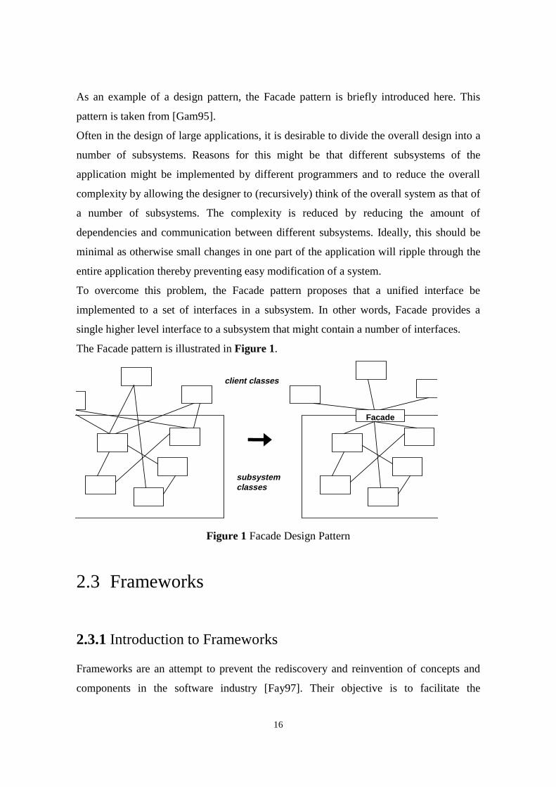
To overcome this problem, the Facade pattern proposes that a unified interface be
implemented to a set of interfaces in a subsystem. In other words, Facade provides a
single higher level interface to a subsystem that might contain a number of interfaces.
The Facade pattern is illustrated in Figure 1.
Facade
client classes
subsystemclasses
Figure 1 Facade Design Pattern
2.3 Frameworks
2.3.1 Introduction to Frameworks
Frameworks are an attempt to prevent the rediscovery and reinvention of concepts and
components in the software industry [Fay97]. Their objective is to facilitate the
17
development of applications in particular domains (eg. Graphical User Interfaces) or
business units (eg. manufacturing). In essence, frameworks are one approach to software
reuse.
A framework can be defined as a set of cooperating classes that make up a reusable
design for a specific class of software. It provides architectural guidance by partitioning
the design into abstract classes and defining their responsibilities and collaborations. A
developer customises the framework to a particular application by subclassing and
composing instances of framework classes [Gam95]. A framework dictates the
architecture of an application developed with it. It defines the application’s overall
structure, its partitioning into classes and objects, the key responsibilities of those classes
and objects, how they collaborate, and the thread of control.
Since a framework is more abstract than a finished application, in order to use a
framework to develop a particular application, the developer will need to extend
framework classes to implement application specific behaviour.
The objective of developing frameworks is to achieve both design and code reuse, as well
as shorter development times for applications, thereby reducing the cost of developing an
application. Frameworks leverage the domain knowledge of the framework developers,
thereby leaving the application developer to focus on specific application design issues
and problems.
Advantages of using frameworks are the already mentioned code and design reuse,
portability, rapid prototyping, and possibly performance customisation [Cam92].
Portability can be achieved through the separation of machine dependent parts of the
framework from machine independent parts. Rapid prototyping is achievable because the
framework provides code and design reuse, thus making it possible to quickly test various
implementations of a particular application built with the framework. Performance
customisation can be achieved through the use of one or another framework component
depending on the particular application.
2.3.2 Characteristics of Frameworks
Frameworks possess the following characteristics [Fay97]:
18
Modularity: Because a framework’s potentially unstable implementation details are
encapsulated by a stable interface, applications developed with the framework are not
exposed to changes in framework implementation and design, as long as the interface
remains stable.
Reusability: Since a framework encapsulates application domain specific knowledge and
prior effort of the framework developer, the application developer is able to reuse
common solutions to recurring application requirements, thereby saving development
time and improving the quality and reliability of the application.
Extensibility: Frameworks provide hook methods that allow the application developer to
extend the framework where needed.
Inversion of Control: Frameworks generally control the flow of control within an
application via event dispatching patterns. This is also known as the “Hollywood
Principle”, or “Don’t call us, we’ll call you”. When events occur, the framework’s
dispatcher reacts by invoking hook methods on pre-registered handler objects, which
perform application specific processing on the events.
2.3.3 Types of Framework
There are different ways of categorising frameworks. One classification is that of
whitebox versus blackbox frameworks [Joh88]. In a whitebox framework the application
developer adds methods to subclasses of one or more of the framework’s classes. These
methods implement application specific behaviour. Since these methods must be
designed and implemented as was intended by the designer of the superclasses, the
application developer needs to have an understanding of the framework’s
implementation.
In a blackbox framework, on the other hand, an application is created by composition
rather than inheritance, as in the whitebox framework. Various components may be
available as part of the framework and the application developer decides which
components are required to create a particular application. The application developer only
needs to know the public interface of the components, but not their implementations.
Blackbox frameworks have the advantage of being easier to learn, but have the
disadvantage of being less flexible, than whitebox frameworks. If there is a good
19
selection of components, the amount of programming required to create an application
with the framework will be much less than to do the same with a whitebox framework.
Thus, whitebox frameworks rely on inheritance whereas blackbox frameworks rely on
object composition. Of course, there is a continuous range from whitebox to blackbox
frameworks with some frameworks using both inheritance and object composition to
achieve application creation.
2.3.4 Frameworks in relation to other approaches to reuse
Other approaches to software reuse are design patterns, class libraries, and components
[Fay97]. These are related to frameworks in the following ways:
Design Patterns: Both design patterns and frameworks are approaches to software reuse.
However, they differ in a number of ways [Gam95]. Firstly, patterns are more abstract
than frameworks. Patterns enable design reuse whereas frameworks allow design and
code reuse. Patterns have to be implemented in code every time they are used. Secondly,
design patterns are smaller architectural elements than frameworks. This implies that
frameworks can contain a number of patterns, but never the other way around. Thirdly,
frameworks are specialised to a particular application domain. Design patterns, on the
other hand, can be used in any type of application.
Class libraries: Class libraries also are an approach to software reuse. Frameworks
extend the benefits of class libraries in the following ways: Firstly, class libraries
generally are less domain specific than frameworks. Generally they are lower level than
frameworks and thus don’t offer as high a level of reuse as frameworks. Frameworks, on
the other hand, can be viewed as semi-complete applications. Secondly, class libraries
don’t exhibit the inversion of control that frameworks do. Frameworks often make use of
class libraries. An example is the C++ Standard Template Library.
Components: Yet another approach to reuse, components are self-contained instances of
abstract data types [Fay97]. They can be plugged together to form complete applications.
Components are reused on the knowledge of their interfaces, not their implementations.
They can be reused without having to subclass from existing base classes. Thus they
represent blackbox reuse. Frameworks can be used to develop components, but
components can also be used to develop frameworks.
20
2.3.5 Examples of Frameworks
Numerous examples of frameworks exist. Here is a brief description of some of them:
Choices is an object-oriented operating system framework implemented in C++. It was
developed at the University of Illinois at Urbana-Champaign [Cam92, Joh91]. The
motivation behind the development of Choices was that different users of operating
systems have different needs. For example, some applications for operating systems
require large virtual address spaces, whereas others, such as real-time embedded systems
don’t require virtual memory at all. The Choices framework addresses this problem by
providing a family of operating systems that the user can tailor to specific requirements.
The Choices framework consists of a number of subframeworks, such as virtual memory,
process management, persistent storage, message passing, and device management.
These subframeworks are used to implement subsystems of the operating system. The
subframeworks provide abstract classes that are reused through inheritance, making
Choices a whitebox framework.
Smalltalk Model/View/Controller (MVC) is a framework for constructing Smalltalk-80
user interfaces [Gam95]. It consists of three types of object: the Model, the View, and the
Controller. The Model is the application object and the View is its screen representation.
Each Model can have multiple Views. If the Model’s data changes, the Views are notified
to update themselves. The Controller defines how the user interface reacts to user input.
An important aspect of MVC is that it contains a number of design patterns, such as
Observer, Composite, and Strategy. Thus it demonstrates how design patterns can be
used in the development of frameworks. Observer is a pattern that allows a one-to-many
dependency between objects to be created so that when one object changes its state, all
the other objects are notified and updated automatically. Composite is a pattern that
allows a tree-like structure of objects to be created. It allows clients to treat individual
objects and compositions of objects in the same way. Strategy is a pattern that allows
algorithms to be encapsulated by objects. It allows clients to freely interchange these
objects if the algorithm is to be varied. These patterns are described in more detail in
[Gam95].
Microsoft’s Microsoft Foundation Classes (MFC) is a framework for the development of
GUIs for the Microsoft Windows operating system [She96]. Its name is slightly
21
misleading, as it is in fact a framework, though parts of it can be used as a class library.
To create a Windows GUI application with MFC, the user needs to subclass from a
number of abstract classes. The relationships and constraints between these classes is
known as the document-view architecture, similar to the Model and View architecture in
MVC. To be able to create any but the most trivial applications, the user needs to have
some understanding of these relationships and constraints. Therefore, the MFC could also
be classified as a whitebox framework.
2.3.6 Strategies for developing Frameworks
Various methods or strategies for developing frameworks have been proposed. [Bec94]
[Dem96] [Kos] [Rob97]. Of these, the method that seems most inclusive of all
framework application domains, and pertains to the entire life cycle of framework
development is Evolving Frameworks, a pattern language for framework development. It
is described in more detail below.
2.3.6.1 A Pattern Language for developing Frameworks
One strategy, proposed by Roberts and Johnson, for developing frameworks, applies
design patterns to the problem of framework development [Rob97]. More specifically, a
pattern language for developing object-oriented frameworks is proposed. It is called
Evolving Frameworks. A pattern language can be described as a set of patterns that are
used together to solve a problem. Evolving Frameworks comprises of the following
patterns: Three Examples, Whitebox Framework, Blackbox Framework, Component
Library, Hot Spots, Pluggable Objects, Fine-grained Objects, Visual Builder, Language
Tools. The above sequence is the sequence in which the patterns generally will be applied
as the framework evolves, although this is not totally rigid.
Three Examples is the first and fundamental pattern in this pattern language. It argues
that it is impossible to design, from scratch, a framework without first having built at
least three applications of the type that the framework is intended to build. The
framework abstractions can then be determined from these examples.
The Whitebox Framework pattern proposes that the initial framework design, arrived at
by generalising from the classes in the individual applications, should be based on
22
inheritance. This framework subsequently could be changed into a Blackbox Framework,
but only when it is known which parts of the framework will consistently change across
applications and which parts remain constant.
Component Library proposes common classes that should be collected from the
application examples to form a component library.
Hot Spots proposes to separate code which changes between applications from code
which doesn’t. Ideally, the varying code is then encapsulated within objects. This
promotes reuse through composition of objects instead of subclassing from other classes.
The objective of the Pluggable Objects pattern is to avoid unnecessary subclassing when
the subclasses differ only in trivial ways. It achieves this by using parameters in the
instance creation protocol. In this way the subclass can be parameterised, in other words,
customised for its particular application.
Fine-Grained Objects proposes that objects be broken down into granularities as fine as
possible. The reason for this is that code duplication can be avoided in this way. If objects
are not broken down like this, some classes may end up encapsulating multiple
behaviours that could possibly vary independently. It is better to replace such a class with
a composition that recreates the behaviour of that class.
The creation of Pluggable Objects and Fine-Grained Objects leads to the ability to create
applications using composition. Therefore, the next step the design of the framework is to
reorganise the framework into a Blackbox Framework, which favours composition over
inheritance.
The Visual Builder pattern proposes a graphical program that lets the application
developer specify the objects of the application and how they are interconnected.
The last pattern in the language, Language Tools, suggests that specialised inspecting and
debugging tools be created for the framework.
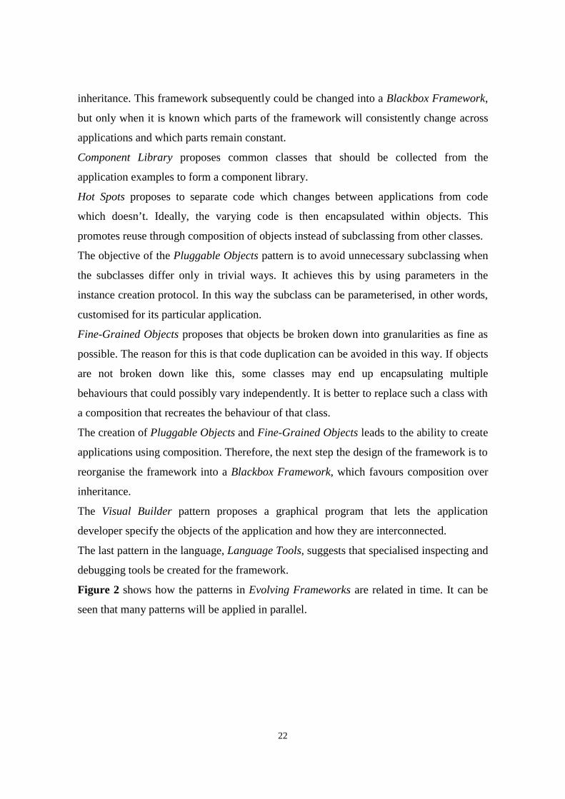
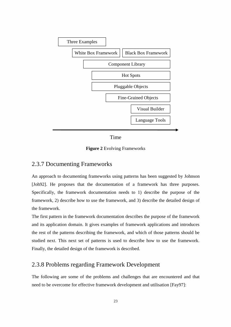
Figure 2 shows how the patterns in Evolving Frameworks are related in time. It can be
seen that many patterns will be applied in parallel.
23
Three Examples
White Box Framework Black Box Framework
Component Library
Hot Spots
Pluggable Objects
Fine-Grained Objects
Visual Builder
Language Tools
Time
Figure 2 Evolving Frameworks
2.3.7 Documenting Frameworks
An approach to documenting frameworks using patterns has been suggested by Johnson
[Joh92]. He proposes that the documentation of a framework has three purposes.
Specifically, the framework documentation needs to 1) describe the purpose of the
framework, 2) describe how to use the framework, and 3) describe the detailed design of
the framework.
The first pattern in the framework documentation describes the purpose of the framework
and its application domain. It gives examples of framework applications and introduces
the rest of the patterns describing the framework, and which of those patterns should be
studied next. This next set of patterns is used to describe how to use the framework.
Finally, the detailed design of the framework is described.
2.3.8 Problems regarding Framework Development
The following are some of the problems and challenges that are encountered and that
need to be overcome for effective framework development and utilisation [Fay97]:
24
Development effort: The effort and domain knowledge required for successful framework
development is higher than that required for application development in a particular
domain.
Learning curve: The learning curve involved in learning to use a particular framework is
often quite high. If only a few applications are ever going to be built using a framework,
the value of creating such a framework needs to be questioned, since in this case it might
not be a cost effective solution. Also, the suitability of a framework to building a
particular application may only become apparent after an amount of time has been
invested in learning the framework.
Integratability: If applications are built using more than one framework, compatibility
and integration problems may result. Specifically, the inversion of control principle of
frameworks could cause problems, as event loops in the frameworks may not be designed
to allow interoperability.
Maintainability: As application requirements change frequently, the requirements of
frameworks may change with them. Modifying and adapting a framework may prove
difficult for application developers since a deep understanding of framework internals
and relationships between framework components is essential.
Validation and defect removal: Debugging applications created with a framework may be
difficult. For example, since the flow of control is controlled by the framework, it may be
difficult to step through the application specific code of the application.
Efficiency: The generality and flexibility of a framework may reduce its efficiency.
2.4 CORBA and Frameworks
2.4.1 Introduction to CORBA Object Request Brokers
The Common Object Request Broker Architecture (CORBA) is a standard model for
distributed object-oriented systems. The CORBA standard forms part of the Object
Management Group’s (OMG) Object Management Architecture (OMA). The current
standard is CORBA 2.0. The purpose of the CORBA standard is to abstract distributed
25
object applications, which may run in a heterogeneous environment, away from
underlying networking protocols and transports. This facility is provided by Object
Request Brokers (ORBs), which lie at the heart of the OMA. An ORB allows a client to
deliver a request to a target object acting as a server, and it returns any responses to the
clients making the requests. The target object may reside in the same process, on the
same machine but in a different process, or on a different machine in a different process
somewhere on the network. The client-server relationship is only valid on a request basis.
A client object for one request could be a server object for another [Vin97].
CORBA consists of the following main elements:
ORB Core: The ORB core lets client objects transparently make requests to server
objects, and receive responses from them, whether they are in-process out-of-process, or
remote servers.
Interface Definition Language (IDL): The IDL enables interfaces between client and
server objects to be defined in a declarative, language independent manner. An interface
specifies the operations and types that the server object supports.
IDL Client Stub: The client stub acts as a local proxy for a remote server object. It
provides static interfaces to server object’s services. It is created by compiling the
interface definition using an IDL compiler.
IDL Server Skeleton: The server skeleton provides the static interface to each service
exported by the server. Like the client stubs, it is created by compiling the interface
definition using an IDL compiler.
Dynamic Invocation Interface (DII): The DII allows the client to discover at runtime the
server interface method to be invoked.
Dynamic Skeleton Invocation (DSI): The DSI is the server equivalent of the DII. It
provides a run-time binding mechanism for servers to handle incoming method calls for
components that do not have IDL-based compiled skeletons.
Object Adapter: The Object Adapter serves as the glue between object implementations
and the ORB core.
Interface Repository: The Interface Repository is a database that contains machine
readable versions of the IDL-defined interfaces.
26
Implementation Repository: The Implementation Repository contains information about
the classes supported by a server, which objects are instantiated, and their IDs.
ORB Interface: The ORB Interface contains APIs to some ORB services that may be
useful to an application.
Inter ORB Protocols: Inter ORB Protocols, such as GIOP and IIOP, allow ORBs from
different vendors to communicate with one another.
2.4.2 Some CORBA Application Scenarios
The objective of developing an ORB framework is to facilitate the implementation of
customised ORBs. Customised ORBs are ORBs that are tailored towards one or more
particular application scenarios. The following are examples of some such scenarios and
the issues that need to be addressed when developing ORBs, and therefore ORB
frameworks, for such scenarios.
2.4.2.1 Reliable Distributed Systems
A distributed system can be considered reliable if its behaviour is predictable despite
partial failures, asynchrony, and runtime reconfiguration of the system. Building reliable
distributed systems using CORBA is a priority in areas such as electronic commerce,
flight reservation systems, and real-time data feeds. It is, however, difficult to achieve for
a number of reasons. For example, because of partial failures of the system, the mean
time to failure of components in the distributed system decreases as the number of nodes
and communication links increases. Complex execution states can lead to situations such
as race conditions, deadlocks, and communication failures [Maf97].
Some approaches to implementing reliable distributed systems are message queues,
transaction processing monitors, and virtual synchrony. [Maf97] describes how these
approaches can be combined into an extended CORBA architecture for reliable systems.
2.4.2.2 Performance in CORBA Distributed Systems
Some distributed applications have specific Quality of Service (QoS) demands. Real time
systems, such as avionics or motion control systems, and constrained latency systems,
such as teleconferencing or telecommunications systems, fall into this category. Until
27
recently, the CORBA specification did not provide definitions for policies or mechanisms
for providing QoS guarantees in distributed applications. Recently A/V streams have
been added to the CORBA specification.
Existing ORBs exhibit significant runtime throughput and latency overheads. To be able
to construct real-time ORBs that can exhibit end to end QoS guarantees, the factors that
affect performance of ORBs need to be addressed. Some of these factors are [Sch97]:
specification of end to end QoS requirements, operating system and network resource
scheduling, communication protocols performance, request demultiplexing and
dispatching optimisation, memory management optimisation, and presentation layer
conversions.
2.4.2.3 Mobile Distributed Systems
Mobile distributed systems entail some of the following aspects: the frequent movement
of users and hosts, the scarcity of network and local computing resources available to the
mobile host, the possibility of disconnections. These lead to the following problems with
which mobile distributed systems are faced: frequent disconnections from the network,
widely varying bandwidths among wired and wireless links, limited CPU power and
device capacity on a mobile host, transient servers due to frequent handoff.
These problems lead to the following design guidelines for mobile distributed systems
[Che97]:
Minimum host-network coupling: Applications should be designed with minimum
coupling between the mobile host and the server as connections generally are unreliable.
Connection transparency: An application should be able to continue operating
transparently even if there are changes in the connection between mobile host and server,
such as handoff and disconnections.
Indirect interaction: To minimise interaction over the wireless link, user input processing
should be performed as close to the mobile host as possible.
Adaptive communication protocols: Because of variable bandwidth and heterogeneous
networks, communication protocols need to be adaptable.
Application partitioning: Because of unreliable connections, applications need to be
designed so that parts of them can be migrated to and run on the mobile host.
28
2.4.2.4 Developing a Framework for Customisable ORBs
The previous sections have introduced a number of topics which are fundamental to the
project, the development of a framework for customisable ORBs. The content of these
sections is to serve only as an introduction to some of the issues and approaches which
are relevant to this project.
The suggested approach to developing the framework is to apply the pattern language
Evolving Frameworks mentioned in the frameworks section. This pattern language begins
with the Three Examples pattern. Considering the limited amount of time allocated to this
project, it would obviously not be feasible to implement three separate ORBs, which may
cover various application scenarios, as is suggested by that pattern. On the other hand, a
deep, hands-on understanding of the application domain, customisable ORBs, is required
in order to attempt the design and implementation of an ORB framework. A possible
approach to overcome this problem would be to examine the implementations of a
number of different existing ORBs. ORBs exist for which the source code is publicly
available, and some of these are also well documented from a design point of view.
Some CORBA ORB implementations which focus on some of the different application
scenarios described above and for which source code is available are TAO, Electra, and
OmniORB.
OmniORB is a CORBA compliant ORB that has been developed by the Olivetti and
Oracle Research Laboratory. It is a plain, “vanilla” ORB, not geared towards any
particular application domain.
TAO is a CORBA compliant ORB that has been developed at the Department of
Computer Science, Washington University. It is an ORB aimed at applications with real-
time QoS requirements. It is designed to be extensible, maintainable, and dynamically
configurable. To achieve these objectives its design relies heavily on the use of design
patterns. Its design is well documented using these patterns in [Sch98].
Electra is a CORBA compliant ORB that is geared towards fault-tolerance and group
communication. It allows object groups, reliable multicast communication, and object
replication. It is designed to run on top of platforms such as Horus and Isis which are
low-level toolkits for the implementation of fault-tolerant distributed systems.
29
The first step will be to study the implementations of these three ORBs. This would
involve the study of both any documentation and literature that is available about them,
and also the source code which is publicly available. For the latter, an object-oriented
browsing tool, such as Takefive Software’s Sniff+, might be useful. Some of these tools
provide the ability to ‘reverse engineer’ source code to object notation, such as UML.
2.5 Summary
This chapter provided an introduction to some of the issues regarding the development of
an ORB framework. Object oriented design patterns were defined and an example of a
design pattern was provided. Object oriented frameworks in general were introduced and
some of their characteristics explained. Finally, the CORBA standard was briefly
introduced along with some possible application areas for distributed object applications.
30
Chapter 3
Analysis of existing Object RequestBrokers
3.1 Introduction
This chapter describes an analysis of three publicly available CORBA compliant
ORBs. The three ORBs are OmniORB, TAO, and Electra. OmniORB was developed
by the Olivetti and Oracle Research Laboratory. It is a basic ORB which is not geared
towards any particular application domain. TAO was developed at the Department of
Computer Science, Washington University. It is aimed at applications with real-time
Quality of Service requirements. Electra was developed by Silvano Maffeis while at
the University of Zurich. It is an ORB that is geared towards fault-tolerance and group
communication. It allows object groups, reliable multicast communication, and object
replication.
3.2 OmniORB
3.2.1 Introduction
The first ORB to be analysed was OmniORB2. OmniORB2 is an ORB that
implements version 2.0 of the Object Management Group’s CORBA specification. It
was developed by the Olivetti & Oracle Research Laboratory
31
(http://www.orl.co.uk). This section documents the investigation into the
implementation of OmniORB2.
3.2.2 Purpose of the analysis
The purpose of the analysis of the implementation of OmniORB2 was to gain insight
into how the architecture of a typical ORB is structured. Specifically, the internals of
OmniORB2 were to be analysed, in other words, those parts of OmniORB2 that
implement the CORBA specification but that are left to be implemented by the
different ORB vendors. Especially interesting was to determine whether any design
patterns were used. The use of these would facilitate the understanding of the design
of OmniORB2 and would be helpful in the subsequent design of an ORB framework.
They would also make it easier to document the design of OmniORB2.
3.2.3 Main features of OmniORB2
3.2.3.1 CORBA 2 compliancy
As stated in the introduction, OmniORB2 is an ORB that implements version 2.0 of
the OMG’s CORBA specification. It implements the Internet Inter-ORB Protocol
(IIOP) and uses this to communicate with other ORBs, and also uses it as its own
native protocol, i.e. for the communication between its objects residing in different
address spaces.
3.2.3.2 Platform support
OmniORB2 supports the following platforms: Sun Solaris, Digital Unix, HPUX, IBM
AIX, Linux, Windows NT, Windows 95, OpenVMS, ATMos, NextStep. Extensive
use of preprocessor directives is made in the source code to allow compilation for
these numerous supported platforms. This can make the source code quite difficult to
understand at times.
3.2.3.3 Missing features
OmniORB2 is not a complete implementation of the CORBA specification. Some
features are still missing:
32
• OmniORB2’s Basic Object Adapter (BOA) does not support dynamic server
activation and deactivation policies. It only supports the persistent server
activation policy.
• The Dynamic Invocation Interface is not supported.
• The Dynamic Skeleton Interface is not supported.
• OmniORB2 does not have its own Interface Repository.
3.2.4 Building and testing OmniORB2
The OmniORB2 distribution was downloaded from the Oracle & Olivetti Research
Laboratory’s web site. Although ready to run binaries are available to download,
OmniORB2 was downloaded in source code form and compiled and linked on site.
The download package comes as a zipped tar file which extracts into a directory tree.
The main parts of the package are:
3.2.4.1 The documentation
This consists of four documents which address the OmniORB2 itself, the OmniNames
naming service, which is an OmniORB2 implementation of the OMG’s COS Naming
Service Specification, OmniThread, which is a portable thread abstraction library used
by OmniORB2, and OmniORB utilities.
Of these documents, the principal one is the OmniORB2 manual. It is addressed at the
application developer who wants to know how to get started using OmniORB2. Some
of the examples that are provided with OmniORB2 are explained. The OmniORB2
API is explained as is the interface to the Basic Object Adapter (BOA). However, the
internal architecture of the ORB is not documented.
3.2.4.2 The source code
Source code is provided for OmniORB2 itself, the OmniThread library, the
OmniIDL2 compiler, which is the IDL compiler supplied with OmniORB2, a number
of examples, the OmniNames naming service, and the OmniORB2 utilities.
3.2.4.3 Makefiles
Makefiles are supplied to build the various binaries under the supported platforms. To
build the binaries under Unix requires GNUmake. To build the binaries under
Windows NT requires the gnu-win32 utilities from Cygnus Solutions.
33
3.2.4.4 Tools and methods used for analysing OmniORB
Initially OmniORB2 was built using the Sun C++ compiler and GNUmake under
Solaris 2.6. The three Echo examples, which are documented in Chapter 1 of the
OmniORB2 manual, were also built and executed as indicated. Because of a lack of
suitable debugging, analysis, and browsing tools under Unix, the OmniORB2 binaries
were rebuilt under Windows NT using Microsoft Visual C++ 5.0 and the Cygnus
Solutions gnu-win32 utilities. The advantage of examining OmniORB2 under
Windows NT was that the debugger which is supplied with Visual C++ could be used
to step through the application and ORB source code as an application was being
executed.
Next, the OmniORB2 source code was analysed using SNIFF+, a cross-platform
programming environment by TakeFive Software. SNIFF+ provides a number of
features that aid the comprehension of existing source code. Numerous tools, such as
an inheritance hierarchy browser, a cross reference browser, and an include browser,
are part of this environment and were found to be useful in the understanding of the
implementation of OmniORB2. SNIFF+ includes its own source code parser which
parses the source code of a project and builds its own internal representation of it. A
project therefore does not need to be compiled before the SNIFF+ tools can be used.
3.2.4.5 Problems encountered
Some problems were encountered in trying to analyse the architecture of OmniORB2.
Initially Solaris 5.6 was used as a platform for building the ORB and sample
applications. It was found that because of a lack of suitable tools it would prove
difficult to easily study the implementation of the ORB. The ORB was rebuilt under
Windows NT and this was found to be advantageous, especially in the area of
debugging.
A principal difficulty was the size of the source code. In the entire source code there
are over 360 classes and structures, not including nested classes. The source code is
very sparsely commented. There are no documents explaining the OmniORB2
architecture.
The large amount of preprocessor directives relating to macros and conditionally
compiled code, made the source code difficult to understand.
34
A problem noted with SNIFF+ is that it ignores nested classes, ie. those classes that
are declared within other class declarations. This meant that nested classes could not
be browsed as easily as others, but it was found not to be a big problem.
3.2.5 Overall architecture of the ORB
The following sections describe some of the principal components of the OmniORB2
ORB. C++ namespace is not used. Instead, some classes are nested within other
classes, for example, the class ORB is nested within the CORBA class, thus becoming
CORBA::ORB. The reason for this is that some of the supported compilers may not
have implemented the namespace keyword.
3.2.5.1 The ORB
The class that represents the ORB is CORBA::ORB. It provides the C++ mapping of
the CORBA::ORB interface. It also provides some internal OmniORB2 specific
functionality. An instance of this class is created in the function
CORBA::ORB_init(…) unless an instance of it already exists. This function is called
by both the object implementation and the client in order to obtain a pointer to the
ORB.
Another class, omniORB, provides the public API of OmniORB2’s extension to
CORBA. This API is intended to be used in application code. All its members and
methods are declared static and no actual instance of omniORB is ever created.
The public API provides features such as run-time tracing and diagnostic messages,
limiting the GIOP message size, and trapping internal errors.
3.2.5.2 The BOA
The class that represents the BOA is CORBA::BOA. It provides the C++ mapping of
the CORBA::BOA interface. Again, it also provides some internal OmniORB2
specific functionality. An instance of this class is created in the function
CORBA::ORB::BOA_init unless an instance of it already exists. As with the
function creating the ORB, this function is called by both the object implementation
and client in order to obtain a pointer to the BOA. After a call to BOA_init, the
BOA must be activated using impl_is_ready. This starts a thread listening on the
port on which IIOP requests are received. Objects can then be registered using the
function _obj_is_ready. This is a member function of the implementation
35
skeleton class and is called after the object is fully initialised. In the example below, it
is a member function of the class _sk_Echo.
3.2.5.3 Sample skeleton code generated by the IDL compiler
This section describes which classes are created by the IDL compiler when a sample
IDL file is compiled.
If the following example IDL interface
interface Echo {
string echoString (in string mesg);
}
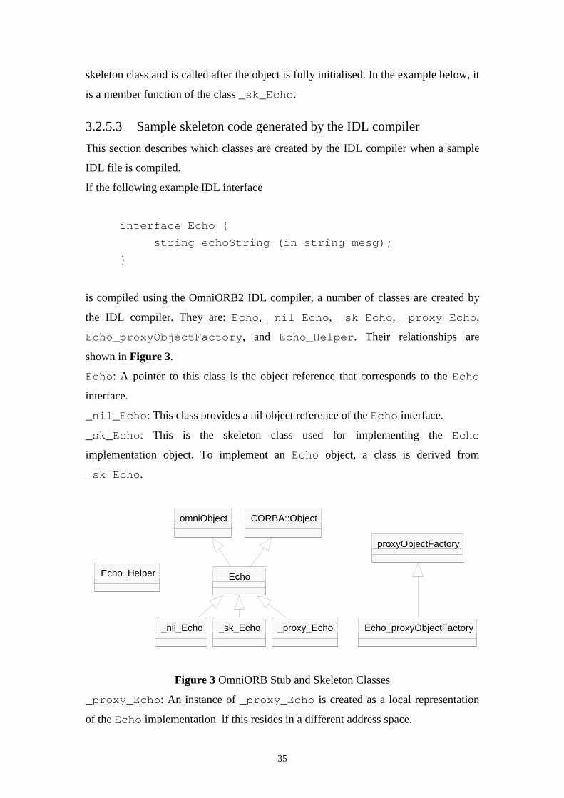
is compiled using the OmniORB2 IDL compiler, a number of classes are created by
the IDL compiler. They are: Echo, _nil_Echo, _sk_Echo, _proxy_Echo,
Echo_proxyObjectFactory, and Echo_Helper. Their relationships are
shown in Figure 3.
Echo: A pointer to this class is the object reference that corresponds to the Echo
interface.
_nil_Echo: This class provides a nil object reference of the Echo interface.
_sk_Echo: This is the skeleton class used for implementing the Echo
implementation object. To implement an Echo object, a class is derived from
_sk_Echo.
Figure 3 OmniORB Stub and Skeleton Classes
_proxy_Echo: An instance of _proxy_Echo is created as a local representation
of the Echo implementation if this resides in a different address space.
omniObject
Echo
_nil_Echo _sk_Echo _proxy_Echo
CORBA::Object
Echo_Helper
proxyObjectFactory
Echo_proxyObjectFactory
36
Echo_proxyObjectFactory: An instance of this class creates the
_proxy_Echo object on the client side if the Echo implementation resides in a
different address space.
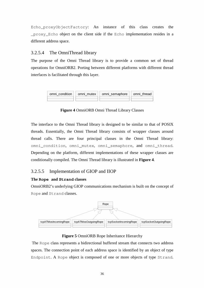
3.2.5.4 The OmniThread library
The purpose of the Omni Thread library is to provide a common set of thread
operations for OmniORB2. Porting between different platforms with different thread
interfaces is facilitated through this layer.
Figure 4 OmniORB Omni Thread Library Classes
The interface to the Omni Thread library is designed to be similar to that of POSIX
threads. Essentially, the Omni Thread library consists of wrapper classes around
thread calls. There are four principal classes in the Omni Thread library:
omni_condition, omni_mutex, omni_semaphore, and omni_thread.
Depending on the platform, different implementations of these wrapper classes are
conditionally compiled. The Omni Thread library is illustrated in Figure 4.
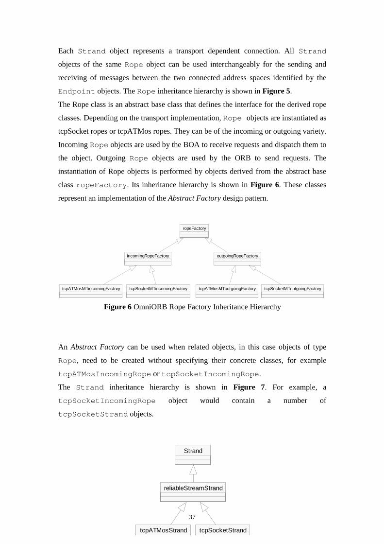
3.2.5.5 Implementation of GIOP and IIOP
The Rope and Strand classes
OmniORB2’s underlying GIOP communications mechanism is built on the concept of
Rope and Strand classes.
Figure 5 OmniORB Rope Inheritance Hierarchy
The Rope class represents a bidirectional buffered stream that connects two address
spaces. The connection point of each address space is identified by an object of type
Endpoint. A Rope object is composed of one or more objects of type Strand.
Rope
tcpATMosIncomingRope tcpATMosOutgoingRope tcpSocketIncomingRope tcpSocketOutgoingRope
omni_condition omni_semaphoreomni_mutex omni_thread
37
Each Strand object represents a transport dependent connection. All Strand
objects of the same Rope object can be used interchangeably for the sending and
receiving of messages between the two connected address spaces identified by the
Endpoint objects. The Rope inheritance hierarchy is shown in Figure 5.
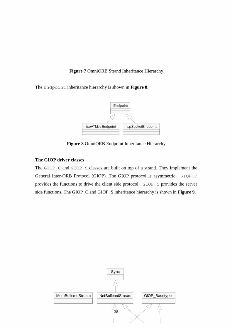
The Rope class is an abstract base class that defines the interface for the derived rope
classes. Depending on the transport implementation, Rope objects are instantiated as
tcpSocket ropes or tcpATMos ropes. They can be of the incoming or outgoing variety.
Incoming Rope objects are used by the BOA to receive requests and dispatch them to
the object. Outgoing Rope objects are used by the ORB to send requests. The
instantiation of Rope objects is performed by objects derived from the abstract base
class ropeFactory. Its inheritance hierarchy is shown in Figure 6. These classes
represent an implementation of the Abstract Factory design pattern.
Figure 6 OmniORB Rope Factory Inheritance Hierarchy
An Abstract Factory can be used when related objects, in this case objects of type
Rope, need to be created without specifying their concrete classes, for example
tcpATMosIncomingRope or tcpSocketIncomingRope.
The Strand inheritance hierarchy is shown in Figure 7. For example, a
tcpSocketIncomingRope object would contain a number of
tcpSocketStrand objects.
ropeFactory
incomingRopeFactory outgoingRopeFactory
tcpATMosMTincomingFactory tcpATMosMToutgoingFactorytcpSocketMTincomingFactory tcpSocketMToutgoingFactory
Strand
reliableStreamStrand
tcpATMosStrand tcpSocketStrand
38
Figure 7 OmniORB Strand Inheritance Hierarchy
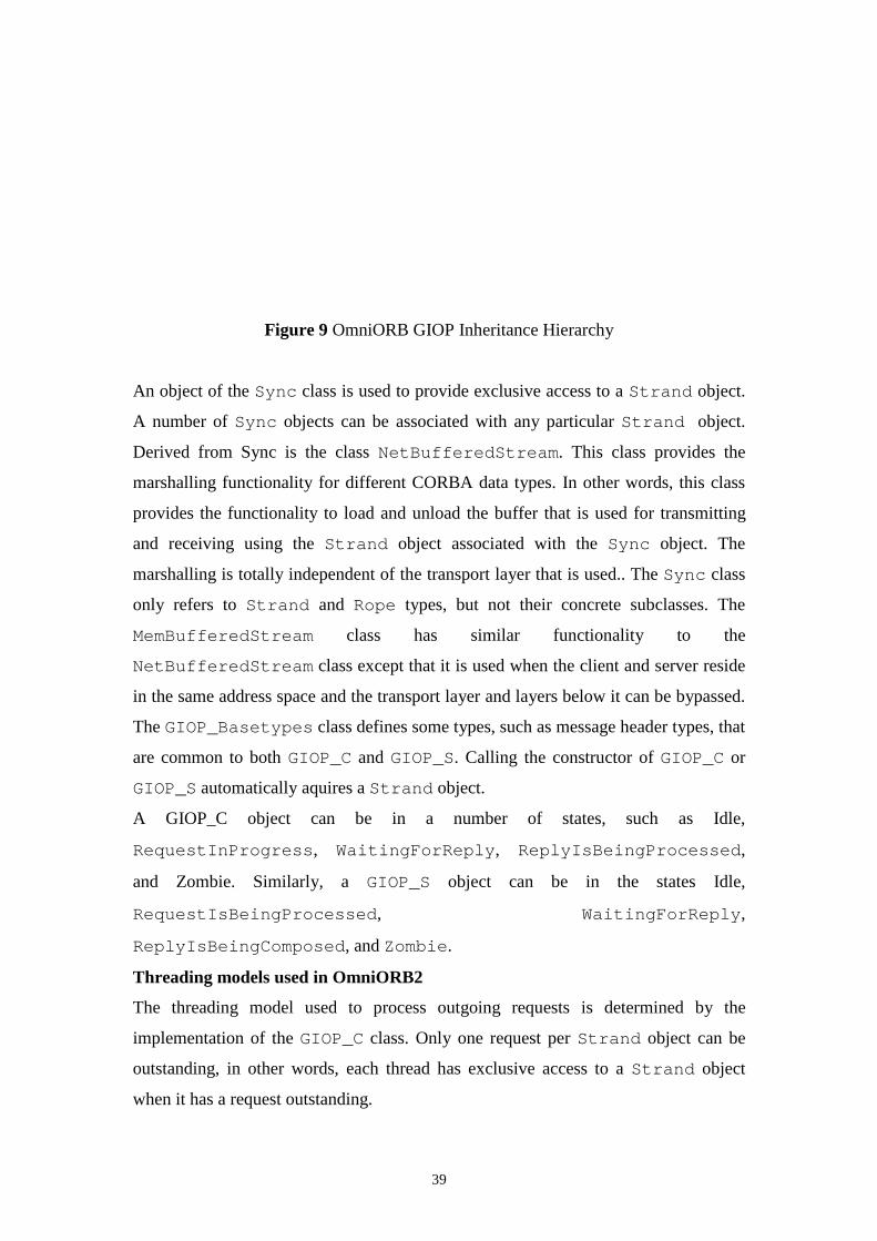
The Endpoint inheritance hierarchy is shown in Figure 8.
Figure 8 OmniORB Endpoint Inheritance Hierarchy
The GIOP driver classes
The GIOP_C and GIOP_S classes are built on top of a strand. They implement the
General Inter-ORB Protocol (GIOP). The GIOP protocol is asymmetric. GIOP_C
provides the functions to drive the client side protocol. GIOP_S provides the server
side functions. The GIOP_C and GIOP_S inheritance hierarchy is shown in Figure 9.
Endpoint
tcpATMosEndpoint tcpSocketEndpoint
Sync
NetBufferedStream GIOP_BasetypesMemBufferedStream
39
Figure 9 OmniORB GIOP Inheritance Hierarchy
An object of the Sync class is used to provide exclusive access to a Strand object.
A number of Sync objects can be associated with any particular Strand object.
Derived from Sync is the class NetBufferedStream. This class provides the
marshalling functionality for different CORBA data types. In other words, this class
provides the functionality to load and unload the buffer that is used for transmitting
and receiving using the Strand object associated with the Sync object. The
marshalling is totally independent of the transport layer that is used.. The Sync class
only refers to Strand and Rope types, but not their concrete subclasses. The
MemBufferedStream class has similar functionality to the
NetBufferedStream class except that it is used when the client and server reside
in the same address space and the transport layer and layers below it can be bypassed.
The GIOP_Basetypes class defines some types, such as message header types, that
are common to both GIOP_C and GIOP_S. Calling the constructor of GIOP_C or
GIOP_S automatically aquires a Strand object.
A GIOP_C object can be in a number of states, such as Idle,
RequestInProgress, WaitingForReply, ReplyIsBeingProcessed,
and Zombie. Similarly, a GIOP_S object can be in the states Idle,
RequestIsBeingProcessed, WaitingForReply,
ReplyIsBeingComposed, and Zombie.
Threading models used in OmniORB2
The threading model used to process outgoing requests is determined by the
implementation of the GIOP_C class. Only one request per Strand object can be
outstanding, in other words, each thread has exclusive access to a Strand object
when it has a request outstanding.
40
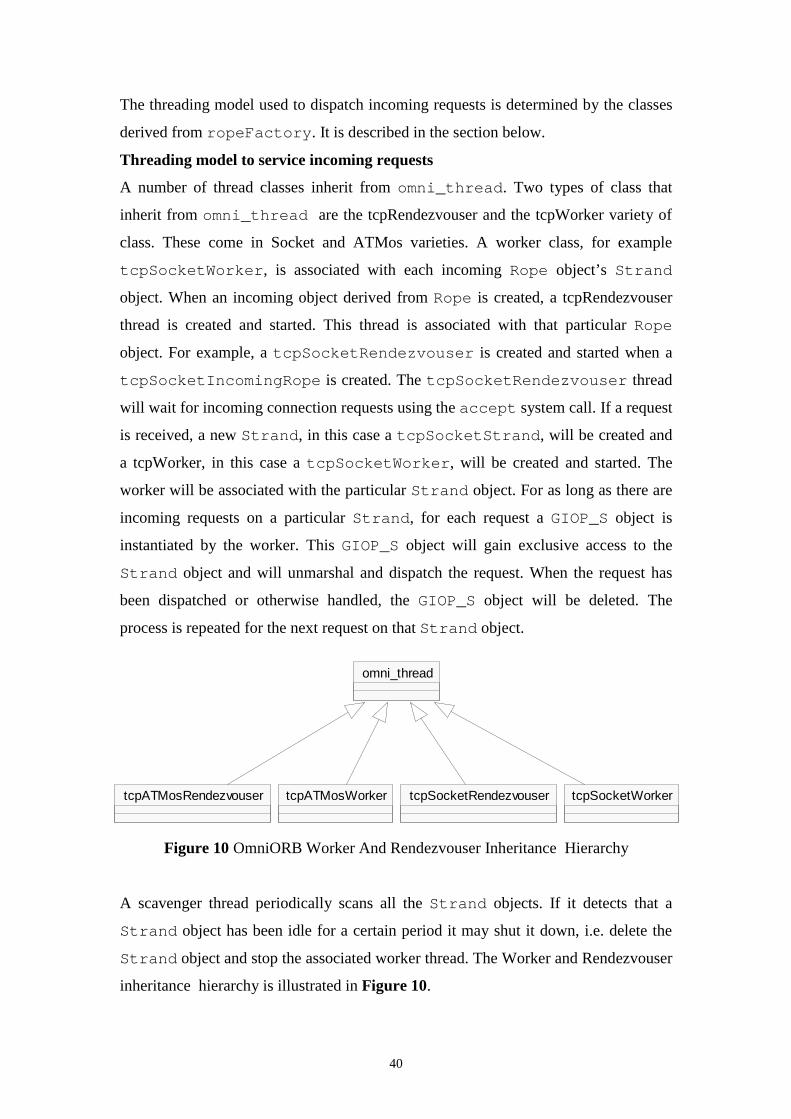
The threading model used to dispatch incoming requests is determined by the classes
derived from ropeFactory. It is described in the section below.
Threading model to service incoming requests
A number of thread classes inherit from omni_thread. Two types of class that
inherit from omni_thread are the tcpRendezvouser and the tcpWorker variety of
class. These come in Socket and ATMos varieties. A worker class, for example
tcpSocketWorker, is associated with each incoming Rope object’s Strand
object. When an incoming object derived from Rope is created, a tcpRendezvouser
thread is created and started. This thread is associated with that particular Rope
object. For example, a tcpSocketRendezvouser is created and started when a
tcpSocketIncomingRope is created. The tcpSocketRendezvouser thread
will wait for incoming connection requests using the accept system call. If a request
is received, a new Strand, in this case a tcpSocketStrand, will be created and
a tcpWorker, in this case a tcpSocketWorker, will be created and started. The
worker will be associated with the particular Strand object. For as long as there are
incoming requests on a particular Strand, for each request a GIOP_S object is
instantiated by the worker. This GIOP_S object will gain exclusive access to the
Strand object and will unmarshal and dispatch the request. When the request has
been dispatched or otherwise handled, the GIOP_S object will be deleted. The
process is repeated for the next request on that Strand object.
Figure 10 OmniORB Worker And Rendezvouser Inheritance Hierarchy
A scavenger thread periodically scans all the Strand objects. If it detects that a
Strand object has been idle for a certain period it may shut it down, i.e. delete the
Strand object and stop the associated worker thread. The Worker and Rendezvouser
inheritance hierarchy is illustrated in Figure 10.
omni_thread
tcpATMosRendezvouser tcpATMosWorker tcpSocketRendezvouser tcpSocketWorker
41
3.2.6 Conclusion
With some initial delays in setting up OmniORB2 and the relatively brief period
allocated to its study, it was found that only an overall view of the internals of
OmniORB2 could be obtained and that most areas could not be studied in great detail.
However, the study has been useful in that it has provided a general insight into the
workings of an ORB and that it offers areas of interest, for example, the
implementation of certain classes, to be revisited and studied in greater detail at a
later stage of the project, if necessary.
3.3 TAO
3.3.1 Introduction
In the study of the implementation of a number of CORBA compliant public domain
ORBs, TAO (The ACE ORB) was chosen to be the second ORB to be examined.
TAO is a CORBA 2.0 compliant ORB, aimed at high-performance, real-time
applications. It extends the OMG CORBA specification by allowing applications to
specify Quality of Service (QoS) requirements. It was developed by the Distributed
Object Computing Group at Washington University
(www.cs.wustl.edu/~schmidt/TAO.html). This report documents the
investigation into the implementation of TAO.
3.3.2 Purpose of the analysis
The purpose of the analysis of the implementation of TAO was similar to that of
OmniORB2. In addition, an objective of the study was to gain insight into how an
ORB aimed at the high-performance, realtime application domain might be
implemented, and how it would differ from a standard ORB.
3.3.3 Main features of TAO
42
3.3.3.1 Realtime ORB core
TAO’s realtime ORB core is based on the Adaptive Communication Environment
(ACE) framework. It is designed to provide a number of threading models, such as
thread-per-connection, or reactor-per-thread-priority. The TAO ORB core uses the
Realtime Inter ORB Protocol (RIOP), which is based on IIOP, for interORB
communication.
3.3.3.2 Optimised Object Adapter
The TAO Object Adapter is responsible for demultiplexing and dispatching client
requests to servant operations. In conventional ORB systems, demultiplexing takes
place on a number of layers. TAO’s Object Adapter uses demultiplexing keys
assigned by the ORB to clients to achieve delayered demultiplexing.
3.3.3.3 Realtime IDL (RIDL) QoS specification
TAO provides an IDL interface for applicatins to specify their realtime resource
requirements. This information is passed to TAO’s Realtime Scheduling Service. The
TAO Realtime Scheduling Service performs offline feasability scheduling analysis to
determine whether there are enough CPU resources to perform all requested tasks
which the application has registered with the Realtime Scheduling Service repository.
The Scheduling Services also perform thread priority assignment during this offline
analysis. This information is used by the ORB core at runtime to assign thread
priorities. At runtime, requests are queued according to their priorities.
3.3.3.4 IDL compiler optimisations
Because the conversion of typed operation parameters from higher-level to lower-
level representations (marshaling) and vice versa (demarshaling) can be a bottleneck,
the TAO IDL compiler provides a number of optimising features. For example, either
interpreted or compiled IDL stubs and skeletons can be linked into the application.
Interpreted code is slower, but smaller in size, whereas compiled code is faster, but
bigger in size.
3.3.3.5 Memory Management Optimisations
43
For efficiency reasons, TAO tries to keep dynamic memory management to a
minimum. For example, it uses a “zero-copy” buffer management system when
sending and receiving client requests to and from the network.
3.3.3.6 Platform support
Platforms supported by TAO are Windows NT, Solaris, VxWorks, and Linux.
3.3.4 Building and testing TAO
The TAO distribution kit was downloaded from the TAO website. It includes the
ACE framework distribution. Uncompressed, the package is about 40MB in size.
Both ACE and TAO were built from the source code using GNUmake and the Sun
C++ compiler under Solaris 2.6.
3.3.4.1 The documentation
The design of both ACE and TAO is very well documented. A number of papers
exist, outlining the design of ACE and TAO, patterns used in their design, and
performance measurements and comparisons with a number of other ORBs. Most of
the information about the design of TAO was obtained from these papers. They can
be downloaded from the TAO website.
3.3.5 Overall Architecture of the TAO ORB
TAO is a CORBA compliant Object Request Broker that is aimed at real time
distributed applications. It is designed to deliver end-to-end Quality of Service (QoS)
guarantees. QoS guarantees allow applications to meet certain timing constraints,
which, if they weren’t met, would render useless the application built on top of the
ORB.
3.3.5.1 The ACE Framework
TAO is built using the ACE (Adaptive Communication Environment) framework.
ACE is an object oriented toolkit for the development of network and communication
applications. It is written in C++ and is targeted for applications on Unix and Win32
platforms. It facilitates the development of object oriented applications that use
interprocess communication, event demultiplexing, explicit dynamic linking, and
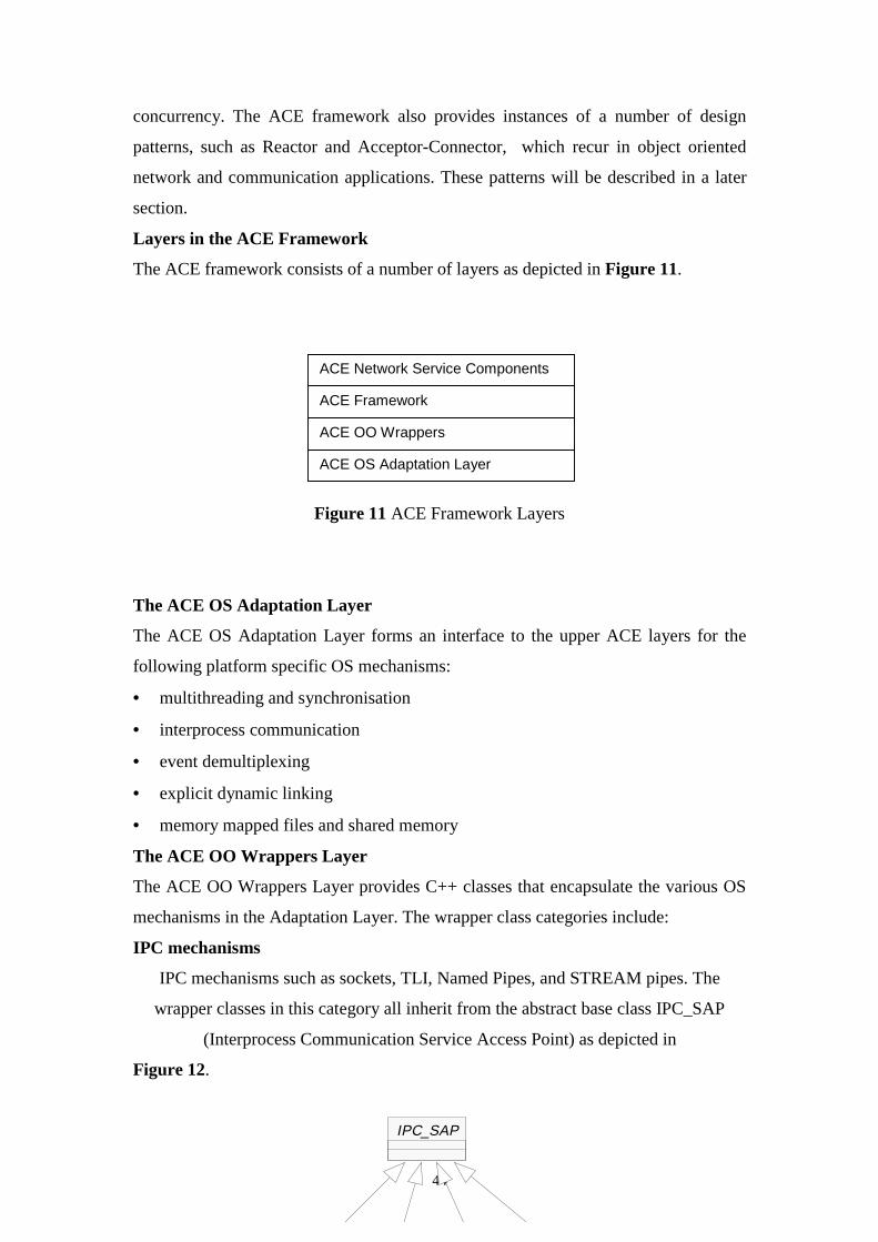
44
concurrency. The ACE framework also provides instances of a number of design
patterns, such as Reactor and Acceptor-Connector, which recur in object oriented
network and communication applications. These patterns will be described in a later
section.
Layers in the ACE Framework
The ACE framework consists of a number of layers as depicted in Figure 11.
Figure 11 ACE Framework Layers
The ACE OS Adaptation Layer
The ACE OS Adaptation Layer forms an interface to the upper ACE layers for the
following platform specific OS mechanisms:
• multithreading and synchronisation
• interprocess communication
• event demultiplexing
• explicit dynamic linking
• memory mapped files and shared memory
The ACE OO Wrappers Layer
The ACE OO Wrappers Layer provides C++ classes that encapsulate the various OS
mechanisms in the Adaptation Layer. The wrapper class categories include:
IPC mechanisms
IPC mechanisms such as sockets, TLI, Named Pipes, and STREAM pipes. The
wrapper classes in this category all inherit from the abstract base class IPC_SAP
(Interprocess Communication Service Access Point) as depicted in
Figure 12.
ACE Network Service Components
ACE Framework
ACE OO Wrappers
ACE OS Adaptation Layer
IPC_SAP
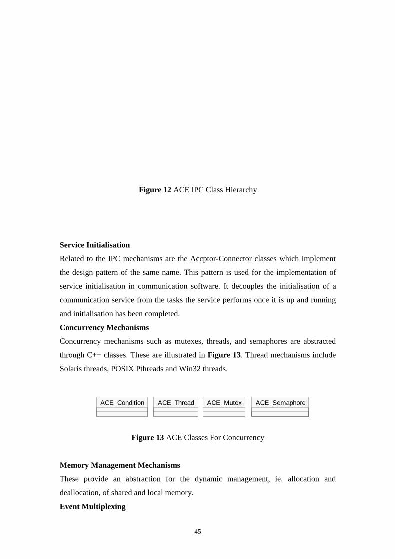
45
Figure 12 ACE IPC Class Hierarchy
Service Initialisation
Related to the IPC mechanisms are the Accptor-Connector classes which implement
the design pattern of the same name. This pattern is used for the implementation of
service initialisation in communication software. It decouples the initialisation of a
communication service from the tasks the service performs once it is up and running
and initialisation has been completed.
Concurrency Mechanisms
Concurrency mechanisms such as mutexes, threads, and semaphores are abstracted
through C++ classes. These are illustrated in Figure 13. Thread mechanisms include
Solaris threads, POSIX Pthreads and Win32 threads.
Figure 13 ACE Classes For Concurrency
Memory Management Mechanisms
These provide an abstraction for the dynamic management, ie. allocation and
deallocation, of shared and local memory.
Event Multiplexing
ACE_Condition ACE_Thread ACE_Mutex ACE_Semaphore
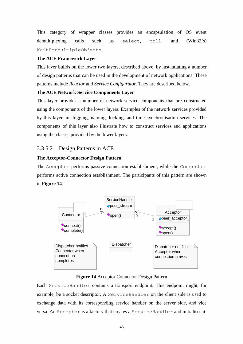
46
This category of wrapper classes provides an encapsulation of OS event
demultiplexing calls such as select, poll, and (Win32’s)
WaitForMultipleObjects.
The ACE Framework Layer
This layer builds on the lower two layers, described above, by instantiating a number
of design patterns that can be used in the development of network applications. These
patterns include Reactor and Service Configurator. They are described below.
The ACE Network Service Components Layer
This layer provides a number of network service components that are constructed
using the components of the lower layers. Examples of the network services provided
by this layer are logging, naming, locking, and time synchronisation services. The
components of this layer also illustrate how to construct services and applications
using the classes provided by the lower layers.
3.3.5.2 Design Patterns in ACE
The Acceptor-Connector Design Pattern
The Acceptor performs passive connection establishment, while the Connector
performs active connection establishment. The participants of this pattern are shown
in Figure 14.
Figure 14 Acceptor Connector Design Pattern
Each ServiceHandler contains a transport endpoint. This endpoint might, for
example, be a socket descriptor. A ServiceHandler on the client side is used to
exchange data with its corresponding service handler on the server side, and vice
versa. An Acceptor is a factory that creates a ServiceHandler and initialises it.
ServiceHandler
peer_stream
open()Connector
connect()complete()
Acceptor
peer_acceptor_
accept()open()
Dispatcher
1n1
n
Dispatcher notifies Connector when connection completes
Dispatcher notifies Acceptor when connection arrives
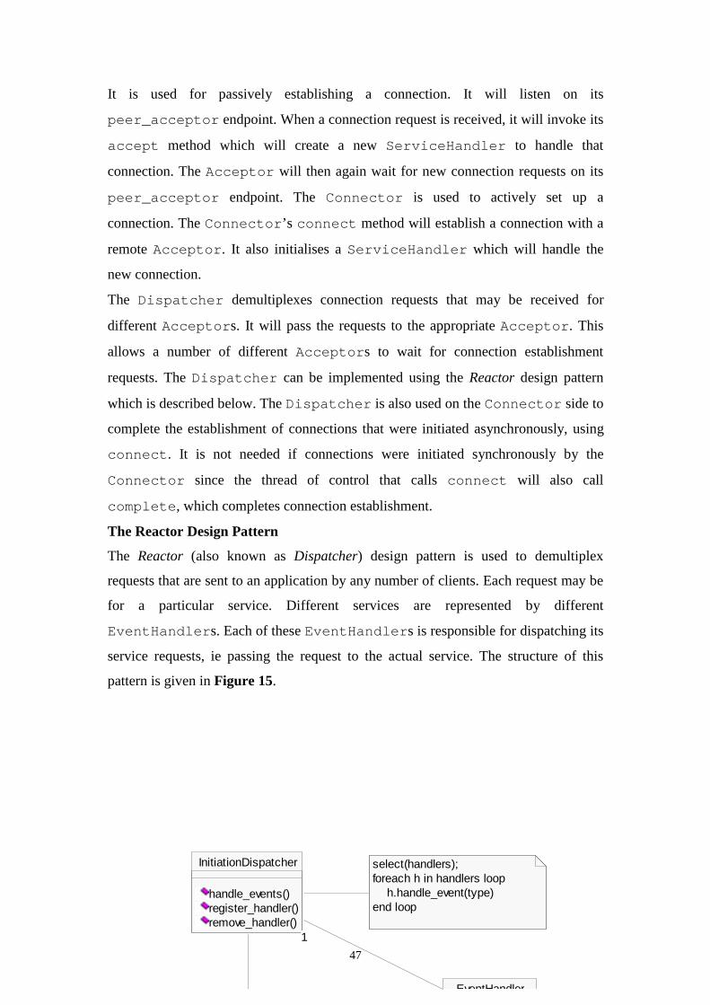
47
It is used for passively establishing a connection. It will listen on its
peer_acceptor endpoint. When a connection request is received, it will invoke its
accept method which will create a new ServiceHandler to handle that
connection. The Acceptor will then again wait for new connection requests on its
peer_acceptor endpoint. The Connector is used to actively set up a
connection. The Connector’s connect method will establish a connection with a
remote Acceptor. It also initialises a ServiceHandler which will handle the
new connection.
The Dispatcher demultiplexes connection requests that may be received for
different Acceptors. It will pass the requests to the appropriate Acceptor. This
allows a number of different Acceptors to wait for connection establishment
requests. The Dispatcher can be implemented using the Reactor design pattern
which is described below. The Dispatcher is also used on the Connector side to
complete the establishment of connections that were initiated asynchronously, using
connect. It is not needed if connections were initiated synchronously by the
Connector since the thread of control that calls connect will also call
complete, which completes connection establishment.
The Reactor Design Pattern
The Reactor (also known as Dispatcher) design pattern is used to demultiplex
requests that are sent to an application by any number of clients. Each request may be
for a particular service. Different services are represented by different
EventHandlers. Each of these EventHandlers is responsible for dispatching its
service requests, ie passing the request to the actual service. The structure of this
pattern is given in Figure 15.
InitiationDispatcher
handle_events()register_handler()remove_handler()
select(handlers);foreach h in handlers loop h.handle_event(type)end loop
EventHandler
11
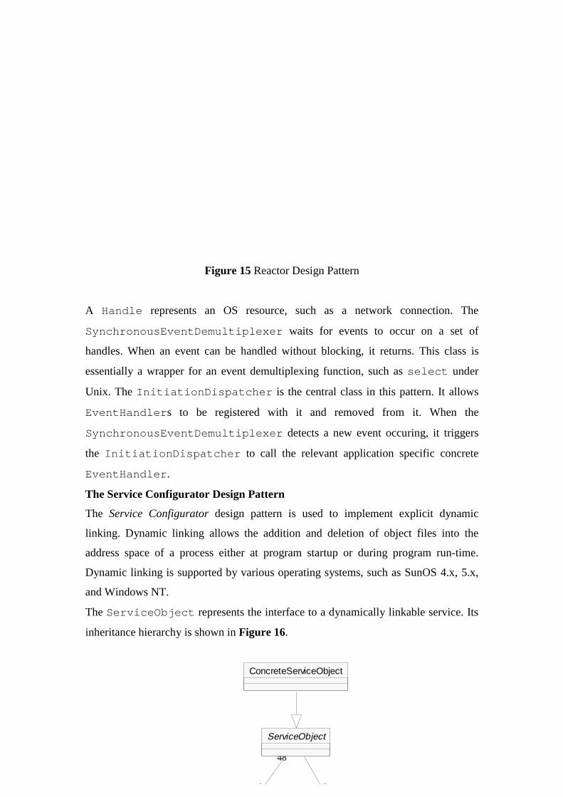
48
Figure 15 Reactor Design Pattern
A Handle represents an OS resource, such as a network connection. The
SynchronousEventDemultiplexer waits for events to occur on a set of
handles. When an event can be handled without blocking, it returns. This class is
essentially a wrapper for an event demultiplexing function, such as select under
Unix. The InitiationDispatcher is the central class in this pattern. It allows
EventHandlers to be registered with it and removed from it. When the
SynchronousEventDemultiplexer detects a new event occuring, it triggers
the InitiationDispatcher to call the relevant application specific concrete
EventHandler.
The Service Configurator Design Pattern
The Service Configurator design pattern is used to implement explicit dynamic
linking. Dynamic linking allows the addition and deletion of object files into the
address space of a process either at program startup or during program run-time.
Dynamic linking is supported by various operating systems, such as SunOS 4.x, 5.x,
and Windows NT.
The ServiceObject represents the interface to a dynamically linkable service. Its
inheritance hierarchy is shown in Figure 16.
ServiceObject
ConcreteServiceObject
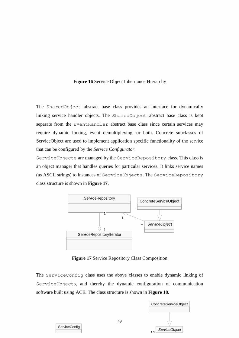
49
Figure 16 Service Object Inheritance Hierarchy
The SharedObject abstract base class provides an interface for dynamically
linking service handler objects. The SharedObject abstract base class is kept
separate from the EventHandler abstract base class since certain services may
require dynamic linking, event demultiplexing, or both. Concrete subclasses of
ServiceObject are used to implement application specific functionality of the service
that can be configured by the Service Configurator.
ServiceObjects are managed by the ServiceRepository class. This class is
an object manager that handles queries for particular services. It links service names
(as ASCII strings) to instances of ServiceObjects. The ServiceRepository
class structure is shown in Figure 17.
Figure 17 Service Repository Class Composition
The ServiceConfig class uses the above classes to enable dynamic linking of
ServiceObjects, and thereby the dynamic configuration of communication
software built using ACE. The class structure is shown in Figure 18.
ConcreteServiceObject
ServiceObject
ServiceRepository
1
*
ServiceRepositoryIterator1
1
1
11
*
ConcreteServiceObject
ServiceConfigServiceObject
+n
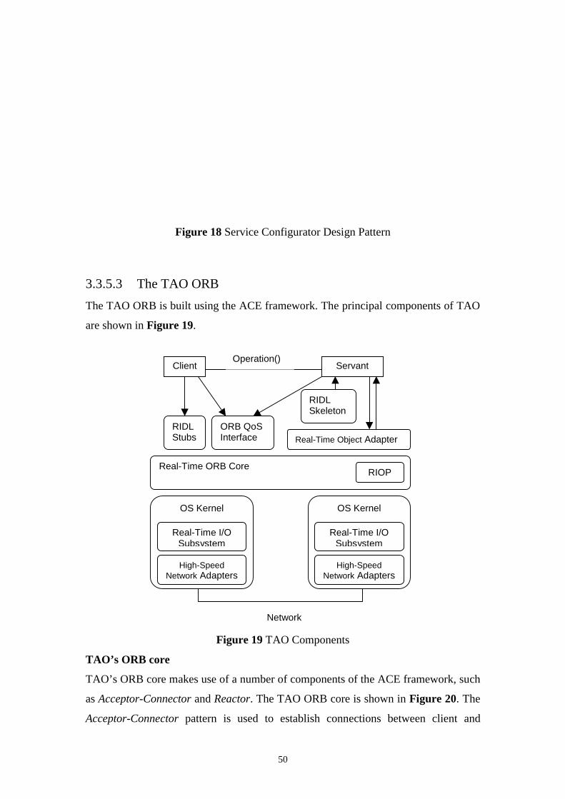
50
Figure 18 Service Configurator Design Pattern
3.3.5.3 The TAO ORB
The TAO ORB is built using the ACE framework. The principal components of TAO
are shown in Figure 19.
Figure 19 TAO Components
TAO’s ORB core
TAO’s ORB core makes use of a number of components of the ACE framework, such
as Acceptor-Connector and Reactor. The TAO ORB core is shown in Figure 20. The
Acceptor-Connector pattern is used to establish connections between client and
Client ServantOperation()
RIDLStubs
ORB QoSInterface
RIDLSkeleton
Real-Time Object Adapter
Real-Time ORB CoreRIOP
OS Kernel
High-SpeedNetwork Adapters
Real-Time I/OSubsystem
OS Kernel
High-SpeedNetwork Adapters
Real-Time I/OSubsystem
Network

51
server, with the Reactor taking the role of dispatcher on the Acceptor (server) side. On
the client side, the Strategy_Connector caches connections to the server while
on the server side the Reactor detects new incoming connections and notifies the
Strategy_Acceptor, which associates the new connection with a
Connection_Handler. The acceptors and connectors in the ORB core are called
Strategy_Acceptor and Strategy_Connector since they make use of the
Strategy design pattern. This allows them to use different strategies for connection
management and handler concurrency. For example, the Strategy_Connector can use
thread-specific cached connections or process-wide cached connections.
Figure 20 TAO ORB Core
TAO’s Real-Time Object Adapter
TAO’s real-time Object Adapter associates a servant with the ORB and demultiplexes
incoming client requests to the servant. It can be configured, using the Strategy
pattern, to dispatch client requests according to one of a number of real-time
scheduling policies. The currently available strategies are Real-Time Upcall (RTU)
GIOP Handler
StrategyConnector
ConnectionHandler
CachedConnectStrategy
+0-n
ConnectionHandler
ConnectionHandler
ConnectionHandler
StrategyAcceptor
Reactor
StrategyAcceptor
Reactor
ORB Core
Client
connect( accept(
Create &Request/Respons
operation() dispatch()
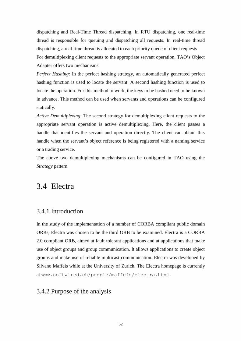
52
dispatching and Real-Time Thread dispatching. In RTU dispatching, one real-time
thread is responsible for queuing and dispatching all requests. In real-time thread
dispatching, a real-time thread is allocated to each priority queue of client requests.
For demultiplexing client requests to the appropriate servant operation, TAO’s Object
Adapter offers two mechanisms.
Perfect Hashing: In the perfect hashing strategy, an automatically generated perfect
hashing function is used to locate the servant. A second hashing function is used to
locate the operation. For this method to work, the keys to be hashed need to be known
in advance. This method can be used when servants and operations can be configured
statically.
Active Demultiplexing: The second strategy for demultiplexing client requests to the
appropriate servant operation is active demultiplexing. Here, the client passes a
handle that identifies the servant and operation directly. The client can obtain this
handle when the servant’s object reference is being registered with a naming service
or a trading service.
The above two demultiplexing mechanisms can be configured in TAO using the
Strategy pattern.
3.4 Electra
3.4.1 Introduction
In the study of the implementation of a number of CORBA compliant public domain
ORBs, Electra was chosen to be the third ORB to be examined. Electra is a CORBA
2.0 compliant ORB, aimed at fault-tolerant applications and at applications that make
use of object groups and group communication. It allows applications to create object
groups and make use of reliable multicast communication. Electra was developed by
Silvano Maffeis while at the University of Zurich. The Electra homepage is currently
at www.softwired.ch/people/maffeis/electra.html.
3.4.2 Purpose of the analysis
53
The purpose of the analysis of Electra was similar to that of OmniORB2. In addition,
an objective of the study was to gain insight into how an ORB aimed at fault tolerant,
and object group based applications might be implemented, and how it would differ
from a standard ORB.
3.4.3 Main features of Electra
3.4.3.1 CORBA compliancy
Electra is based on the CORBA 2.0 specification. The current version of Electra is
2.0b. It includes:
• A CORBA IDL compiler
• A binding for the C++ programming language
• A Basic Object Adapter (BOA) that supports object groups and object replication
• An ORB, a Static Invocation Interface (SII), and a Dynamic Invocation
Interface(DII)
• A fault tolerant COSS Name Server
• Piranha, the Electra remote activation and network management utility
• A Tcl/Tk interface to the DII (experimental)
• An Internet ORB gateway (experimental)
It does not include
• An Interface or Implementation Repository
3.4.3.2 Platform support
Electra can be built and configured on Solaris, SunOS, and HPUX. It requires that a
toolkit for reliable distributed systems is installed and running on the same machine.
Toolkits currently supported are Horus, Isis, and Ensemble.
3.4.3.3 Facility for object groups
Electra provides the facility to create object groups , to perform object replication, and
to perform reliable multicast communication. To achieve this, Electra is based on
toolkits for the implementation of reliable distributed systems. Examples of these are
Horus, Isis, and Ensemble. An object group is simply the combination of a number of

54
network objects. They are treated as a unit. Reliable multicast communication ensures
that invocations aimed at an object group will be received by each object
implementation which is part of that object group. The provision for object groups
allows Electra to be used for a number of application scenarios including fault-
tolerance, load sharing, caching, and mobility.
To allow applications to create object groups and to join and remove objects from
object groups, a number of operations were added to the BOA interface. These are
create_group, join, leave, destroy_group, get_state, set_state, view_change.
A detailed description of the use of object groups in Electra can be found in [Maf95a]
and [Maf95b].
3.4.4 Overall architecture of the Electra ORB
The Electra ORB is based on the Electra Object Model (EOM) [Maf95b]. The EOM
enhances CORBA by allowing objects to be grouped into object-groups. Object
groups can be named as a single unit. Applications can bind object references to both
individual objects and object groups, using the same expressions. Communication to
object groups is by reliable multicast, which ensures that an operation is received by
all members of a group. Communication can take place in transparent or
nontransparent mode. In transparent mode only one response is received after an
invocation on an object group. In nontransparent mode, each object group member’s
response can be accessed by clients. Object invocations can be performed
asynchronously, synchronously, or deferred-synchronously.
To implement reliable multicast and group communication, Electra can make use of
existing distributed programming libraries such as Horus and Isis. Their use avoids
having to reimplement much functionality specifically for Electra. Some possible
Electra configurations for a number of different distributed programming libraries or
operating systems (Horus, Isis, and Chorus) are shown in Figure 21.
Electra Abstractions:Object Groups, Remote Method Calls, Class Libraries, etc.
Virtual Machine Interface:Threads, Reliable Multicast, Ordering of Events, etc.
Horus Adapter Isis Adapter ChorusAdapter
Reliable Mcast,Ordering,
Unix Adapter
ReliableMcast,Horus Toolkit Isis Toolkit
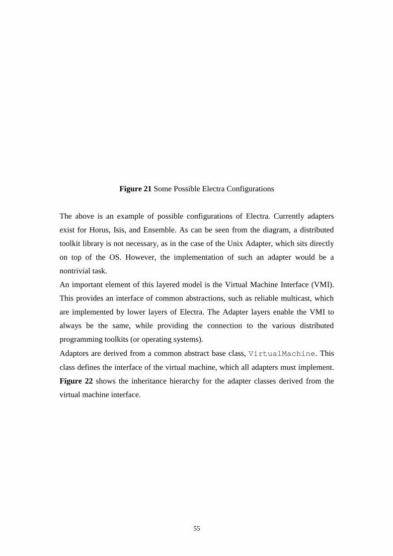
55
Figure 21 Some Possible Electra Configurations
The above is an example of possible configurations of Electra. Currently adapters
exist for Horus, Isis, and Ensemble. As can be seen from the diagram, a distributed
toolkit library is not necessary, as in the case of the Unix Adapter, which sits directly
on top of the OS. However, the implementation of such an adapter would be a
nontrivial task.
An important element of this layered model is the Virtual Machine Interface (VMI).
This provides an interface of common abstractions, such as reliable multicast, which
are implemented by lower layers of Electra. The Adapter layers enable the VMI to
always be the same, while providing the connection to the various distributed
programming toolkits (or operating systems).
Adaptors are derived from a common abstract base class, VirtualMachine. This
class defines the interface of the virtual machine, which all adapters must implement.
Figure 22 shows the inheritance hierarchy for the adapter classes derived from the
virtual machine interface.
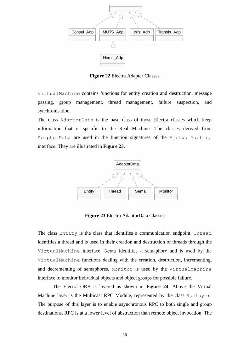
56
Figure 22 Electra Adapter Classes
VirtualMachine contains functions for entity creation and destruction, message
passing, group management, thread management, failure suspection, and
synchronisation.
The class AdaptorData is the base class of those Electra classes which keep
information that is specific to the Real Machine. The classes derived from
AdaptorData are used in the function signatures of the VirtualMachine
interface. They are illustrated in Figure 23.
Figure 23 Electra AdaptorData Classes
The class Entity is the class that identifies a communication endpoint. Thread
identifies a thread and is used in their creation and destruction of threads through the
VirtualMachine interface. Sema identifies a semaphore and is used by the
VirtualMachine functions dealing with the creation, destruction, incrementing,
and decrementing of semaphores. Monitor is used by the VirtualMachine
interface to monitor individual objects and object groups for possible failure.
The Electra ORB is layered as shown in Figure 24. Above the Virtual
Machine layer is the Multicast RPC Module, represented by the class RpcLayer.
The purpose of this layer is to enable asynchronous RPC to both single and group
destinations. RPC is at a lower level of abstraction than remote object invocation. The
AdaptorData
Entity Thread Sema Monitor
Consul_Adp MUTS_Adp Isis_Adp Transis_Adp
Horus_Adp
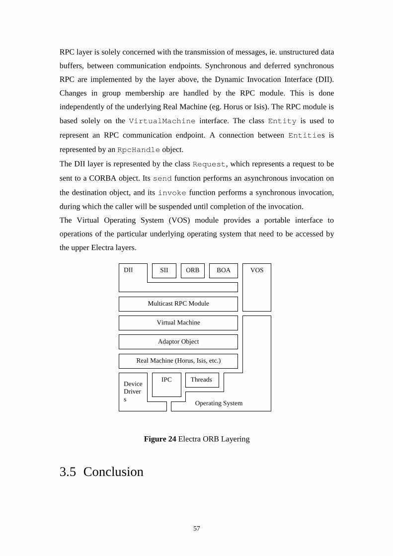
57
RPC layer is solely concerned with the transmission of messages, ie. unstructured data
buffers, between communication endpoints. Synchronous and deferred synchronous
RPC are implemented by the layer above, the Dynamic Invocation Interface (DII).
Changes in group membership are handled by the RPC module. This is done
independently of the underlying Real Machine (eg. Horus or Isis). The RPC module is
based solely on the VirtualMachine interface. The class Entity is used to
represent an RPC communication endpoint. A connection between Entities is
represented by an RpcHandle object.
The DII layer is represented by the class Request, which represents a request to be
sent to a CORBA object. Its send function performs an asynchronous invocation on
the destination object, and its invoke function performs a synchronous invocation,
during which the caller will be suspended until completion of the invocation.
The Virtual Operating System (VOS) module provides a portable interface to
operations of the particular underlying operating system that need to be accessed by
the upper Electra layers.
Figure 24 Electra ORB Layering
3.5 Conclusion
SII ORB BOA VOS
Multicast RPC Module
DII
Virtual Machine
Adaptor Object
Real Machine (Horus, Isis, etc.)
Threads
Operating System
IPCDeviceDrivers

58
This chapter described the analysis of three publicly available ORB implementations,
OmniORB, TAO, and Electra. This analysis led to some insights into the internals of
ORB implementations. These insights influenced the design of the ORB framework,
which is described in the following chapter.
59
Chapter 4
Design of the Object Request BrokerFramework
4.1 Introduction
The objective of this chapter is to document the requirements specification and the
actual design of the ORB framework. The first part of the chapter documents the
requirements specification for the framework. The specification is influenced by a
number of factors.
Firstly, the Evolving Frameworks pattern language defines the overall context for
developing the framework. Its Three Examples pattern inspired the study of the three
publicly available ORBs described in Chapter 2. From this study, the functionality
and components that are common to all ORBs are factored out. At the same time,
functionality that is specific to particular application domains is noted for possible
inclusion in the framework. The other important source of information for the
framework requirements analysis is the Object Management Group (OMG) CORBA
specification. Whereas the three example ORBs provide an insight into how different
ORBs might be implemented, the CORBA specification lays down the exact
definition of public interfaces that the ORB must provide. It also provides detailed
information on communication between CORBA compliant ORBs.
The second part of this chapter documents the design of the ORB framework. The
context here is set by the second pattern in the Evolving Frameworks pattern
language, White-box framework. It proposes how to go about an initial design of a
framework after having applied the Three Examples pattern. The framework that was
60
designed for this thesis is essentially an instance of this pattern, i.e. it is an instance of
a white-box framework.
4.2 Framework Requirements
The requirements which the proposed ORB framework must fulfil stem from a
number of sources. Firstly, the general type of framework design aimed for is based
on the Whitebox Framework pattern in the Evolving Frameworks pattern language.
This pattern defines the general form that the framework should take. Next, the OMG
CORBA specification defines the interfaces that a CORBA compliant ORB should
support along with a standard protocol for inter-ORB communication. It also defines
various language mappings for these interfaces. Any instantiation of the ORB
framework needs to be compliant with this specification. Finally, the surveys of the
three ORB implementations, documented in Chapter 2, motivate requirements of the
ORB framework regarding both common and domain specific functionality. These
latter requirements are particularly relevant to the design of the framework as it is
important that the framework can be instantiated with such functionality.
4.2.1 Whitebox Framework
The first requirement of the ORB framework is for it to be a whitebox framework. In
the context of the Evolving Frameworks pattern language for framework development
it is the second pattern. It follows Three Examples, which was emulated by the survey
of the three ORBs in the previous chapter.
The principal problem that is addressed by this pattern is whether to base an initial
framework design on inheritance or composition. The Whitebox Framework approach
is to favour inheritance over composition. The main motivation for favouring
inheritance is that initially the framework designer does not know which parts of the
framework change and which parts remain constant. Inheritance allows the
application developer, ie. the person that instantiates the framework, to override or
change functionality that the framework designer never envisaged would change.
For a framework to be based on composition, on the other hand, the framework
designer needs to know exactly what is going to change and what is going to remain
the same. He has to envisage all application scenarios at framework design time.
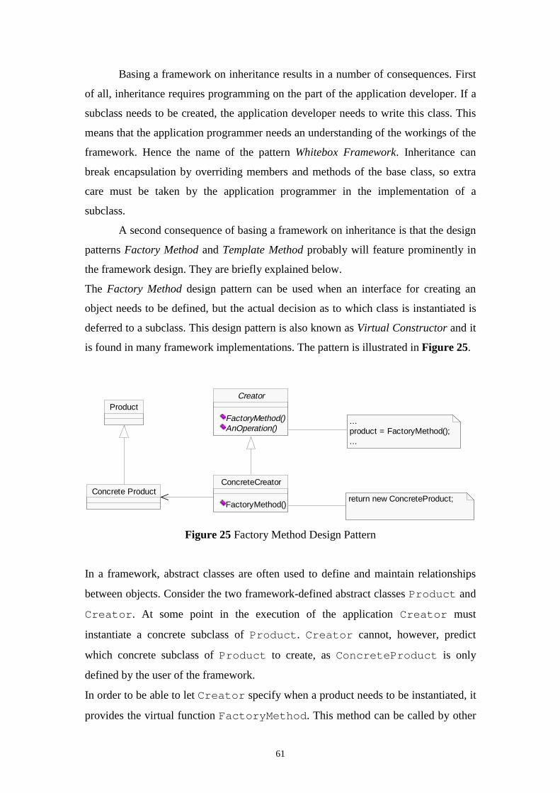
61
Basing a framework on inheritance results in a number of consequences. First
of all, inheritance requires programming on the part of the application developer. If a
subclass needs to be created, the application developer needs to write this class. This
means that the application programmer needs an understanding of the workings of the
framework. Hence the name of the pattern Whitebox Framework. Inheritance can
break encapsulation by overriding members and methods of the base class, so extra
care must be taken by the application programmer in the implementation of a
subclass.
A second consequence of basing a framework on inheritance is that the design
patterns Factory Method and Template Method probably will feature prominently in
the framework design. They are briefly explained below.
The Factory Method design pattern can be used when an interface for creating an
object needs to be defined, but the actual decision as to which class is instantiated is
deferred to a subclass. This design pattern is also known as Virtual Constructor and it
is found in many framework implementations. The pattern is illustrated in Figure 25.
Figure 25 Factory Method Design Pattern
In a framework, abstract classes are often used to define and maintain relationships
between objects. Consider the two framework-defined abstract classes Product and
Creator. At some point in the execution of the application Creator must
instantiate a concrete subclass of Product. Creator cannot, however, predict
which concrete subclass of Product to create, as ConcreteProduct is only
defined by the user of the framework.
In order to be able to let Creator specify when a product needs to be instantiated, it
provides the virtual function FactoryMethod. This method can be called by other
ProductCreator
FactoryMethod()AnOperation()
...product = FactoryMethod();...
return new ConcreteProduct;
ConcreteCreator
FactoryMethod()
Concrete Product
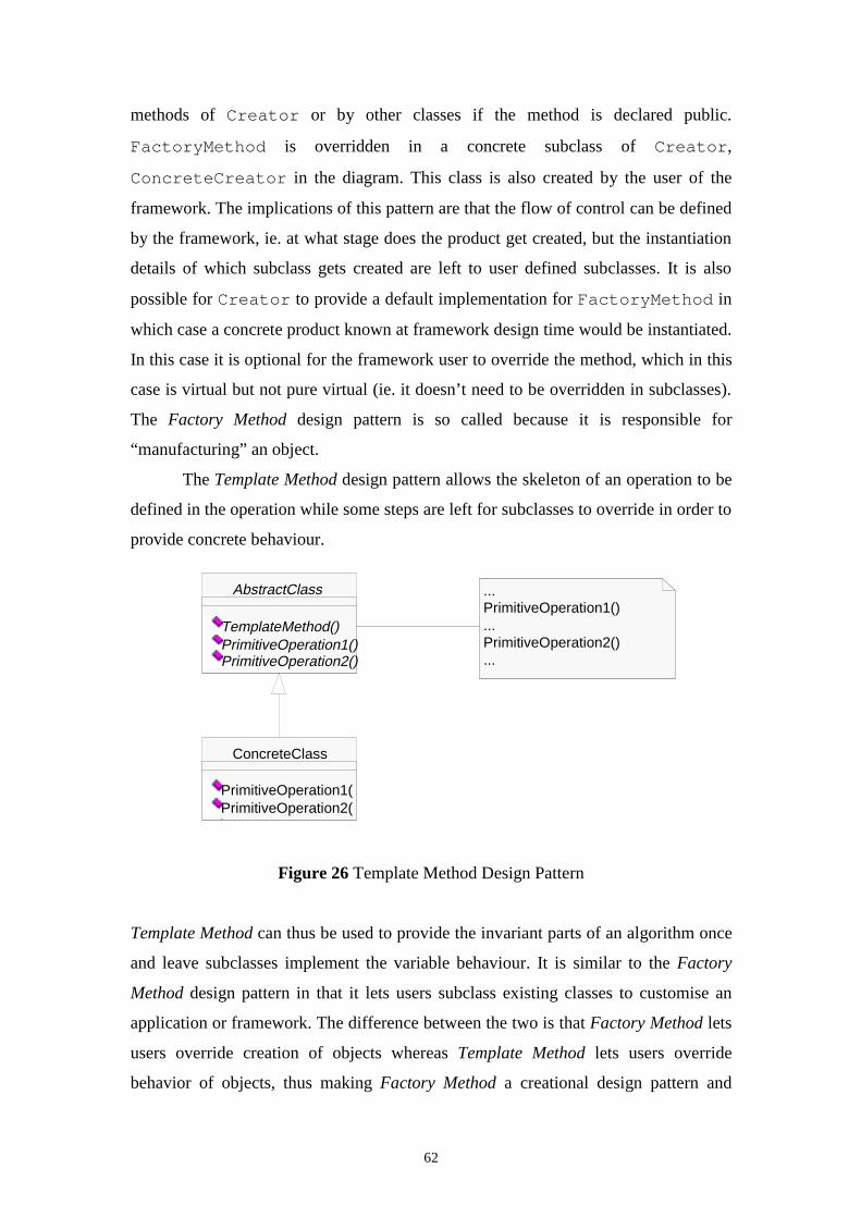
62
methods of Creator or by other classes if the method is declared public.
FactoryMethod is overridden in a concrete subclass of Creator,
ConcreteCreator in the diagram. This class is also created by the user of the
framework. The implications of this pattern are that the flow of control can be defined
by the framework, ie. at what stage does the product get created, but the instantiation
details of which subclass gets created are left to user defined subclasses. It is also
possible for Creator to provide a default implementation for FactoryMethod in
which case a concrete product known at framework design time would be instantiated.
In this case it is optional for the framework user to override the method, which in this
case is virtual but not pure virtual (ie. it doesn’t need to be overridden in subclasses).
The Factory Method design pattern is so called because it is responsible for
“manufacturing” an object.
The Template Method design pattern allows the skeleton of an operation to be
defined in the operation while some steps are left for subclasses to override in order to
provide concrete behaviour.
Figure 26 Template Method Design Pattern
Template Method can thus be used to provide the invariant parts of an algorithm once
and leave subclasses implement the variable behaviour. It is similar to the Factory
Method design pattern in that it lets users subclass existing classes to customise an
application or framework. The difference between the two is that Factory Method lets
users override creation of objects whereas Template Method lets users override
behavior of objects, thus making Factory Method a creational design pattern and
AbstractClass
TemplateMethod()PrimitiveOperation1()PrimitiveOperation2()
ConcreteClass
PrimitiveOperation1()PrimitiveOperation2()
...PrimitiveOperation1()...PrimitiveOperation2()...
63
Template Method a behavioral design pattern. Of course, behavior of objects often
involves the creation of other objects , thus Template Method often uses the Factory
Method design pattern. The structure of Template Method is shown in Figure 26.
TemplateMethod implements a particular algorithm, leaving certain behavior to be
defined in PrimitiveOperation1 and PrimitiveOperation2. These
functions are overridden in ConcreteSubclass which is implemented by the user
that customises the application or framework.
4.2.2 CORBA specified components
The ORB framework is to be used for the building of customised CORBA ORBs.
This means that while ORBs with emphasis on different application scenarios might
be instantiated using the framework, they all must adhere to the OMG CORBA
specification, currently at version 2.2.
The CORBA specification has already been introduced in section 2.4. It is
important to note that the CORBA specification centres around the specification of
interfaces, not implementations. Thus, interfaces for all components of an ORB, such
as the ORB core , the Dynamic Invocation Interface (DII), the Dynamic Skeleton
Interface (DSI), and the Portable Object Adapter (POA), are provided. The
implementation of these principal components, however, is left to the ORB
implementor. No attempt is made in the CORBA specification in prescribing how
these components should be implemented.
Instances of ORBs created using the proposed framework should provide
implementations for these CORBA specific interfaces. In the framework model,
which is presented in this thesis, the principal CORBA specified interfaces should be
included. It is, however, beyond the scope of the model to include all CORBA
specified interfaces. The principal interfaces of the CORBA specification are the
ORB, Object, and POA interfaces. These should be included in the ORB framework
model.
The CORBA specification specifies a number of components which will not
be part of the ORB framework model. These are: an IDL compiler for the generation
of stub and skeleton code from OMG IDL code, an interface repository, and an
implementation repository. These could be added to the model at a later stage.
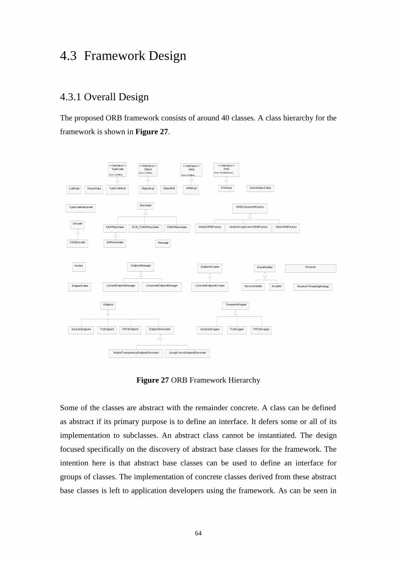
64
4.3 Framework Design
4.3.1 Overall Design
The proposed ORB framework consists of around 40 classes. A class hierarchy for the
framework is shown in Figure 27.
Figure 27 ORB Framework Hierarchy
Some of the classes are abstract with the remainder concrete. A class can be defined
as abstract if its primary purpose is to define an interface. It defers some or all of its
implementation to subclasses. An abstract class cannot be instantiated. The design
focused specifically on the discovery of abstract base classes for the framework. The
intention here is that abstract base classes can be used to define an interface for
groups of classes. The implementation of concrete classes derived from these abstract
base classes is left to application developers using the framework. As can be seen in
IIOPMarshaler
GIOPMarshaler DCE_CSIOPMarshaler ESIOPMarshalerEncoder
CDREncoder
TypeCodeInterpreter
MobileTransparencyEndpointDecorator GroupCommEndpointDecorator
SocketsEndpoint TLIEndpoint FIFOEndpoint EndpointDecorator
TransportWrapper
SocketsWrapper TLIWrapper FIFOWrapper
CallData ParamData TypeCodeImpl
TypeCode
(from CORBA)
<<Interface>>Object
(from CORBA)
<<Interface>>
ObjectRef
ORB
(from CORBA)
<<Interface>>
UncachedEndpointManagerCachedEndpointManagerEndpointTable
EndpointManager EndpointCreator
ConcreteEndpointCreator
Marshaler
Invoker
Endpoint
Message
ORBImpl
ORBComponentFactory
MobileORBFactory MobileGroupCommORBFactory OtherORBFactory
EventHandler
ServiceHandler Acceptor
POA(from PortableServer)
<<Interface>>
Receiver
ReceiverThreadingStrategy
ObjectImpl POAImpl ActiveObjectTable
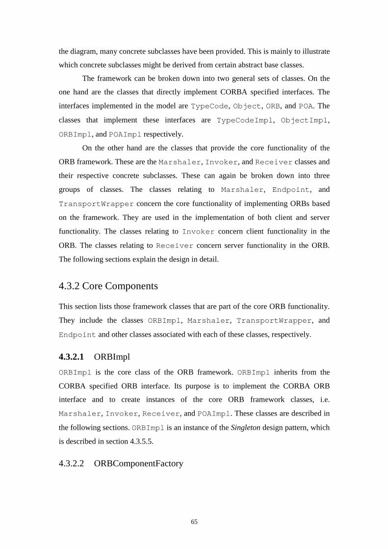
65
the diagram, many concrete subclasses have been provided. This is mainly to illustrate
which concrete subclasses might be derived from certain abstract base classes.
The framework can be broken down into two general sets of classes. On the
one hand are the classes that directly implement CORBA specified interfaces. The
interfaces implemented in the model are TypeCode, Object, ORB, and POA. The
classes that implement these interfaces are TypeCodeImpl, ObjectImpl,
ORBImpl, and POAImpl respectively.
On the other hand are the classes that provide the core functionality of the
ORB framework. These are the Marshaler, Invoker, and Receiver classes and
their respective concrete subclasses. These can again be broken down into three
groups of classes. The classes relating to Marshaler, Endpoint, and
TransportWrapper concern the core functionality of implementing ORBs based
on the framework. They are used in the implementation of both client and server
functionality. The classes relating to Invoker concern client functionality in the
ORB. The classes relating to Receiver concern server functionality in the ORB.
The following sections explain the design in detail.
4.3.2 Core Components
This section lists those framework classes that are part of the core ORB functionality.
They include the classes ORBImpl, Marshaler, TransportWrapper, and
Endpoint and other classes associated with each of these classes, respectively.
4.3.2.1 ORBImpl
ORBImpl is the core class of the ORB framework. ORBImpl inherits from the
CORBA specified ORB interface. Its purpose is to implement the CORBA ORB
interface and to create instances of the core ORB framework classes, i.e.
Marshaler, Invoker, Receiver, and POAImpl. These classes are described in
the following sections. ORBImpl is an instance of the Singleton design pattern, which
is described in section 4.3.5.5.
4.3.2.2 ORBComponentFactory
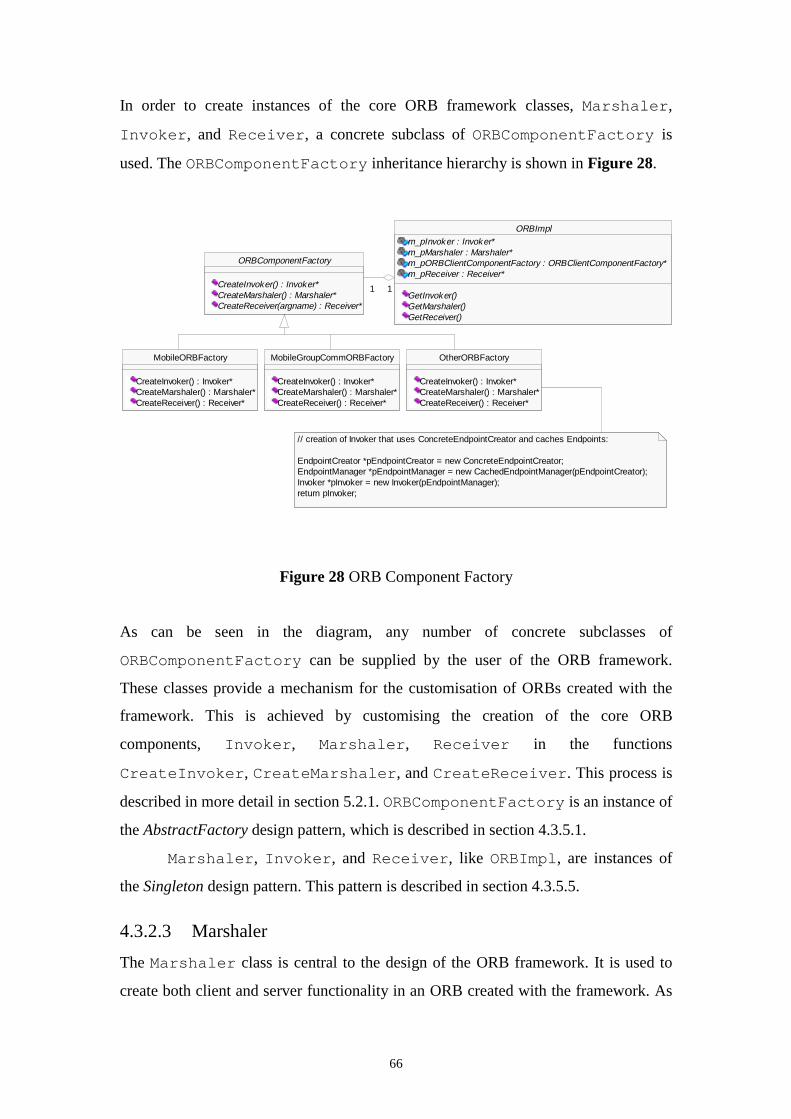
66
In order to create instances of the core ORB framework classes, Marshaler,
Invoker, and Receiver, a concrete subclass of ORBComponentFactory is
used. The ORBComponentFactory inheritance hierarchy is shown in Figure 28.
Figure 28 ORB Component Factory
As can be seen in the diagram, any number of concrete subclasses of
ORBComponentFactory can be supplied by the user of the ORB framework.
These classes provide a mechanism for the customisation of ORBs created with the
framework. This is achieved by customising the creation of the core ORB
components, Invoker, Marshaler, Receiver in the functions
CreateInvoker, CreateMarshaler, and CreateReceiver. This process is
described in more detail in section 5.2.1. ORBComponentFactory is an instance of
the AbstractFactory design pattern, which is described in section 4.3.5.1.
Marshaler, Invoker, and Receiver, like ORBImpl, are instances of
the Singleton design pattern. This pattern is described in section 4.3.5.5.
4.3.2.3 Marshaler
The Marshaler class is central to the design of the ORB framework. It is used to
create both client and server functionality in an ORB created with the framework. As
ORBImplm_pInvoker : Invoker*m_pMarshaler : Marshaler*m_pORBClientComponentFactory : ORBClientComponentFactory*m_pReceiver : Receiver*
GetInvoker()GetMarshaler()GetReceiver()
ORBComponentFactory
CreateInvoker() : Invoker*CreateMarshaler() : Marshaler*CreateReceiver(argname) : Receiver*
11 11
MobileORBFactory
CreateInvoker() : Invoker*CreateMarshaler() : Marshaler*CreateReceiver() : Receiver*
MobileGroupCommORBFactory
CreateInvoker() : Invoker*CreateMarshaler() : Marshaler*CreateReceiver() : Receiver*
OtherORBFactory
CreateInvoker() : Invoker*CreateMarshaler() : Marshaler*CreateReceiver() : Receiver*
// creation of Invoker that uses ConcreteEndpointCreator and caches Endpoints:
EndpointCreator *pEndpointCreator = new ConcreteEndpointCreator;EndpointManager *pEndpointManager = new CachedEndpointManager(pEndpointCreator);Invoker *pInvoker = new Invoker(pEndpointManager);return pInvoker;
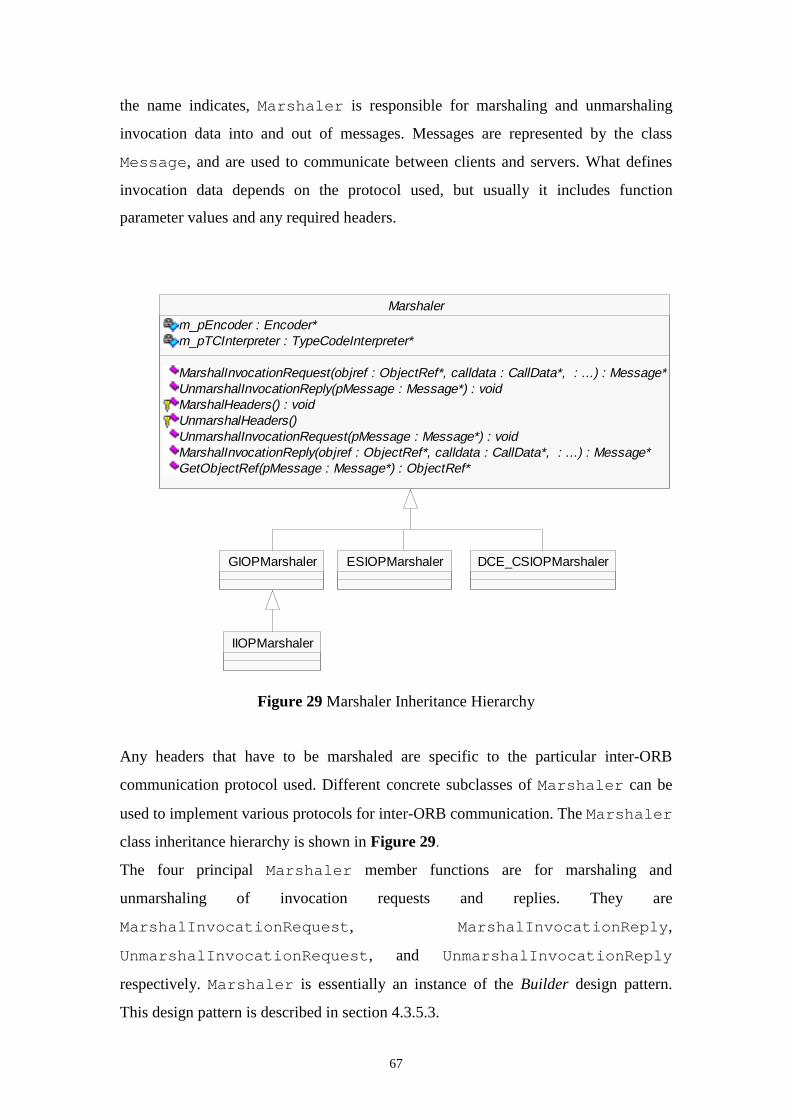
67
the name indicates, Marshaler is responsible for marshaling and unmarshaling
invocation data into and out of messages. Messages are represented by the class
Message, and are used to communicate between clients and servers. What defines
invocation data depends on the protocol used, but usually it includes function
parameter values and any required headers.
Figure 29 Marshaler Inheritance Hierarchy
Any headers that have to be marshaled are specific to the particular inter-ORB
communication protocol used. Different concrete subclasses of Marshaler can be
used to implement various protocols for inter-ORB communication. The Marshaler
class inheritance hierarchy is shown in Figure 29.
The four principal Marshaler member functions are for marshaling and
unmarshaling of invocation requests and replies. They are
MarshalInvocationRequest, MarshalInvocationReply,
UnmarshalInvocationRequest, and UnmarshalInvocationReply
respectively. Marshaler is essentially an instance of the Builder design pattern.
This design pattern is described in section 4.3.5.3.
Marshalerm_pEncoder : Encoder*m_pTCInterpreter : TypeCodeInterpreter*
MarshalInvocationRequest(objref : ObjectRef*, calldata : CallData*, : ...) : Message*UnmarshalInvocationReply(pMessage : Message*) : voidMarshalHeaders() : voidUnmarshalHeaders()UnmarshalInvocationRequest(pMessage : Message*) : voidMarshalInvocationReply(objref : ObjectRef*, calldata : CallData*, : ...) : Message*GetObjectRef(pMessage : Message*) : ObjectRef*
GIOPMarshaler
IIOPMarshaler
ESIOPMarshaler DCE_CSIOPMarshaler
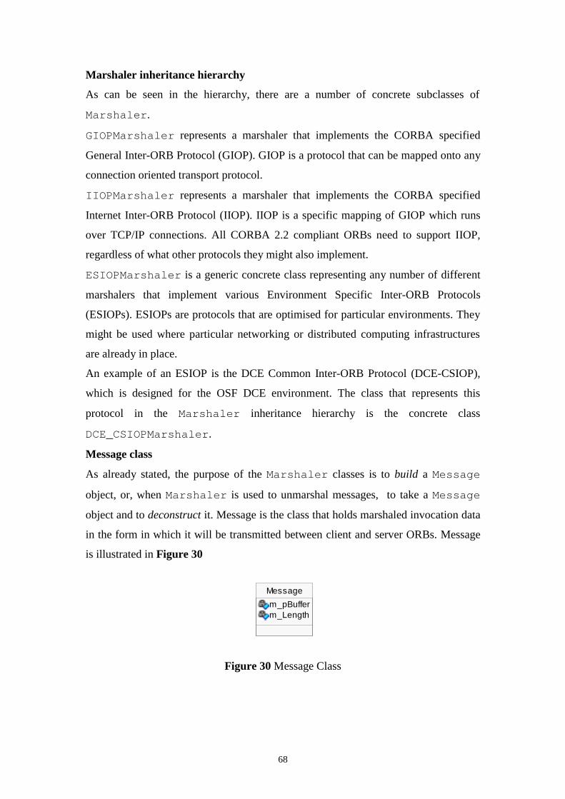
68
Marshaler inheritance hierarchy
As can be seen in the hierarchy, there are a number of concrete subclasses of
Marshaler.
GIOPMarshaler represents a marshaler that implements the CORBA specified
General Inter-ORB Protocol (GIOP). GIOP is a protocol that can be mapped onto any
connection oriented transport protocol.
IIOPMarshaler represents a marshaler that implements the CORBA specified
Internet Inter-ORB Protocol (IIOP). IIOP is a specific mapping of GIOP which runs
over TCP/IP connections. All CORBA 2.2 compliant ORBs need to support IIOP,
regardless of what other protocols they might also implement.
ESIOPMarshaler is a generic concrete class representing any number of different
marshalers that implement various Environment Specific Inter-ORB Protocols
(ESIOPs). ESIOPs are protocols that are optimised for particular environments. They
might be used where particular networking or distributed computing infrastructures
are already in place.
An example of an ESIOP is the DCE Common Inter-ORB Protocol (DCE-CSIOP),
which is designed for the OSF DCE environment. The class that represents this
protocol in the Marshaler inheritance hierarchy is the concrete class
DCE_CSIOPMarshaler.
Message class
As already stated, the purpose of the Marshaler classes is to build a Message
object, or, when Marshaler is used to unmarshal messages, to take a Message
object and to deconstruct it. Message is the class that holds marshaled invocation data
in the form in which it will be transmitted between client and server ORBs. Message
is illustrated in Figure 30
Figure 30 Message Class
Message
m_pBufferm_Length

69
Essentially, Message only contains an unformatted buffer, m_pBuffer of length
m_Length. It contains the invocation data as it is intended to be received by the
receiving ORB.
CallData
In order to understand how invocation data is passed to the Marshaler class and
subsequently marshaled into a Message object, it is necessary to look at how method
invocation data is passed to Marshaler. All information about a method and its
parameters is stored in the CallData class. The composition of this class is
illustrated in Figure 31.
Figure 31 CallData Class Composition
An instance of CallData for each method that has been declared in a CORBA
application’s IDL code needs to be declared in that interface’s client stub and server
skeleton code. This could be achieved through the use of an IDL compiler, or by
manually inserting the required code. CallData contains the method name
(m_MethodName), the number of method parameters (m_NoOfParameters), and
an array of ParamData instances (m_Parameters). There is an instance of
ParamData for each parameter in the method. ParamData contains two members,
a pointer to the TypeCode of the parameter (m_TypeCode) and the parameter
mode (m_ParamMode). The mode of the parameter can take the values MODE_IN,
MODE_OUT, MODE_INOUT, or MODE_RETURN.
A TypeCode is a value that represents invocation argument types. In the framework,
TypeCodes are implemented by the TypeCodeImpl class, which inherits from the
CORBA specified TypeCode interface. TypeCodes can be used in the Dynamic
CallData
m_Parameters : ParamData*m_MethodName : char*m_NoOfParameters : int
ParamData
m_TypeCode : TypeCode_ptrm_ParamMode : ParamMode
1 0..*1 0..*
TypeCodeImpl
m_Kind : TCKind1 11 1
TypeCode
kind() : TCKindmember_count() : ULongmember_type(index : ULong) : TypeCode_ptr
(from CORBA)
<<Interface>>
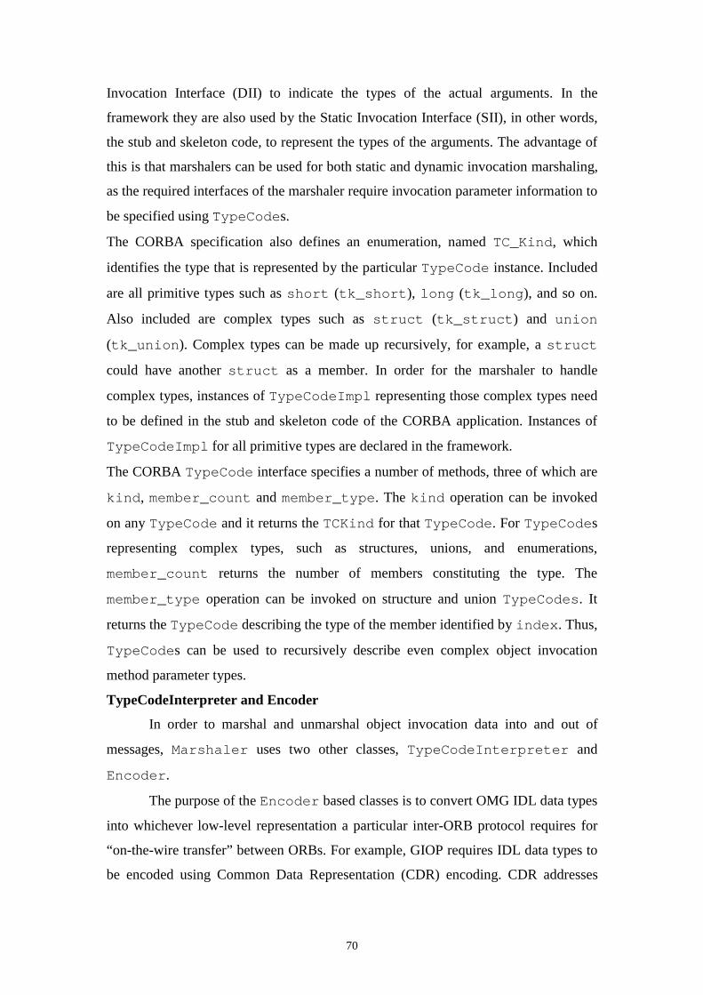
70
Invocation Interface (DII) to indicate the types of the actual arguments. In the
framework they are also used by the Static Invocation Interface (SII), in other words,
the stub and skeleton code, to represent the types of the arguments. The advantage of
this is that marshalers can be used for both static and dynamic invocation marshaling,
as the required interfaces of the marshaler require invocation parameter information to
be specified using TypeCodes.
The CORBA specification also defines an enumeration, named TC_Kind, which
identifies the type that is represented by the particular TypeCode instance. Included
are all primitive types such as short (tk_short), long (tk_long), and so on.
Also included are complex types such as struct (tk_struct) and union
(tk_union). Complex types can be made up recursively, for example, a struct
could have another struct as a member. In order for the marshaler to handle
complex types, instances of TypeCodeImpl representing those complex types need
to be defined in the stub and skeleton code of the CORBA application. Instances of
TypeCodeImpl for all primitive types are declared in the framework.
The CORBA TypeCode interface specifies a number of methods, three of which are
kind, member_count and member_type. The kind operation can be invoked
on any TypeCode and it returns the TCKind for that TypeCode. For TypeCodes
representing complex types, such as structures, unions, and enumerations,
member_count returns the number of members constituting the type. The
member_type operation can be invoked on structure and union TypeCodes. It
returns the TypeCode describing the type of the member identified by index. Thus,
TypeCodes can be used to recursively describe even complex object invocation
method parameter types.
TypeCodeInterpreter and Encoder
In order to marshal and unmarshal object invocation data into and out of
messages, Marshaler uses two other classes, TypeCodeInterpreter and
Encoder.
The purpose of the Encoder based classes is to convert OMG IDL data types
into whichever low-level representation a particular inter-ORB protocol requires for
“on-the-wire transfer” between ORBs. For example, GIOP requires IDL data types to
be encoded using Common Data Representation (CDR) encoding. CDR addresses
71
such issues as byte-ordering, aligning of primitive data types, and mapping of OMG
data types. The Encoder class hierarchy is shown in Figure 32.
Figure 32 Encoder Inheritance Hierarchy
An abstract base class, Encoder, is defined, from which CDREncoder inherits.
CDREncoder implements the CDR encoding scheme used by GIOP. Other encoding
schemes could be represented by new classes derived from Encoder.
TypeCodeInterpreter is used to recursively break down each parameter
into its constituent primitive types if its type is complex. Primitive types are then
encoded or decoded, depending on whether the marshaler is performing marshaling or
unmarshaling. TypeCodeInterpreter is a concrete class since it is used only for
interpreting TypeCodes. In this framework design, the use of TypeCodes is
common to all marshaling and unmarshaling, no matter which inter-ORB protocol,
and hence, which concrete marshaler class is used.
Marshaling and unmarshaling of invocation data
The interaction of Marshaler, TypeCodeInterpreter, and Encoder is
illustrated in Figure 33. If, for example, a client wants to marshal object invocation
data, its stub code calls the Marshaler member function
MarshalInvocationRequest. Its parameters are a pointer to the server object’s
object reference (objref), a pointer to the CallData object (calldata), and
finally, the actual method parameters. For each parameter to be marshaled, the
TypeCodeInterpreter’s Traverse function is called. This function takes as
its arguments
• pTypeCode, the TypeCode_ptr, taken from ParamData
Encoder
Encode(pTypeCode : TypeCode_ptr, stream : void*&, data : void*&) : voidDecode(pTypeCode : TypeCode_ptr, stream : void*&, data : void*&) : void
CDREncoder
Encode(pTypeCode : TypeCode_ptr, stream : void*&, data : void*&) : voidDecode(pTypeCode : TypeCode_ptr, stream : void*&, data : void*&) : void
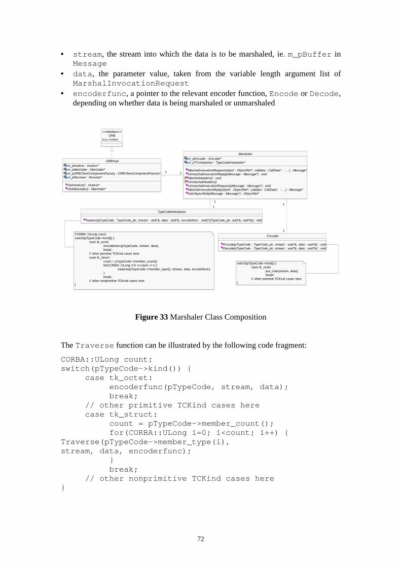
72
• stream, the stream into which the data is to be marshaled, ie. m_pBuffer inMessage
• data, the parameter value, taken from the variable length argument list ofMarshalInvocationRequest
• encoderfunc, a pointer to the relevant encoder function, Encode or Decode,depending on whether data is being marshaled or unmarshaled
Figure 33 Marshaler Class Composition
The Traverse function can be illustrated by the following code fragment:
CORBA::ULong count;switch(pTypeCode->kind()) {
case tk_octet:encoderfunc(pTypeCode, stream, data);break;
// other primitive TCKind cases herecase tk_struct:
count = pTypeCode->member_count();for(CORBA::ULong i=0; i<count; i++) {
Traverse(pTypeCode->member_type(i),stream, data, encoderfunc);
}break;
// other nonprimitive TCKind cases here}
ORB(from CORBA)
<<Interface>>
ORBImplm_pInvoker : Invoker*m_pMarshaler : Marshaler*m_pORBClientComponentFactory : ORBClientComponentFactory*m_pReceiver : Receiver*
GetInvoker() : Invoker*GetMarshaler() : Marshaler*
TypeCodeInterpreter
Traverse(pTypeCode : TypeCode_ptr, stream : void*&, data : void*&, encoderfunc : void(*)(TypeCode_ptr, void*&, void*&)) : void
Marshalerm_pEncoder : Encoder*m_pTCInterpreter : TypeCodeInterpreter*
MarshalInvocationRequest(objref : ObjectRef*, calldata : CallData*, : ...) : Message*UnmarshalInvocationReply(pMessage : Message*) : voidMarshalHeaders() : voidUnmarshalHeaders()UnmarshalInvocationRequest(pMessage : Message*) : voidMarshalInvocationReply(objref : ObjectRef*, calldata : CallData*, : ...) : Message*GetObjectRef(pMessage : Message*) : ObjectRef*
1 11 1
1
1
1
1
Encoder
Encode(pTypeCode : TypeCode_ptr, stream : void*&, data : void*&) : voidDecode(pTypeCode : TypeCode_ptr, stream : void*&, data : void*&) : void
1
1
1
1CORBA::ULong count;switch(pTypeCode->kind()) {
case tk_octet:encoderfunc(pTypeCode, stream, data);break;
// other primitive TCKind cases herecase tk_struct:
count = pTypeCode->member_count();for(CORBA::ULong i=0; i<count; i++) {
traverse(pTypeCode->member_type(i), stream, data, encoderfunc);}break;
// other nonprimitive TCKind cases here}
switch(pTypeCode->kind()) {case tk_octet:
put_char(stream, data);break;
// other primitive TCKind cases here}
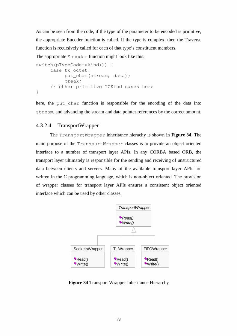
73
As can be seen from the code, if the type of the parameter to be encoded is primitive,
the appropriate Encoder function is called. If the type is complex, then the Traverse
function is recursively called for each of that type’s constituent members.
The appropriate Encoder function might look like this:
switch(pTypeCode->kind()) {case tk_octet:
put_char(stream, data);break;
// other primitive TCKind cases here}
here, the put_char function is responsible for the encoding of the data into
stream, and advancing the stream and data pointer references by the correct amount.
4.3.2.4 TransportWrapper
The TransportWrapper inheritance hierachy is shown in Figure 34. The
main purpose of the TransportWrapper classes is to provide an object oriented
interface to a number of transport layer APIs. In any CORBA based ORB, the
transport layer ultimately is responsible for the sending and receiving of unstructured
data between clients and servers. Many of the available transport layer APIs are
written in the C programming language, which is non-object oriented. The provision
of wrapper classes for transport layer APIs ensures a consistent object oriented
interface which can be used by other classes.
Figure 34 Transport Wrapper Inheritance Hierarchy
TransportWrapper
Read()Write()
SocketsWrapper
Read()Write()
TLIWrapper
Read()Write()
FIFOWrapper
Read()Write()
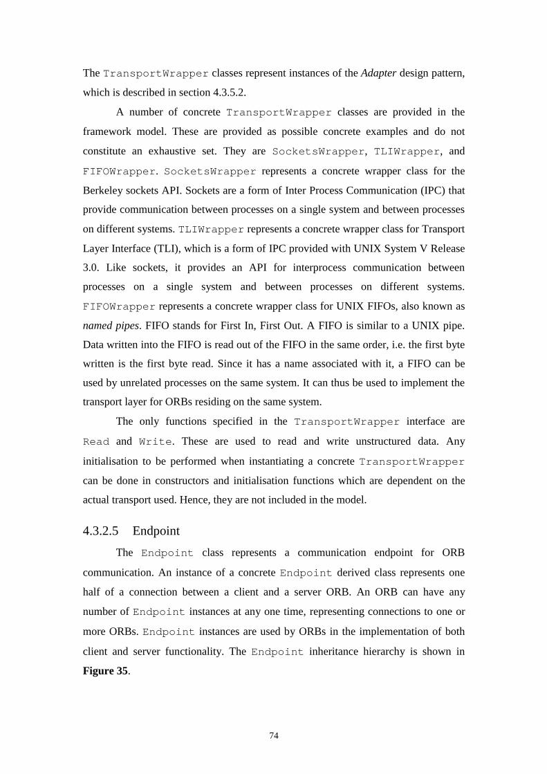
74
The TransportWrapper classes represent instances of the Adapter design pattern,
which is described in section 4.3.5.2.
A number of concrete TransportWrapper classes are provided in the
framework model. These are provided as possible concrete examples and do not
constitute an exhaustive set. They are SocketsWrapper, TLIWrapper, and
FIFOWrapper. SocketsWrapper represents a concrete wrapper class for the
Berkeley sockets API. Sockets are a form of Inter Process Communication (IPC) that
provide communication between processes on a single system and between processes
on different systems. TLIWrapper represents a concrete wrapper class for Transport
Layer Interface (TLI), which is a form of IPC provided with UNIX System V Release
3.0. Like sockets, it provides an API for interprocess communication between
processes on a single system and between processes on different systems.
FIFOWrapper represents a concrete wrapper class for UNIX FIFOs, also known as
named pipes. FIFO stands for First In, First Out. A FIFO is similar to a UNIX pipe.
Data written into the FIFO is read out of the FIFO in the same order, i.e. the first byte
written is the first byte read. Since it has a name associated with it, a FIFO can be
used by unrelated processes on the same system. It can thus be used to implement the
transport layer for ORBs residing on the same system.
The only functions specified in the TransportWrapper interface are
Read and Write. These are used to read and write unstructured data. Any
initialisation to be performed when instantiating a concrete TransportWrapper
can be done in constructors and initialisation functions which are dependent on the
actual transport used. Hence, they are not included in the model.
4.3.2.5 Endpoint
The Endpoint class represents a communication endpoint for ORB
communication. An instance of a concrete Endpoint derived class represents one
half of a connection between a client and a server ORB. An ORB can have any
number of Endpoint instances at any one time, representing connections to one or
more ORBs. Endpoint instances are used by ORBs in the implementation of both
client and server functionality. The Endpoint inheritance hierarchy is shown in
Figure 35.
75
Figure 35 Endpoint Inheritance Hierarchy
As can be seen in the diagram, there are a number of concrete subclasses of
Endpoint. They are SocketsEndpoint, TLIEndpoint, and
FIFOEndpoint. Since a concrete endpoint uses an instance of one of the concrete
TransportWrapper classes to implement communication between the ORBs, a
concrete endpoint is provided for each concrete TransportWrapper class.
Endpoints have one basic purpose. They are used to send and receive
messages between client and server ORBs. For this pupose, Endpoint provides two
basic functions, Send and Receive. Send comes in two forms, one for
synchronous and one for asynchronous transmission. It takes as its argument a
Message pointer. The synchronous version returns a reply Message pointer, while
the asynchronous version doesn’t. Receive returns a Message pointer.
The instantiation of concrete endpoints requires information about the peer
ORB process to which the endpoint represents a connection. If, for example, an ORB
wants to act as client to an ORB acting as server, and a SocketsEndpoint is to be
the type of endpoint used, then, to create the endpoint, the Internet Protocol (IP)
address of the server ORB’s host and the port number on which the server ORB is
SocketsEndpoint
Send(pMessage : Message*) : Message*
SocketsWrapper
Read()Write()
TLIEndpoint
Send(pMessage : Message*) : Message*
TLIWrapper
Read()Write()
FIFOEndpoint
Send(pMessage : Message*) : Message*
FIFOWrapper
Read()Write()
MobileTransparencyEndpointDecorator
Send(pMessage : Message*) : Message*
EndpointDecoratorm_pEndpoint : Endpoint*m_NoOfEndpoints : short
Send(pMessage : Message*) : Message*
Endpointm_TransportWrapper
Send(pMessage : Message*) : Message*Send(pMessage : Message*) : voidReceive() : Message*Accept(argname) : Endpoint*
1
1..*
1
1..*
GroupCommEndpointDecorator
Send(pMessage : Message*) : Message*
76
listening are required. This information may be contained in the object reference for
the server object, and will be provided by the instantiator of the endpoint. Because the
different types of concrete endpoint require different information for connection
initialisation, this is not provided at this point in the framework model.
As can be seen in Figure 35, in addition to the concrete endpoint classes, an
abstract class, EndpointDecorator is derived from Endpoint. It, in turn, has
two concrete subclasses, MobileTransparencyEndpointDecorator and
GroupCommEndpointDecorator. EndpointDecorator is an instance of the
Decorator design pattern. This design pattern is described in section 4.3.5.4. The
purpose of concrete subclasses of EndpointDecorator is to provide additional
functionality for an endpoint if required. An endpoint can be wrapped with an
endpoint decorator class while retaining the Endpoint interface, thus appearing the
same to other classes. An EndpointDecorator itself contains a concrete
Endpoint, so, in a way, the EndpointDecorator class can be seen to be
dynamically adding an extra layer of functionality to the framework.
The purpose of MobileTransparencyEndpointDecorator is to
provide endpoints with additional functionality for mobile applications. Such
functionality could, for example, provide automatic reconnection and retransmission
of lost messages in case of a mobile connection breaking down.
The purpose of GroupCommEndpointDecorator is to provide endpoints
with additional functionality for object group communication. It could be
implemented to provide reliable multicast to groups of objects represented by one
endpoint to other objects. In other words, a GroupCommEndpointDecorator
appears as a single endpoint to other objects in the ORB, but it itself could contain a
number of concrete endpoints representing the objects in that group.
EndpointCreator
The EndpointCreator inheritance hierarchy is shown in Figure 36. In this
hierarchy, one generic concrete class, ConcreteEndpointCreator, represents
any number of classes inherited from EndpointCreator that might be provided
by the user of the ORB framework. EndpointCreator provides an interface for
the creation of concrete Endpoint objects. A concrete EndpointCreator class
is one of the classes that must be provided by the user of the ORB framework,
although default implementations could also be be provided. Concrete subclasses of
77
EndpointCreator instantiate Endpoint objects in the function
CreateEndpoint. An example implementation of this function in a concrete
EndpointCreator class might look as follows:
Endpoint* CreateEndpoint(ObjectRef* pObjectRef){
Endpoint* pEndpoint = new SocketsEndpoint;// set Endpoint parameters from pObjectRef here.// This depends on format of object reference and// concrete transport endpoint usedEndpoint* pWrapperEndpoint = new
MobileTransparencyEndpoint(pEndpoint);return pWrapperEndpoint;
}
This function creates an endpoint that uses the sockets transport wrapper class and has
mobile transparency.
To create an Endpoint in CreateEndpoint, an object reference is required. This
is represented by the class ObjectRef, and its concrete form depends on the inter-ORB
protocol used. For example, if the inter-ORB protocol used is IIOP, then the object
reference will contain the object host’s IP address and the port number on which the
server ORB is listening. In this case, in the function CreateEndpoint this information
is used to initialise a sockets endpoint.
EndpointCreator is an instance of the Strategy design pattern, which is
described in section 4.3.5.6.
4.3.3 Components for client functionality
This section lists those framework classes that are used to create client functionality in
the ORB. They include the classes Invoker and EndpointManager, and other
classes associated with each of these classes, respectively.
4.3.3.1 Invoker
The class diagram illustrating the composition of Invoker is illustrated in Figure
36. Invoker, as its name suggests, is responsible for performing invocations of
remote objects. Basically, this consists of Invoker sending and receiving messages
that contain marshaled invocation data. Invoker is not responsible for marshaling or
unmarshaling of invocation data. It is purely concerned with managing any number of
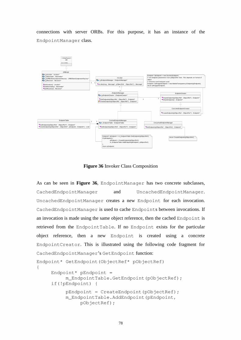
78
connections with server ORBs. For this purpose, it has an instance of the
EndpointManager class.
Figure 36 Invoker Class Composition
As can be seen in Figure 36, EndpointManager has two concrete subclasses,
CachedEndpointManager and UncachedEndpointManager.
UncachedEndpointManager creates a new Endpoint for each invocation.
CachedEndpointManager is used to cache Endpoints between invocations. If
an invocation is made using the same object reference, then the cached Endpoint is
retrieved from the EndpointTable. If no Endpoint exists for the particular
object reference, then a new Endpoint is created using a concrete
EndpointCreator. This is illustrated using the following code fragment for
CachedEndpointManager’s GetEndpoint function:
Endpoint* GetEndpoint(ObjectRef* pObjectRef){
Endpoint* pEndpoint =m_EndpointTable.GetEndpoint(pObjectRef);
if(!pEndpoint) {
pEndpoint = CreateEndpoint(pObjectRef);m_EndpointTable.AddEndpoint(pEndpoint,
pObjectRef);
OR
(from CORBA)
<<Interf ace>>
UncachedEndpointManager
GetEndpoint(pObjectRef : ObjectRef ) : Endpoint*
CachedEndpointManager
m_EndpointTable : EndpointTable
GetEndpoint(pObjectRef : ObjectRef *) : Endpoint*
EndpointTable
GetEndpoint(pObjectRef : ObjectRef *) : Endpoint*InsertEndpoint(pObjectRef : ObjectRef *, pEndpoint : Endpoint*) : v oid
11 11
ORBImpl
m_pInvoker : Invoker*m_pMarshaler : Marshaler*m_pORBClientComponentFactory : ORBClientComponentFactory*m_pReceiver : Receiver*
GetInvoker() : Invoker*GetMarshaler() : Marshaler*GetReceiver() : Receiver*
Inv oker
m_pEndpointManager : EndpointManager*
Inv oke(msg : Message*, pObjectRef : ObjectRef *) : Message*11 11
EndpointManager
m_pEndpointCreator : EndpointCreator*
GetEndpoint(pObjectRef : ObjectRef*) : Endpoint*CreateEndpoint(pObjectRef : ObjectRef*) : Endpoint*
1
1
1
1
EndpointCreator
CreateEndpoint(pObjectRef : ObjectRef*) : Endpoint*CreateEndpoint() : Endpoint*
11 11
ConcreteEndpointCreator
CreateEndpoint(pObjectRef : ObjectRef *) : Endpoint*
return CreateEndpoint(pObjectRef );Endpoint* pEndpoint = m_EndpointTable.GetEndpoint(pObjectRef );if (!pEndpoint) {
pEndpoint = CreateEndpoint(pObjectRef );m_EndpointTable.AddEndpoint(pEndpoint, pObjectRef );
}return pEndpoint;
Endpoint *pEndpoint = new SocketsEndpoint;// set Endpoint parameters f rom pObjectRef here. This depends on f ormat of object // ref erence and transport usedEndpoint *pWrapperEndpoint = new MobileTransparency Endpoint(pEndpoint);return pWrapperEndpoint;
79
}return pEndpoint;
}
In this example, EndpointTable::GetEndpoint returns a null pointer if no
match for pObjectRef exists in the table, in other words, no cached Endpoint
exists that matches the supplied object reference.
EndpointManager is an instance of the Strategy design pattern, which is described
in section 4.3.5.6.
4.3.4 Components for server functionality
This section lists those framework classes that are used to create server functionality
in the ORB. They include the classes Receiver and POAImpl, and other classes
associated with each of these classes, respectively.
4.3.4.1 Receiver
The purpose of the Receiver class and its associated classes is to provide
the ability to establish connections for providing server functionality in the ORB.
Receiver and its associated classes are shown in Figure 37. The principal purpose
of the Receiver class is to act as demultiplexer of incoming messages for any
instances of EventHandler registered with it. As can be seen in the
EventHandler inheritance hierarchy, EventHandler has two concrete
subclasses, Acceptor and ServiceHandler. Both Acceptor and
ServiceHandler use an instance of Endpoint to implement the server end of a
connection between client and server ORBs. Acceptor is responsible for the
establishment of a connection, while ServiceHandler is responsible for handling
any subsequent requests incoming on that connection. EventHandlers register
with Receiver by calling its RegisterHandler function. Receiver then
demultiplexes any incoming messages for EventHandlers registered with it. It
achieves this by utilising a system call for event demultiplexing, for example select if
using sockets. One Acceptor can create one or more ServiceHandlers as it
accepts new connections. For example, if using sockets, the Acceptor’s
SocketsEndpoint can use the system call accept to create a new endpoint for
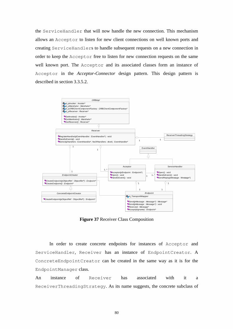
80
the ServiceHandler that will now handle the new connection. This mechanism
allows an Acceptor to listen for new client connections on well known ports and
creating ServiceHandlers to handle subsequent requests on a new connection in
order to keep the Acceptor free to listen for new connection requests on the same
well known port. The Acceptor and its associated classes form an instance of
Acceptor in the Acceptor-Connector design pattern. This design pattern is
described in section 3.3.5.2.
Figure 37 Receiver Class Composition
In order to create concrete endpoints for instances of Acceptor and
ServiceHandler, Receiver has an instance of EndpointCreator. A
ConcreteEndpointCreator can be created in the same way as it is for the
EndpointManager class.
An instance of Receiver has associated with it a
ReceiverThreadingStrategy. As its name suggests, the concrete subclass of
EventHandler
ConcreteEndpointCreator
CreateEndpoint(pObjectRef : ObjectRef*) : Endpoint*
ReceiverThreadingStrategy
ORBImpl
m_pInvoker : Invoker*m_pMarshaler : Marshaler*m_pORBCl ientComponentFactory : ORBCl ientComponentFactory*m_pReceiver : Receiver*
GetInvoker() : Invoker*GetMarshaler() : Marshaler*GetReceiver() : Receiver*
ServiceHandler
Open() : voidHandleEvent() : voidSendReply(pMessage : Message*)
Endpoint
m_TransportWrapper
Send(pMessage : Message*) : Message*Send(pMessage : Message*) : voidReceive() : Message*Accept(argname) : Endpoint*
1
1
1
1
EndpointCreator
CreateEndpoint(pObjectRef : ObjectRef*) : Endpoint*CreateEndpoint() : Endpoint*
Receiver
RegisterHandler(pEventHandler : EventHandler*) : voidHandleEvents() : voidSelect(pHandlers : EventHandler*, NoOfHandlers : short) : EventHandler*
1 11 1
1
1
1
1
Acceptor
Acceptor(pEndpoint : Endpoint*)Open() : voidHandleEvent() : void
1 1..*1 1..*
1
1
1
1
1
1..*
1
1..*
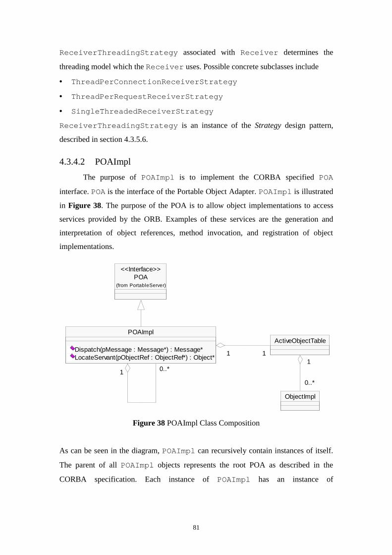
81
ReceiverThreadingStrategy associated with Receiver determines the
threading model which the Receiver uses. Possible concrete subclasses include
• ThreadPerConnectionReceiverStrategy
• ThreadPerRequestReceiverStrategy
• SingleThreadedReceiverStrategy
ReceiverThreadingStrategy is an instance of the Strategy design pattern,
described in section 4.3.5.6.
4.3.4.2 POAImpl
The purpose of POAImpl is to implement the CORBA specified POA
interface. POA is the interface of the Portable Object Adapter. POAImpl is illustrated
in Figure 38. The purpose of the POA is to allow object implementations to access
services provided by the ORB. Examples of these services are the generation and
interpretation of object references, method invocation, and registration of object
implementations.
Figure 38 POAImpl Class Composition
As can be seen in the diagram, POAImpl can recursively contain instances of itself.
The parent of all POAImpl objects represents the root POA as described in the
CORBA specification. Each instance of POAImpl has an instance of
POA(from PortableServer)
<<Interface>>
ObjectImpl
ActiveObjectTable
1
0..*
1
0..*
POAImpl
Dispatch(pMessage : Message*) : Message*LocateServant(pObjectRef : ObjectRef*) : Object*
1 0..*1 0..*
1 111
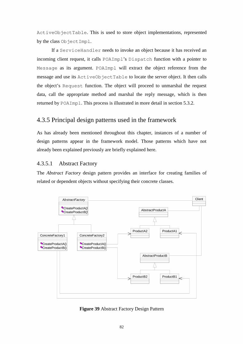
82
ActiveObjectTable. This is used to store object implementations, represented
by the class ObjectImpl.
If a ServiceHandler needs to invoke an object because it has received an
incoming client request, it calls POAImpl’s Dispatch function with a pointer to
Message as its argument. POAImpl will extract the object reference from the
message and use its ActiveObjectTable to locate the server object. It then calls
the object’s Request function. The object will proceed to unmarshal the request
data, call the appropriate method and marshal the reply message, which is then
returned by POAImpl. This process is illustrated in more detail in section 5.3.2.
4.3.5 Principal design patterns used in the framework
As has already been mentioned throughout this chapter, instances of a number of
design patterns appear in the framework model. Those patterns which have not
already been explained previously are briefly explained here.
4.3.5.1 Abstract Factory
The Abstract Factory design pattern provides an interface for creating families of
related or dependent objects without specifying their concrete classes.
Figure 39 Abstract Factory Design Pattern
ConcreteFactory1
CreateProductA()CreateProductB()
ConcreteFactory2
CreateProductA()CreateProductB()
ProductA2 ProductA1
ProductB2 ProductB1
AbstractFactory
CreateProductA()CreateProductB()
AbstractProductA
AbstractProductB
Client
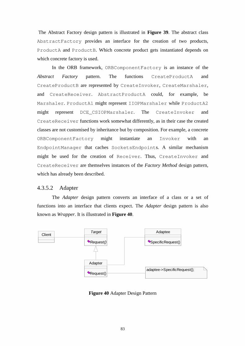
83
The Abstract Factory design pattern is illustrated in Figure 39. The abstract class
AbstractFactory provides an interface for the creation of two products,
ProductA and ProductB. Which concrete product gets instantiated depends on
which concrete factory is used.
In the ORB framework, ORBComponentFactory is an instance of the
Abstract Factory pattern. The functions CreateProductA and
CreateProductB are represented by CreateInvoker, CreateMarshaler,
and CreateReceiver. AbstractProductA could, for example, be
Marshaler. ProductA1 might represent IIOPMarshaler while ProductA2
might represent DCE_CSIOPMarshaler. The CreateInvoker and
CreateReceiver functions work somewhat differently, as in their case the created
classes are not customised by inheritance but by composition. For example, a concrete
ORBComponentFactory might instantiate an Invoker with an
EndpointManager that caches SocketsEndpoints. A similar mechanism
might be used for the creation of Receiver. Thus, CreateInvoker and
CreateReceiver are themselves instances of the Factory Method design pattern,
which has already been described.
4.3.5.2 Adapter
The Adapter design pattern converts an interface of a class or a set of
functions into an interface that clients expect. The Adapter design pattern is also
known as Wrapper. It is illustrated in Figure 40.
Figure 40 Adapter Design Pattern
Target
Request()
ClientAdaptee
SpecificRequest()
Adapter
Request()adaptee->SpecificRequest();
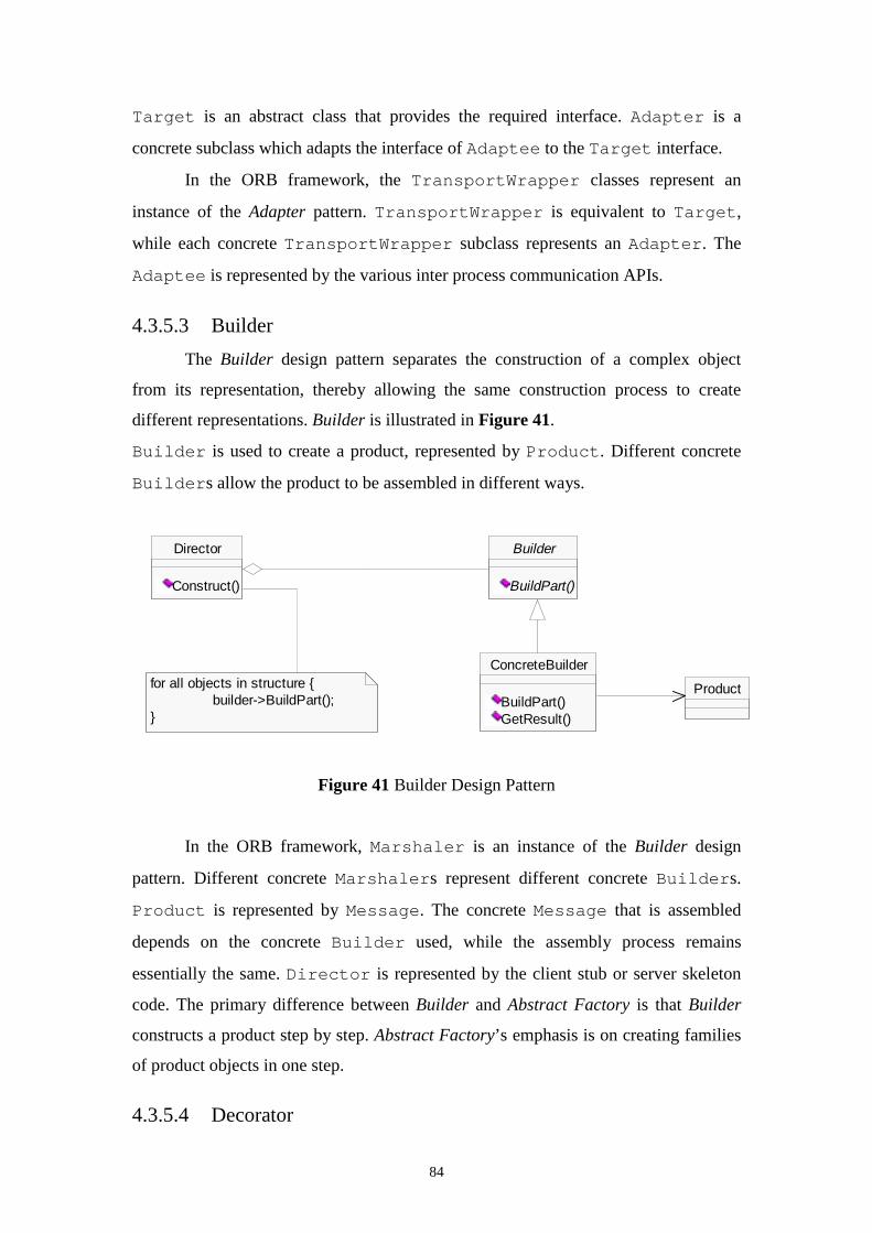
84
Target is an abstract class that provides the required interface. Adapter is a
concrete subclass which adapts the interface of Adaptee to the Target interface.
In the ORB framework, the TransportWrapper classes represent an
instance of the Adapter pattern. TransportWrapper is equivalent to Target,
while each concrete TransportWrapper subclass represents an Adapter. The
Adaptee is represented by the various inter process communication APIs.
4.3.5.3 Builder
The Builder design pattern separates the construction of a complex object
from its representation, thereby allowing the same construction process to create
different representations. Builder is illustrated in Figure 41.
Builder is used to create a product, represented by Product. Different concrete
Builders allow the product to be assembled in different ways.
Figure 41 Builder Design Pattern
In the ORB framework, Marshaler is an instance of the Builder design
pattern. Different concrete Marshalers represent different concrete Builders.
Product is represented by Message. The concrete Message that is assembled
depends on the concrete Builder used, while the assembly process remains
essentially the same. Director is represented by the client stub or server skeleton
code. The primary difference between Builder and Abstract Factory is that Builder
constructs a product step by step. Abstract Factory’s emphasis is on creating families
of product objects in one step.
4.3.5.4 Decorator
ConcreteBuilder
BuildPart()GetResult()
Product
Director
Construct()
Builder
BuildPart()
for all objects in structure {builder->BuildPart();
}
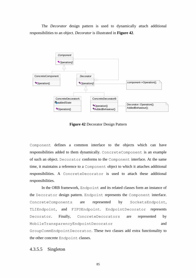
85
The Decorator design pattern is used to dynamically attach additional
responsibilities to an object. Decorator is illustrated in Figure 42.
Figure 42 Decorator Design Pattern
Component defines a common interface to the objects which can have
responsibilities added to them dynamically. ConcreteComponent is an example
of such an object. Decorator conforms to the Component interface. At the same
time, it maintains a reference to a Component object to which it attaches additional
responsibilities. A ConcreteDecorator is used to attach these additional
responsibilities.
In the ORB framework, Endpoint and its related classes form an instance of
the Decorator design pattern. Endpoint represents the Component interface.
ConcreteComponents are represented by SocketsEndpoint,
TLIEndpoint, and FIFOEndpoint. EndpointDecorator represents
Decorator. Finally, ConcreteDecorators are represented by
MobileTransparencyEndpointDecorator and
GroupCommEndpointDecorator. These two classes add extra functionality to
the other concrete Endpoint classes.
4.3.5.5 Singleton
ConcreteComponent
Operation()
ConcreteDecoratorA
addedState
Operation()
ConcreteDecoratorB
Operation()AddedBehaviour()
component->Operation();
Decorator
Operation()
Component
Operation()
Decorator::Operation();AddedBehaviour();
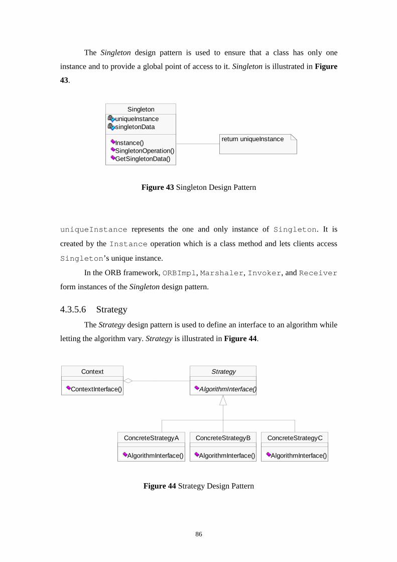
86
The Singleton design pattern is used to ensure that a class has only one
instance and to provide a global point of access to it. Singleton is illustrated in Figure
43.
Figure 43 Singleton Design Pattern
uniqueInstance represents the one and only instance of Singleton. It is
created by the Instance operation which is a class method and lets clients access
Singleton’s unique instance.
In the ORB framework, ORBImpl, Marshaler, Invoker, and Receiver
form instances of the Singleton design pattern.
4.3.5.6 Strategy
The Strategy design pattern is used to define an interface to an algorithm while
letting the algorithm vary. Strategy is illustrated in Figure 44.
Figure 44 Strategy Design Pattern
Singleton
uniqueInstancesingletonData
Instance()SingletonOperation()GetSingletonData()
return uniqueInstance
ConcreteStrategyA
AlgorithmInterface()
ConcreteStrategyB
AlgorithmInterface()
ConcreteStrategyC
AlgorithmInterface()
Context
ContextInterface()
Strategy
AlgorithmInterface()
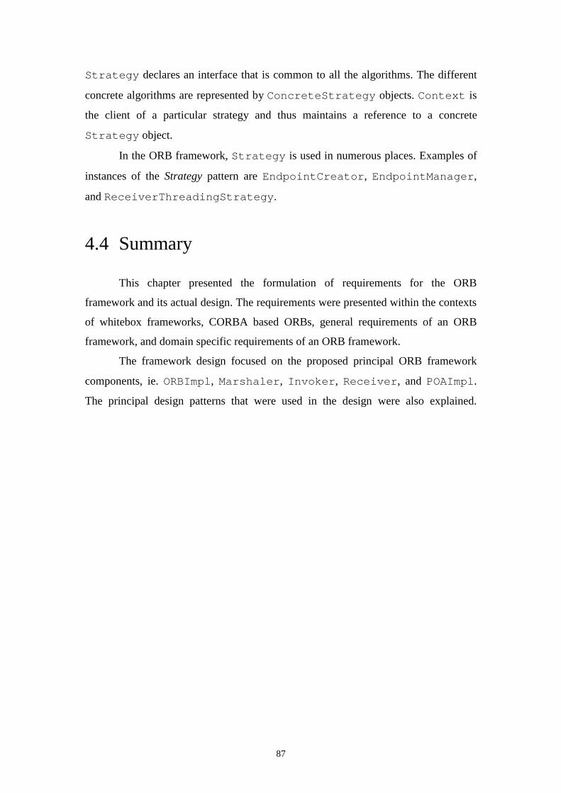
87
Strategy declares an interface that is common to all the algorithms. The different
concrete algorithms are represented by ConcreteStrategy objects. Context is
the client of a particular strategy and thus maintains a reference to a concrete
Strategy object.
In the ORB framework, Strategy is used in numerous places. Examples of
instances of the Strategy pattern are EndpointCreator, EndpointManager,
and ReceiverThreadingStrategy.
4.4 Summary
This chapter presented the formulation of requirements for the ORB
framework and its actual design. The requirements were presented within the contexts
of whitebox frameworks, CORBA based ORBs, general requirements of an ORB
framework, and domain specific requirements of an ORB framework.
The framework design focused on the proposed principal ORB framework
components, ie. ORBImpl, Marshaler, Invoker, Receiver, and POAImpl.
The principal design patterns that were used in the design were also explained.
88
Chapter 5
Evaluation of the Object RequestBroker Framework
5.1 Introduction
The objective of this chapter is to illustrate how the framework can be used to create
customised ORBs. It also demonstrates how an ORB created using the framework
would execute a simple object invocation. This is visualised using Unified Modeling
Language (UML) sequence diagrams.
5.2 Creating customised Object Request Brokers
The ORB framework can be used in a number of ways to provide various degrees of
ORB customisation. Customisation of the principal components of the ORB can be
achieved by implementing a concrete subclass of ORBComponentFactory. A
concrete EndpointCreator must also be provided in order to allow it create the
required concrete Endpoints from the object references used by the ORB. To
provide even more customised behaviour, any of the abstract classes in the framework
can be inherited from to provide behaviour that was unforeseen at framework design
time.
5.2.1 Creating a concrete ORBComponentFactory
89
The most basic way in which to customise an ORB using the framework is to provide
a concrete subclass of ORBComponentFactory. As described in the previous
chapter, this class is responsible for creating the main components of the ORB, i.e.
Marshaler, Invoker, and Receiver. By providing a concrete subclass of
ORBComponentFactory, these principal components can be customised.
ORBComponentFactory’s function CreateMarshaler is used to
instantiate a concrete subclass of Marshaler. If, for example, an
IIOPMarshaler is to be created, CreateMarshaler should be written as
follows:
Marshaller* CreateMarshaler(){
return new IIOPMarshaler;}
Similarly, CreateInvoker is used to create an instance of Invoker. Since
Invoker is a concrete class itself, and does not form part of an inheritance hierarchy,
no subclass of Invoker needs to be created by the application programmer. Rather,
Invoker is customised by configuring it with a concrete EndpointManager, which, in
turn, is customised with a concrete EndpointCreator. This process can be illustrated
by the following sample code for ORBComponentFactory::CreateInvoker():
Invoker* CreateInvoker(){
// creation of Invoker that uses// ConcreteEndpointCreator// and caches EndpointsEndpointCreator* pEndpointCreator =
new ConcreteEndpointCreator;EndpointManager* pEndpointManager =
new CachedEndpointManager(pEndpointCreator);Invoker* pInvoker = new Invoker(pEndpointManager);return pInvoker;
}
Thus, it can be seen that the customisation of Invoker relies somewhat on object
composition as well as inheritance. In a purely black-box framework customisation
would only require object composition since all concrete classes would already be
provided as components in the framework.
Finally, CreateReceiver is used to create instances of Receiver. This
function needs to be implemented in a similar way to CreateInvoker, since it
90
needs to create an EndpointCreator that will be used by Receiver. In the
same function, Receiver needs to be configured with a concrete
ReceiverThreadingStrategy:
Receiver* CreateReceiver(){
EndpointCreator* pEndpointCreator =new ConcreteEndpointCreator;
ReceiverThreadingStrategy* pThreadingStrat =new ThreadPerRequestReceiverThreadingStrategy;
Receiver* pReceiver = new Receiver(ConcreteEndpointCreator,ThreadPerRequestReceiverThreadingStrategy);
return pReceiver;}
5.2.2 Creating a concrete EndpointCreator
The class EndpointCreator is responsible for creating instances of concrete
Endpoints. A concrete EndpointCreator needs to be supplied by the user of
the framework in order to map an object reference to the required
TransportWrapper’s parameters needed to initialise an Endpoint. The
EndpointCreator function in which a concrete Endpoint is created is
CreateEndpoint. Sample code for this function was given in the previous
chapter.
5.2.3 Inheriting from other abstract framework classes
In addition to inheriting from the abstract classes mentioned above, the framework
permits the creation of customised ORBs by inheriting from other abstract classes in
the framework. If, for example, a new inter-ORB protocol is to be created, a new
concrete class could be inherited from Marshaler in order to implement this
protocol. This might also require the creation of a new Encoder class, as the
required low level data encoding method may vary from those used for existing
protocols.
Likewise, other classes could be added to the framework as the need arises. For
example, other concrete TransportWrapper classes could be added, and with
them the associated Endpoint classes.
91
5.3 A sample object invocation
This section illustrates how an ORB created with the framework would
perform a simple object invocation. Sequence diagrams for object interaction are
provided in the Unified Modeling Language (UML). As an example, consider the
following IDL code:
Interface Calculator{
struct Group{
octet o;long l;short s;
};Group CubeStruct(in Group values);
};
This interface defines a method that takes as its argument an instance of a simple
structure. It returns an instance of the same structure. The purpose of the method is to
simply cube each element in the structure and return the structure.
In order to use this interface in order to perform CORBA object invocation a
stub and a skeleton class are required. These are illustrated in Figure 45. As can be
seen in the diagram, ObjectImpl is the framework class that implements the CORBA
Object interface. ObjectImpl contains a reference to an instance of the ObjectRef
class. This class represents an object reference. The contents of ObjectRef depend on
the inter-ORB protocol used in the implementation of the ORB. Inherited from
ObjectImpl is the class Calculator. This class specifies the Calculator interface based
on the IDL definition. Calculator_Stub and Calculator_Skeleton both inherit from
Calculator. They provide the stub and skeleton classes respectively. The classes
Calculator, Calculator_Stub, and Calculator_Skeleton could be created manually or
by a suitable IDL compiler. Finally, Calculator_Impl needs to be provided by the
application programmer. It provides the implementation of the Calculator interface.
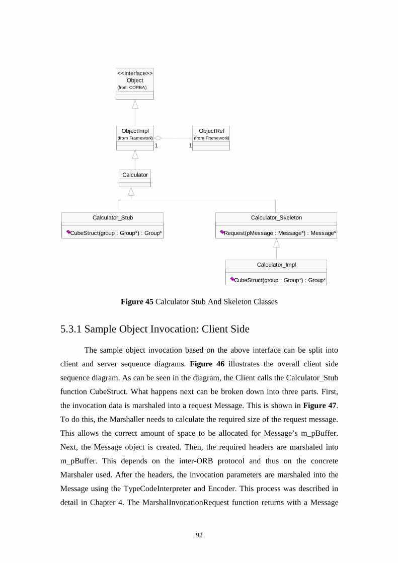
92
Figure 45 Calculator Stub And Skeleton Classes
5.3.1 Sample Object Invocation: Client Side
The sample object invocation based on the above interface can be split into
client and server sequence diagrams. Figure 46 illustrates the overall client side
sequence diagram. As can be seen in the diagram, the Client calls the Calculator_Stub
function CubeStruct. What happens next can be broken down into three parts. First,
the invocation data is marshaled into a request Message. This is shown in Figure 47.
To do this, the Marshaller needs to calculate the required size of the request message.
This allows the correct amount of space to be allocated for Message’s m_pBuffer.
Next, the Message object is created. Then, the required headers are marshaled into
m_pBuffer. This depends on the inter-ORB protocol and thus on the concrete
Marshaler used. After the headers, the invocation parameters are marshaled into the
Message using the TypeCodeInterpreter and Encoder. This process was described in
detail in Chapter 4. The MarshalInvocationRequest function returns with a Message
Calculator
Calculator_Stub
CubeStruct(group : Group*) : Group*
Calculator_Skeleton
Request(pMessage : Message*) : Message*
Calculator_Impl
CubeStruct(group : Group*) : Group*
Object(from CORBA)
<<Interface>>
ObjectRef(from Framework)
ObjectImpl(from Framework)
11 11
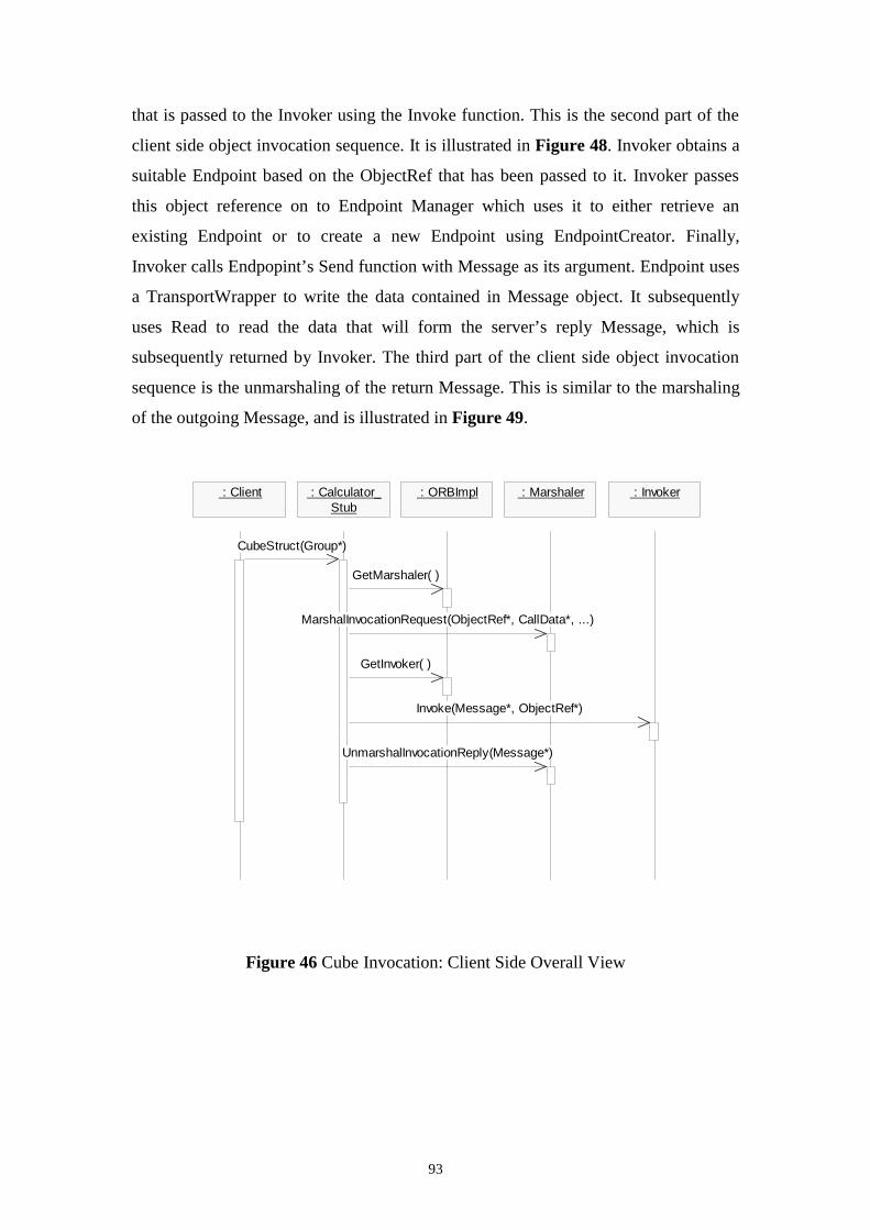
93
that is passed to the Invoker using the Invoke function. This is the second part of the
client side object invocation sequence. It is illustrated in Figure 48. Invoker obtains a
suitable Endpoint based on the ObjectRef that has been passed to it. Invoker passes
this object reference on to Endpoint Manager which uses it to either retrieve an
existing Endpoint or to create a new Endpoint using EndpointCreator. Finally,
Invoker calls Endpopint’s Send function with Message as its argument. Endpoint uses
a TransportWrapper to write the data contained in Message object. It subsequently
uses Read to read the data that will form the server’s reply Message, which is
subsequently returned by Invoker. The third part of the client side object invocation
sequence is the unmarshaling of the return Message. This is similar to the marshaling
of the outgoing Message, and is illustrated in Figure 49.
Figure 46 Cube Invocation: Client Side Overall View
: Client : Calculator_Stub
: ORBImpl : Marshaler : Invoker
CubeStruct(Group*)
GetMarshaler( )
MarshalInvocationRequest(ObjectRef*, CallData*, ...)
GetInvoker( )
Invoke(Message*, ObjectRef*)
UnmarshalInvocationReply(Message*)
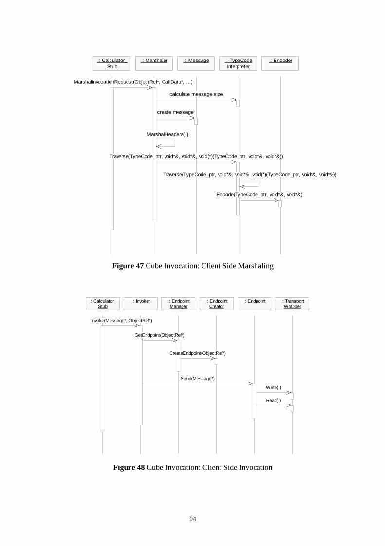
94
Figure 47 Cube Invocation: Client Side Marshaling
Figure 48 Cube Invocation: Client Side Invocation
: Calculator_Stub
: Marshaler : Message : TypeCodeInterpreter
: Encoder
MarshalInvocationRequest(ObjectRef*, CallData*, ...)
calculate message size
create message
MarshalHeaders( )
Traverse(TypeCode_ptr, void*&, void*&, void(*)(TypeCode_ptr, void*&, void*&))
Traverse(TypeCode_ptr, void*&, void*&, void(*)(TypeCode_ptr, void*&, void*&))
Encode(TypeCode_ptr, void*&, void*&)
: Calculator_Stub
: Invoker : EndpointManager
: EndpointCreator
: Endpoint : TransportWrapper
Invoke(Message*, ObjectRef*)
GetEndpoint(ObjectRef*)
CreateEndpoint(ObjectRef*)
Send(Message*)
Write( )
Read( )
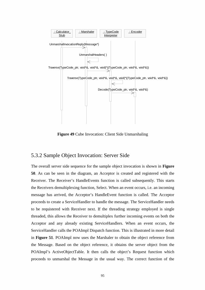
95
Figure 49 Cube Invocation: Client Side Unmarshaling
5.3.2 Sample Object Invocation: Server Side
The overall server side sequence for the sample object invocation is shown in Figure
50. As can be seen in the diagram, an Acceptor is created and registered with the
Receiver. The Receiver’s HandleEvents function is called subsequently. This starts
the Receivers demultiplexing function, Select. When an event occurs, i.e. an incoming
message has arrived, the Acceptor’s HandleEvent function is called. The Acceptor
proceeds to create a ServiceHandler to handle the message. The ServiceHandler needs
to be requistered with Receiver next. If the threading strategy employed is single
threaded, this allows the Receiver to demultiplex further incoming events on both the
Acceptor and any already existing ServiceHandlers. When an event occurs, the
ServiceHandler calls the POAImpl Dispatch function. This is illustrated in more detail
in Figure 51. POAImpl now uses the Marshaler to obtain the object reference from
the Message. Based on the object reference, it obtains the server object from the
POAImpl’s ActiveObjectTable. It then calls the object’s Request function which
proceeds to unmarshal the Message in the usual way. The correct function of the
: Calculator_Stub
: Marshaler : TypeCodeInterpreter
: Encoder
UnmarshalInvocationReply(Message*)
UnmarshalHeaders( )
Traverse(TypeCode_ptr, void*&, void*&, void(*)(TypeCode_ptr, void*&, void*&))
Traverse(TypeCode_ptr, void*&, void*&, void(*)(TypeCode_ptr, void*&, void*&))
Decode(TypeCode_ptr, void*&, void*&)
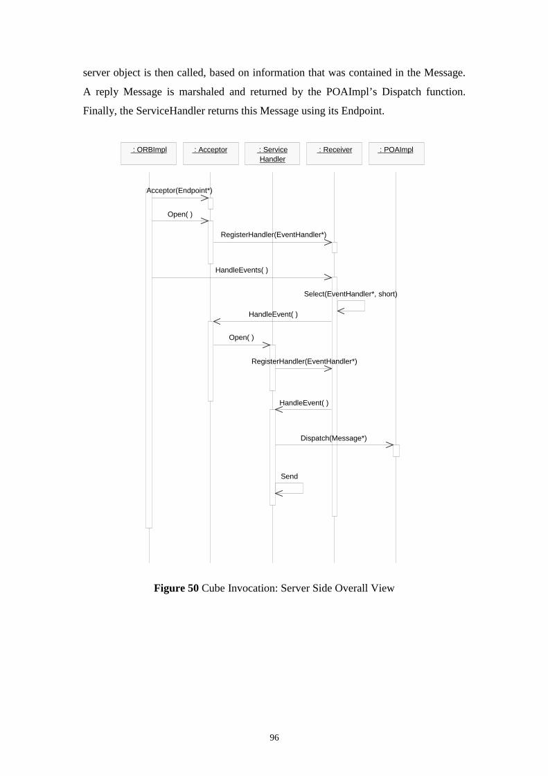
96
server object is then called, based on information that was contained in the Message.
A reply Message is marshaled and returned by the POAImpl’s Dispatch function.
Finally, the ServiceHandler returns this Message using its Endpoint.
Figure 50 Cube Invocation: Server Side Overall View
: Acceptor : Service Handler
: Receiver : POAImpl : ORBImpl
Open( )
RegisterHandler(EventHandler*)
HandleEvents( )
Select(EventHandler*, short)
HandleEvent( )
Open( )
RegisterHandler(EventHandler*)
HandleEvent( )
Dispatch(Message*)
Send
Acceptor(Endpoint*)
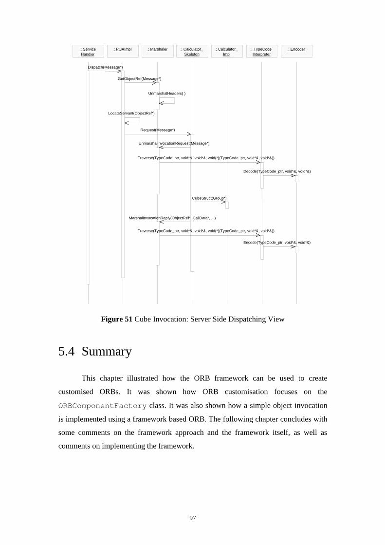
97
Figure 51 Cube Invocation: Server Side Dispatching View
5.4 Summary
This chapter illustrated how the ORB framework can be used to create
customised ORBs. It was shown how ORB customisation focuses on the
ORBComponentFactory class. It was also shown how a simple object invocation
is implemented using a framework based ORB. The following chapter concludes with
some comments on the framework approach and the framework itself, as well as
comments on implementing the framework.
: Service Handler
: POAImpl : Marshaler : Calculator_ Skeleton
: Calculator_ Impl
: TypeCode Interpreter
: Encoder
Dispatch(Message*)
GetObjectRef(Message*)
LocateServant(ObjectRef*)
Request(Message*)
UnmarshalInvocationRequest(Message*)
Traverse(TypeCode_ptr, void*&, void*&, void(*)(TypeCode_ptr, void*&, void*&))
Decode(TypeCode_ptr, void*&, void*&)
CubeStruct(Group*)
MarshalInvocationReply(ObjectRef*, CallData*, ...)
Traverse(TypeCode_ptr, void*&, void*&, void(*)(TypeCode_ptr, void*&, void*&))
Encode(TypeCode_ptr, void*&, void*&)
UnmarshalHeaders( )
98
Chapter 6
Conclusion
6.1 Introduction
The objective of this chapter is to provide some concluding remarks about the design
of the ORB framework. First, some problems regarding the framework approach in
general are described, and how they relate to the ORB framework specifically. Next,
some specific problems encountered with the design of the framework are detailed.
Finally, a possible approach to implementing and extending the framework is
described.
6.2 Problems with the framework approach
Problems typically encountered when using the framework approach have
already been introduced in Chapter 3. This section reiterates some of these, and
relates them to the ORB framework design.
Because a framework is developed with a “one fits all” philosophy, the development
effort required is much larger than that for an ordinary application in the same
domain. The knowledge required from the developers essentially needs to cover the
entire application domain. In the case of the ORB framework, this is especially true.
Developing a framework for building customisable ORBs that really covers the entire
domain of CORBA based middleware is a nontrivial task, since many different
application scenarios can be encountered. To create an ORB specifically aimed at a
particular scenario, in itself, requires a large effort. An example of this is TAO, the
99
ACE ORB, described in Chapter 3, the design and implementation of which has
required a large effort. Yet TAO is aimed at one specific scenario, that of real time
applications. The development of an ORB framework hoping to provide real time
functionality corresponding to that of TAO would require at least the amount of effort
that went into TAO’s development, but much more if it were to cater for other
scenarios as well.
Another problem associated with frameworks relates to their use. The learning curve
required by application programmers who want to use the framework to build
applications based on it is quite large. It is larger for a whitebox framework than for a
blackbox framework. The ORB framework described in this project is a whitebox
framework and certainly would require the user’s insight if he or she were to build
ORBs with it. The principal reason for this is that the framework is mainly based on
inheritance, which requires familiarity with the classes from which one inherits.
As a consequence of this problem frameworks require a large amount of
documentation about their design, inner workings, and use. Again, this contributes to
the overall development effort, though it might be argued that any software project
should be well documented, be it a simple application or a complex framework.
Since frameworks generally control the flow of execution of applications built using
them, problems can occur when attempts are made to combine two or more
framework into an application. This problem is also known as architectural mismatch.
With an implementation of the ORB framework, this might occur when, for example,
an attempt is made to provide a graphical user interface (GUI) using a framework
designed for this purpose. For example, the Microsoft Foundation Classes (MFC)
provide an application framework for the creation of Microsoft Windows based GUIs.
This framework provides its own architectural model, the Document-View
architecture, and could thus create problems in combination with the ORB
framework.
Related to the fact that a framework generally determines the flow of control within
an application built with it, is that debugging is made more difficult in such
applications. In an implementation of the ORB framework this would be compounded
by the fact that an application built using a framework based ORB would be
distributed between client and server ORBs.
Because all applications built using a framework follow one architectural model, an
application built using a framework might not be as efficient as a similar application
100
that was purpose built. In other words, the performance of an application from an
execution speed point of view may not be as good as that of a purpose built
application. This is due to the fact that because of the required generality and
flexibility, a framework may use a lot of indirection. An example of such indirection
in the ORB framework is the creation of concrete Endpoints. Instead of using the
Invoker to create Endpoints directly, it delegates this task to the EndpointManager,
which, in turn, delegates this task to the EndpointCreator. Were it known at
framework design time that all Endpoints should be SocketsEndpoints with no
caching functionality, then all Endpoints could be instantiated in Invoker directly.
There is a direct relationship between increased indirection and increased flexibility.
Finally, the maintainability and extensibility of frameworks affects the applications
built with them. If a framework needs to be extended or modified, these modifications
should remain compatible with previous applications built with the framework. In the
case of the ORB framework, if ORBs are created using an implementation of the
framework, then future versions of the framework should allow those existing ORBs
to be recompiled and work correctly. This is especially important when a number of
new concrete classes, concrete Endpoints, for example, have been implemented in
order to provide additional behaviour. A new version of the ORB framework should
ensure that any such classes that were written for previous versions of the framework
will still work.
6.3 Implementing the framework
It was beyond the scope of this project to provide an actual implementation of
the ORB framework. A number of issues need to be considered before embarking on
an implementation project for the framework.
The implementation language should be an object oriented language such as
Java or C++. For performance reasons C++ might be preferred over Java. Since Java
uses a Virtual Machine (VM), effectively translating Java byte code at runtime, the
performance of a framework implemented in Java may be inferior to one implemented
in C++. At the same time, recent increases in hardware performance have made
application development in Java more favourable, therefore it could be chosen as a
suitable implementation language for the framework.
101
Included in the Java language is the provision for concurrent programming. In
C++, native operating system calls would need to be used to implement multithreaded
programming. This is in addition to the fact that Java is operating system independent,
whereas C++ effectively is OS dependent and needs to be recompiled for each
specific platform.
As regards operating systems and platforms, it is really up to the implementor
of the framework to decide which is suitable. This depends on the available
development tools, compilers, and programming experience. Obviously, the nature of
the framework suggests that the more operating systems and platforms are supported
by a particular development effort, the better.
Finally, there is the question of what is needed for a minimum implementation
of the framework. The answer to this is that essentially one concrete class is required
for each abstract class that has been defined in the framework. An exception to this
are any of the EndpointDecorator classes, as they are needed only for the provision of
extra functionality to an Endpoint.
A point to note when implementing the framework is that it is not set in stone,
and modifications might be required in order to produce an actual implementation. It
is possible that the implementor discovers alternative designs for parts of the
framework which would facilitate an implementation. These should, by all means, be
explored.
6.4 Summary
This chapter provided some concluding remarks about the design of the ORB
framework. Problems regarding framework design in general were discussed, as well
as problems in relation to the design of the ORB framework. Finally, some points
were made about a possible implementation of the ORB framework
102
Bibliography
[Ale77] C. Alexander, S. Ishikawa, M. Silverstein. A Pattern Language. OxfordUniversity Press, New York, 1977.
[Bec94] K. Beck, R. Johnson. Patterns Generate Architectures. In EuropeanConference on Object-Oriented Programming, pages 139-149, Bologna, Italy, July1994. Springer Verlag.
[Cam92] R. Campbell, N. Islam, P. Madany. Choices, Frameworks and Refinement.Computing Systems, Vol. 5, No. 3, Summer 1992.
[Che97] L. Chen, T. Suda. Designing Mobile Computing Systems Using DistributedObjects. In IEEE Communications Magazine, February 1997.
[Dem96] S. Demeyer, T. Meijler, O. Nierstrasz, P. Steyaert. Design Guidelines forTailorable Frameworks. Submitted to Communications of the ACM, Special Issue onObject-Oriented Application Frameworks, Vol. 40, No. 10, October 1997.
[Fay97] M. Fayad, D. Schmidt. Object-Oriented Application Frameworks. Guesteditorial in Communications of the ACM, Special Issue on Object-OrientedApplication Frameworks, Vol. 40, No. 10, October 1997.
[Gam95] E. Gamma, R. Helm, R. Johnson, J. Vlissides. Design Patterns: Elements ofReusable Object-Oriented Software. Addison-Wesley, 1995.
[Joh88] R. Johnson, B. Foote. Designing Reusable Classes. Journal of Object-Oriented programming, June/July 1988.
[Joh91] R. Johnson, V. Russo. Reusing Object-Oriented Designs. Technical ReportUIUCDCS 91-1696 University of Illinois, May 1991.
[Joh92] R. Johnson. Documenting Frameworks using Patterns. In Proceedings of the7th Conference on Object Oriented Programming Systems, Languages, andApplications, Vancouver, Canada, 1992.
[Kos] K. Koskimies, H Mossenbock. Designing a Framework by StepwiseGeneralisation. Institute of Computer Science, Johannes Kepler University Linz,Austria.
[Maf95a] S. Maffeis. Adding Group Communication and Fault-Tolerance to CORBA.USENIX Association Conference on Object-Oriented Technologies (COOTS), June1995.
103
[Maf95b] S. Maffeis. Run-Time Support for Object-Oriented DistributedProgramming. PhD Thesis, University of Zurich, 1995.
[Maf97] S. Maffeis, D. Schmidt. Constructing Reliable Distributed CommunicationSystems with CORBA. In IEEE Communications Magazine, February 1997.
[Rob97] D. Roberts, R. Johnson. Evolving Frameworks: A Pattern Language forDeveloping Object-Oriented Frameworks. In Martin, Riehle, Buschmann. PatternLanguages of Program Design 3. Addison-Wesley, 1997.
[She96] G. Shepherd, S. Wingo. MFC Internals. Addison-Wesley, 1996.
[Sch97] D. Schmidt, A. Gokhale, T. Harrison, G. Parulkar. A High-Performance EndSystem Architecture for Real-Time CORBA.
[Sch98] D.Schmidt, C. Cleeland. Applying Patterns to Develop Extensible andMaintainable ORB Middleware. 1998
[Vin97] S. Vinoski. CORBA: Integrating Diverse Applications Within DistributedHeterogeneous Environments. In IEEE Communications Magazine, February 1997.