Embed Size (px)
Citation preview
IOSR Journal of Electrical and Electronics Engineering (IOSR-JEEE)
e-ISSN: 2278-1676,p-ISSN: 2320-3331, Volume 9, Issue 4 Ver. I (Jul – Aug. 2014), PP 46-52 www.iosrjournals.org
www.iosrjournals.org 46 | Page
A Fuzzy Logic Speed Controller for Separately Excited Dc Motor
and Its Comparison with PID Speed Controller
1Deepshikha,
2Dr. Ramesh Kumar
Department of Electrical Engineering, NIT Patna, Patna, Bihar- 800005
Abstract: DC motors are widely used in industrial and household applications as they provide benefits of high
performance response, high efficiency, high torque and lower volume. This paper proposes the idea of
implementing fuzzy logic controller to control the speed of separately excited DC motor. It provides an overview
of performance with PID controller and fuzzy logic controller. Though PID controller improves both transients
and steady state response characteristics with reduced rise time and steady state error, yet it has limitations of
tuning its parameters and unsatisfactory control characteristics. Fuzzy logic can be described simply as
computing words and can be designed without knowing the exact mathematical model of the process. Initially
these controllers are designed and then tuned to analyze the performance of DC motor. Then the speed response
of fuzzy logic is compared with the response achieved by PID controller. The experimental results prove that the
control characteristic with fuzzy logic is better than that with the conventional PID controller. The modeling of separately excited DC motor and implementation of the two controllers is performed on software
MATLAB/SIMULINK.
Keywords: DC motor, Fuzzy logic controller, membership functions, PID controller, tuned parameters,
I. Introduction
In view of the industrial and household applications, the development of high performance motor
drives is required which should possess good speed control and load regulating response. DC motors fulfill these
characteristics and are simple in design, reliable and cheaper, which make them suitable for applications like
defense, industries, robotics, etc. DC drive circuits are less complex in comparison to AC drives as they include conversion of AC power to DC power only once during its operating time. DC drives are cheaper for higher
power ratings. DC motors are generally used in those applications where wide range of speed control is
required. The motor speed should be controlled in such a way that it gives the desired output response.
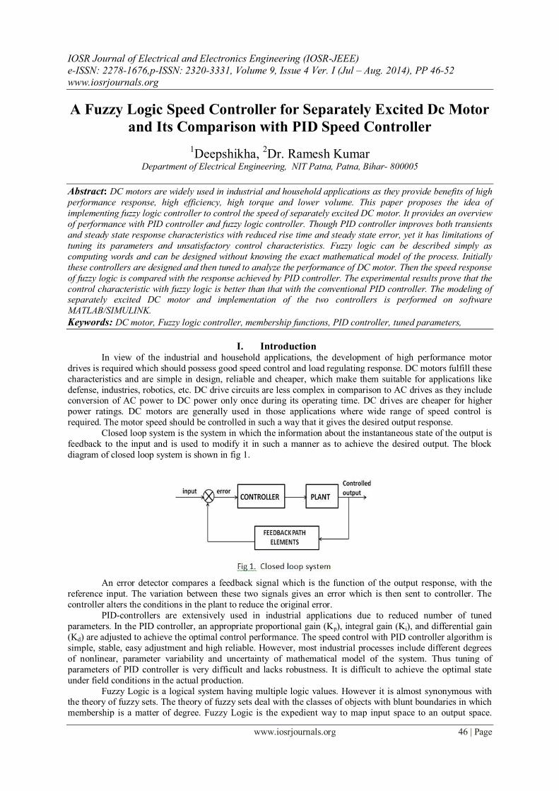
Closed loop system is the system in which the information about the instantaneous state of the output is
feedback to the input and is used to modify it in such a manner as to achieve the desired output. The block
diagram of closed loop system is shown in fig 1.
An error detector compares a feedback signal which is the function of the output response, with the
reference input. The variation between these two signals gives an error which is then sent to controller. The
controller alters the conditions in the plant to reduce the original error.
PID-controllers are extensively used in industrial applications due to reduced number of tuned
parameters. In the PID controller, an appropriate proportional gain (Kp), integral gain (Ki), and differential gain
(Kd) are adjusted to achieve the optimal control performance. The speed control with PID controller algorithm is
simple, stable, easy adjustment and high reliable. However, most industrial processes include different degrees
of nonlinear, parameter variability and uncertainty of mathematical model of the system. Thus tuning of
parameters of PID controller is very difficult and lacks robustness. It is difficult to achieve the optimal state
under field conditions in the actual production.
Fuzzy Logic is a logical system having multiple logic values. However it is almost synonymous with the theory of fuzzy sets. The theory of fuzzy sets deal with the classes of objects with blunt boundaries in which
membership is a matter of degree. Fuzzy Logic is the expedient way to map input space to an output space.
A Fuzzy Logic Speed Controller for Separately Excited Dc Motor and Its Comparison with PID ……
www.iosrjournals.org 47 | Page
Fuzzy logic control has proved to be efficient for complex, non-linear and inaccurately defined processes for
which standard model based control techniques are impractical or impossible[2]. The applications of Fuzzy
Logic are usually for household appliances such as washing machine and rice cooker. Fuzzy logic is also used in
industrial applications like cement kilns, underground trains, robotics, etc.
The objective of this paper is that it shows the speed performance with design the fuzzy logic controller
to control a speed of motor for keeping the motor speed to be constant when the load varies. This paper presents
design of separately excited DC motor and then implementation of Fuzzy logic controller and PID controller to compare the response of speed of the motor.
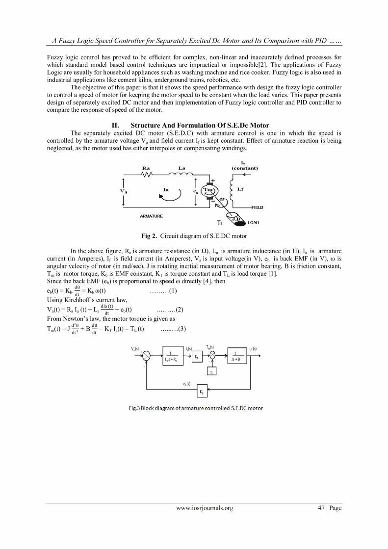
II. Structure And Formulation Of S.E.Dc Motor The separately excited DC motor (S.E.D.C) with armature control is one in which the speed is
controlled by the armature voltage Va and field current If is kept constant. Effect of armature reaction is being
neglected, as the motor used has either interpoles or compensating windings.
Fig 2. Circuit diagram of S.E.DC motor
In the above figure, Ra is armature resistance (in Ω), La is armature inductance (in H), Ia is armature
current (in Amperes), If is field current (in Amperes), Va is input voltage(in V), eb is back EMF (in V), ω is
angular velocity of rotor (in rad/sec), J is rotating inertial measurement of motor bearing, B is friction constant,
Tm is motor torque, Kb is EMF constant, KT is torque constant and TL is load torque [1].
Since the back EMF (eb) is proportional to speed ω directly [4], then
eb(t) = Kb. dθ
dt = Kb ω(t) ………(1)
Using Kirchhoff‟s current law,
Va(t) = Ra Ia (t) + La dIa (t)
dt + eb(t) ………(2)
From Newton‟s law, the motor torque is given as
Tm(t) = J d²θ
dt ² + B
dθ
dt = KT Ia(t) – TL (t) …...…(3)
A Fuzzy Logic Speed Controller for Separately Excited Dc Motor and Its Comparison with PID ……
www.iosrjournals.org 48 | Page
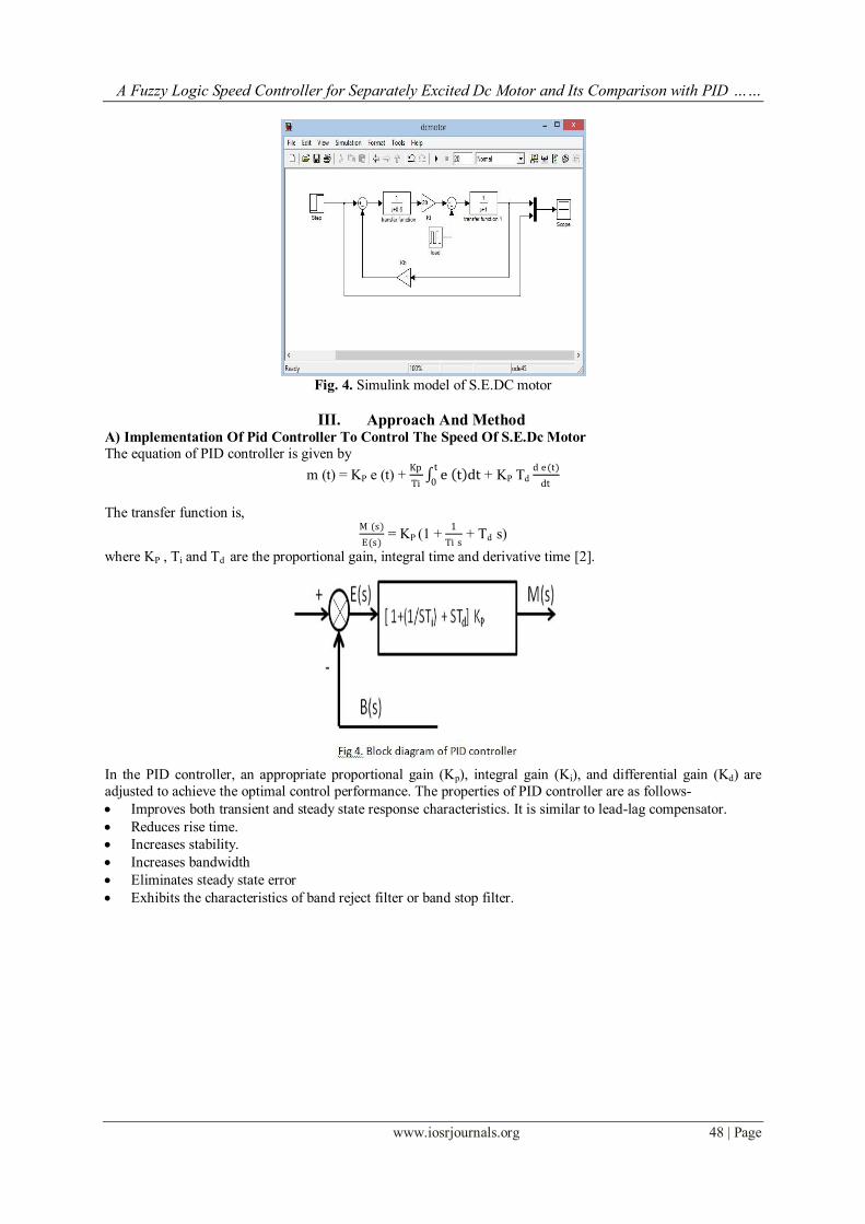
Fig. 4. Simulink model of S.E.DC motor
III. Approach And Method
A) Implementation Of Pid Controller To Control The Speed Of S.E.Dc Motor
The equation of PID controller is given by
m (t) = KP e (t) + Kp
Ti e t dt
t
0 + KP Td
d e(t)
dt
The transfer function is, M (s)
E(s) = KP (1 +
1
Ti s + Td s)
where KP , Ti and Td are the proportional gain, integral time and derivative time [2].
In the PID controller, an appropriate proportional gain (Kp), integral gain (Ki), and differential gain (Kd) are
adjusted to achieve the optimal control performance. The properties of PID controller are as follows-
Improves both transient and steady state response characteristics. It is similar to lead-lag compensator.
Reduces rise time.
Increases stability.
Increases bandwidth
Eliminates steady state error
Exhibits the characteristics of band reject filter or band stop filter.
A Fuzzy Logic Speed Controller for Separately Excited Dc Motor and Its Comparison with PID ……
www.iosrjournals.org 49 | Page
Fig 5 Simulink model of PID controller
Fig 6. Simulink model of S.E.DC motor with PID controller
B) Implementation Of Fuzzy Logic Controller To Control The Speed Of S.E.Dc Motor
Fuzzy logic controller generates fuzzy rules by converting linguistic control strategy into an automatic
strategy which controls the behaviour of the system. Fuzzy logic provides a simple way to draw specific conclusion from ambiguous imprecise information.
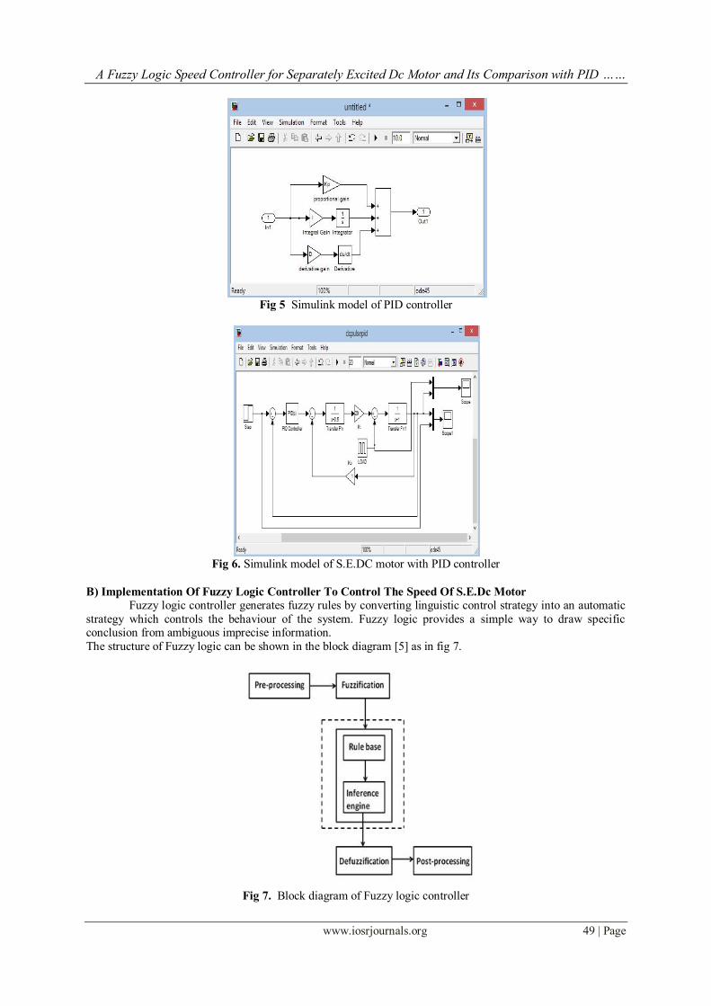
The structure of Fuzzy logic can be shown in the block diagram [5] as in fig 7.
Fig 7. Block diagram of Fuzzy logic controller
A Fuzzy Logic Speed Controller for Separately Excited Dc Motor and Its Comparison with PID ……
www.iosrjournals.org 50 | Page
Pre-processing block deals with inputs which may be in the form of hard or crisp measurement from
some measuring equipments rather than linguistics.
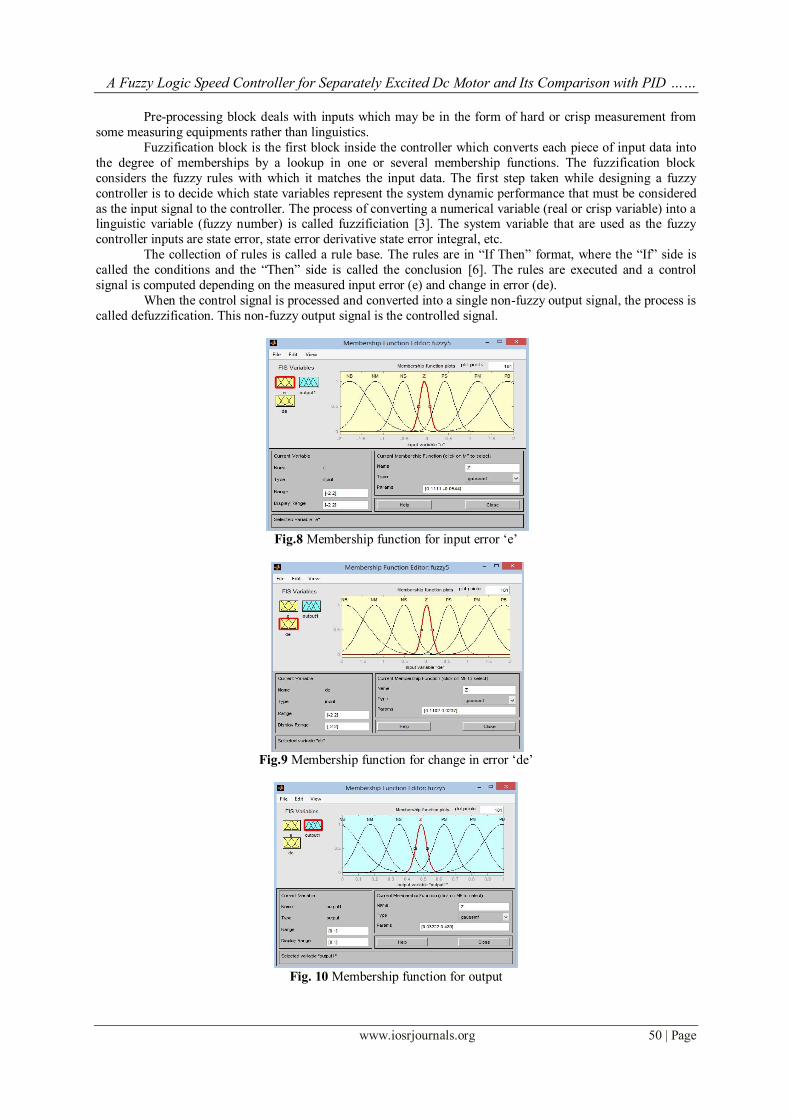
Fuzzification block is the first block inside the controller which converts each piece of input data into
the degree of memberships by a lookup in one or several membership functions. The fuzzification block
considers the fuzzy rules with which it matches the input data. The first step taken while designing a fuzzy
controller is to decide which state variables represent the system dynamic performance that must be considered
as the input signal to the controller. The process of converting a numerical variable (real or crisp variable) into a linguistic variable (fuzzy number) is called fuzzificiation [3]. The system variable that are used as the fuzzy
controller inputs are state error, state error derivative state error integral, etc.
The collection of rules is called a rule base. The rules are in “If Then” format, where the “If” side is
called the conditions and the “Then” side is called the conclusion [6]. The rules are executed and a control
signal is computed depending on the measured input error (e) and change in error (de).
When the control signal is processed and converted into a single non-fuzzy output signal, the process is
called defuzzification. This non-fuzzy output signal is the controlled signal.
Fig.8 Membership function for input error „e‟
Fig.9 Membership function for change in error „de‟
Fig. 10 Membership function for output
A Fuzzy Logic Speed Controller for Separately Excited Dc Motor and Its Comparison with PID ……
www.iosrjournals.org 51 | Page
In this paper, the rule editor consists of 49 rules, based on which Fuzzy Logic controller operates to
give the desired result. These 49 rules are derived from the rule database [7] given as follows:
e
de
NB
NM
NS
Z
PS
PM
PB
NB
NB
NB
NB
NB
NM
NS
Z
NM
NB
NB
NB
NM
NM
Z
PS
NS
NB
NB
NM
NS
Z
PS
PM
Z
NB
NM
NM
Z
PM
PM
PB
PS
NM
NS
Z
PS
PM
PB
PB
PM
NS
Z
PM
PM
PB
PB
PB
PB
Z
PS
PM
PB
PB
PB
PB
Table I. Fuzzy base rule
where NB, NM, NS, Z, PS, PM and PB are negative big, negative medium, negative small, zero, positive small,
positive medium and positive big. These are the membership functions of the inputs and output.
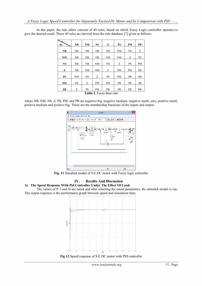
Fig. 11 Simulink model of S.E.DC motor with Fuzzy logic controller
IV. Results And Discussion
A) The Speed Response With Pid Controller Under The Effect Of Load.
The values of P, I and D are tuned and after selecting the tuned parameters, the simulink model is run.
The output response is the performance graph between speed and simulation time.
Fig 12 Speed response of S.E.DC motor with PID controller
A Fuzzy Logic Speed Controller for Separately Excited Dc Motor and Its Comparison with PID ……
www.iosrjournals.org 52 | Page
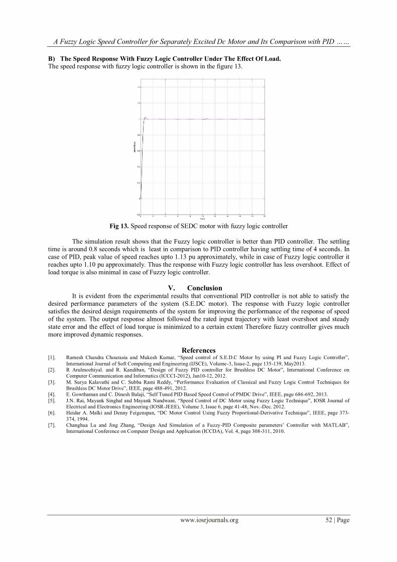
B) The Speed Response With Fuzzy Logic Controller Under The Effect Of Load.
The speed response with fuzzy logic controller is shown in the figure 13.
Fig 13. Speed response of SEDC motor with fuzzy logic controller
The simulation result shows that the Fuzzy logic controller is better than PID controller. The settling
time is around 0.8 seconds which is least in comparison to PID controller having settling time of 4 seconds. In
case of PID, peak value of speed reaches upto 1.13 pu approximately, while in case of Fuzzy logic controller it
reaches upto 1.10 pu approximately. Thus the response with Fuzzy logic controller has less overshoot. Effect of
load torque is also minimal in case of Fuzzy logic controller.
V. Conclusion
It is evident from the experimental results that conventional PID controller is not able to satisfy the
desired performance parameters of the system (S.E.DC motor). The response with Fuzzy logic controller
satisfies the desired design requirements of the system for improving the performance of the response of speed
of the system. The output response almost followed the rated input trajectory with least overshoot and steady
state error and the effect of load torque is minimized to a certain extent Therefore fuzzy controller gives much
more improved dynamic responses.
References [1]. Ramesh Chandra Chourasia and Mukesh Kumar, “Speed control of S.E.D.C Motor by using PI and Fuzzy Logic Controller”,
International Journal of Soft Computing and Engineering (IJSCE), Volume-3, Issue-2, page 135-139, May2013.
[2]. R Arulmozhiyal. and R. Kandiban, “Design of Fuzzy PID controller for Brushless DC Motor”, International Conference on
Computer Communication and Informatics (ICCCI-2012), Jan10-12, 2012.
[3]. M. Surya Kalavathi and C. Subba Rami Reddy, “Performance Evaluation of Classical and Fuzzy Logic Control Techniques for
Brushless DC Motor Drive”, IEEE, page 488-491, 2012.
[4]. E. Gowthaman and C. Dinesh Balaji, “Self Tuned PID Based Speed Control of PMDC Drive”, IEEE, page 686-692, 2013.
[5]. J.N. Rai, Mayank Singhal and Mayank Nandwani, “Speed Control of DC Motor using Fuzzy Logic Technique”, IOSR Journal of
Electrical and Electronics Engineering (IOSR-JEEE), Volume 3, Issue 6, page 41-48, Nov.-Dec. 2012.
[6]. Heidar A. Malki and Denny Feigenspan, “DC Motor Control Using Fuzzy Proportional-Derivative Technique”, IEEE, page 373-
374, 1994.
[7]. Changhua Lu and Jing Zhang, “Design And Simulation of a Fuzzy-PID Composite parameters‟ Controller with MATLAB”,
International Conference on Computer Design and Application (ICCDA), Vol. 4, page 308-311, 2010.