Embed Size (px)
Citation preview

A GLOBAL MODEL BASED ENERGY MANAGEMENT SYSTEMAPPLIED TO THE CANOPEA BUILDING
Yanis Hadj Said2, Stephane Ploix2, Sylvain Galmiche3, Benoit Lechat3,Adel Djellouli1, Tristan Scheid1, Stephane Bergeon3, Xavier Brunotte3
1ENSE3, Grenoble Institute of Technology, France2G-SCOP lab, CNRS UMR 5272, Grenoble Institute of Technology, France
3Vesta-System Cie, Grenoble, France
ABSTRACTThis paper deals with the global model based antic-ipative energy management system adapted for theCANOPEA building prototype proposed by the teamRhone-Alpes for the Solar Decathlon Europe con-test. It presents a practical application of theoreti-cal studies originally developed in Grenoble Researchlabs (G-SCOP, G2Elab and LIG) and improved by theVesta-System company. The different configurationsof the building system including the envelope withthe HVAC system, a battery and domestic appliancesare presented: shutters, water storage, a temperaturephase shifter, an air/air heat pump, an water/waterheat pump, hybrid panels, The system, able to adaptto many different contexts to harvest the maximumenergy, is so complex that it is difficult for a humanto define the best configuration according to weathercontext and occupant activities. The proposed energymanagement system embeds a CANOPEA model con-nected to actual measurements, forecasts, realtime en-ergy costs and occupant demands collected thanks toan Android tablet. It is able to support decision regard-ing the day ahead best CANOPEA configurations witha one-hour resolution.
INTRODUCTIONA Rhone-Alpes team (sol), led by the Ecole Na-tionale Suprieure d’Architecture de Grenoble, has de-signed and constructed a building prototype, namedCANOPEA, for the Solar Decathlon Europe 2012 con-test (sde). The Grenoble Institute of Technology, witha partnership with Vesta-System and UXP companies,has been in charge of designing an energy manage-ment system that was actually used as an action ad-viser. This paper depicted the solution that has beendesigned and used during the contest won by theCANOPEA prototype. The implemented building en-ergy management system (BEMS) is an application oftheoretical researches summarized in (Ha et al., 2012).A home automation system basically consists ofhousehold appliances linked via a communicationnetwork allowing interactions for control purposes(Palensky and Posta, 1997). Thanks to this network,a load management mechanism can be carried out bydistributed control (Wacks, 1993). Energy manage-ment allows inhabitants to set up the best buildingconfiguration in order to reduce energy expenses but
also to adjust power consumption according to ex-pected comfort and energy price variation. When priceis rising, it is possible to decide to delay some ser-vices, to modify the envelope configuration (blinds,shutters,...), to reduce some set points or to modifythe state of HVAC appliances. Occupants can man-age it on their own but an energy management systemprovide a helpful support, especially when issues be-come complex, to better exploit the system flexibili-ties but also the occupant tolerances regarding com-fort. It helps to reach dominant (according to Pareto’sdefinition) compromise between energy cost and com-fort. A global solution for the household load man-agement problem has been proposed in (Ha et al.,2006). Some authors considered in particular the man-agement of local production means and storage sys-tems (Henze and Dodier, 2003; Foggia, 2009; Eynard,2010). Energy load management has been conceptu-alized in (Ha et al., 2006). A dynamic programmingapproach has been proposed (Riffoneau, 2010). Otherresearchers used a multi-agent approach (Penya, 2003;Negenborn, 2007; ?). But, a general approach of theenergy management in dwellings yields new issues:
• solving energy management problems whereuncertainties are predominant. A three layer ar-chitecture has been proposed in (Duy Ha et al.,2006; Ha et al., 2008b). Uncertainties can alsobe taken into account during the optimizationstep (Ha et al., 2008a).
• solving large dimension optimization problems.It has been tackled using a mixed integer linearprogramming approach that can manage thou-sands of binary and continuous variables. Waysof transforming an energy management probleminto a MILP, which is a regular problem, havebeen shown in (Ha et al., 2009, 2010).
• solving singular problems. Multi-agent ap-proaches have been used to manage services thatcan only be modeled by nonlinear equations in(Abras et al., 2006, 2007, 2010; Elmahaiawyet al., 2010).
• generating dynamically the energy managementproblems to solve them because each dwellingis unique and evolving. Dynamic optimizationproblem generation has been studied (Warkozeket al., 2009). Software architecture and solvingprocess have been depicted (Ploix et al., 2010).
Proceedings of BS2013: 13th Conference of International Building Performance Simulation Association, Chambéry, France, August 26-28
- 2185 -

The CANOPEA energy management problem is firstlystated before detailing how the implemented BEMShas been customized. The system architecture is thendiscussed and example of results are presented. Thepaper finishes with the Android tablet application thathas been designed to support interaction with occu-pants of the CANOPEA building.
PROBLEM STATEMENTFigure 1 is a picture of the finalized CANOPEA build-ing project in Madrid. The building system with itsflexibilities can be decomposed into 4 parts.
Figure 1: The CANOPEA prototype in Madrid duringthe contest
The HVAC systemThe different parts of the HVAC system are illustratedin figure 2. It is composed of an water/water anda main air/air heat pump manufactured by the Nilancompany: warm or cool air can be pulsed into theliving area but also warm or cool water can circulateinto a radiant ceiling made of earth panels. The mainair/air heat pump can produce domestic hot water us-ing a electric resistance but the air/water heat pumpcan also support the domestic water heating process.This part is modeled by the Building Energy Man-agement System (BEMS) but it is automatically man-aged by the Nilan system. A thermal storage tank withphase change material can store and restore heat to theearth panels thanks to a reversible water circuit withelectric circulators. The air flow that feeds the air/airheat pump can come directly from outside or from atemperature phase shifter developed by the Universityof Geneva. It is made of fans and of materials withan important inertia and, providing that the fans arerunning, it provides a 12 hours shift of the outdoortemperature at the output that can be connected to theair/air heat pump to increase its efficiency. The wa-ter/water heat pump gets heat from hybrid solar panelslocated on the roof or from a air/water heat exchangerlocated outside of the building that emulates a districtwarm water loop.The heat provided by the heat pumps and the con-figurations of the HVAC systems can be adjusted.16(2 ⇥ 8) authorized configurations have been con-
sidered. The number of configurations is doubled be-cause in each configuration, the main air/air heat pumpcan be fed up directly by outdoor air or by the 12 hourshifted air provided by the temperature phase shifter.
Figure 2: An example of configuration of the HVACsystem
The configurations are:configuration 1.1 and 2.1 The water is circulating
in the earth panels but there is no exchangewith the thermal storage tanks. The water/wa-ter heat pump is off. The air/air heat pump is onand pulses conditioned air into the first floor ofCANOPEA (which is the only temperature con-trolled zone).
configuration 1.2 and 2.2 Same configuration thanbefore except that the warm water coming outfrom the earth panels is injected to the top ofthe storage tank while cool water is taken at thebottom to be injected into the earth panels.
configuration 1.3 and 2.3 Same as x.2 except thatthe exchange with the storage tank is reverted.Warm water is collected from storage tank andintroduced into the water circuit of ceiling.
configuration 1.4 and 2.4 Both heat pumps are on.Conditioned air is pulsed into CANOPEA. Hotwater is taken for the top of the storage tank andis injected into the earth panels. The water/waterheat pump is fed up with hot water taken fromhybrid solar panel but also from water/air heatexchanger. The water/water heat pump supportsthe production of domestic hot water carried outby the main air/air heat pump. It also injects hotwater into the heat storage tank.
configuration 1.5 and 2.5 Same than x.4 but with-out supporting the production of domestic hotwater.
configuration 1.6 and 2.6 Same than x.4 except thatdirections of water circulations are reverted. Hotwater is coming out from earth panel and in-jected to the thermal storage tank. Cool water iscollected from the hybrid solar panels but alsofrom the air/water heat exchanger and it is usedby the water/water heat pump that feeds up thestorage tank with cool water and supports theheating of domestic hot water.
Proceedings of BS2013: 13th Conference of International Building Performance Simulation Association, Chambéry, France, August 26-28
- 2186 -
configuration 1.7 and 2.7 Same than x.6 except thatair/water heat exchanger is not used.
configuration 1.8 and 2.8 Same than x.6 except thathybrid solar panels are not used.
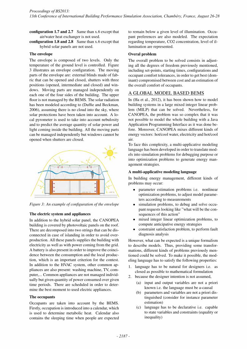
The envelopeThe envelope is composed of two levels. Only thetemperature of the ground level is controlled. Figure3 illustrates an envelope configuration. The movingparts of the envelope are: external blinds made of fab-ric that can be opened and closed, shutters with threepositions (opened, intermediate and closed) and win-dows. Moving parts are managed independently oneach one of the four sides of the building. The upperfloor is not managed by the BEMS. The solar radiationhas been modeled according to (Duffie and Beckman,2006), assuming there is no cloud into the sky, wheresolar protections have been taken into account. A lo-cal pyrometer is used to take into account nebulosityand to predict the average quantity of solar power andlight coming inside the building. All the moving partscan be managed independently but windows cannot beopened when shutters are closed.
Figure 3: An example of configuration of the envelope
The electric system and appliancesIn addition to the hybrid solar panel, the CANOPEAbuilding is covered by photovoltaic panels on the roof.There are decomposed into two strings that can be dis-connected in case of islanding in order to avoid over-production. All these panels supplies the building withelectricity as well as with power coming from the grid.A battery is also present in order to improve the coinci-dence between the consumption and the local produc-tion, which is an important criterion for the contest.In addition to the HVAC system, other common ap-pliances are also present: washing machine, TV, com-puter,... Common appliances are not managed individ-ually but given quantity of power consumed over giventime periods. There are scheduled in order to deter-mine the best moment to used electric appliances.
The occupantsOccupants are taken into account by the BEMS.Firstly, occupation is introduced into a calendar, whichis used to determine metabolic heat. Calendar alsocontains the sleeping time when people are expected
to remain below a given level of illumination. Occu-pant preferences are also modeled. The expectationregarding temperature, CO2 concentration, level of il-lumination are represented.
Overal problemThe overall problem to be solved consists in adjust-ing all the degrees of freedom previously mentioned,including set-points, starting times, configurations andoccupant comfort tolerances, in order to get best (dom-inant) compromised between cost and an estimation ofthe overall comfort of occupants.
A GLOBAL MODEL BASED BEMSIn (Ha et al., 2012), it has been shown how to modelbuilding systems in a large mixed integer linear prob-lem (MILP) that can be solved. Nevertheless, forCANOPEA, the problem was so complex that it wasnot possible to model the whole building with a JavaApplication Programming Interface as it was done be-fore. Moreover, CANOPEA mixes different kinds ofenergy vectors: hot/cool water, electricity and hot/coolair.To face this complexity, a multi-applicative modelinglanguage has been developed in order to translate mod-els into simulation problems for debugging purpose orinto optimization problems to generate energy man-agement strategies.
A multi-applicative modeling languageIn building energy management, different kinds ofproblems may occur:
• parameter estimation problems i.e. nonlinearoptimization problems, to adjust model parame-ters according to measurements
• simulation problems, to debug and solve occu-pant requests looking like ”what will be the con-sequences of this action”
• mixed integer linear optimization problems, tocompute anticipative energy strategies
• constraint satisfaction problem, to perform faultdiagnosis analysis
However, what can be expected is a unique formalismto describe models. Thus, providing some transfor-mations, different kinds of problems previously men-tioned could be solved. To make it possible, the mod-eling language has to satisfy the following properties:1. language has to be natural for designers i.e. as
closed as possible to mathematical formulation2. because the designer intention is not assumed,
(a) input and output variables are not a prioriknown i.e. the language must be a-causal
(b) parameters and variables are not a priori dis-tinguished (consider for instance parameterestimation)
(c) language has to be declarative i.e. capableto state variables and constraints (equality orinequality)
Proceedings of BS2013: 13th Conference of International Building Performance Simulation Association, Chambéry, France, August 26-28
- 2187 -

3. language has to be consistent with existing lan-guages, especially close to the a-causal MODEL-ICA language.
Listing 1 MILP representation of an air/air heat pump
i n t i ;v a r i a b l e ( ” c o m p r e s s o r O f f s e t P o w e r : [ 0 . . 1 0 0 0 ] ” ) ;v a r i a b l e ( ” v e n t i l a t i o n P o w e r : [ 0 . . 1 0 0 0 ] ” ) ;f o r ( i =0 ; i<n P e r i o d s ; i ++) {
v a r i a b l e ( ” e l e c t r i c P o w e r [{ i }] i n e l e c t r i c P o w e r : [ 0 . .{ compressorPower } ] ” ) ;v a r i a b l e ( ” i n j e c t e d P o w e r [{ i }] i n i n j e c t e d P o w e r : [�55e8 . . 5 5 e8 ] ” ) ;v a r i a b l e ( ” h o t S o u r c e E n e r g y [{ i }] i n h o t S o u r c e E n e r g y :[�55 e8 . . 5 5 e8 ] ” ) ;v a r i a b l e ( ” c o l d S o u r c e E n e r g y [{ i }] i n c o l d S o u r c e E n e r g y : [�55e8 . . 5 5 e8 ] ” ) ;v a r i a b l e ( ” cop [{ i }] i n cop : [ 1 . . 6 ] ” ) ;v a r i a b l e ( ” compressorPower [{ i }] i n compressorPower : [ 0 . .{ compressorPower } ] ” ) ;v a r i a b l e ( ” hotSourceInTemp [{ i }] i n h e a t S o u r c e I n p u t T e m p e r a t u r e : [ 0 . . 6 e6 ] ” ) ;v a r i a b l e ( ” hotSourceOutTemp [{ i }] i n hotSourceOutTemp : [ 0 . . 6 e6 ] ” ) ;v a r i a b l e ( ” co ldSourceInTemp [{ i }] i n co ldSourceInTemp : [ 0 . . 6 e6 ] ” ) ;v a r i a b l e ( ” coldSourceOutTemp [{ i }] i n coldSourceOutTemp : [ 0 . . 6 e6 ] ” ) ;v a r i a b l e ( ” ou tdoorAi r InTemp [{ i }] i n ou tdoorAi r InTemp : [ 0 . . 6 0 0 ] ” ) ;v a r i a b l e ( ” outdoorAirOutTemp [{ i }] i n outdoorAirOutTemp : [ 0 . . 6 0 0 ] ” ) ;v a r i a b l e ( ” indoorAi r InTemp [{ i }] i n indoorAi r InTemp : [ 0 . . 6 0 0 ] ” ) ;v a r i a b l e ( ” indoorAirOutTemp [{ i }] i n indoorAirOutTemp : [ 0 . . 6 0 0 ] ” ) ;v a r i a b l e ( ” modeOff [{ i }] i n modeOff : {0 . . 1} ” ) ;v a r i a b l e ( ” v e n t i l M o d e [{ i }] i n v e n t i l M o d e : {0 . . 1} ” ) ;v a r i a b l e ( ” heatMode [{ i }] i n heatMode : {0 . . 1} ” ) ;v a r i a b l e ( ” coolMode [{ i }] i n coolMode : {0 . . 1} ” ) ;c o n s t r a i n t ( ” mode[{ i }] i n mode : modeOff [{ i }] + v e n t i l M o d e [{ i }]”+
”+ heatMode [{ i }] + coolMode [{ i }] == 1 ” ) ;/ / d e f i n e c o n n e c t i o n s f o r h o t and c o l d s o u r c e s ( o r zones )
c o n s t r a i n t ( ” modeOff1 [{ i }] i n modeOff1 : hotSourceOutTemp [{ i }] == ”+”{ a i r C a p a⇤e x t e r n a l A i r F l o w}⇤indoorAirOutTemp [{ i}]⇤heatMode [{ i }] ”+”+ {a i r C a p a⇤e x t e r n a l A i r F l o w}⇤outdoorAirOutTemp [{ i}]⇤coolMode [{ i } ] ” ) ;
c o n s t r a i n t ( ” mode1[{ i }] i n mode : hotSourceOutTemp [{ i }]”+”{ == a i r C a p a⇤e x t e r n a l A i r F l o w}⇤indoorAirOutTemp [{ i}]⇤heatMode [{ i }] ”+”+ {a i r C a p a⇤e x t e r n a l A i r F l o w}⇤outdoorAirOutTemp [{ i}]⇤coolMode [{ i } ] ” ) ;
c o n s t r a i n t ( ” mode2[{ i }] i n mode : hotSourceInTemp [{ i }]”+” == {a i r C a p a⇤e x t e r n a l A i r F l o w}⇤i ndoorAi r InTemp [{ i}]⇤heatMode [{ i }] ”+”+ {a i r C a p a⇤e x t e r n a l A i r F l o w}⇤ou tdoorAi r InTemp [{ i}]⇤coolMode [{ i } ] ” ) ;
c o n s t r a i n t ( ” mode3[{ i }] i n mode : coldSourceOutTemp [{ i }]”+” == {a i r C a p a⇤e x t e r n a l A i r F l o w}⇤outdoorAirOutTemp [{ i}]⇤heatMode [{ i }] ”+”+ {a i r C a p a⇤e x t e r n a l A i r F l o w}⇤indoorAirOutTemp [{ i}]⇤coolMode [{ i } ] ” ) ;
c o n s t r a i n t ( ” mode4[{ i }] i n mode : co ldSourceInTemp [{ i }]”+” == {a i r C a p a⇤e x t e r n a l A i r F l o w}⇤ou tdoorAi r InTemp [{ i}]⇤heatMode [{ i }] ”+”+ {a i r C a p a⇤e x t e r n a l A i r F l o w}⇤i ndoorAi r InTemp [{ i}]⇤coolMode [{ i } ] ” ) ;
/ / e n e r g e t i c modelsc o n s t r a i n t ( ” pac1 [{ i }] i n pac : c o l d S o u r c e E n e r g y [{ i }]==”+” coldSourceOutTemp [{ i }] � co ldSourceInTemp [{ i } ] ” ) ;
c o n s t r a i n t ( ” pac2 [{ i }] i n pac : h o t S o u r c e E n e r g y [{ i }]==”+” hotSourceOutTemp [{ i }] � hotSourceInTemp [{ i } ] ” ) ;
c o n s t r a i n t ( ” pac3 [{ i }] i n pac : e l e c t r i c P o w e r [{ i }]==”+” c o l d S o u r c e E n e r g y [{ i }] + h o t S o u r c e E n e r g y [{ i } ] ” ) ;
c o n s t r a i n t ( ” pac4 [{ i }] i n pac : h o t S o u r c e E n e r g y [{ i }]==”+” cop [{ i}]⇤heatMode [{ i}]⇤ e l e c t r i c P o w e r [{ i }]+”+” cop [{ i}]⇤coolMode [{ i}]⇤ e l e c t r i c P o w e r [{ i } ] ” ) ;
c o n s t r a i n t ( ” pac5 [{ i }] i n pac : e l e c t r i c P o w e r [{ i }]==”+” compressorPower [{ i }] � compressorPower [{ i}]⇤modeOff [{ i }] ” +”+ heatMode [{ i}]⇤c o m p r e s s o r O f f s e t P o w e r ”+”+ coolMode [{ i}]⇤c o m p r e s s o r O f f s e t P o w e r ”+”+ v e n t i l M o d e [{ i}]⇤ v e n t i l a t i o n P o w e r ” ) ;
/ / d e f i n e c o n n e c t i o n s f o r h o t and c o l d s o u r c e s ( o r zones )c o n s t r a i n t ( ” f o r c e S o r t i e 4 [{ i }] i n f o r c e S o r t i e 4 : ”+” outdoorAirOutTemp [{ i}]⇤v e n t i l M o d e [{ i }]”+” == indoorAi r InTemp [{ i}]⇤v e n t i l M o d e [{ i } ] ” ) ;
c o n s t r a i n t ( ” f o r c e S o r t i e 5 [{ i }] i n f o r c e S o r t i e 5 : ”+” indoorAirOutTemp [{ i}]⇤v e n t i l M o d e [{ i }]”+” == outdoorAi r InTemp [{ i}]⇤v e n t i l M o d e [{ i } ] ” ) ;
c o n s t r a i n t ( ” f o r c e S o r t i e 8 [{ i }] i n f o r c e S o r t i e 8 : ”+” indoorAirOutTemp [{ i}]⇤modeOff [{ i }] == ”+” indoorAi r InTemp [{ i}]⇤modeOff [{ i } ] ” ) ;
c o n s t r a i n t ( ” f o r c e S o r t i e 9 [{ i }] i n f o r c e S o r t i e 9 : ”+” outdoorAirOutTemp [{ i}]⇤modeOff [{ i }] == ”+” ou tdoorAi r InTemp [{ i}]⇤modeOff [{ i } ] ” ) ;
c o n s t r a i n t ( ” i n j e c t e d P o w e r [{ i }] i n i n j e c t e d P o w e r : ” +” {a i r C a p a⇤ i n t e r n a l A i r F l o w}⇤indoorAirOutTemp [{ i }] ” +”� {a i r C a p a⇤ i n t e r n a l A i r F l o w}⇤i ndoorAi r InTemp [{ i }]== i n j e c t e d P o w e r [{ i } ] ” ) ;
}
Example 1 is a prototype of language that illustrateshow a heat pump can be modeled without a priori in-tention. Each variable is defined by a label and by avalue domain, which can be an continuous interval ora set of integers. Each variable may belong to a vari-able set in order to facilitate the display by gatheringvariables. For instance, in example 1, all the variableselectricPowers related to given time periods are gath-ered into the variable set electricPower. Constraintsbetween variables are named and may also be gath-ered into constraint sets. A constraint is an a-causalrelation between some variables. Parameters are notdefined explicitly: they correspond to variables whosevalue domain is restricted to a single value a poste-riori according to the usage of the model. For in-
stance, the coefficient of performance (COP) can betransformed into a parameter by restriction to a singlevalue to generate energy management strategies, it canalso be modeled by an integer variable to model dif-ferent values of COP or remains a continuous intervalfor parameter estimation purpose.Regarding CANOPEA, models have been used forsimulation with a debug purpose but also for MILP op-timization for energy management purpose. For thesetwo purposes, the same CPLEX MILP solver havebeen used. Therefore, model has to become linear butproducts like outdoorAirOutTemp[i]*ventilMode[i]are not. Nevertheless, some linearization patterns,given in (Ha et al., 2012), are automatically used tolinearized these kinds of nonlinearities. The followinglinearization patterns are automatically applied recur-sively:
• product of n binary variables• semi-continuous product of a binary variable
and a continuous one• logical implication or equivalence• minimum or maximum• linearization of nonlinear function by a stepwise
function• linearization of ordinary differential equations
A composition mechanismSetting up a model for CANOPEA is not easy to man-age because there is a huge quantity of components inthe system. To set up such a system, the validation hasbeen done step by step in modeling each componentindependently such as in figure 4. Then componentscan be built step by step starting by restricting somevariables as inputs to generate simulations. Once thesimulation is meaningful, some variables are relaxedin order to yield optimization problems. Then a largercomposition is done by adding new components. Acomposition is obtained by instantiating model com-ponents, restricting parameter variables, by connect-ing variables between components using equality con-straints. Depending on the problem to be solved, acriterion to be optimized may be added.
occupationCalendar
sunImpactOnSolarPanel
sunImpactOnWindows
phaseShifter
compactP-PAC
hybridPanel
main-PAC
thermalStorageTank
hotWaterThermalStorageTank
waterLaw
earthPanel
artificialLighting
Room
thermalComfortCO2comfort
lightingComfort
northThreeStateShutter
southThreeStateShutter
eastThreeStateShutter
westThreeStateShutter
pvOnFirstInverter
pvOnSecondInverter
pvtOnSecondInverter
incurredConsumption
powerSupplierbattery
controllableConsumption
weather
thermalEquilibrium
sleepingTime
totalLighting
solarPowerInM2
electricEquilibrium
objectivesolarRadiation
Figure 4: Structural representation of the CANOPEAmodel used for energy management
Proceedings of BS2013: 13th Conference of International Building Performance Simulation Association, Chambéry, France, August 26-28
- 2188 -

For the CANOPEA project, the Vesta-System com-pany have modified the language proposed in program1 in order to become closer to the MODELICA lan-guage, getting inspired by the SML language proposedby researchers from G2Elab.
SYSTEM ARCHITECTUREThe architecture of the energy management systemused for CANOPEA is presented in this section. Anetworks of more than one hundred of sensors andactuators, measuring comforts, physical variables inthe HVAC system and consumption of electric appli-ances, modifying artificial lighting, the behavior of theHVAC system have been set up by the IUT 1 GEII ofGrenoble. In addition, some recent prototypes of sen-sors based on the Zigbee Green Power protocol havebeen provided by Schneider Electric. A part of theHome Abstraction Layer developed within the RE-ACTIVHOME ANR project (REACTIVHOME) hasbeen used to provide an open access to the differ-ent technologies of sensors but also to implement anew paradigm of low level control based on inter-connected datasources, controllers, requestbuffers anddrivers. This architecture handles data fission, for in-stance to transform a operational mode to a set of con-trols, and data fusion for instance to estimate occupantactivities for a set of heterogeneous real sensors. Thesupervisor that contains CANOPEA models used tocompute anticipative energy strategies maximizing en-ergy efficiency is connected to the Home AbstractionLayer and the tablet interacts with occupants to collecttheir demands and to provide advices in return. TheMILP solver with its optimization problem generatorhas been deployed in a datacenter far from the placeof the contest in order to reduce its energetic impact.Locally, a supervisor with an interface, named HomeAbstraction Layer, has been installed. It is connectedto the solver located in datacentre, to the sensors andactuators of CANOPEA thanks to the Home Abstrac-tion Layer, to a weather forecasting system and to atablet application used as HMI.
The Home Abstraction Layer
Usually, in a building, different technologies of sen-sors are available with their own communication pro-tocols. In order to homogenize the access to the dif-ferent sensors and actuators, a global Restful web-service has been developed. It represents sensors andactuators in a meaningful hierarchical structure of re-sources, corresponding to thermal zone, appliancesand systems, whatever the communication technolo-gies and the protocols are. Two kinds of elements areavailable:
• the resources, which are hierarchically orga-nized and that can be addressed thanks to anURL, may correspond to room, appliances, sen-sors, actuators,...
• the connectors, which can be registered to one
or several resources in order to publish or col-lect data from an external HMI or alternativelyby the supervisor of the BEMS. Connectorsare possibly datasources, controllers, request-buffers or drivers.
But the Home Abstraction Layer is much more thana presentation web interface. First of all, it is aninterface easy to adapt to practical situations. In-deed, as shown in figure 5, it contains a set of driversable to use different kinds of communication proto-cols. These drivers can be connected to different data-sources, which publish data, and to controllers thatcollect control requests to be sent to actuators. Inaddition, requestbuffers can be used to collect occu-pant service demands. The energy manager can thencollect the requests and, according to an energy man-agement strategy, forwards or not a demand to a con-troller. These different connectors can be combinedusing a registration mechanism. For example, con-trollers and datasources can be combined with a em-bedded low level algorithms such as when CANOPEAis islanded, i.e. no longer connected to the grid, if theelectric power produced by the photovoltaic panels ishigher than the consumption, including consumptionof the battery possibly in charge, disconnect one pho-tovoltaic panel string then, if not sufficient, disconnectthe second one. The 16 modes of the HVAC are man-aged in this way: a controller gets the operating modeand it uses drivers to transform the mode into low levelcontrols sent to appliances: it corresponds to data fis-sion and in this context, the controller is named virtualcontroller. Another mechanism is also possible fordata fusion. Using a virtual datasource registered withother datasources, different sensor data can be com-bined to generate a new data standing for a virtual sen-sor such as for example the occupation of CANOPEAcomputed using CO2 concentration, consumption ofelectric appliances and actions of light switches.The different connectors can be accessed via the re-source URLs there are registered to. The followingcommands are available for each resource:
description , returns all the connectors registeredwith the resource and all the hierarchically de-scendant resources
data (+ datasource name) , returns the last dataavailable in specified datasource or from allthe registered datasources if not specified, usingXML format
history (+ datasource name) (+ time period) , re-turns all the data corresponding to the specifieddatasource(s) for the given time period
register/unregister/collect + datasource name ,makes it possible to register to a datasource. Itcreates a kind of mailbox with the IP address ofthe requester where all the data going throughthe datasource are recorded. The collect per-formative makes it possible to get all the datastored into the mailbox
Proceedings of BS2013: 13th Conference of International Building Performance Simulation Association, Chambéry, France, August 26-28
- 2189 -
control + controller name , collects control re-quests and sends a control to a driver or sendscontrols to other controllers if it is a virtual con-troller
request + requestbuffer name , records occupantrequests than can be collected by a BEMS thatmay decide when to send the effective control toa controller.
<ALGO>
<ALGO>
<ALGO>
<ALGO>
KNX
MODBUSTCP
OREGONSCIENTIFIC
DEDICATED
OPCZIGBEE
GreenPower
RESTful WEBINTERFACE
request bufferregistration
<ALGO>fission
fusion
control
HARDWARE
HMI (tablet)energy manager
other application
<ALGO>
controller
virtual controller
driver
datasource
virtual datasource
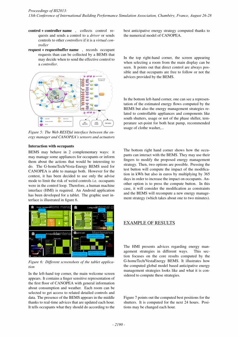
Figure 5: The Web RESTful interface between the en-ergy manager and CANOPEA’s sensors and actuators
Interaction with occupantsBEMS may behave in 2 complementary ways: itmay manage some appliances for occupants or informthem about the actions that would be interesting todo. The G-homeTech/Vesta-Energy BEMS used forCANOPEA is able to manage both. However for thecontest, it has been decided to use only the advisemode to limit the risk of weird controls i.e. occupantswere in the control loop. Therefore, a human machineinterface (HMI) is required. An Android applicationhas been developed for a tablet. The graphic user in-terface is illustrated in figure 6.
real-time advices
direct control
observations
representation of energy fluxes
modification of the energy management strategies
recomputation of energy management strategies
proposition of energy management strategies
Figure 6: Different screenshots of the tablet applica-tion
In the left-hand top corner, the main welcome screenappears. It contains a finger sensitive representation ofthe first floor of CANOPEA with general informationabout consumption and weather. Each room can beselected to get access to related detailed controls anddata. The presence of the BEMS appears in the middlethanks to real-time advices that are updated each hour.It tells occupants what they should do according to the
best anticipative energy strategy computed thanks tothe numerical model of CANOPEA.
In the top right-hand corner, the screen appearingwhen selecting a room from the main display can beseen. It points out that direct control are always pos-sible and that occupants are free to follow or not theadvices provided by the BEMS.
In the bottom left-hand corner, one can see a represen-tation of the estimated energy flows computed by theBEMS but also the energy management strategies re-lated to controllable appliances and components likesouth shutters, usage or not of the phase shifter, tem-perature set-point for both heat pump, recommendedusage of clothe washer,...
The bottom right hand corner shows how the occu-pants can interact with the BEMS. They may use theirfingers to modify the proposed energy managementstrategy. Then, two options are possible. Pressing thetest button will compute the impact of the modifica-tion in kWh but also in euros by multiplying by 365days in order to increase the impact on occupants. An-other option is to press the compute button. In thiscase, it will consider the modification as constraintsand the BEMS will recompute a new energy manage-ment strategy (which takes about one to two minutes).
EXAMPLE OF RESULTS
The HMI presents advices regarding energy man-agement strategies in different ways. This sec-tion focuses on the core results computed by theG-homeTech/VestaEnergy BEMS. It illustrates howthe computed global model based anticipative energymanagement strategies looks like and what it is con-sidered to compute these strategies.
Figure 7 points out the computed best positions for theshutters. It is computed for the next 24 hours. Posi-tions may be changed each hour.
Proceedings of BS2013: 13th Conference of International Building Performance Simulation Association, Chambéry, France, August 26-28
- 2190 -
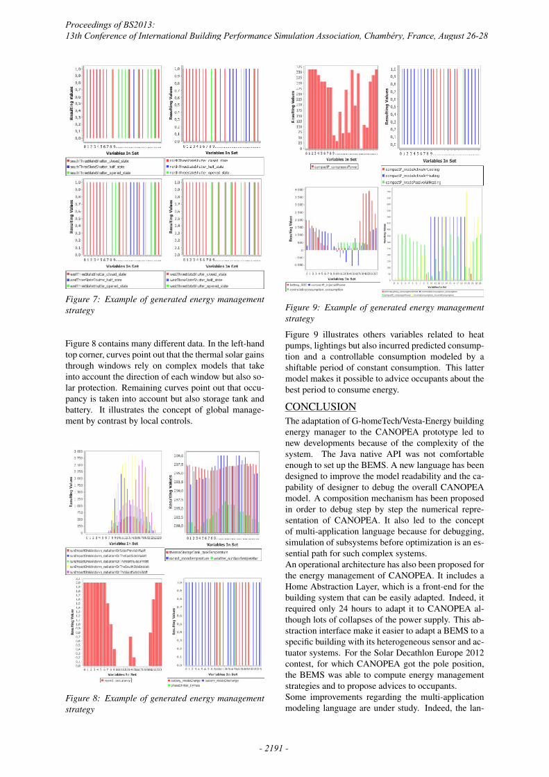
Figure 7: Example of generated energy managementstrategy
Figure 8 contains many different data. In the left-handtop corner, curves point out that the thermal solar gainsthrough windows rely on complex models that takeinto account the direction of each window but also so-lar protection. Remaining curves point out that occu-pancy is taken into account but also storage tank andbattery. It illustrates the concept of global manage-ment by contrast by local controls.
Figure 8: Example of generated energy managementstrategy
Figure 9: Example of generated energy managementstrategy
Figure 9 illustrates others variables related to heatpumps, lightings but also incurred predicted consump-tion and a controllable consumption modeled by ashiftable period of constant consumption. This lattermodel makes it possible to advice occupants about thebest period to consume energy.
CONCLUSIONThe adaptation of G-homeTech/Vesta-Energy buildingenergy manager to the CANOPEA prototype led tonew developments because of the complexity of thesystem. The Java native API was not comfortableenough to set up the BEMS. A new language has beendesigned to improve the model readability and the ca-pability of designer to debug the overall CANOPEAmodel. A composition mechanism has been proposedin order to debug step by step the numerical repre-sentation of CANOPEA. It also led to the conceptof multi-application language because for debugging,simulation of subsystems before optimization is an es-sential path for such complex systems.An operational architecture has also been proposed forthe energy management of CANOPEA. It includes aHome Abstraction Layer, which is a front-end for thebuilding system that can be easily adapted. Indeed, itrequired only 24 hours to adapt it to CANOPEA al-though lots of collapses of the power supply. This ab-straction interface make it easier to adapt a BEMS to aspecific building with its heterogeneous sensor and ac-tuator systems. For the Solar Decathlon Europe 2012contest, for which CANOPEA got the pole position,the BEMS was able to compute energy managementstrategies and to propose advices to occupants.Some improvements regarding the multi-applicationmodeling language are under study. Indeed, the lan-
Proceedings of BS2013: 13th Conference of International Building Performance Simulation Association, Chambéry, France, August 26-28
- 2191 -
guage proposed for CANOPEA is certainly able tohandle simulation and computation of global energymanagement strategies but it is actually not able tohandle parameter estimation problem, which leads tononlinear optimization problems. New principles areunder development: they rely on formal symbolic ma-nipulations of constraints. It will increase the capabil-ity of model transformations.
ACKNOWLEDGEMENTWe would like to thank all the other members of theRhone-Alpes team, that actively participate to the con-struction of the CANOPEA prototype. The BuildingEnergy Management System could not have been in-stalled without the invaluable contribution of all theteam members, especially from the Ecole NationaleSuprieure d’Architecture de Grenoble, the GEII IUT 1of Grenoble and Polytech’Savoie.
REFERENCEShttp://www.sdeurope.org.
http://www.solardecathlon.fr.
Abras, S., Ploix, S., and Pesty, S. 2010. Housing,Housing Costs and Mortgages: Trends, Impact andPrediction, chapter Managing Power in a SmartHome Using Multi-Agent Systems. Number ISBN978-1-60741-813-9 in Housing Issues, Laws andPrograms. Nova Publishers.
Abras, S., Ploix, S., Pesty, S., and Jacomino, M. 2006.Informatics in Control, Automation and RoboticsIII, volume 15 of Lecture Notes in Electrical En-gineering, chapter A multi-agent home automationsystem for power management. Springer BerlinHeidelberg.
Abras, S., Ploix, S., Pesty, S., and Jacomino, M.2007. Artificial intelligence and innovations :from theory to applications, volume 247, chapterA multi-agent design for a home automation sys-tem dedicated to power management, pages 233–242. Springer eBooks collection, isbn 0387741615,9780387741611, edition.
Duffie, J. A. and Beckman, W. A. 2006. Solar engi-neering of thermal processes. John Wiley and Sons,third edition edition.
Duy Ha, L., Ploix, S., Zamaı, E., and Jacomino, M.2006. A home automation system to improve house-hold energy control. In The 12th IFAC SymposiumINCOM2006.
Elmahaiawy, A. M., Elfishawy, N., and El-Dien, M. N.2010. Anticipation the consumed electrical power insmart home using evolutionary algorithms. In MCIT2010 conference.
Eynard, J. 2010. Gestion optimale de l’energiedans un procede multi-source pour le chauffage de
batiments. PhD thesis, l’Universite de PerpignanVia Domitia.
Foggia, G. 2009. Pilotage Optimal de Systeme Multi-sources pour le Batiment. PhD thesis, Grenoble In-stitute of Technology (INPG).
Ha, L. D., Joumaa, H., Ploix, S., and Jacomino, M.2012. An optimal approach for electrical manage-ment problem in dwelings. Energy and Buildings,45:1–14.
Ha, L. D., Le Minh, H., and Ploix, S. 2008a. An ap-proach for home load energy management problemin uncertain context. In IEEE International Con-ference on Industrial Engineering and EngineeringManagement, Singapor.
Ha, L. D., Ploix, S., Jacomino, M., and Le Minh, H.2010. Energy Management, chapter A mixed inte-ger programming formulation of the home energymanagement problem. ISBN 978-953-307-065-0.INTECH.
Ha, L. D., Ploix, S., Wurtz, F., Perichon, P., andMerten, J. 2009. Energy management system fora photovoltaic grid-connected building. In 24th EUPVSEC and 4th World Conference on PhotovoltaicEnergy Conversion, Hamburg, Germany.
Ha, L. D., Ploix, S., Zamaı, E., and Jacomino, M.2006. Tabu search for the optimization of house-hold energy consumption. In The 2006 IEEE Inter-national Conference on Information Reuse and In-tergration IEEE IRI 2006, Waikoloa Hawaii, USA.
Ha, L. D., Ploix, S., Zamaı, E., and Jacomino,M. 2008b. Realtimes dynamic optimization fordemand-side load management. International Jour-nal of Management Science and Engineering Man-agement, 3(4).
Henze, G. P. and Dodier, R. H. 2003. Adaptive optimalcontrol of a grid-independent photovoltaic system.Transactions of the ASME, 125:34–42.
Negenborn, R. R. 2007. Multi-agent model predictivecontrol with applications to power networks. PhDthesis, Technische Universiteit Delft, Delft, Nether-lands.
Palensky, P. and Posta, R. 1997. Demand side manage-ment in private home using lonworks. In Proceed-ings of the IEEE International Workshop on FactoryCommunication Systems.
Penya, Y. 2003. Last generation applied artificial intel-ligence for energy management in building automa-tion. In The 5th International Conference on Field-bus Systems and their Applications, Aveiro, Portu-gal.
Proceedings of BS2013: 13th Conference of International Building Performance Simulation Association, Chambéry, France, August 26-28
- 2192 -

Ploix, S., Duy Long, H., Abras, S., Jacomino, M.,Wurtz, D., and Bacha, S. 2010. patent us/eu61/326,542: Environment and method for manag-ing services in a living place.
REACTIVHOME. https://reactivhome.rd.francetelecom.com.
Riffoneau, Y. 2010. Gestion des flux energetiques dansun systeme photovoltaıque avec stockage connecteau reseau. PhD thesis, Grenoble Institute of Tech-nology (INPG).
Wacks, K. 1993. The impact of home automation onpower electronics. In Applied Power ElectronicsConference and Exposition, pages 3–9.
Warkozek, G., Jacomino, M., Ploix, S., and Wurtz, F.2009. Generic formulation of optimization prob-lems for energy management: solving difficulties,practical and mathematical analysis. In Proceedingsof the 8th International Symposium on Electric andMagnetic Fields (EMF2009), Mondovi, Italy.
Proceedings of BS2013: 13th Conference of International Building Performance Simulation Association, Chambéry, France, August 26-28
- 2193 -