Embed Size (px)
Citation preview
A GRAPHICAL APPROACH TO TESTING
REAL-TIME EMBEDDED DEVICES
A Thesis
presented to
the Faculty of California Polytechnic State University,
San Luis Obispo
In Partial Fulfillment
of the Requirements for the Degree
Master of Science in Computer Science
by
Steven Michael Day
June 2009

ii
© 2009
Steven Michael Day
ALL RIGHTS RESERVED

iii
COMMITTEE MEMBERSHIP
TITLE: A Graphical Approach to Testing Real-Time
Embedded Devices
AUTHOR: Steven Michael Day
DATE SUBMITTED: June 2009
COMMITTEE CHAIR: Dr. Tim Kearns
COMMITTEE MEMBER: Dr. Franz Kurfess
COMMITTEE MEMBER: Dr. Clark Turner
iv
ABSTRACT
A Graphical Approach to Testing Real-Time Embedded Devices
by
Steven Michael Day
Software Testing is both a vital and expensive part of the software
development lifecycle. Improving the testing process has the potential for large
returns. Current testing methodologies used to test real-time embedded devices
are examined and the weaknesses in them are exposed. This leads to the
introduction of a new graphical testing methodology based on flowcharts. The
new approach is both a visual test creation program and an automated execution
engine that together frame a new way of testing. The new methodology
incorporates flow-based diagrams, visual layouts, and simple execution rules to
improve upon traditional testing approaches. The new methodology is evaluated
against other methodologies and is shown to provide significant improvements in
the area of software testing.
v
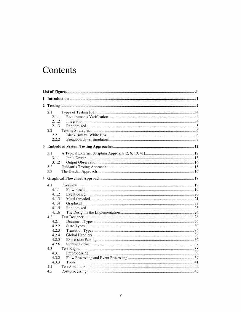
Contents
List of Figures ............................................................................................................................... vii
1 Introduction ............................................................................................................................... 1
2 Testing ........................................................................................................................................ 2
2.1 Types of Testing [6] ...................................................................................................... 4 2.1.1 Requirements Verification........................................................................................ 4 2.1.2 Integration ................................................................................................................ 4 2.1.3 Randomized.............................................................................................................. 5
2.2 Testing Strategies .......................................................................................................... 6 2.2.1 Black Box vs. White Box ......................................................................................... 6 2.2.2 Breadboards vs. Emulators ....................................................................................... 9
3 Embedded System Testing Approaches................................................................................. 12
3.1 A Typical External Scripting Approach [2, 6, 10, 41]................................................. 12 3.1.1 Input Driver ............................................................................................................ 13 3.1.2 Output Observation ................................................................................................ 14
3.2 Guidant’s Testing Approach ....................................................................................... 15 3.3 The Dasdan Approach................................................................................................. 16
4 Graphical Flowchart Approach ............................................................................................. 18
4.1 Overview..................................................................................................................... 19 4.1.1 Flow-based ............................................................................................................. 19 4.1.2 Event-based ............................................................................................................ 20 4.1.3 Multi-threaded ........................................................................................................ 21 4.1.4 Graphical ................................................................................................................ 22 4.1.5 Randomized............................................................................................................ 23 4.1.6 The Design is the Implementation.......................................................................... 24
4.2 Test Designer .............................................................................................................. 26 4.2.1 Document Types..................................................................................................... 26 4.2.2 State Types ............................................................................................................. 30 4.2.3 Transition Types..................................................................................................... 34 4.2.4 Global Handlers...................................................................................................... 36 4.2.5 Expression Parsing ................................................................................................. 36 4.2.6 Storage Format ....................................................................................................... 37
4.3 Test Engine.................................................................................................................. 38 4.3.1 Preprocessing.......................................................................................................... 39 4.3.2 Flow Processing and Event Processing .................................................................. 39 4.3.3 Tools....................................................................................................................... 41
4.4 Test Simulator ............................................................................................................. 44 4.5 Post-processing ........................................................................................................... 45

vi
5 Evaluation ................................................................................................................................ 47
5.1 Strengths...................................................................................................................... 48 5.2 Weaknesses ................................................................................................................. 52 5.3 Speed of Implementation............................................................................................. 56
6 Future Work ............................................................................................................................ 58
7 Concluding Remarks............................................................................................................... 60
Bibliography ................................................................................................................................. 62
vii
List of Figures
4.1 GiFT System Overview .............................................................................19
4.2 Event-based processing. The execution will proceed from the initial
state to the success state when the event Sig.Charging_Completed is
processed....................................................................................................20
4.3 Multiple flows simulate a multi-threaded application ...............................21
4.4 The Test Designer ......................................................................................26
4.5 The Document Hierarchy...........................................................................27
4.6 Ordinary state.............................................................................................31
4.7 Decision state .............................................................................................31
4.8 Success state...............................................................................................32
4.9 Failure state................................................................................................33
4.10 Final State ..................................................................................................33
4.11 Macro invocation state...............................................................................34
4.12 Testcase reference state..............................................................................34
4.13 Custom expression editor...........................................................................37
5.1 GiFT vs. Typical Approach Comparison...................................................57
1
Chapter 1
Introduction
As a society, we are becoming increasingly dependent on embedded devices
to perform safety-critical operations. These embedded devices may be found in
such applications as automobiles, avionics, nuclear power plants, and medical
devices. Due to their critical nature, we place an utmost importance on the testing
of these products. While being completely necessary, the large effort spent on
testing is quite expensive [6]. If the efficiency of the testing activity can be
improved while maintaining or improving its effectiveness, there is potential for
enormous gains.
In this thesis, various testing activities will be examined with an emphasis on
the common approaches used by embedded systems companies. After the
overview, an entirely new paradigm for testing embedded systems will be
detailed. The deficiencies of the common approaches will be identified and
analyzed in the context of the new paradigm. The new paradigm will be evaluated
against the other approaches to illustrate its strengths and weaknesses. In the end,
it will be shown that this new paradigm offers significant improvements over the
other approaches while preserving the effectiveness of the testing activity.
2
Chapter 2
Testing
Software testing is one of the most expensive phases of the software
development lifecycle. The cost is particularly high when it concerns embedded
systems [14]. Included in the cost breakdown is the manpower to design, execute,
and verify the tests as well as the delay in time-to-market for a software product.
Despite the high cost of software testing, it is performed for two reasons:
Regulation
Many embedded systems are safety-critical in nature. For these applications,
there is typically a governing body that regulates the testing and manufacture of
the products. For example, medical device companies are regulated by the Food
and Drug Administration (FDA). The FDA has guidelines and policies that drive
much of the software development process within a medical device company. Part
of these guidelines include the implementation and review of software testing.
Tests must be designed to cover each of the software requirements and then they
must be reviewed, implemented, executed, and the results verified [42, 43].
3
Without an adequate software testing strategy, the FDA could revoke the
ability for a medical device company to do business. Recent history with the
medical device manufacturer Guidant has shown that the FDA will take such
drastic measures when they feel a company is not performing to standards [3].
Oversight is a major motivation for embedded systems companies to maintain a
thorough software testing strategy.
Product Quality
Aside from the threat of having business halted by a governing body, there is
a strong motivating factor in the free marketplace to produce a quality product. In
the free market, it is in the company’s best interest to produce items at a higher
quality and lower cost than its competitors. Software testing plays a major role
towards this goal.
Recently, there have been product recalls among two major embedded
systems companies [1, 31]. Product recalls can prove disastrous for increasing
business and growth. One of the ways to reduce such recalls is to release a
product free of major defects. The traditional way of reducing major defects in
software products is through software testing [29].
4
2.1 Types of Testing [6]
Software testing is a broad topic. There are many different types of software
testing that occur at various stages of the software development lifecycle. The
following is an overview of the various types of testing addressed in this paper:
2.1.1 Requirements Verification
Requirements verification is a special type of testing activity. Requirements
verification can be summed up by the phrase, “Did we build what we said we
were going to build?”
Requirements verification is an activity that tests the product against the
product’s requirements to ensure they match. There are many different
approaches that may be used to this end, but the activity remains the same – to
verify that the product behaves exactly as described in the requirements [11].
2.1.2 Integration
Integration testing focuses on testing a unit while running within a system as
well as the effects of the system on a particular unit. Integration testing is a very
complex, yet important activity [6]. There are many potential issues that could be
identified by integration testing but would never be uncovered by unit testing
alone. An example of one such issue would be a conversion method. Suppose
method CalculateMPH(float time, float distanceInFeet) works well in a unit test.
Suppose method ConvertToMiles(float distInFeet) also works well in a unit test.
The interaction between the two is what is tested with integration testing. Suppose
this call is made: CalculateMPH(60.0,ConvertToMiles(5280.0)). The problem
5
here is that CalculateMPH is expecting an input in feet, but receives an input in
miles. This problem isn’t apparent until the interaction between the two is tested.
Integration testing is very important, but it is sometimes difficult to identify
all of the interactions that are important to test [37]. This makes it difficult for
anyone except an entire system expert to design such tests. The expert must
understand the implementation of the system and the impact different units within
the system may have on each other.
2.1.3 Randomized
The theory behind randomized testing is that even an expert test designer may
miss designing a test for an important interaction. To help eliminate this gap, a
randomized test may be constructed such that it varies the test execution each
time it is run. The randomization may vary the setup of the environment before
the test begins, vary different inputs, and vary different code branches of
execution. As the test runs, the results are compared with expected results for the
given input values and setup environment. If the actual results don’t match
expected results, the test is flagged as a failure.
Pseudo-randomness can also be introduced to aid in the targeting of specific,
known trouble areas within the code. For example, many test failures occur at the
edges of a boundary because of erroneous boundary conditions [19, 21]. In this
regard, the pseudo-randomness can be distributed in such a way that the boundary
conditions are tested more often that the middle of a distribution.
6
One important practical consideration for randomized testing involves storing
the generated values that were used in each test. Without this information,
repeating the condition for debugging would prove to be quite difficult.
2.2 Testing Strategies
While defining the fundamental testing approach for an application, there are
high-level testing strategies that must be considered. Here are two of the foremost
strategic decisions that must be given consideration:
2.2.1 Black Box vs. White Box
Black box and white box are two different approaches to software testing.
Black box is a term used to describe testing without any knowledge of the
internals of the system under test. White box, also sometimes referred to as clear
box, is a term used to describe testing that makes use of internal knowledge about
a system’s construction [32].
Black box testing is best described as testing a system by only giving it inputs
and observing its outputs. Nothing about the system can be inspected aside from
the outputs and nothing about the system can be altered aside from the inputs.
This type of testing is usually the least complicated, but it also makes for difficult
problem-solving when an error condition occurs.
Black box testing is beneficial because of its simplicity. This testing approach
utilizes the same interface to the system as will be used post-production. There is
no additional instrumentation, apparatus, or external device development and cost
associated with black box testing. The testing harness is easily designed because it
7
utilizes a very stable, well-known interface instead of a custom, testing-only
interface.
Although the simplicity of black box testing can be a benefit, it can also be a
detriment. Because very little instrumentation is available with black box testing,
it is difficult to diagnose errors. Another drawback of black box testing is the
inability to thoroughly set up a testing scenario. For instance, if a timer rollover is
to be tested, it would be beneficial to set the timer to a point right before it expires
before starting the test. Unfortunately, black box testing does not allow for such
modifications and requires the test to wait for the timer to count until rollover
time. This has the potential of adding unnecessary time delays to the test.
White box testing is best described as testing a system with a clear view of the
internal structure of the system. With white box testing, the inputs and outputs
may be used for testing but there is a wide array of other options. In some cases,
the inputs and outputs may be completely ignored because instrumentation may
monitor and alter the internals of the system to set up and assess the
successfulness of a test [26].
White box testing is beneficial because of its flexibility and ability to monitor
specific conditions that cannot be isolated with black box testing. With black box
testing, a test may have to wait for a timer to expire or some long series of events
to occur before executing the test. With white box testing, the internals of the
system may be modified to simulate the situation without the added time of
waiting for the condition to occur naturally. White box testing also has the ability
to be much more specific in the observations it makes. At a black box testing
8
perspective, the correct output causes success, but with white box testing we can
ensure that the correct values are set internally in many places and have a much
clearer picture of the state of the entire system at any given point in time. This
helps a great deal with the debugging of a failed test [12].
There are also disadvantages to white box testing. While the ability to monitor
the software is beneficial, it is also more expensive and time-consuming to
develop a testing harness to allow such invasive behavior. In addition, white box
testing may give too much control and the test may stop watching the state of the
system before the output is really achieved. With black box testing, it is necessary
to view the output after it comes down the entire pipeline; with white box testing,
we may assume our test passes because the result coming out of a single function
is correct, but it may be the case that the correct result is erroneously modified on
its way out of the pipeline. Another disadvantage is that errors observed in a test
may be an actual error in the system, but it is possible that it may be an artifact of
the testing apparatus, especially for real-time systems. Errors in testing apparatus
are common in real-time system testing due to the tight timing constraints placed
on the system. If the test apparatus and the system under test become out of sync,
false-positive errors will likely occur that cause an error result but do not
necessarily indicate a fault with the device under test. These tight timing
constraints are only a problem when using white box testing due to the need to
keep the test apparatus in sync with the device under test for every operation it
performs.
9
There are distinct advantages and disadvantages to both black box and white
box testing. To get the most benefit out of testing, the approach may be a blend of
both types. The trade-offs of both white and black box testing must be considered
thoroughly before deciding on which approach to use for each type of testing
scenario.
2.2.2 Breadboards vs. Emulators
Embedded systems are composed of both hardware and software [30]. To
execute the software for an embedded system, the hardware must be modeled.
There are two main approaches for modeling an embedded system’s hardware for
testing purposes. The first approach is to build the actual hardware on a test
bench. This is called breadboarding. The second approach is to build a software
emulator that emulates the entire device [5].
Breadboarding is the equivalent of building the actual embedded device
hardware, but without the cost of doing so for the actual application. For instance,
if an embedded device must be the size of a deck of playing cards and encased in
a titanium shell, there is significant cost in manufacturing on such a small scale
with expensive materials. If, however, the hardware was laid out onto a one foot
by two foot electronics board, the circuitry remains the same but there is no need
for the cost to manufacture on a small scale. In addition, any expensive casing
materials, supports, etc. are removed from the equation. The result is a hardware
replica of the actual device to be built. This hardware replica may also sometimes
include additional instrumentation that will not be included in the final hardware
manufacturing build [24].
10
The advantages of breadboarding are many. The main advantage to
breadboarding is that hardware and software interactions can be tested under
actual hardware conditions. It has been recognized that the boundary between
hardware and software is poorly understood [38]. By using a breadboard and
testing both the hardware and software systems together as a whole, the boundary
between the systems is thoroughly tested as well. In addition, the hardware and
software platform runs at real-time, just like the final embedded device will
eventually do. Due to these factors, it is more likely that problems pertaining to
hardware and software interactions will be recognized on a hardware replica.
Breadboarding includes some disadvantages – mainly related to cost. If there
are many materials involved and a large number of testing stations to be built, the
cost may be high. Any changes to the hardware layout are usually expensive to
change because it may involve creating a new breadboard layout and replacing or
updating all of the existing breadboards. Some of these costs may be avoided with
on-board swappable hardware chips but there still exists a cost, especially if the
number of breadboards is large.
Another approach to the testing of embedded systems is to create a software
emulator that emulates the hardware part of the system. This approach is
exhibited with simple emulators, such as the emulators that run on PCs to emulate
popular videogame consoles. The idea here is the same, except that the emulator
is emulating custom, real-time hardware instead of a well-known and recognized
platform.
11
The advantages of emulators include the cost effectiveness when there are
many test benches to be built. The cost to build an emulator is static, and once
built it can be reproduced any number of times. This is contrasted with the cost to
build breadboards. Each deployment of a breadboard requires additional cost. In
addition, changes and updates to the emulator are also easily distributed, unlike an
update to a breadboard.
While emulators may be less expensive than breadboards over a large number
of installations, there is still a high development cost. Not only is the initial
development expensive, but there also exists a need to verify accuracy that the
emulator is properly emulating the hardware that will be built [17]. With
breadboards, the hardware is virtually identical, except for scale and additional
diagnostic equipment. With an emulator, there is a painstaking verification effort
that must be completed on the emulator itself before it can be used for its intent to
verify software. Because the emulator is also software, there may be hardware
issues lurking that remain undiscovered. Likewise, it is necessary to ensure that
the emulator runs at real-time so that it doesn’t obscure any problems with real-
time actions that may be present.
Both breadboarding and emulating hardware are viable options for testing a
real-time, embedded system. There are trade-offs with each approach that must be
considered before implementing a testing strategy.
12
Chapter 3
Embedded System Testing Approaches
While evaluating any new paradigm, it is useful to survey existing paradigms
for comparison. The new paradigm presented in this paper applies specifically to
the testing of embedded devices from an external standpoint on a physical
hardware platform. Because of this focus, the approaches used for comparison
will be limited in the same fashion.
This section will describe a typical external scripting testing approach for
embedded systems, the verification testing paradigm in use at one embedded
systems company, and a paradigm proposed in an academic paper.
3.1 A Typical External Scripting Approach [2, 6, 10,
41]
Given the limitations of testing a non-emulated embedded platform from an
external viewpoint, there are few limited choices in the approach. The general
strategy for testing an embedded system using a breadboard is a simple input-
output method. The embedded device is set into some starting state, inputs are
driven into the device, and the state of the device is observed. To accomplish this
13
approach, there must be a method for driving inputs and a method for observing
the state of the device.
3.1.1 Input Driver
Regardless of white or black box testing approach, the decision to use a
breadboard for testing causes a need to generate inputs that drive the system. One
possible implementation of a test driver is a simple C++ program. This program is
usually started with a skeleton to set the breadboard into a known state, trigger the
observation of outputs, perform testing steps, trigger the saving of the outputs to a
file, and stop any activity occurring on the device by setting it into a resting state.
To determine test success or failure, the output file must be analyzed and
compared to expected output.
The workflow for a verification test engineer begins with the test template that
outlines the initialization and cleanup needed for each test. The verification
engineer then adds routines to the template, utilizing any pre-defined custom
library calls. The last part of the test design includes laying out the criteria against
which the results will be measured to determine success or failure of the test. The
engineer then attempts to run the test on a test bench. At the completion of the
test, there are log files and outputs from the device that are measured before a
success or failure result is reported. If the test does not pass successfully, it is
reexamined to determine if there is an error with the test code or if the test has
uncovered an actual error with the device under test.
14
3.1.2 Output Observation
To observe the output of the breadboard during a test, there are a number of
necessary tools. These tools are mostly windows into the internals of the system
that allow viewing the state of the system. These tools include the logic analyzer,
digital interface, and code coverage recorder.
The logic analyzer is a common tool in the embedded system industry [17]. It
is a standard tool that watches values in the hardware and triggers the recording of
updates to a file. The recording is customizable such that only the values of
interest may be recorded. The recording may be set up to record immediately or to
record only after a certain event occurs. The resulting file is called a trace file. It
is a chronological record of the events that happened within the area of firmware
that was being monitored.
The digital interface allows direct viewing of data on the breadboard. The
digital interface is similar to the logic analyzer in that it watches the firmware.
The difference is that instead of logging actions to a file, the digital interface
reports specific events back to a piece of monitoring software. This software is
usually a C++ program that is running to test the device. When the events are
reported back to the software, the software may make decisions based upon the
occurrence of an event.
The code coverage recorder has its own interface to the device that triggers
the recording of information into a file when certain areas of the code under test
are executed. After running all tests, the aggregation of all of these files may be
analyzed to ensure that every piece of the code under test was executed.
15
3.2 Guidant’s Testing Approach
In a Doctoral Thesis titled, “A Requirement Verification Framework for Real-
time Embedded Systems” [45], author Feng Zhu details the methodology used for
verification of embedded device software at a medical device company called
Guidant. His thesis covers their previous method of testing as well as the
improvement he made to the process by introducing standard templates.
At Guidant Corporation, verification testing was done by writing C++ code.
Each test case was developed as a separate C++ program and executed
independently of all other test cases. The C++ program contained all of the
necessary startup, test setup, and cleanup procedures. In addition, the main part of
the test contained implementation that is specific to testing the given requirement.
In his thesis [45], Feng Zhu successfully transforms the verification effort
from unnecessary repetition into heavy re-use. Feng Zhu identified patterns
among the entire suite of tests used at Guidant. From his pattern identification, he
was able to produce eight templates that cover approximately 95% of all tests that
need to be written. Armed with the library of templates, the test engineer may
more quickly develop a suite of tests. The engineer is no longer required to re-
implement functionality that is common to many tests of a single type.
Aside from the improvement made to the process by adding standard
templates, the testing methodology still requires re-implementation of the setup
and cleanup code within each test, the single test per executable, and the low-level
knowledge of the test system required by the test engineer to implement a test.
16
This approach offers opportunities for improvement with the new methodology
that will be examined later.
3.3 The Dasdan Approach
In the paper, “An Interactive Validation Methodology for Embedded
Systems” [13], the authors describe an approach for ensuring that timing
constraints are met by the system. Their approach heavily utilizes graphs and
simulation to determine the outcome of the test. They propose moving testing to
higher levels of abstraction and introducing it early in the design cycle.
The approach proposed by the authors of the paper begins by abstracting the
testing away from the actual implementation. The testing process relies on graphs
and simulation to estimate best-case and worst-case timing scenarios. Their
approach is to run the tests very early in the design cycle and revisit the design if
the test results are unsatisfactory.
While this approach makes a very good point to run tests early in the design
cycle, it has the pitfall that it relies mainly upon simulation to determine results of
time-based tests. As stated previously in this paper, simulation has both strengths
and weaknesses. One of the weaknesses of simulation is the inability to fully
capture hardware and software interactions that may negatively impact timing
constraints. It is important to take actual measurements from an embedded device
to ensure the timing constraints are met. Due to the heavy use of simulation
emphasized by the authors of “An Interactive Validation Methodology for
Embedded Systems,” it is a tool that would possibly be considered during design

17
time, but it is not an approach that would be considered for the final device
firmware verification of a safety-critical embedded application.
18
Chapter 4
Graphical Flowchart Approach
To address the pitfalls of the various testing approaches, a new paradigm has
been developed. It is called GiFT: Graphical interface Flowchart Tool.
The approaches detailed in the previous section and GiFT share many
similarities. In fact, the testing apparatus and overall testing strategy need not
change when evaluating GiFT against the typical testing approach. The real focus
of the new paradigm is on the way the end-user of the test system develops test
cases, executes the tests, and interprets the results.
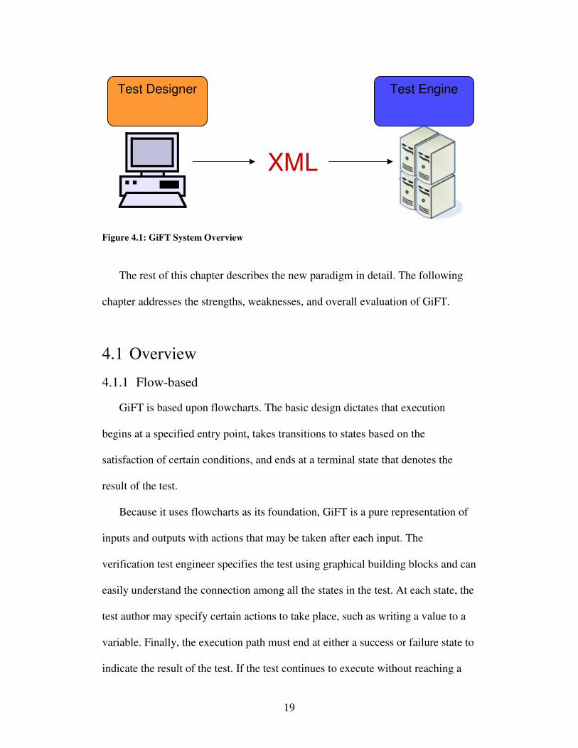
GiFT is a test design and execution tool comprised of a flowchart-based
graphical interface and an event-based processing engine. Tests are designed in
the test designer application on a user’s workstation before being sent to the test
engine for execution. The test designs are immediately executable without the
need for any additional implementation. The test engine executes the test and
determines the result.
19
Figure 4.1: GiFT System Overview
The rest of this chapter describes the new paradigm in detail. The following
chapter addresses the strengths, weaknesses, and overall evaluation of GiFT.
4.1 Overview
4.1.1 Flow-based
GiFT is based upon flowcharts. The basic design dictates that execution
begins at a specified entry point, takes transitions to states based on the
satisfaction of certain conditions, and ends at a terminal state that denotes the
result of the test.
Because it uses flowcharts as its foundation, GiFT is a pure representation of
inputs and outputs with actions that may be taken after each input. The
verification test engineer specifies the test using graphical building blocks and can
easily understand the connection among all the states in the test. At each state, the
test author may specify certain actions to take place, such as writing a value to a
variable. Finally, the execution path must end at either a success or failure state to
indicate the result of the test. If the test continues to execute without reaching a
XML
Test Engine Test Designer
20
success or failure state, a test case timer will hit its limit and stop the test. In the
case of the test case timer, the test author may specify that either success or failure
is reported when the timer expires.
4.1.2 Event-based
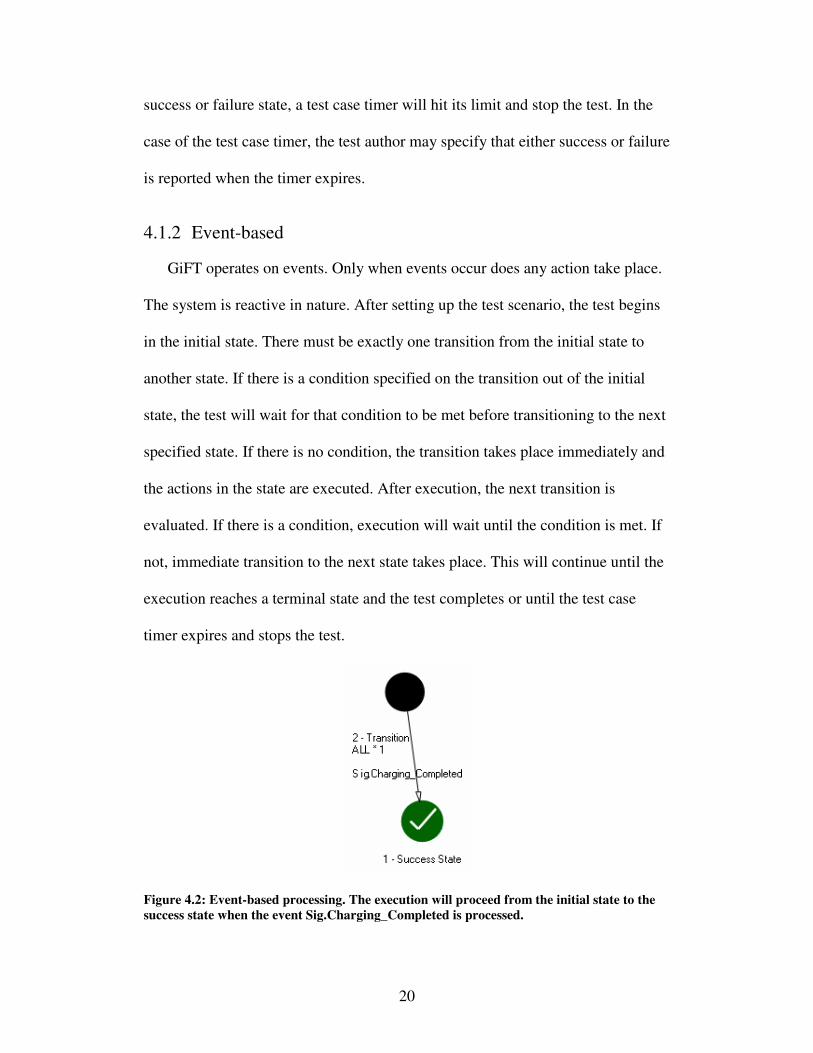
GiFT operates on events. Only when events occur does any action take place.
The system is reactive in nature. After setting up the test scenario, the test begins
in the initial state. There must be exactly one transition from the initial state to
another state. If there is a condition specified on the transition out of the initial
state, the test will wait for that condition to be met before transitioning to the next
specified state. If there is no condition, the transition takes place immediately and
the actions in the state are executed. After execution, the next transition is
evaluated. If there is a condition, execution will wait until the condition is met. If
not, immediate transition to the next state takes place. This will continue until the
execution reaches a terminal state and the test completes or until the test case
timer expires and stops the test.
Figure 4.2: Event-based processing. The execution will proceed from the initial state to the
success state when the event Sig.Charging_Completed is processed.
21
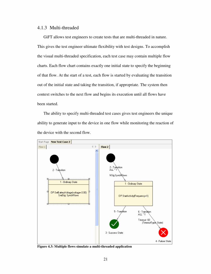
4.1.3 Multi-threaded
GiFT allows test engineers to create tests that are multi-threaded in nature.
This gives the test engineer ultimate flexibility with test designs. To accomplish
the visual multi-threaded specification, each test case may contain multiple flow
charts. Each flow chart contains exactly one initial state to specify the beginning
of that flow. At the start of a test, each flow is started by evaluating the transition
out of the initial state and taking the transition, if appropriate. The system then
context switches to the next flow and begins its execution until all flows have
been started.
The ability to specify multi-threaded test cases gives test engineers the unique
ability to generate input to the device in one flow while monitoring the reaction of
the device with the second flow.
Figure 4.3: Multiple flows simulate a multi-threaded application
22
There is also a means of communication among flows such that
synchronization among flows may be attained. This is accomplished with a
Named Signal. Named Signals are messages that are broadcast to each flow. To
achieve synchronization, each flow can be in the initial state with a transition out
that is waiting for the Named Signal to occur. To begin the test, the driving flow
will issue the Named Signal. Upon receipt of the Named Signal by each flow,
flow execution will begin. The same ability may be used at any point during the
flow; its use is not limited to the beginning.
4.1.4 Graphical
One of the key elements of GiFT is that it is graphical in nature. The test
engineer creates tests by using a graphical editor. The editor allows the
specification of varying types of states and transitions. It also allows the editing of
actions that occur within each state and the editing of conditions that may be
present for a given transition out of a state. There is also a graphical editor for
inputting expressions in a proprietary expression language.
In addition to the test design application being graphical in nature, there are
other supplemental tools that are also graphical. After a test has run on the test
station, the resulting log files may be used to graphically illustrate the path that
was taken through the test flow. Another graphical tool uses an aggregation of
multiple test run logs to show test coverage over a period of time. This activity
ensures that each branch within the test has been taken at least once.
The graphical nature of GiFT is a great benefit to people involved in the
testing process that do not have a background in software [20]. Each time a test is
23
designed and implemented for a safety-critical application, the domain’s
governing body usually mandates a review of the test [42, 43]. In each review,
there should be representation from the Verification group, the Software group,
the Systems group, and other organizations that are not solely based in software.
For these groups, a test review is much more meaningful when they may inspect a
visual representation of the test design instead of trying to decipher source code
that is somewhat foreign to them. The foundation of GiFT’s test designs is a
flowchart, and because flowcharts are conceptually simple [20, 37], test designs in
GiFT are easily comprehended.
4.1.5 Randomized
A core feature of the GiFT system is the ability to specify tests that execute in
a pseudo-random nature. This feature is used mainly by the integration testing
activity, but it is also useful for other testing types.
Randomization in GiFT works by allowing the test engineer to specify many
various actions, decisions, and settings with some randomness to them.
Randomization may be used in actions for setting values for variables. The
random function allows setting a value that is within the valid range, a value equal
to the max of the range, or a value equal to the min of the range. Decisions may
also use randomness to guide a test down different pathways each time it is run.
The action state may set a variable to a random value. The transitions out of that
state may compare to the variable’s value and the transition will be taken if the
condition is met. For each execution, the actual path taken may be different.
Initial test case settings may also utilize the randomization feature to set the
24
embedded device into a random state before beginning a test. This is useful for
verifying that an algorithm can identify behavior regardless of the initial state of
the device.
4.1.6 The Design is the Implementation
One of the key features of GiFT is that the test design is the implementation.
Traditionally, the test scenario is studied before designing a test plan. From the
test plan, an actual test implementation is created. With GiFT, the test plan and
test implementation are one and the same.
To achieve the goal of combining test design with test implementation, GiFT
uses a proprietary file format. The output of the graphical test designer is a format
that can be input and understood by the test engine. It is executable without any
further intervention from the test engineer. This format is similar to a serialized
object class that is then de-serialized by the test engine. The core data layer is
shared between the test designer and test engine so that this serialization
technique may be used.
By making the design and implementation one and the same, there is a great
reduction in effort expended by the test engineer. There is also a reduction in
flexibility. While this may seem like a negative effect, it is actually quite positive.
With the increased rigidity, test engineers must conform to using the tools
available to them and this keeps their designs within the bounds of a properly
formatted test. Unlike C++, they no longer have the freedom to perform actions
outside of what is designated for them. This increases uniformity across tests. The
increased rigidity also means that all of the low-level interface with the test
25
station and the device are implemented only once in the test engine. Any
deficiency discovered by a test engineer may be resolved once in the test engine
with widespread benefit for all tests that are executed by the test engine in the
future.
An additional benefit of having the design and the implementation be one and
the same is that there is a guarantee that the design will always match the
implementation. This is a rule that is not automatically enforced when using C++
as a test implementation. With a C++ implementation, minor adjustments to the
test implementation may not always be reflected in the design since the design
stage is generally finished when the implementation stage begins.
26
4.2 Test Designer
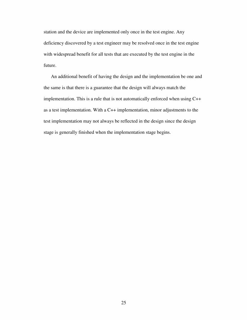
The test designer is the application used by testing engineers to create visual
tests. It is meant to be run directly on a user’s desktop computer and is
independent of the execution of the test. The following sections describe the test
designer. Once the test design is complete, the test is moved to the test engine for
execution.
Figure 4.4: The Test Designer
4.2.1 Document Types
To implement the test system to be flexible enough for test engineers to fully
express their test designs, GiFT has seven document types that it recognizes. The
document types are Testcase, Macro, Testsuite, Configuration, Condition,
Constant, and Formula. The document types all interact with each other to create
a full test.
27
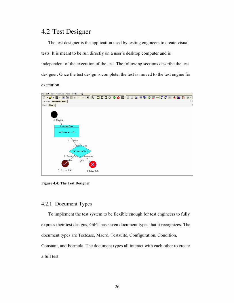
Figure 4.5: The Document Hierarchy
Testcase
A Testcase is the main document. It is one of two executable document types.
The Testcase may be standalone or it may include references to various
components that it can import. A Testcase may include references to all of the
other document types except a Testsuite. The Testcase is comprised of many
components itself. These components include states, transitions, configurations,
global handlers, etc. The Testcase must include at least one flow, one initial state
per flow, and one terminal state per flow with a path between the initial state and
terminal state. Optionally, the Testcase may include multiple flows to implement
a multi-threaded Testcase.
Testcase
Macro
Testsuite
Configuration
Condition
Formula
Named Signal
Constant

28
Macro
A Macro is very similar to a Testcase. The main difference is that a Macro is
never run from within its own context; a Macro must always be invoked from
within a Testcase or another Macro. As such, a Macro requires the use of a final
state to indicate return of control to the parent when it is reached. A Macro also
lacks the ability to set a configuration before execution since it is always invoked
from an already executing state. The third large difference is that a Macro may
only contain one single test flow. By specifying a piece of a Testcase as a Macro,
it is easy to gain re-use out of a single common implementation; the Macro may
be referenced by many different Testcases or other Macros.
Testsuite
A Testsuite is a collection of Testcases. The Testsuite is the other executable
document type aside from a single Testcase. The Testsuite has properties of its
own, including the number of times each Testcase should execute, the seed to
feed into the randomization function, the configuration to set the system under
test into before execution, and a set of actions that may be performed before, in
between, and at the end of the set of Testcase executions.
Configuration
The Configuration document is similar to a settings file. The file is a large
collection of parameters that may be programmed to the embedded system at any
29
time before, during, or after a test. After designing the specific Configuration, it
may be used within a Testcase or Testsuite.
Condition
The Condition document is a way to express a condition for a transition or a
global handler. By creating a document to hold the Condition information, the
same condition may be used in multiple places across many different documents
without repeating work. The Condition document is used within Testcases and
Macros.
Named Signal
The Named Signal is an object that is used for communication among flows.
The Named Signal does not have any properties associated with it, but its role is
very important. When there is a need for synchronization or message passing
between flows, the Named Signal is the means to accomplish the task. The
Named Signal is a document type so that more than one Named Signal may be
created and used among flows. The Named Signal may be referenced by both
Testcases and Macros.
Constant
The Constant document is similar to the Condition document because of its
purpose: to reduce the amount of re-work within test designs. By defining the
Constant once in a Constant document, the same Constant may be referenced in
30
many test designs. If there is ever a need to change that Constant, the change need
be made in only one central location. The Constant document may be used within
a Testcase, Macro, Condition, or Configuration.
Formula
The last document type is a Formula. A Formula is a way to capture an
expression that takes inputs to provide an output. Instead of having many different
implementations of the same Formula in many different locations, the Formula is
defined once and referenced in many places. If a change to the Formula is
necessary, it is a single, central change instead of updating all the items that
reference it. A Formula may be used within any expression.
4.2.2 State Types
There are many different states that may be used within a test flow. Each state
type has its own properties and behavior. The state types are: Ordinary, Decision,
Success, Failure, Final, Macro Invocation, and Testcase Reference.
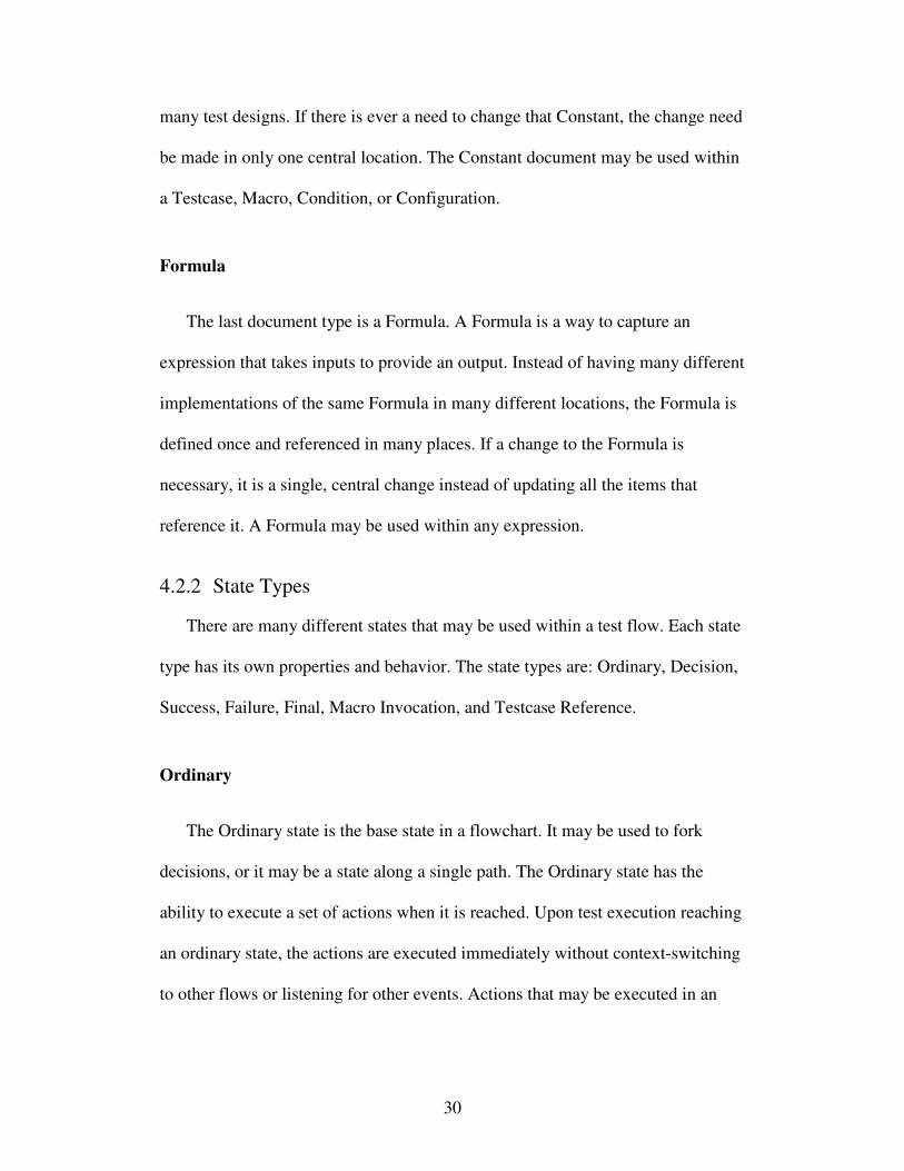
Ordinary
The Ordinary state is the base state in a flowchart. It may be used to fork
decisions, or it may be a state along a single path. The Ordinary state has the
ability to execute a set of actions when it is reached. Upon test execution reaching
an ordinary state, the actions are executed immediately without context-switching
to other flows or listening for other events. Actions that may be executed in an
31
ordinary state include setting values for variables, performing communication
with the embedded device, and sending Named Signals to other flows.
Figure 4.6: Ordinary state
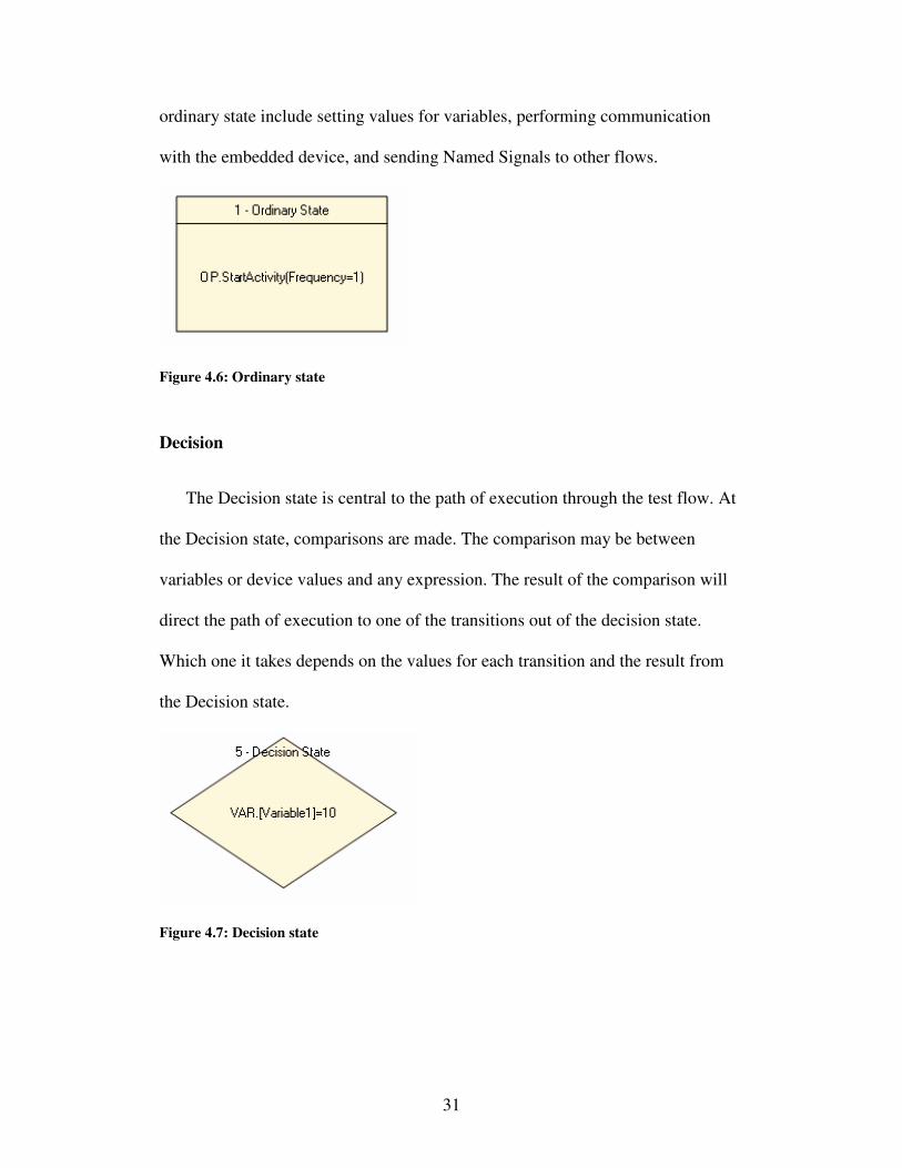
Decision
The Decision state is central to the path of execution through the test flow. At
the Decision state, comparisons are made. The comparison may be between
variables or device values and any expression. The result of the comparison will
direct the path of execution to one of the transitions out of the decision state.
Which one it takes depends on the values for each transition and the result from
the Decision state.
Figure 4.7: Decision state
32
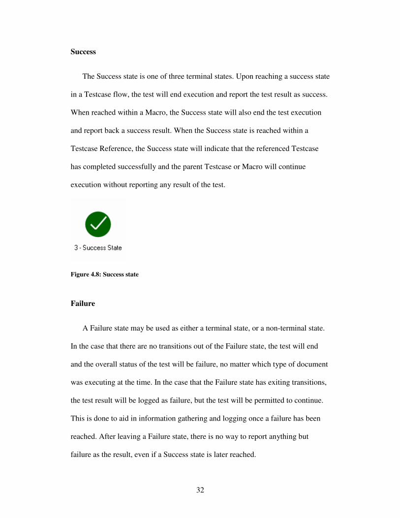
Success
The Success state is one of three terminal states. Upon reaching a success state
in a Testcase flow, the test will end execution and report the test result as success.
When reached within a Macro, the Success state will also end the test execution
and report back a success result. When the Success state is reached within a
Testcase Reference, the Success state will indicate that the referenced Testcase
has completed successfully and the parent Testcase or Macro will continue
execution without reporting any result of the test.
Figure 4.8: Success state
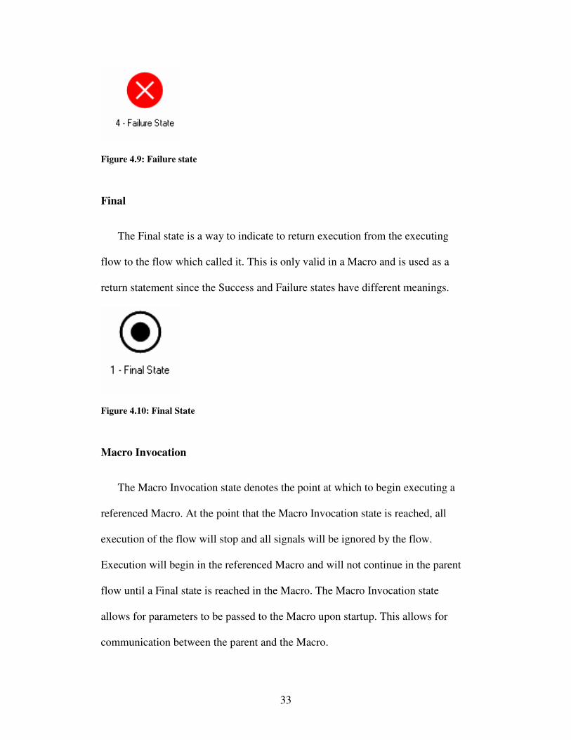
Failure
A Failure state may be used as either a terminal state, or a non-terminal state.
In the case that there are no transitions out of the Failure state, the test will end
and the overall status of the test will be failure, no matter which type of document
was executing at the time. In the case that the Failure state has exiting transitions,
the test result will be logged as failure, but the test will be permitted to continue.
This is done to aid in information gathering and logging once a failure has been
reached. After leaving a Failure state, there is no way to report anything but
failure as the result, even if a Success state is later reached.
33
Figure 4.9: Failure state
Final
The Final state is a way to indicate to return execution from the executing
flow to the flow which called it. This is only valid in a Macro and is used as a
return statement since the Success and Failure states have different meanings.
Figure 4.10: Final State
Macro Invocation
The Macro Invocation state denotes the point at which to begin executing a
referenced Macro. At the point that the Macro Invocation state is reached, all
execution of the flow will stop and all signals will be ignored by the flow.
Execution will begin in the referenced Macro and will not continue in the parent
flow until a Final state is reached in the Macro. The Macro Invocation state
allows for parameters to be passed to the Macro upon startup. This allows for
communication between the parent and the Macro.
34
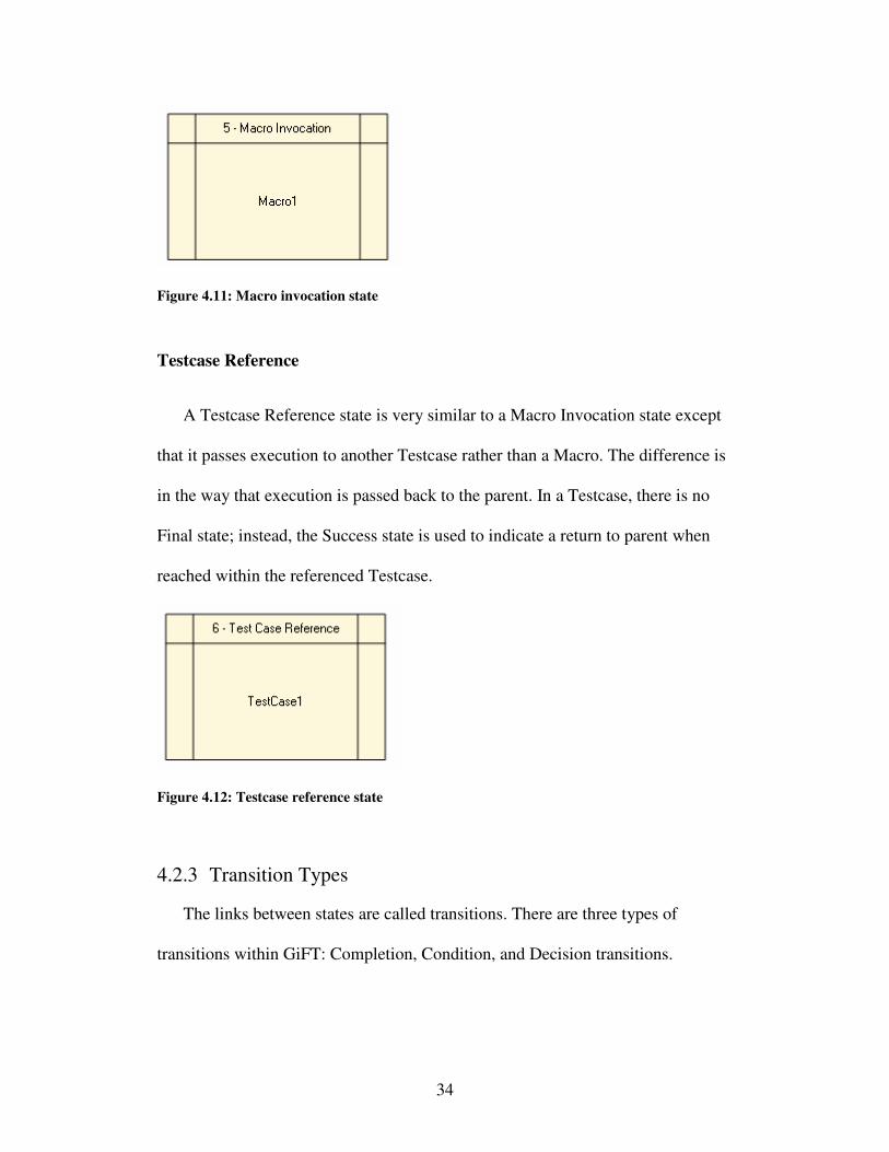
Figure 4.11: Macro invocation state
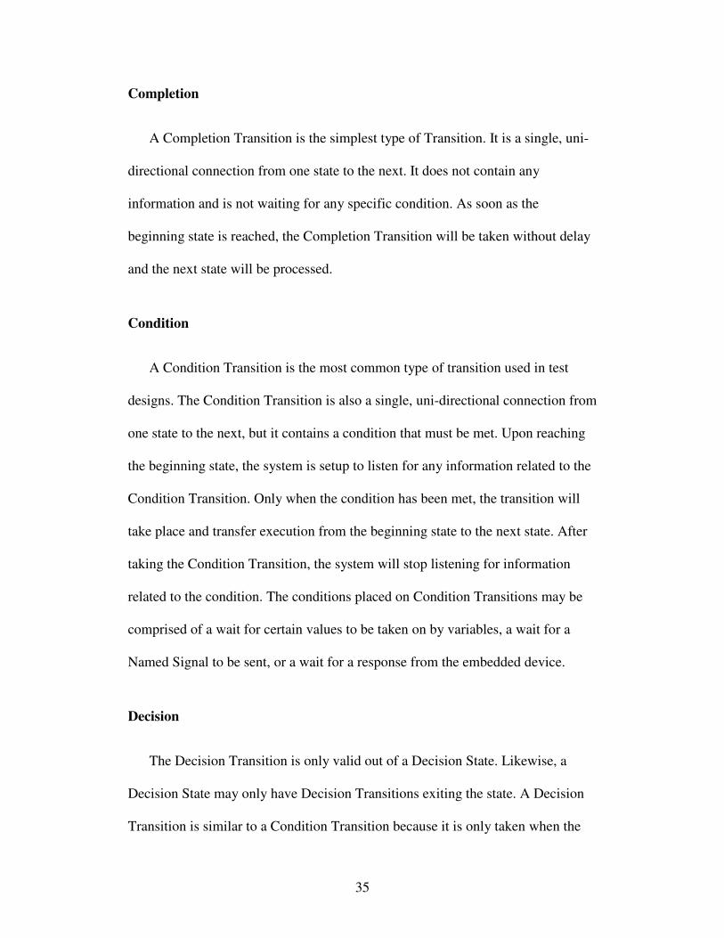
Testcase Reference
A Testcase Reference state is very similar to a Macro Invocation state except
that it passes execution to another Testcase rather than a Macro. The difference is
in the way that execution is passed back to the parent. In a Testcase, there is no
Final state; instead, the Success state is used to indicate a return to parent when
reached within the referenced Testcase.
Figure 4.12: Testcase reference state
4.2.3 Transition Types
The links between states are called transitions. There are three types of
transitions within GiFT: Completion, Condition, and Decision transitions.
35
Completion
A Completion Transition is the simplest type of Transition. It is a single, uni-
directional connection from one state to the next. It does not contain any
information and is not waiting for any specific condition. As soon as the
beginning state is reached, the Completion Transition will be taken without delay
and the next state will be processed.
Condition
A Condition Transition is the most common type of transition used in test
designs. The Condition Transition is also a single, uni-directional connection from
one state to the next, but it contains a condition that must be met. Upon reaching
the beginning state, the system is setup to listen for any information related to the
Condition Transition. Only when the condition has been met, the transition will
take place and transfer execution from the beginning state to the next state. After
taking the Condition Transition, the system will stop listening for information
related to the condition. The conditions placed on Condition Transitions may be
comprised of a wait for certain values to be taken on by variables, a wait for a
Named Signal to be sent, or a wait for a response from the embedded device.
Decision
The Decision Transition is only valid out of a Decision State. Likewise, a
Decision State may only have Decision Transitions exiting the state. A Decision
Transition is similar to a Condition Transition because it is only taken when the
36
condition is met. However, a Decision Transition is usually a comparison that
references the value in the Decision State. For example, the Decision State may
contain the expression “True”. The three Decision Conditions coming out of the
Decision State would be “Result==True”, “Result==False”, and “Else”. In this
case, the Decision Transition with the expression “Result==True” would be taken
and execution would flow to the state at the end of that transition. Each Decision
State must have exactly one “Else” Decision Condition exiting from it. The
“Else” transition is taken in the case that none of the other conditions are satisfied.
4.2.4 Global Handlers
Global handlers add flexibility for a test author. The Global Handler is an
implementation of a watchdog on the test. Global Handlers are specified similarly
to conditions and they are associated with a set of actions to take if the specified
condition is met. The Global Handler is always active and will execute at any
time the condition is met within the scope of the testcase or macro of which it is a
part. Global Handlers add the important ability to monitor for error conditions or
situations that must be triggered upon.
4.2.5 Expression Parsing
To implement comparisons and assignments, there is a need to specify
expressions within GiFT. It is desirable to give the test authors the flexibility that
they had when designing and implementing tests in C++. To this end, a custom
expression parser was developed.
The expression syntax is very similar to C++. The operators all follow very
closely to keep confusion and relearning to a minimum. Once the expression is
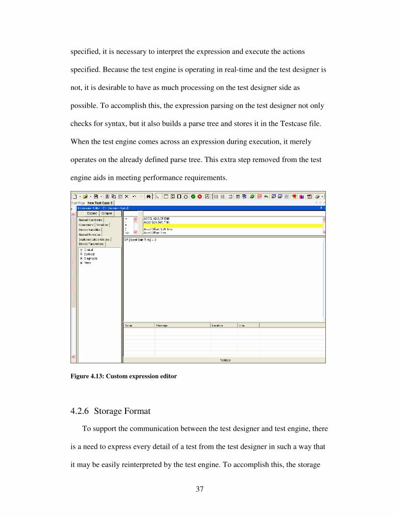
37
specified, it is necessary to interpret the expression and execute the actions
specified. Because the test engine is operating in real-time and the test designer is
not, it is desirable to have as much processing on the test designer side as
possible. To accomplish this, the expression parsing on the test designer not only
checks for syntax, but it also builds a parse tree and stores it in the Testcase file.
When the test engine comes across an expression during execution, it merely
operates on the already defined parse tree. This extra step removed from the test
engine aids in meeting performance requirements.
Figure 4.13: Custom expression editor
4.2.6 Storage Format
To support the communication between the test designer and test engine, there
is a need to express every detail of a test from the test designer in such a way that
it may be easily reinterpreted by the test engine. To accomplish this, the storage
38
format used is XML. The XML format is used for all document types. By using
XML, it is straightforward to express the test documents in a way that may be
readily created by the test designer and readily consumed by the test engine. The
layout of the XML files closely resembles the object structure defined in the Data
Layer of the system. In this regard, the saving and reading of document types is
similar to serializing the object structure on the test designer and de-serializing it
on the test engine. The XML transport paradigm has worked well for
communication between the two applications and it has also lent itself well to the
storage and maintenance of test objects by the testing teams.
4.3 Test Engine
The test engine is where the execution of tests takes place. The test engine is
the topmost piece that sits on a layer of many supporting tools. It is a controller
that moderates the behavior of the test specification while making calls to outside
tools and deciding which actions to take based on the responses from those tools.
The test engine works by first loading up the test files and external files
necessary to interface with the system. It then sets the environment into a known
state, runs some sanity checks on the system, and begins test execution. The test
execution phase involves first setting the state of the system as specified then
initializing each flow of the testcase. Once each flow is initialized, the test engine
is responsible for executing any actions in the testcase by calling out to external
tools and capturing the return information from the tools to operate on. The test
engine receives the input from the tools, makes evaluations against the conditions
39
in the Testcase and moves to the next state of execution in the testcase flow, if
appropriate. The test engine will finish executing when the state of execution
reaches a terminal state, the testcase timer expires, or there is an error
encountered.
4.3.1 Preprocessing
Before any test execution may occur, the Testcase is run through a pre-
processing method. The need for pre-processing is twofold: it checks the Testcase
for errors and it limits the processor-intensive activity to a period in time when the
process does not need to perform in real-time alongside the device under test.
The pre-processing method first checks the Testcase to make sure that the test
contains no validation errors. This check helps to reduce errors during execution
that may cause run-time problems and even put the test system into an
irrecoverable state. The pre-processing check ensures that all necessary references
are available, that there are no datatype mismatches, and that the flows meet a set
of minimum requirements such as having exactly one initial state and a path
between it and a terminal state. After the validation check, the pre-processing
method takes care of loading all of the necessary references so that there is no
disk I/O during test execution. All of the necessary supporting objects are created
in memory and then the test execution may begin.
4.3.2 Flow Processing and Event Processing
After the pre-processing is finished, the test engine sets up the environment
and begins the test execution phase. During this phase, there are two main
activities that are being performed: flow processing and event processing.
40
Flow processing begins by preparing the flows for execution. Each flow’s
initial state is set as the current state. The state to which it is attached is set as the
next state. If there is a condition on the transition, the pieces of the condition are
registered with the test station so that the event will be seen when it happens.
Once the initial states of all the flows are ready, the test engine begins the flow
processing loop.
There is a limitation that the test execution may not utilize Windows’ multi-
threaded ability for each flow; this is due to several factors involving the
architecture of the test station and its critical timing information. Because of this,
the test engine must simulate multi-threaded behavior using one Windows thread.
This is accomplished with a round-robin approach. The flow processing loop goes
one-by-one to each flow and processes it. During the processing, the flow is
checked to see if there are any events that have been delivered to it. If there are,
the events are checked against the currently waiting transition. If the condition is
met, the transition is taken. The “next state” becomes the “current state” and the
connected state moves into the “next state” spot. If there is a completion transition
out of the new “current state” then the transition is taken immediately and the
states and conditions are updated again. Any new conditions are registered and
the actions in the new “current state” are executed. Once the conditions are
registered and the actions have been performed, the test engine moves on to
evaluate the next flow. This continues until a terminal state in any flow becomes
the “current state.”
41
Despite the restriction on using Windows’ multi-threaded ability for each
flow, there is no such restriction in using new threads for utility functions within
the test engine. This allows a separate thread to run for the event processing loop.
The event processing loop is a loop that monitors a queue of incoming events and
delivers them to the appropriate place. When each flow registers for a condition,
the event processing loop is notified that the particular flow is interested in the
event. When the event arrives, the event processing loop will copy the event to
each flow that has registered for it. That is the sole function of the event
processing loop. When the flow processing loop eventually processes the flow, it
will recognize that new events have arrived and will evaluate each pending
condition against the new events.
While there is some room for improvement in the Flow and Event processing
activities, they are currently working quite well within the constraints of the
system. The events are processed and delivered in a timely manner and the flow
state is able to keep up with the speed of the device under test.
4.3.3 Tools
The following sections will describe the tools that the test engine relies upon:
Test System
The test engine operates on a test system platform. The platform hosts two
PCs, a breadboard mockup of the embedded device, a logic analyzer, a digital
interface to the breadboard, a communication interface to the breadboard, and a
tool to provide stimulus. The PCs on the cart control all of the various tools and
42
provide a unified application programming interface to communicate with them
all. The test engine executes on one of the PCs on the test platform and directly
uses the application programming interface (API) to make calls to all of the tools
available.
Digital Interface
The digital interface is a primary component of the test platform. The digital
interface is like a window into the behavior on the breadboard. It is extremely
useful for white box testing since the only alternative is a logic analyzer. The
digital interface can be set up in a way to watch any specific region of the
firmware and to only trigger on specific conditions. These conditions can be
simple “ands” and “ors” or they can be more complex combinations of conditions.
By using the digital interface, the test engine can watch for the conditions to occur
that relate to the condition on a transition within the test flow. Upon satisfaction
of the condition, the test engine is notified and takes the appropriate behavior.
Without the digital interface, the ability to wait for conditions would be severely
limited. The digital interface gives great flexibility and power to the authors of
GiFT tests.
Communication Interface
The communication interface is another primary component of the test
system. The digital interface and communication interface are both responsible
for communicating with the breadboard mockup of the embedded device. The
43
difference between the two is that the digital interface is merely a window into
breadboard activity and may not be used to send information to the device while
the standard communication interface is very similar to the final communication
interface of the shipped embedded system and may be used for bi-directional
communication.
The test system employs the standard communication interface to accomplish
nearly all communication with the device. GiFT allows users to specify the
sending and receiving of communication with the device. To accomplish the
implementation of this communication, the test engine uses the communication
interface to execute the commands that are available to the test authors.
Stimulation Tool
The stimulation tool is another important component of the test system. When
using breadboarding instead of simulating for a testing methodology, there is a
need to create inputs for the breadboard to respond to. The purpose of the
stimulation tool is to simulate input to the embedded device.
In testing, one of the most important activities is providing input to a system
and observing the output. The stimulation tool allows test authors to provide such
input by implementing an application programming interface. The test author may
specify various inputs during design time. When the test engine encounters the
need to simulate activity, it will make a call to the stimulation tool through the
API. The stimulation tool will, in turn, drive inputs into the breadboard while the
44
test engine is observing the behavior through various other means such as the
digital interface and communication interface.
4.4 Test Simulator
While the test engine is well-suited for execution, it is sometimes difficult to
use during development of a test. This is due to the lengthy time it takes to
initialize the test system, the overhead of running the test on the test platform, and
the inability to examine the test until it is completely finished.
To aid with the development of GiFT test design, the test engine simulator
was created. The test engine simulator is a piece of software that may be run
alongside the test designer. It completely emulates the test engine without the
overhead of running the test on an actual test system. In addition, the output of the
test engine simulator is given immediately after each step so that the test
developer may better understand the inner workings of the test. Instead of being
driven by a device or other system tools, the test engine simulator is driven by the
user. After loading the Testcase, the simulator will start the test flows. At the
points where it reaches a waiting condition, the test engine simulator allows the
user to simulate input to the system. When the user provides the simulated input,
the test will continue until the next condition, just as the test would do when
running on the real test engine.
The benefit of providing a test engine simulator becomes apparent when test
authors need to debug through the logic in their tests. After the logic is verified,
45
the test author has eliminated one possible risk factor before running the test
against the real device.
4.5 Post-processing
In the case that a Testcase passes, there is often no further need for analysis.
However, when a test fails, there must be a good support system for investigating
the failure. To this end, the GiFT tool has implemented a key component called
Playback.
Playback is a post-execution visual representation of the test execution.
Because the test system must maintain a high level of processing power to keep
up with the real-time embedded device, there is not enough computing power
available to show diagnostic or debugging information during the test execution.
During execution, logs are created in memory. To prevent slow disk I/O during
test execution, the log files are written to disk after the execution completes. The
problem for test engineers is that the log files are often cryptic and difficult to
understand. In addition, the visual aspect of GiFT is lost if the test engineers are
required to wade through pages of cryptic logs to diagnose a failed Testcase.
Playback is a tool that addresses these issues.
Playback consumes the log files that were created during a test execution as
well as the original Testcase file. Once the files are loaded, test authors are given
a visual representation of their Testcase, similar to the view available in the test
designer. The Playback tool operates similarly to many debugging applications.
Users may step through the execution of a test one step at a time to analyze the
46
path that was taken during execution. The Playback tool also provides some
information about the information received from the device during the test to
explain the reasoning behind taking a certain path.
Playback is a powerful tool for the test authors to visually interpret the
behavior of their tests during execution. It is not only a great diagnostic tool, but
also a great tool to use during the test development phase.
47
Chapter 5
Evaluation
Integration testing has been the main driver of the requirements for GiFT.
Because integration testing requirements for a testing tool are usually a superset
of the requirements for other testing approaches [7], GiFT is easily used for both
integration testing and other less-intensive testing activities. This has caused the
outcome to be extremely well-suited for integration testing without sacrificing the
usability for other testing approaches.
GiFT has been fully implemented and deployed for evaluation. It has been
deployed for unit testing, verification testing, integration testing, ad-hoc testing,
and regression testing. While these different activities have all utilized GiFT at
least minimally, the largest focus has been on integration testing and verification
testing. This evaluation will focus specifically on these two types of testing
activities.
48
5.1 Strengths
The following list illustrates the flaws that exist in the typical approach to
integration and verification testing. Each of these flaws is addressed with the
introduction of GiFT.
Test Engineers must have Low-level Knowledge of the Test System
GiFT has completely removed the low-level detail from the user by directly
executing the user’s graphical test design. The user is only concerned with the
graphical layout of the test design and it is automatically translated into
implementation by the test engine. All of the low-level details are implemented
one time only in the test engine and are hidden from the end users.
Test Maintenance
An important evaluation criterion when comparing testing approaches is the
amount of maintenance required to the repository of developed tests when the
device changes. Ideally, a change in the device is transparent to the test engineer
and the test will continue to execute properly. With the typical testing approach,
the test calls out specific implementation details that may change and require an
update to the test. For example, if the maximum value of a variable called abc is
100, the test would manually call an instruction to set abc = 100. With the advent
of GiFT, the details of the variables are all dynamically loaded. This means that
there is a call to set abc = max. If the maximum value changes in the next release
49
of firmware to 101, the update is handled automatically and no intervention is
required by the test authors.
Limited Re-use
The typical code written for integration and verification tests is written in such
a way that re-use is very limited. There are no pieces that can easily be shared
across multiple testcases; each testcase has to re-implement every part of a
testcase from top to bottom. While the Guidant approach to verification testing
solves this problem minimally by introducing re-usable templates, it doesn’t gain
all the benefits of having re-usable components. GiFT solves this problem by
introducing macros, embedded testcase references, named configurations, and
named conditions. By allowing such flexibility, some testcase designs are as
simple as making calls to pre-defined building blocks and evaluating the result. In
the other approaches, there is an enormous amount of copying and pasting. This
becomes an even larger gain for GiFT because modifying a simple macro used in
many places affects each of the testcases that uses it with only one edit in one
location. With the other approaches, a widespread change could mean modifying
thousands of testcases individually.
Manual Intervention to Capture Results
The typical approach to both integration and verification testing relies heavily
on the logic analyzer to capture results of the testcase. This requires manual setup
of the logic analyzer to trace the variables of interest. When the firmware
50
changes, the locations change and the logic analyzer setup must be changed
accordingly. In GiFT, the details are removed from the user. By using the digital
interface, the need for the logic analyzer is eliminated. The digital interface is
context-aware such that names within the GiFT test will automatically link to the
proper firmware locations, even after a rebuild of the firmware. This eliminates
the need to manually modify logic analyzer setup files to run tests.
Manual Interpretation of Results
Once the typical integration and verification tests are run, the output of the
tests are logic analyzer trace files. These files are manually interpreted to
determine if the conditions match the expected results to indicate a passed
testcase. A more advanced common approach is to use a tool to automatically
process the results. This is an improvement, but the necessary post-processing is
not eliminated. In GiFT, there is no need for post-processing. The test runs in
real-time and the result is also determined in real-time. When the test branches to
a success state, the test result is success; when the test branches to a failure state,
the test result is failure. The result is immediately known upon completion of the
test run.
Difficulty Debugging
Embedded systems tests are notorious for being difficult to debug. Because
the test runs in real-time, the only debugging tool available is usually a re-run of
the test with additional information captured by the logic analyzer. The test
51
engineer then reads cryptic logs and tries to interpret them. The debugging ability
in GiFT is a stark contrast to this manual troubleshooting activity thanks to
extensive logging and an after-the-fact playback tool. The tool allows the user to
step through the results of the test execution with a visual representation of each
action taken, each decision evaluation, and each branch taken in the test flow.
This is a powerful tool to debug both the test and the firmware by comparing the
expected results with the actual results from the test run.
Learning Curve
A new test engineer has a lot to learn when joining an embedded systems
testing group. The test engineer must learn device knowledge, embedded testing
methodology, domain knowledge, and test system knowledge. By using GiFT, the
need to learn test system knowledge is eliminated and the newly hired test
engineer can focus on the more critical aspects of effective testing. In fact, due to
the elimination of implementation, newly hired test engineers need not have any
knowledge of C++. Because of this aspect of GiFT, it would be easy for a testing
group to open the door to many other disciplines outside of software engineers.
To acquire employees with the application knowledge required for effective
testing, the testing group now has the ability to hire domain experts and testing
experts rather than software experts. GiFT also shifts the focus of the testing
activity from software development to effective testing practices.
52
C++ is not Readable and Understandable by Everyone
A large part of the testing process is the review of test designs by groups
outside of the testing organization. These groups may include systems engineers,
domain engineers, or even regulatory oversight. The involvement of outside
groups adds value to test design reviews due to their particular areas of expertise.
While the attendance of outside groups is beneficial in a test review, they are
only helpful when they have an understanding of the contents of the review. In the
case of the typical approach, the usefulness of outside groups reviewing
implementation is limited because members of the outside groups are not software
engineers and generally do not understand C++ code. While they are effective in
reviewing the design of the test, the implementation is not covered. With GiFT,
the design and implementation are one and the same. This makes a test review
very easy to understand and eliminates the need for a test implementation review.
The elimination of a test implementation review is a large time savings for
everyone involved in the review process. In addition, the GiFT test designs are
graphical in nature and will often lead to higher understanding of the test design
than a procedural text description of a test design.
5.2 Weaknesses
While GiFT has many advantages over the other testing approaches, there are
also a handful of disadvantages. Some of these disadvantages are common to all
available testing approaches, while others are unique to GiFT. They are illustrated
below:
53
Digital Interface Performance
To ease information passing between the test station and the system under
test, GiFT relies heavily on the digital interface to the device. Due to speed and
hardware limitations, the particular implementation of the digital interface used
for the evaluation of GiFT was only able to monitor up to 120 different firmware
locations. In verification tests, this is often adequate because of the generally
smaller size of verification tests. In integration tests this limitation has been a
problem, but only in a few, limited cases. The alternative testing approaches also
utilize the digital interface and therefore have a similar limitation. All approaches
using the digital interface have a significant advantage over the previous
approaches that used the logic analyzer because the logic analyzer only provided
the ability to monitor 16 locations at a time.
System Speed
To test a non-emulated real-time device, the test system must be able to keep
up with the real-time device and not fall behind in its execution. This becomes a
limitation when there is a high traffic load placed on the communication interface
between the device and the test system. When the digital interface has a large
number of locations to monitor and the locations are commonly updated, there is
an enormous amount of communication that must happen between the device and
test system. In some cases, the test system is unable to process all of the events
before the next execution step of the device. In this case, the test system and
device are out of sync and the test will not execute appropriately. Because of this
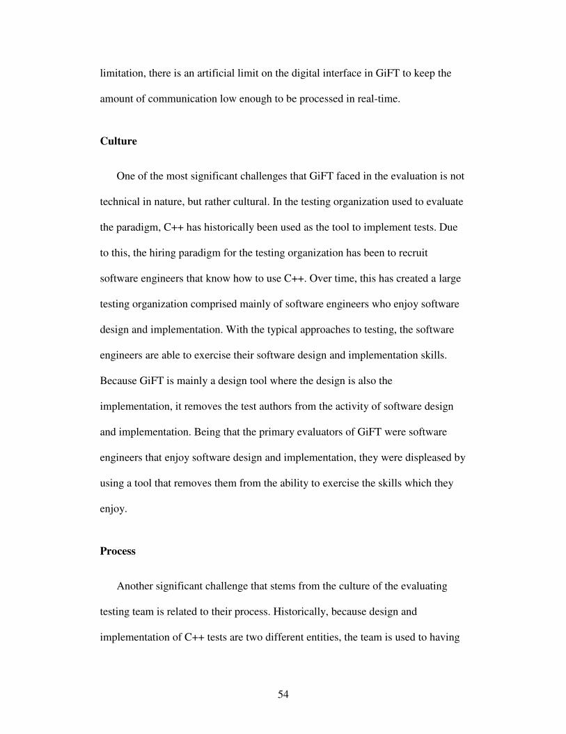
54
limitation, there is an artificial limit on the digital interface in GiFT to keep the
amount of communication low enough to be processed in real-time.
Culture
One of the most significant challenges that GiFT faced in the evaluation is not
technical in nature, but rather cultural. In the testing organization used to evaluate
the paradigm, C++ has historically been used as the tool to implement tests. Due
to this, the hiring paradigm for the testing organization has been to recruit
software engineers that know how to use C++. Over time, this has created a large
testing organization comprised mainly of software engineers who enjoy software
design and implementation. With the typical approaches to testing, the software
engineers are able to exercise their software design and implementation skills.
Because GiFT is mainly a design tool where the design is also the
implementation, it removes the test authors from the activity of software design
and implementation. Being that the primary evaluators of GiFT were software
engineers that enjoy software design and implementation, they were displeased by
using a tool that removes them from the ability to exercise the skills which they
enjoy.
Process
Another significant challenge that stems from the culture of the evaluating
testing team is related to their process. Historically, because design and
implementation of C++ tests are two different entities, the team is used to having
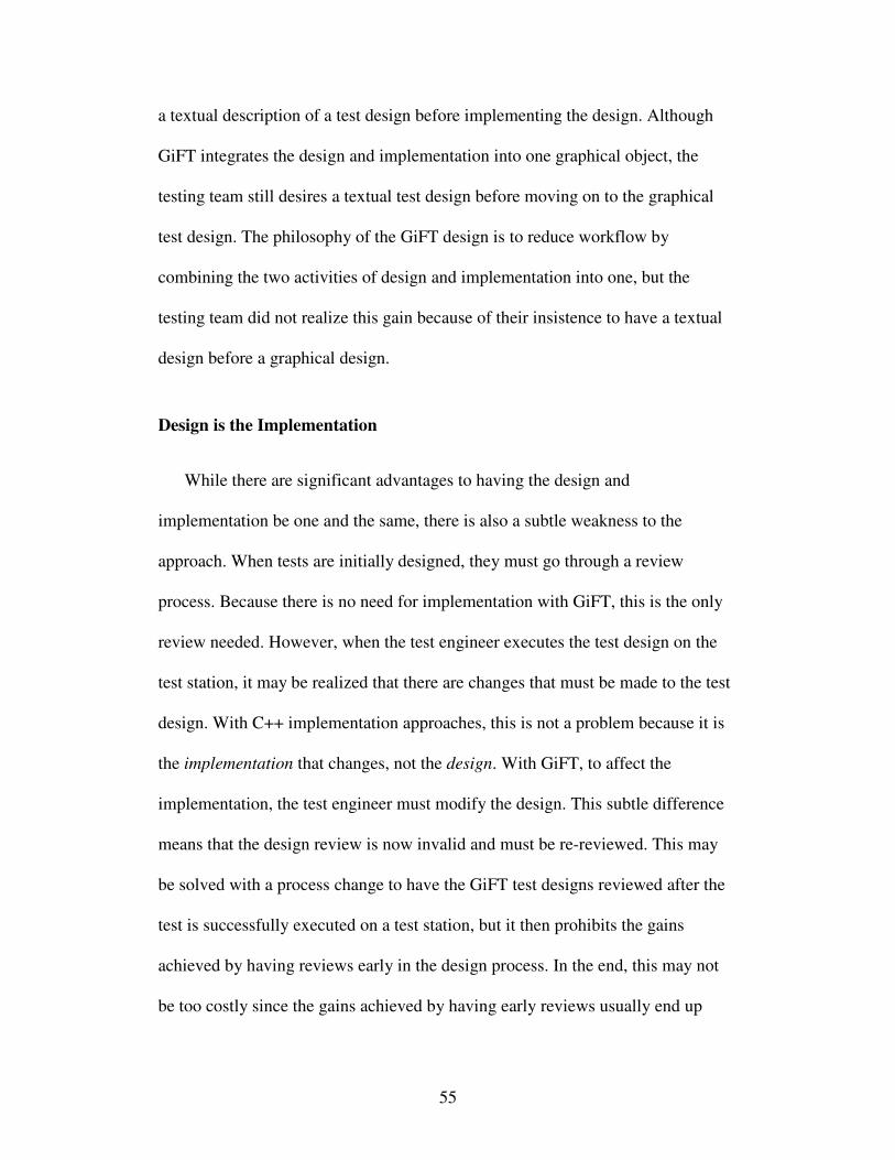
55
a textual description of a test design before implementing the design. Although
GiFT integrates the design and implementation into one graphical object, the
testing team still desires a textual test design before moving on to the graphical
test design. The philosophy of the GiFT design is to reduce workflow by
combining the two activities of design and implementation into one, but the
testing team did not realize this gain because of their insistence to have a textual
design before a graphical design.
Design is the Implementation
While there are significant advantages to having the design and
implementation be one and the same, there is also a subtle weakness to the
approach. When tests are initially designed, they must go through a review
process. Because there is no need for implementation with GiFT, this is the only
review needed. However, when the test engineer executes the test design on the
test station, it may be realized that there are changes that must be made to the test
design. With C++ implementation approaches, this is not a problem because it is
the implementation that changes, not the design. With GiFT, to affect the
implementation, the test engineer must modify the design. This subtle difference
means that the design review is now invalid and must be re-reviewed. This may
be solved with a process change to have the GiFT test designs reviewed after the
test is successfully executed on a test station, but it then prohibits the gains
achieved by having reviews early in the design process. In the end, this may not
be too costly since the gains achieved by having early reviews usually end up
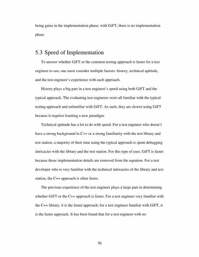
56
being gains in the implementation phase; with GiFT, there is no implementation
phase.
5.3 Speed of Implementation
To answer whether GiFT or the common testing approach is faster for a test
engineer to use, one must consider multiple factors: history, technical aptitude,
and the test engineer’s experience with each approach.
History plays a big part in a test engineer’s speed using both GiFT and the
typical approach. The evaluating test engineers were all familiar with the typical
testing approach and unfamiliar with GiFT. As such, they are slower using GiFT
because it requires learning a new paradigm.
Technical aptitude has a lot to do with speed. For a test engineer who doesn’t
have a strong background in C++ or a strong familiarity with the test library and
test station, a majority of their time using the typical approach is spent debugging
intricacies with the library and the test station. For this type of user, GiFT is faster
because those implementation details are removed from the equation. For a test
developer who is very familiar with the technical intricacies of the library and test
station, the C++ approach is often faster.
The previous experience of the test engineer plays a large part in determining
whether GiFT or the C++ approach is faster. For a test engineer very familiar with
the C++ library, it is the faster approach; for a test engineer familiar with GiFT, it
is the faster approach. It has been found that for a test engineer with no
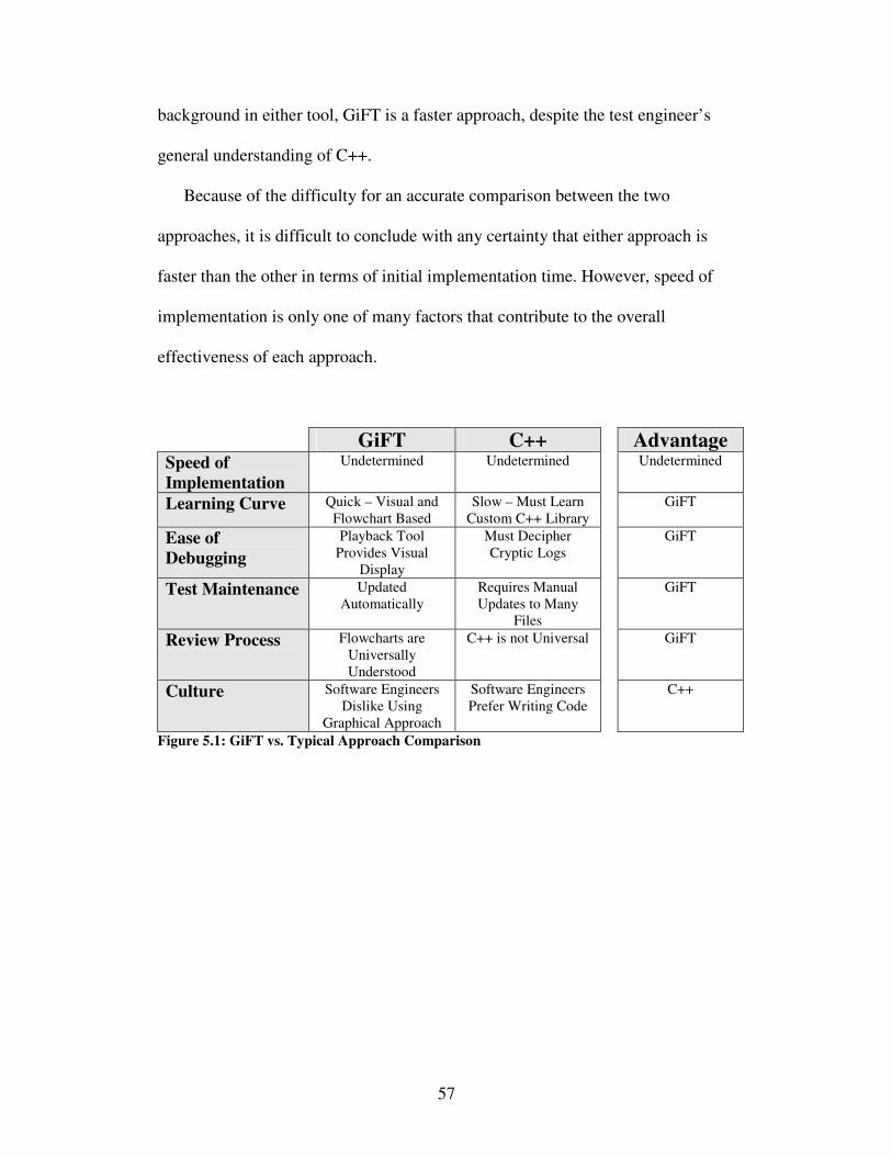
57
background in either tool, GiFT is a faster approach, despite the test engineer’s
general understanding of C++.
Because of the difficulty for an accurate comparison between the two
approaches, it is difficult to conclude with any certainty that either approach is
faster than the other in terms of initial implementation time. However, speed of
implementation is only one of many factors that contribute to the overall
effectiveness of each approach.
GiFT C++ Advantage Speed of
Implementation
Undetermined Undetermined Undetermined
Learning Curve Quick – Visual and
Flowchart Based
Slow – Must Learn
Custom C++ Library
GiFT
Ease of
Debugging
Playback Tool
Provides Visual
Display
Must Decipher
Cryptic Logs
GiFT
Test Maintenance Updated
Automatically
Requires Manual
Updates to Many
Files
GiFT
Review Process Flowcharts are
Universally
Understood
C++ is not Universal GiFT
Culture Software Engineers
Dislike Using
Graphical Approach
Software Engineers
Prefer Writing Code
C++
Figure 5.1: GiFT vs. Typical Approach Comparison
58
Chapter 6
Future Work
While GiFT has proven to be an effective testing approach for many various
types of testing activities, there are still opportunities for improvement. The
potential improvements include moving to a real-time operating system, moving
to a more powerful and re-designed test system, modifying it for even broader
testing use, implementing numerous GUI enhancements.
Currently, the test engine executes on a test system that runs Windows as its
operating system. Due to the fact that GiFT executes on the Windows operating
system, there is a lack of the ability to have complete control over the test station.
It has been noted several times that Windows will execute a processor-intensive
task during a time-critical portion of a test execution. These cases cause non-
deterministic behavior to be exhibited by the test system. In the future, it would be
worthwhile to experiment with a real-time operating system to eliminate the non-
deterministic behavior and gain complete control of the test station.
The test station used for evaluation of GiFT is a conglomeration of many
individual components that were independently designed before being melded
together. The lack of a central system design has led to some deficiencies that
59
would be worthwhile to address during a test station re-design. At the same time,
the system could be designed to benefit from the latest dual and quad core
technology. With a proper test system design in place and the latest technology,
GiFT could potentially increase the amount of information from the device that it
is able to process. This will further empower test engineers with more test design
flexibility.
GiFT is currently focused on testing embedded devices. While firmware
testing has been the focus, there exist many additional products that may benefit
from using GiFT as a testing approach. For example, many embedded devices
have external instruments that communicate with the embedded device. The
testing of these communication devices is a large effort that could potentially
benefit from using GiFT if the right modifications are put into place to enable
GiFT to interface with it.
During the development of GiFT, the paradigm was always to focus mostly on
the functionality of the system. This development process has resulted in an
application that works very well, but it also leaves room for improvement to the
graphical user interface. Improving the usability will make the experience of
using GiFT much more pleasant and potentially more effective.
While GiFT itself has some areas for improvement, there is also room for
improvement in its evaluation. GiFT has been thoroughly compared against the
common testing approach, but it has not been compared against other cutting-edge
testing techniques. It would be worthwhile to rigorously evaluate GiFT against
other innovative testing approaches.
60
Chapter 7
Concluding Remarks
The Graphical interface Flowchart Tool (GiFT) approach has shown to be
effective in improving testing, especially related to the areas of integration and
verification testing. The common testing paradigm and the approach to
verification testing at Guidant both have significant downfalls that are addressed
and improved upon with GiFT.
GiFT is a unique approach to testing software because it isolates the test
engineer from software implementation details. The evaluating testing group is
mainly comprised of software engineers; the departure from test implementation
is looked at as a detriment because of their fondness of software development.
The reason for hiring software engineers into the testing group is historically due
to the fact that the software engineering skill set was necessary to implement test
designs. The GiFT tool has eliminated the need for test engineers to possess
software engineering skills. With this new approach, testing organizations have
the opportunity to become more effective because they are no longer limited to
hiring software developers as test engineers. With GiFT, testing organizations
have the ability to hire testing experts or domain experts to perform testing that

61
may add an additional level of testing performance not possible with a software
engineer.
The first version of GiFT has proven to be an effective testing tool. Whether it
will overcome cultural barriers and gain broader acceptance still remains to be
seen.
62
Bibliography
[1] Altman, Lawrence K. “Heart Device Recall Poses a Quandary for Patients.”
New York Times 16 October 2007.
[2] Auriga, Inc. Testing of Embedded Software Products. Auriga, Inc. home
page. 2 Nov. 2008
<http://www.auriga.com/files/projects/Auriga_test_of_emb_sw_prod.pdf>.
[3] Bajaj, Vikas. “F.D.A. Puts Restrictions on Guidant.” New York Times 28
December 2005.
[4] Balakrishnan, Subhashini, and Sofiene Tahar. “A Hierarchical Approach to
the Formal Verification of Embedded Systems Using MDGs.” In Proc. of
the Ninth Great Lakes Symposium on VLSI (1999): 284.
[5] Balarin, Felice, et al. “Formal Verification of Embedded Systems based on
CFSM Networks.” DAC '96: Proceedings of the 33rd annual conference on
Design automation (1996): 568-571.
[6] Beizer, Boris. Software Testing Techniques. 2nd
Ed. New York: Van
Nostrand Reinhold, 1990.
[7] Beizer, Boris. Black-Box Testing. New York: John Wiley & Sons, Inc.,
1995.
[8] Beyeda, Sami, Volker Gruhn, and Michael Stachorski. “A Graphical Class
Representation for Integrated Black- and White-Box Testing.” In Proc. of
the IEEE International Conference on Software Maintenance (2001): 706.
[9] Boniol, Frederic, Virginie Wiels, and Emmanuel Ledinot. “Experiences in
using model checking to verify real time properties of a landing gear
control system.” Presented at the European Congress ERTS, 2006.
[10] Broekman, Bart, and Edwin Notenboom. Testing Embedded Software.
London: Pearson Education Limited, 2003.
63
[11] Broy, Manfred. “Requirements Engineering for Embedded Systems.” 1997.
Technische Universität München, Institut für Informatik. 19 Oct. 2008
<http://www4.in.tum.de/publ/papers/femsys_boesswet_1997_Conference.p
df>.
[12] Burnstein, Ilene. Practical Software Testing. New York: Springer-Verlag,
2003.
[13] Dasdan, A., D. Ramanathan, and R. Gupta. “An interactive validation
methodology for embedded systems.” In Proc. High-Level Design
Validation and Test Workshop (1997): 123-130.
[14] Devaraj, George, Mats P. E. Heimdahl, and Donglin Liang. Condition
based coverage criteria: To use or not to use, that is the question. 2005. U
of Minnesota, Minneapolis. 19 Oct. 2008 <http://www-
users.cs.umn.edu/~devaraj/paper.pdf>.
[15] Easterbrook, Steve, and John Callahan. “Formal Methods for Verification
and Validation of partial specifications: A Case Study.” Journal of Systems
and Software 40 (1998).
[16] Encontre, Vincent. “Testing embedded systems: Do you have the GuTs for
it?” The Rational Edge (2003). 19 Oct. 2008
<http://www.ibm.com/developerworks/rational/library/459.html>.
[17] Fowler, Kim R. What Every Engineer Should Know About Developing
Real-Time Embedded Products. Boca Raton, Florida: CRC Press, 2008.
[18] Goddard, Steve. “Analyzing the Real-Time Properties of a Dataflow
Execution Paradigm using a Synthetic Aperture Radar Application.” In
Proc. of the 3rd IEEE Real-Time Technology and Applications Symposium
(1997): 60.
[19] Gustafson, David A. Schaum's Outline of Theory and Problems of Software
Engineering. New York: McGraw-Hill, 2002.
[20] Hammer, Eric M. Logic and Visual Information. Stanford, California: CSLI
Publications, 1995.
[21] Harrison, Neil B. “Testing: It’s Part of Your Job - Make it Effective!”
Presented at the International Conference on Object-Oriented
Programming, Systems, Languages and Applications (2007).
[22] Heitmeyer, C., et al. “Tools for Formal Specification, Verification, and
Validation of Requirements.” In Proc. 12th Annual Conf. on Computer
Assurance (1997): 35-47.
64
[23] Holzmann, Gerard J., and Margaret H. Smith. “Automating software feature
verification.” Bell Labs Technical Journal (2005): 72-87.
[24] Horowitz, Paul, and Winfield Hill. The Art of Electronics. Cambridge
[England]: Cambridge University Press, 1989.
[25] Jahanian, Farnam. “Run-Time Monitoring of Real-Time Systems.”
Advances in Real-time Systems. Ed. Sang H. Son. New Jersey: Prentice
Hall, 1995. 435-460.
[26] Jorgensen, Paul. Software Testing: A Craftsman’s Approach. 3rd
Ed. Boca
Raton, Florida: Auerbach Publications, 2008.
[27] Larsen, Kim G., Marius Mikucionis, and Brian Nielsen. “Online Testing of
Real-time Systems Using Uppaal.” Formal Approaches to Software Testing
3395 (2005): 79-94.
[28] Larsen, K. G., et al. “Testing real-time embedded software using UPPAAL-
TRON: an industrial case study.” In Proc. of the 5th ACM international
Conference on Embedded Software (2005): 299-306.
[29] Loveland, Scott, et al. Software Testing Techniques. Hingham,
Massachusetts: Charles River Media, 2005.
[30] Marwedel, P. Embedded System Design. Secaucus, New Jersey: Springer-
Verlag New York, Inc., 1986.
[31] Meier, Barry. “Citing Flaws, Maker Recalls Heart Devices.” New York
Times 18 June 2005.
[32] Myers, Glenford J. The Art of Software Testing. 2nd
Ed. Hoboken, New
Jersey: Wiley, 2004.
[33] Perry, William E. Effective Methods for Software Testing. 2nd
Ed. New
York: Wiley, 2000.
[34] Perry, William E. How to Test Software Packages. New York: Wiley, 1986.
[35] Pike, L. Formal Verification of Time-Triggered Systems. Diss. Indiana U,
2006. UMI: AAI3215296.
[36] Sommerville, Ian. Software Engineering. International computer science
series. Boston: Pearson/Addison-Wesley, 2004.
65
[37] Staunstrup, Jorgen, et al. “Practical Verification of Embedded Software.”
Computer 33.5 (2000): 68-75.
[38] Steiner, Neil, and Peter Athanas, “Hardware-Software Interaction:
Preliminary Observations.” In Proc. of the 12th Reconfigurable
Architectures Workshop, RAW (2005).
[39] Tan, Li. Evidence-Based Verification. Diss. State U of New York at Stony
Brook, 2002. Proquest UMI, 2002. 764991991.
[40] Tan, Li, Oleg Sokolsky, and Insup Lee. “Specification-based Testing with
Linear Temporal Logic.” In Proc. of the 2004 IEEE International
Conference on Information Reuse and Integration (2004): 493-498.
[41] Tsai, Wei-Tek, et al. “Rapid Embedded System Testing Using Verification
Patterns.” IEEE Software 22.4 (2005): 68-75.
[42] U.S. FDA, Design Control Guidance for Medical Device Manufacturers,
March 11, 1997. http://www.fda.gov/cdrh/comp/designgd.pdf.
[43] U.S. FDA, General Principles of Software Validation; Final Guidance for
Industry and FDA Staff, January 11, 2002.
http://www.fda.gov/cdrh/comp/guidance/938.pdf.
[44] Winters, Brian D., and Alan J. Hu. “Source-Level Transformations for
Improved Formal Verification.” In Proc. of IEEE International Conference
on Computer Design (2000): 599.
[45] Zhu, Feng. A Requirement Verification Framework for Real-time
Embedded Systems. Diss. Univ. of Minnesota, 2002. Proquest UMI, 2002.
727387361.