Embed Size (px)
Citation preview

308 https://doi.org/10.1107/S2053273318007441 Acta Cryst. (2018). A74, 308–321
research papers
A group-theoretical approach to enumeratingmagnetoelectric and multiferroic couplings inperovskites
Mark S. Senna* and Nicholas C. Bristoweb,c
aDepartment of Chemistry, University of Warwick, Gibbet Hill, Coventry, CV4 7AL, UK, bSchool of Physical Sciences,
University of Kent, Canterbury CT2 7NH, UK, and cDepartment of Materials, Imperial College London, London SW7
2AZ, UK. *Correspondence e-mail: [email protected]
A group-theoretical approach is used to enumerate the possible couplings
between magnetism and ferroelectric polarization in the parent Pm3m
perovskite structure. It is shown that third-order magnetoelectric coupling
terms must always involve magnetic ordering at the A and B sites which either
transforms both as R-point or both as X-point time-odd irreducible
representations (irreps). For fourth-order couplings it is demonstrated that this
criterion may be relaxed allowing couplings involving irreps at X-, M- and R-
points which collectively conserve crystal momentum, producing a magneto-
electric effect arising from only B-site magnetic order. In this case, exactly two of
the three irreps entering the order parameter must be time-odd irreps and either
one or all must be odd with respect to inversion symmetry. It is possible to show
that the time-even irreps in this triad must transform as one of: X1+, M3,5
� or R5+,
corresponding to A-site cation order, A-site antipolar displacements or anion
rocksalt ordering, respectively. This greatly reduces the search space for type-II
multiferroic perovskites. Similar arguments are used to demonstrate how weak
ferromagnetism may be engineered and a variety of schemes are proposed for
coupling this to ferroelectric polarization. The approach is illustrated with
density functional theory calculations on magnetoelectric couplings and, by
considering the literature, suggestions are given of which avenues of research
are likely to be most promising in the design of novel magnetoelectric materials.
1. Introduction
The classification of distortions in functional materials is an
important part of the process of understanding the structure–
property relationship. Perovskites (ABX3) are among the
most studied systems, which is in part due to the many func-
tional properties that they exhibit, but also due to their rich-
ness in structural distortions and phase transitions. Schemes
classifying the ubiquitous rotations and tilts of the quasi-rigid
BO6 octahedra that drive many of these phase transitions in
perovskites can be conveniently classified in terms of Glazer
notation (Glazer, 1972), and other such schemes also exist
for classifying distortions in layered perovskite such as
Ruddlesden–Poppers (Aleksandrov & Bartolome, 1994).
While these schemes have enjoyed much success due to their
intuitive nature, there are several limitations, in particular that
they are not easily generalized to different systems. Even
within the perovskite family, with additional symmetry
breaking with respect to the ABX3 aristotype, it is no longer
clear how the occurrence of tilts and rotations can be unam-
biguously described, or indeed how the symmetry lowering
implied by the combined orderings can be derived.
More formally, the degrees of freedom in an aristotype
‘parent’ structure, such as the Pm3m ABX3 perovskite, may be
ISSN 2053-2733
Received 10 January 2018
Accepted 17 May 2018
Edited by L. Bourgeois, Monash University,
Australia
Keywords: magnetoelectric couplings;
multiferroic couplings; perovskites; improper
ferroelectricity; group theory; irrep analysis;
anharmonic couplings.

defined as transforming as irreducible representations (irreps)
of the parent space group (and setting). The irreps for all
special positions in reciprocal space have been tabulated by
various authors including by Bradley & Cracknell (1972),
Miller & Love (1967), Kovalev (1993) and more recently also
at non-special k-points (Stokes et al., 2013). With knowledge of
these irreps, it is possible to compute the isotropy subgroups of
the 230 space groups (Stokes & Hatch, 1988), which are the
subgroups accessible due to the action of an order parameter
(OP) transforming as one of these irreps.
Online tools such as ISODISTORT (Campbell et al., 2006)
and AMPLIMODES on the Bilbao Crystallographic Server
(Aroyo et al., 2006; Orobengoa et al., 2009) allow distorted
structures to be easily decomposed in terms of irreps of a
parent space group, and it is now possible to superpose up to
three irreps with associated independent incommensurate
propagation vectors, and derive the possible subgroups and
secondary order parameters (SOPs) (Stokes & Campbell,
2017). Additionally, these programs now generate outputs that
can be directly read by Rietveld and single-crystal refinement
programs (Campbell et al., 2007; Perez-Mato et al., 2010),
allowing refinements to be performed in a symmetry-adapted
basis and facilitating easy identification of the active order
parameters in a given phase transition.
As a result of much of this work, several group-theoretical
studies have emerged that have more formally classified
distortions in perovskite-related materials. These include
group-theoretical analysis of octahedral tilting in perovskites
(Howard & Stokes, 1998, 2005; Knight, 2009), cation-ordered
and Jahn–Teller distortions in perovskites (Howard &
Carpenter, 2010), ferroelectric perovskites (Stokes et al.,
2002), anion ordering (Talanov et al., 2016), and works on
layered Ruddlesden–Poppers (Hatch & Stokes, 1987; Hatch et
al., 1989). One particularly valuable aspect of classifying these
distortions in the formal language of irreps is to understand
physical phenomena that can arise due to secondary order
parameters which feature at linear order in the Landau-style
free energy potential. These odd order terms may always
adopt a sign such that they act to lower the overall free energy
and hence symmetry analysis alone is sufficient to identify
their instability. The process of ascertaining these couplings is
greatly simplified using the ideas of invariants analysis (Stokes
& Hatch, 1991; Saxena et al., 1994) when constructing the
Landau-style free energy expansion about the parent undis-
torted phase, and online tools for doing this also exist (Hatch
& Stokes, 2003).
This process is particularly valuable when understanding
improper ferroelectricity (Levanyuk & Sannikov, 1974) where
third-order terms in the free energy expansion are invariably
the key to understanding the resulting polarization. This area
has enjoyed a renaissance in the form of the recently much
discussed ‘hybrid improper ferroelectric’ mechanism [e.g. see
Benedek et al. (2015) for a recent review]. The powerful use of
magnetic superspace groups for describing multiferroic
materials has also allowed magnetoelectric couplings to be
trivially identified through analysis of secondary order para-
meters (Perez-Mato et al., 2012). Antisymmetric exchange
arguments with respect to the parent perovskite structure
have also been used to explain the dominant anisotropic terms
that control the directions of spin ordering (Khalyavin et al.,
2015). And of course, the occurrence of weak ferromagnetism
(wFM) by the Dzyaloshinsky–Moriya (DM) interaction
(Dzyaloshinsky, 1958; Moriya, 1960) was first originally
rationalized based on such symmetry arguments alone
(Dzyaloshinsky, 1958).
Using many of the ideas above, and with the aid of the
ISODISTORT (Campbell et al., 2006) tool, we seek here to
generalize a recipe for inducing magnetoelectricity in the
parent Pm3m perovskite. These recipes are based on
symmetry arguments alone, and we use as the ingredients
structural and magnetic degrees of freedom, which we classify
in terms of transforming as irreps of the parent space group.
Our results clearly show why certain kinds of coupled distor-
tions and magnetic ordering can never lead to ferroelectric or
ferromagnetic secondary order parameters, and by consid-
ering which orderings and cation arrangements are commonly
observed, we are able to identify several promising avenues
for further investigation.
The article is arranged as follows. In x2, we first classify the
ingredients for symmetry breaking that are at our disposal in
terms of irreps of the parent Pm3m space group. To keep our
results as general as possible, we will also describe cation and
anion ordering in terms of irreps, rather than forming new
parent space groups. We then proceed to give various recipes
for achieving (multi)ferroic orderings as a consequence of
different symmetry-breaking distortions. In x3, for complete-
ness we give the recipe for (hybrid) improper ferroelectricity,
while in xx4, 5, 6 we discuss magnetoelectric couplings arising
due to third- and fourth-order terms in the free energy
expansion. As the most useful multiferroics are those that are
ferromagnets (rather than antiferromagnets), in x7 we explain
how similar ideas can be used to design systems that exhibit
wFM. We also consider in this section systems in which either
polarization (P) or wFM is supplied as an external order
parameter (as a magnetic or electric field) resulting in the
development of wFM or P, respectively, in response to the
stimuli. Finally, in x8 we put all of our above ideas together and
deal with the design of materials that are both wFM and
ferroelectric, and have indirect coupling through at least one
primary order parameter (POP).
2. Ingredients for symmetry breaking
First we classify the magnetic degrees of freedom at our
disposal in terms of irreps of the space group Pm3m. We
classify all of these in terms of irreps of the parent perovskite
structure Pm3m with setting A 1a (0, 0, 0); B 1b (12,
12,
12); X 3c
(0, 12,
12). We note that reversing the setting of the structure will
result in many of the irrep labels changing, in particular at the
X- and R-points, irreps labelled as ‘+’ will correspond to
another numbered irrep with the ‘�’ sign and vice versa. The
origin of this is that the sign part in these irrep labels refers to
whether or not parity (with respect to inversion symmetry) is
conserved or violated at the origin (0, 0, 0), and hence inter-
research papers
Acta Cryst. (2018). A74, 308–321 Senn and Bristowe � Magnetoelectric and multiferroic couplings in perovskites 309

changing the atom at the origin naturally affects the distor-
tions physically being described by a particular representation.
The orderings of the magnetic degrees of freedom will ulti-
mately be devised in such a way as to drive secondary order
parameters that are related to ferroelectricity. We restrict
ourselves here to the basic types of antiferromagnetic ordering
which are commonly observed in perovskites. These are often
characterized as A, C and G type having one, two and three
antiferromagnetic (AFM) nodes, respectively. They may be
classified as corresponding to orderings which transform as
irreps at the X[0, 12, 0]-, M[1
2,12, 0]- and R[1
2,12,
12]-points (Fig. 1). It
is important to note that magnetic structures such as Ax and
Ayz, which correspond to an ordering with propagation vector
X[12, 0, 0] with moment along the propagation axis and
perpendicular to it, transform as distinct irreps in this analysis,
and will imply physically distinct secondary order parameters.
This forms the basis of the antisymmetric exchange arguments
of Khalyavin et al. (2015) to determine spin (exchange)
anisotropy, and this is why this analysis is so powerful in the
perovskite structure where the magnetic atoms sit on high-
symmetry sites. Fig. 1 gives full details of how the spin
arrangements are related to irreps.
Next we classify the various structural degrees of freedom
within the perovskite structure for inducing symmetry-
lowering phase transitions. The ingredients at our disposal are
the commonly observed octahedral rotation and tilt modes,
Jahn–Teller distortion modes, cation (charge) ordering modes,
antipolar modes and strain. These are all listed in Table 1,
along with their corresponding labels in the alternative setting
[A at (12,
12,
12)]. Some of these degrees of freedom will be
accessible via physical control parameters (such as application
of epitaxial strain) whilst others only by chemical design (for
example, by inclusion of Jahn–Teller active cations). In the
analysis, we will also classify cation and anion orderings in
the perovskite structure in terms of transforming as irreps of
the parent perovskite. For example, rocksalt cation ordering at
the B site transforms as R�2 and A-site layered cation order as
Xþ1 . We may even classify the highly distorted cation-ordered
A0A3B4O12 quadruple perovskite with aristotype Im3 as
having cation orderings transform as M1+ [with three k-actives
= (12,
12, 0); (0, 1
2,12); (1
2, 0, 12)] and octahedral rotations that
stabilize the A0 square-planar coordination transforming as
M2+.
Finally, the desired property, ferroelectricity, transforms as
the polar mode belonging to the irrep ��4 . ��4 is a three-
dimensional irrep; the most general order parameter direction
(OPD) associated with this would hence be written as
OP(a,b,c), where special directions (a, 0, 0), (a, a, 0) and (a, a,
a) correspond to tetragonal, orthorhombic and rhombohedral
directions, respectively, for the macroscopic polarization and
off-centre displacements of the atoms. For a full discussion of
notation relating to OPDs, including cases where multiple
irreps enter into the OP, as will become pertinent in future
discussion, the reader is directed to Appendix A. Please note
that throughout this article we choose to list the full OPD,
instead of the space group and setting. The two are equivalent,
but we choose the OPD for the sake of brevity, and also due to
310 Senn and Bristowe � Magnetoelectric and multiferroic couplings in perovskites Acta Cryst. (2018). A74, 308–321
research papers
Figure 1Basic AFM magnetic orderings of the perovskite structure withassociated irrep labels and illustrated along high-symmetry OPD A sites,B sites and X sites are shown as green, red and blue spheres, respectively.The parent cubic unit cell is shown in pink so as to illustrate therelationship with the new crystallographic axes (grey). All figures aredrawn in ISODISTORT.
Table 1Ingredients for symmetry breaking in the perovskite structure, classified in terms of transforming as irreps of the parent perovskite structure, with the Asite at the origin (the corresponding irrep labels for the setting with the B site at the origin are given in parentheses).
Ingredient � X M R
Strain �þ3 ; �þ5Cation order (A) Xþ1 (X�3 ) Mþ1 (Mþ4 ) Rþ1 (R�2 )Cation order (B) X�3 (Xþ1 ) Mþ4 (Mþ1 ) R�2 (Rþ1 )Anion order (O) Xþ1 (X�3 ) Mþ4 (Mþ1 ); M�5 (M�5 ) Rþ5 (R�4 )(Anti-)Polar (A) ��4 X�3 (Xþ1 ); X�5 (Xþ5 ) M�3 (M�2 ); M�5 (M�5 ) R�4 (Rþ5 )(Anti-)Polar (B) ��4 Xþ1 (X�3 ); Xþ5 (Xþ5 ) M�2 (M�3 ); M�5 (M�5 ) Rþ5 (R�4 )Jahn–Teller modes �þ3 X�3 (Xþ1 ) Mþ3 (Mþ2 ) R�3 (Rþ3 )Octahedral tilt modes Mþ2 (Mþ3 ) R�5 (Rþ4 )Magnetic order (A) m�þ4 mXþ3 (mX�1 ); mXþ5 (mX�5 ) mMþ3 (mMþ2 ); mMþ5 (mMþ5 ) mRþ4 (mR�5 )Magnetic order (B) m�þ4 mX�1 (mXþ3 ); mX�5 (mXþ5 ) mMþ2 (mMþ3 ); mMþ5 (mMþ5 ) mR�5 (mRþ4 )

its descriptive nature with respect to the magnetic and struc-
tural orderings that are allowed to occur. We will now discuss
the general design principles by which we can combine the
aforementioned degrees of freedom to produce ��4 as a
secondary OP.
3. Recipes for improper ferroelectric couplings
We begin by considering structural irreps (transforming as
time-even) alone, and how they may combine to produce
improper ferroelectric couplings, before considering couplings
with magnetic irreps in the next section. The concept of
improper ferroelectricity was first introduced several decades
ago by Levanyuk & Sannikov (1974), but recently there has
been renewed interest [see reviews (Varignon et al., 2015b;
Benedek et al., 2015; Young et al., 2015)] after its observation
in epitaxially grown layered perovskite systems (Bousquet et
al., 2008). In light of work that has highlighted the existence of
improper ferroelectricity in naturally layered perovskite-like
Ruddlesden–Popper systems (Benedek & Fennie, 2011), we
believe it is also of interest to enumerate all such possible
couplings in the aristotypical perovskite structure here, at least
to illustrate the idea, introduce the topic and review the
literature, before moving on to magnetoelectric couplings.
The general recipe for constructing improper ferroelectric
coupling terms in the Landau-style free energy expansion
about the parent perovskite structure that we will use is as
follows. The principle of invariants analysis (Hatch & Stokes,
2003) means that, at each term in the free energy expansion,
crystal momentum and inversion symmetry must be
conserved. In the next section we also consider magnetism,
when the additional constraint of time reversal symmetry must
be conserved.
We seek initially the dominant coupling term, which means
that we should consider the lowest-order term in the free
energy expansion that is achievable which has linear order in
P. We restrict ourselves to coupling terms only of linear order
in P since in these cases we can be sure that symmetry analysis
can be sufficient to infer the appearance of P, unlike in even
orders where calculation of the sign and strength of the
coefficients would be necessary. For example, since P trans-
forms as inversion-odd and has zero crystal momentum, the
lowest-order term will be third order (ABP), which has been
termed hybrid improper ferroelectricity (Bousquet et al., 2008;
Benedek & Fennie, 2011; Fukushima et al., 2011). Since
trilinear terms will always act to lower the free energy, if A and
B are unstable, then P will also be present, adopting a sign
(direction of polarization) such as to stabilize the overall free
energy.
Invariants analysis tells us that:
for P is inversion-odd; [P] = [0, 0, 0].1
A�B is inversion-odd; [A] + [B] = [0, 0, 0] must be obeyed
leading to all quantities being conserved in the trilinear term:
A�B�P is inversion-even; [A] + [B] + [P] = [0, 0, 0] to be true,
where [A] represents crystal momentum associated with OP A
and A�B is the multiplication of the characters of the irreps
associated with the OP A and B.2
One may further convince oneself that A 6¼ B must be true
for this condition to be fulfilled for otherwise AB would be
inversion-even, meaning that the quadratic linear term A2P is
not permissible in the free energy expansion, and so is not a
term that can drive an improper coupling.3 In summary we can
say that A and B must both be of opposite parity with respect
to inversion symmetry and must have equal crystal
momentum. We will explore all trilinear couplings possible
within the perovskite parent structure for OPs transforming as
X-, M- and R-point irreps below.
The above criterion is necessary, but in a few cases not
always sufficient to ensure the desired improper ferroelectric
coupling. In practice, this may be conveniently checked using
‘Method 2’ of the online tool ISODISTORT where multiple
irreps may be superimposed to form the primary OP of the
parent perovskite structure. The program then lists all the
possible OPDs associated with this, along with the resulting
secondary OPs and the space-group symmetry and basis with
respect to the parent structure. It is then trivial to identify
from either the space group or the list of secondary OPs if an
improper ferroelectric coupling will occur.
Any of the following that have atomic displacements that
transform collectively as these irreps will feature in a trilinear
term with ��4 (where � represents the direct sum):
Xþ1;2;3 � X�3;5
Mþ1;2;3;4;5 � M�2;3;5
Rþ1;5 � R�2;3;4;5
While many of these may be difficult to achieve in practice,
there are several promising candidates. For example, columnar
A-site cation order (Mþ1 ) with antipolar B-site displacements
(M�5 ) can lead to a trilinear term Mþ1 M�5 ��4 . We believe this
could be the cause of the ferroelectric polarization recently
reported in high-pressure perovskite CaMnTi2O6 (Aimi et al.,
2014). Indeed, cation or anion ordering at any of the perovs-
kite sites at the M-point along with antipolar distortions at the
A or B sites would produce an improper ferroelectric polar-
ization. In-phase tilting (Mþ2 ) or the M-point Jahn–Teller mode
(Mþ3 ) can alternatively be used in conjunction with the anti-
polar displacements (such as M�5 ) to induce a polarization,
which has been recently predicted in the Pmc21 phase of
several perovskites (Yang et al., 2012, 2014; Varignon et al.,
research papers
Acta Cryst. (2018). A74, 308–321 Senn and Bristowe � Magnetoelectric and multiferroic couplings in perovskites 311
1 In general the inversion symmetry breaking distortion will transform as thepolar ��4 mode; however sometimes the symmetry breaking will instead beassociated with another �� mode which is piezoelectric in nature.
2 Strictly speaking, the relevant OPs are vectors whose elements (real orimaginary numbers) reflect the amplitude of the atomic displacements ormagnetic moments that transform according to specific irreps. However, sincefor the purposes of our symmetry analysis, the information we requireconcerning crystal momentum and parity is encoded in the irrep label (and weare not concerned with amplitude here), we will also label the OPs using thisnotation.3 A2P terms can be possible in some systems where A transforms as an irrepwith imaginary character, but this is not relevant for the zone-boundary irrepsof Pm3m that we consider here.

2016), and might also be the origin of the (ionic component of
the) ferroelectricity in the P21nm half-doped manganites
(Giovannetti et al., 2009; Rodriguez et al., 2005).
The commonly observed rocksalt cation ordering at the B
site (King & Woodward, 2010) along with (R-point) antipolar
distortions on the A site will also produce an improper
ferroelectric coupling. While the former is commonly
observed, controlling the periodicity of the antipolar distor-
tions such as those induced by lone-pair ordering will be
challenging. Cation order on the A sites at the R-point
(rocksalt) along with octahedral tilt modes would also produce
an improper ferroelectric coupling, as recently predicted
through first-principles calculations (Young & Rondinelli,
2013). However, it should be noted that A-site cation ordering
is more commonly found to be in a layered (X-point)
arrangement (King & Woodward, 2010). Very recent reports
of improper ferroelectricity in the 134 perovskite
HgMn3Mn4O12 can also be understood with respect to the
present symmetry analysis of ABO3 perovskites (Chen et al.,
2018). In this case, the atomic displacements associated with
the orbital and charge ordering degrees of freedom on the A
and B sites transform as irreps of the parent space group
Pm�33m Rþ5 and R�3 .
A-site cation layering (Xþ1 ) in combination with antipolar
A-cation motions is indeed sufficient to induce P. Again, whilst
the former is fairly common, the latter is only expected to be
an unstable lattice distortion for low tolerance factor perovs-
kites (Mulder et al., 2013). However it can itself manifest
through an improper appearance with two tilting modes (Mþ2R5� X5
�), which gives rise to the fourth-order term described
below. At the X-point, one other trilinear term has been
predicted to play a role in the P21 phase of strained CaTiO3,
whereby A- and B-site antipolar (Xþ5 and X�5 ) motions induce
P (Zhou & Rabe, 2013).
Fourth-order terms in P should also be considered and may
be more promising on account of the extra degree of flexibility
allowed in the recipe.4 Here, crystal momentum considerations
mean that each relevant fourth-order term must take the form:
A�B�C is inversion-odd; [A] + [B] + [C] = [0, 0, 0] must be
obeyed leading to all quantities being conserved in the
trilinear term:
A�B�C�P is inversion-even; [A] + [B] + [C] + [P] = [0, 0, 0].
One of the most promising fourth-order candidates involves
OPs associated with X+, M+, R� and ��4 : for example, A-site
layered cation ordering (Xþ1 ), octahedral tilt mode (Mþ2 ) and
octahedral tilt mode (R�5 ). This explains the significance of
layering (Xþ1 ) in allowing the two octahedral rotation modes
to couple together to produce a polarization and has been the
most common example of improper ferroelectricity in
perovskites as illustrated in both artificially (Bousquet et al.,
2008; Rondinelli & Fennie, 2012) and naturally layered double
perovskites (Fukushima et al., 2011). A similar term, predicted
in half-doped titanates (Bristowe et al., 2015), includes A-site
layered cation ordering (Xþ1 ), M-point Jahn–Teller (Mþ3 ) and
octahedral tilt modes (R�5 ). Other possibilities include A-site
striped cation ordering (Xþ1 ), tilting (R�5 ) and charge order
(Mþ4 ), which we believe to be the origin of the improper
polarization in SmBaMn2O6 (Yamauchi, 2013). Alternatively
Jahn–Teller induced, Mþ3 and R�3 , ferroelectricity has been
discussed in A-site striped cation ordered (Xþ1 ) rare-earth
vanadates (Varignon et al., 2015a). Perhaps an interesting
avenue for future research is to use anion ordering since the
Xþ1 irrep is also made possible by anion vacancy ordering,
which for example is sometimes seen in the cobaltates (Karen
et al., 2001; Vogt et al., 2000; Castillo-Martınez et al., 2006).
Other chemically and structurally less promising schemes
are still worth a mention: X� M� R� ��4 , for example, striped
order at the A site (X), antipolar order at the B site (M) and
rocksalt cation order at the B site (R); X� M+ R+ ��4 , striped
B-site cation order (X�3 ), octahedral tilt mode (Mþ2 ), antipolar
distortion on the B site (Rþ5 ); and X+ M� R+ ��4 , A-site striped
cation ordering (Xþ1 ), antipolar distortions on the B site (M�2 ),
anion order (Rþ5 ). Finally, we note that the inclusion of organic
cations on the A site or organic link molecules on the X site
greatly increases the possible number of such improper
ferroelectric coupling schemes (Bostrom et al., 2018) and
provides a promising route for designing novel functional
materials.
4. Recipes for magnetoelectric coupling
We can extend the ideas discussed above for improper
ferroelectrics to magnetoelectric couplings including time-odd
irreps that describe magnetic order. We seek initially the
strongest magnetoelectric coupling term possible: this means
that as before we should consider the lowest-order term in the
free energy expansion that is achievable. Since P transforms as
time-even, inversion-odd and has zero crystal momentum, the
lowest-order term involving two zone-boundary irreps will be
third order (ABP). Invariants analysis tells us that:
for P is time-even; P is inversion-odd; [P] = [0, 0, 0].
A�B is time-even; A�B is inversion-odd; [A] + [B] = [0, 0, 0]
must be obeyed leading to all quantities being conserved in
the trilinear term:
A�B�P is time-even; A�B�P is inversion-even; [A] + [B] + [P]
= [0, 0, 0].
As we are seeking a magnetoelectric coupling, at least one
of A or B must be magnetic, and inspection of the condition
that A�B is time-even means that therefore both A and B must
transform as a time-odd irrep. One may further convince
oneself that A 6¼ B must be true for this condition to be
fulfilled for otherwise AB would be inversion-even, meaning
that the quadratic linear term A2P is not permissible in the
free energy expansion, and so is not a term that can drive an
electromagnetic coupling.5 Taking everything together we can
say that A and B must both be time-odd, of opposite parity
312 Senn and Bristowe � Magnetoelectric and multiferroic couplings in perovskites Acta Cryst. (2018). A74, 308–321
research papers
4 Although we consider these formally as fourth-order terms here weemphasize that they might equally be third-order terms of a lower-symmetryperovskite structure that has already undergone some cation ordering or otherstructural distortion.
5 A2P terms can be possible in some systems where A transforms as an irrepwith imaginary character, but this is not relevant for the zone-boundary irrepsof Pm�33m that we consider here.

with respect to inversion symmetry and must have equal
crystal momentum.
As before with the improper ferroelectrics, the list of
magnetoelectric trilinear coupling terms (with respect to the
perovskite parent structure) will prove to be rather restrictive,
and so we will also consider fourth-order terms in the free
energy expansion. This would be equivalent to considering
trilinear terms of a new parent structure which has one of the
many reported subgroups of Pm�33m due to structural distor-
tions or cation orderings, which themselves can be classified as
transforming as irreps of Pm�33m. However, from a materials
design perspective, it is most convenient to always list these
couplings with respect to the aristotypical symmetry.
If we consider couplings at the fourth order we may now
construct terms as follows from the three primary OPs (A, B
and C):
A�B�C is time-even
A�B�C is inversion-odd
[A] + [B] + [C] = [0, 0, 0].
If we are seeking a magnetoelectric coupling, precisely two
of these terms must be time-odd (since P will always be time-
even), but the constraint that the sum of these two terms must
conserve crystal momentum is now lifted. We will refer to this
design approach as ‘closing the momentum triangle’, since
now three irreps may be chosen to produce zero crystal
momentum transfer.
This gives greater flexibility in the design strategy, but the
price of course is that now three primary OPs are required.
This means either these must all spontaneously become ther-
modynamically favourable at the phase transition, or more
likely, and as discussed above, the structure will already
contain distortions to the parent phase (such as octahedral
rotations) which are ubiquitous in the perovskite structure.
Our approach outlined above is similar in spirit in some
ways to that used to consider possible magnetoelectric
couplings in the incommensurate phase of BaMnF4 (Fox et al.,
1980). However, our approach differs in that we perform the
Landau-style expansion of the free energy about a hypothe-
tical aristotypical symmetry, rather than the experimentally
observed high-temperature phases. The benefit of our
approach is that it encodes as much information as possible
regarding the crystal momentum and parity of the time-odd
and -even OPs into the problem, making it particularly easy to
predict magnetoelectric couplings based on symmetry argu-
ments alone, as we demonstrate here.
5. Trilinear magnetoelectric couplings in AFM systems
We start from the criteria derived above which means that we
may superpose the following time-odd irreps when
constructing the OP:
mRþ4 �mR�5 ; mXþ3 �mX�1 ; mXþ5 �mX�5 :
At the M-point, all possible magnetic orderings transform
as mM+ and so no magnetoelectric couplings are possible. This
finding immediately rules out a large area of search space.
Furthermore, magnetic moments on the A-site cations trans-
form always as mX+ and mR+ and on the B site always as mX�
and mR�, meaning any such trilinear magnetoelectric
coupling mechanism must involve order on both A and B sites
simultaneously. We take these three possible couplings in turn
now, and consider which are the most physical and if any
experimental realizations already exist.
For mXþ3 � mX�1 , the OP is six dimensional OP(a;b;c|d;e;f)
and the different choices of OPD result in a total of 22 possible
isotropy subgroups. Only a subset of these, in which the
condition for conserving crystal momentum is satisfied at a
linear term in polarization, have broken inversion symmetry.
While many of these lead to polar space groups, some only
result in piezoelectric couplings. In these cases application
of strain (either external or internal from ferroelastic distor-
tions) will produce the desired polar ground state. Those
with broken inversion symmetry correspond to OPDs of
OP(a;0;0|d;0;0), OP(a;0;a|d;0;d), OP(a;�aa;a|d; �dd;d) (see Fig. 2).
Of these only OP(a;0;0|d;0;0) represents a single k-active
and collinear solution, and we shall focus on this for the rest
of our discussion. The isotropy group is Pc4cc with basis =
[(1, 0, 0),(0, 0, 1),(0, �2, 0)] + (0, 0, 0) and SOPs ��4 (polar
mode) and �þ3 (tetragonal strain). This OPD corresponds to
the magnetic moments aligned parallel to the propagation
vector on both A and B sites.
To illustrate that our symmetry arguments can be used to
identify improper ferroelectric couplings, we perform the
following computational experiment. Density functional
theory (DFT) calculations using the VASP code (Kresse &
Hafner, 1993; Kresse & Furthmuller, 1996) (version 5.4.1)
were executed on a hypothetical cubic GdFeO3 structure in
which the unit-cell parameter (the only degree of freedom)
was fixed at a = 3.65 A. This contracted unit cell was to ensure
that no polar instability existed in the phonon dispersion curve
[in the ferromagnetic (FM) state, or with spin–orbit coupling
turned off], such that any later appearance of ��4 (with spin–
orbit coupling turned on) could be identified as arising
through improper, rather than proper, ferroelectricity. This is
illustrated in Fig. 3 where the polar mode [��4 OP (0, h, 0)] is
condensed with different amplitudes in the FM phase (m�þ4 )
to give the expected single well potential centred at zero.
We used the GGA PBEsol exchange correlation functional
(Perdew et al., 2008) and PAW pseudopotentials (PBE func-
research papers
Acta Cryst. (2018). A74, 308–321 Senn and Bristowe � Magnetoelectric and multiferroic couplings in perovskites 313
Figure 2Magnetic structures giving rise to the magnetoelectric effect resultingfrom the action of the OP(a,b,cjd,e,f) transforming as mXþ3 �mX�1 , shown along the high-symmetry directions OP(a,0,0jd,0,0),OP(a,a,0jd,d,0), OP(a,�aa,ajd, �dd,d).

tional, version 5.2) with the following valence electron
configurations: 5s25p66s24f 8 (Gd), 3p64s23d6 (Fe) and 2s22p4
(O). An on-site Coulomb repulsion U (Liechtenstein et al.,
1995) was taken as 4 ev for the Gd f electrons and 8 ev for the
Fe 3d electrons, which further stiffened ��4 , whilst keeping the
system insulating. A planewave cut-off of 900 eV and a 6 � 6
� 6 k-grid with respect to the cubic cell were employed.
We then repeat these calculations with magnetic moments
fixed on the A and B sites that transform according to the
irreps mXþ3 and mX�1 [OP(a,0,0|d,0,0)]. As evident in Fig. 3,
the potential shifts away from having a minimum at zero
(dashed line) prior to the magnetic interactions being switched
on to a position where the minimum energy is at a finite value
of the polar mode. This linear trend of the energy at the origin
(inset Fig. 3) is indicative of an improper ferroelectric coupling
term between mXþ3 , mX�1 and ��4 . We calculated the polar-
ization after full ionic relaxation to be 4.88 mC cm�2, which we
believe to be one of the largest reported amongst spin-induced
ferroelectrics, suggesting a strong trilinear coupling with this
magnetic order. We compare this number with the purely
electronic contribution to the polarization calculated with
the ions fixed in the high-symmetry Pm�33m positions,
0.07 mC cm�2. This suggests the total polarization of
4.88 mC cm�2 is predominantly of ionic origin, which is also
suggested by the reasonably large cation–anion off-centring in
the ground-state structure (0.02 A). Now that we have used
these DFT calculations to illustrate our ideas, we will discuss
the remaining magnetoelectric couplings based on symmetry
arguments alone.
For mXþ5 � mX�5 , the OP is now 12-dimensional
OP(a,b;c,d;e,f|h,i;g,k;l,m). The representative (single k-active)
OPDs which meet the criteria for zero crystal momentum
transfer are however of the form OP(a,b;0,0;0,0|h,i;0,0;0,0). We
do not consider OPs with multiple k-actives as in general this
will always induce SOPs transforming as M- or R-point irreps,
which are already covered in our previous analysis. We note
here that we are not saying that these will correspond to
physically equivalent examples, only that we can be sure that
we have already considered the cases where linear terms in
polarization will also be present in the free energy
expansions. Hence the representative high-symmetry exam-
ples given in Fig. 4 are OP(a,a,0,0,0,0|h, �hh,0,0,0,0) and
OP(0,a,0,0,0,0| �hh,0,0,0,0,0). We do not explicitly consider mXþ3� mX�5 or mXþ5 � mX�1 here as these represent magnetic
structures in which the spins on the A site and B site are non-
collinear with each other, which we believe to be less physi-
cally likely than the remaining examples that we have already
discussed.
For mRþ4 � mR�5 , the resulting OP is OP(a,b,c|d,e,f). There
are 14 possible OPDs that result in unique space-group, basis
and origin combinations with respect to the parent structure.
All other possible OPDs correspond to twin domains of these
14 possibilities. Of these 14 OPDs, we consider here three:
OP(a,0,0|d,0,0), Ic�44c2, basis = [(�1,�1, 0),(1,�1, 0),(0, 0, 2)] +
(0, 0, 0); OP(a,a,0|d,d,0), Icma2, basis = [(1, 0, 1),(1, 0, �1),
(0, 2, 0)] + (0, 120, � 1
20); OP(a,a,a|d,d,d) RI3c, basis =
[(1, 0, �1),(0, �1, 1),(�2, �2, �2)] + (0, 0, 0), which corre-
spond to collinear magnetic structures shown in Fig. 5. Any of
the other lower-symmetry collinear magnetic structures may
be constructed through linear combinations of these three
OPDs. For the polar space groups (Icma2 and RI3c) an SOP
314 Senn and Bristowe � Magnetoelectric and multiferroic couplings in perovskites Acta Cryst. (2018). A74, 308–321
research papers
Figure 3Energy versus polar mode [��4 OP(0,h,0)] magnitude for AFM [mXþ3mX�1 OP(a,0,0jd,0,0)] and FM (m�þ4 ) ordering. The inset illustrates thelinear behaviour around the origin. The amplitude of the ��4 mode isdetermined by summing the displacements of all the atoms in the unit celland presented as a percentage with respect to the ground-state amplitudeof the AFM phase. In both AFM and FM phases the energy shown is withrespect to the structure with zero magnitude of ��4 .
Figure 4Magnetic structures giving rise to the magnetoelectric effect resultingfrom the action of the OP(a,b,cjd,e,f) transforming as mXþ5 � mX�5 ,shown along the high-symmetry directions OP(a,a;0,0;0,0jd, �dd;0,0;0,0),OP(a,a;0,0;0,0j �dd, �dd;0,0;0,0), OP(0,a;0,0;0,0j0,d,0,0;0,0).
Figure 5Collinear magnetic structures resulting from the action of the OP(a; b; c j d; e; f ) transforming as mRþ4 � mR�5 , shown along the high-symmetry directions OP(a,0,0jd,0,0), OP(a,a,0jd,d,0), OP(a,a,ajd,d,d).

transforming as ��4 is always active. The only other SOPs are
strain. A strategy for stabilizing this ground-state structure,
therefore, in addition to designing AFM nearest-neighbour
interaction in the system, is to epitaxially pre-strain the sample
in a manner that stabilizes terms in the free energy that will
also occur at the even order.
Ic�44c2 (Fig. 5, left) on the other hand, although it has no
inversion symmetry, is only piezoelectric. Indeed, it was very
recently demonstrated (Zhao et al., 2017) from a combination
of first-principle calculations and group-theoretical analysis
that the rare-earth gadolinium chromates and ferrites with
collinear G-type order on A and B sites along the pseudo-
cubic axes lead to a piezoelectric space group. Sheer strain
along the [110]-type lattice directions was found to be needed
to create a polarization through the piezoelectric effect,
consistent with the piezoelectric point group. Our analysis
shows an alternative route in which polarization emerges
directly, provided that the spins align along the orthorhombic
or rhombohedral type axes as in the cases discussed above of
OP(a,a,0|d,d,0) and OP(a,a,a|d,d,d). We note also here that the
possible observation of weak ferroelectric polarization, which
is reported in A- and B-site lattices in which sub-lattice
moments along 100-type directions are perpendicular to each
other (Zhao et al., 2017), may be understood in the framework
of the SOP analysis that we have presented above. We find
that ��4 arises directly as a consequence of this kind of
magnetic ordering [OP(a,0,0|,0,0,d)] with the magnetic space
group being FSmm2 {basis = [(0, 2, 0),(0, 0, 2),(2, 0, 0)], origin =
(12,
12, 0)}.
An experimental example of where magnetoelectric prop-
erties arise from G-type ordering on the A and B sites can be
found in the literature for the 134 perovskite LaMn3Cr4O12
(Wang et al., 2015). This distorted perovskite structure has the
additional structural orderings that can be described as
Mþ1 (a;a;a) (1:3 cation ordering) and Mþ2 (a;a;a) (octahedral
rotation). However, the observed magnetoelectric effect, that
only occurs below both the B-site and the A-site ordering
temperature, can be understood in terms of our present results
by considering only OP mRþ4 � mR�5 with OP(a,a,a|d,d,d)
(Fig. 5, right), meaning that the magnetoelectric ground-state
structure has rhombohedral lattice symmetry and arises solely
as a consequence of the magnetic ordering on both sites.
6. Fourth-order magnetoelectric couplings in AFMsystems
An exhaustive list of fourth-order couplings in polarization
and zone-boundary irreps is given in Table 2. There are
naturally a large number of these, and we will restrict our
more detailed discussion to those which are the most physi-
cally reasonable and likely to produce the strongest couplings
at the highest ordering temperatures. Because of this, we will
no longer consider magnetic ordering on the A site which in
research papers
Acta Cryst. (2018). A74, 308–321 Senn and Bristowe � Magnetoelectric and multiferroic couplings in perovskites 315
Table 2Closing the ‘momentum triangle’ – the possible fourth-order magneto-electric coupling terms.
Zeroth row and column correspond to two of the four coupling terms whichare always time-odd. At the intersection of the rows and columns, a third time-even irrep is given with the fourth term always being P (��4 ).
mXþ3 and mXþ5 mX�1 and mX�5
mMþ2 R�2 ; R�3 ; R�4 ; R�5 Rþ1 ; Rþ5mMþ3 R�2 ; R�3 ; R�4 ; R�5 Rþ1 ; Rþ5mMþ5 R�2 ; R�3 ; R�4 ; R�5 Rþ1 ; Rþ5
mXþ3 and mXþ5 mX�1 and mX�5
mRþ4 M�3 ; M�5 Mþ1 ; Mþ2 ; Mþ3 ; Mþ4mR�5 Mþ1 ; Mþ2 ; Mþ3 ; Mþ4 M�3 ; M�5
mMþ2 and mMþ3 and mMþ5
mRþ4 X�3 ; X�5mR�5 Xþ1
Figure 6Magnetic structures giving rise to the magnetoelectric effect resultingfrom the action of the OP(a;b;cjd;e;fj g; h; i) transforming as Xþ1 � mMþ2� mR�5 , shown along the high-symmetry directions indicated. A-sitecation ordering is indicated by white and black spheres.
Figure 7Magnetic structures giving rise to the magnetoelectric effect resultingfrom the action of the OP(a;b;cjd,e;f,g;h,ijj,k,l) transforming as Xþ1 �mMþ5 � mR�5 , shown along the high-symmetry directions indicated.A-site cation ordering is indicated by white and black spheres.

general only supports rare-earth ions or non-magnetic cations.
Notable exceptions to this are the perovskite MnVO3, but
where the magnetic ordering temperatures remain low
(Markkula et al., 2011), and some highly distorted AA03B4O12
quadruple perovskites that we will not discuss here.
Considering only B-site magnetism we are left with the
following time-odd superposition of irreps to consider: mMþ2;5� mX�1;5; mR�5 � mX�1;5; mR�5 � mMþ2;5. In order to close the
‘momentum triangle’ these will now be, respectively, super-
posed with the following time-even irreps: Rþ1;5, M�3;5 and Xþ1 ,
to produce an OP that transforms as time-even, inversion-odd
and has a crystal momentum transfer of zero (see Tables 3, 4
and 5). The relevant structural degrees of freedom (Table 1) to
consider are, hence, cation/anion order (Xþ1 , Rþ1;5) and anti-
polar displacements (M�3;5). Notably, octahedral tilts or Jahn–
Teller modes do not appear in this list and hence cannot form
part of such a design strategy.
For Xþ1 �mMþ2;5 �mR�5 we give some possible examples of
several magnetic structures in Figs. 6 and 7 corresponding to
A-site ordered double perovskites with striped type (Xþ1 )
arrangements of cations, such as is commonly found experi-
mentally for cations of substantially different sizes (King &
Woodward, 2010). Some of these compounds are already
known to be improper ferroelectric (Zuo et al., 2017) on
account of couplings between the layering and octahedral tilt
modes, as discussed in the previous section.
The possible high-symmetry OPDs for superposed irreps
Xþ1 (0, 12, 0) � mMþ2 (1
2,12, 0) � mR�5 (1
2,12,
12) are:
ða;0;0 j0;b;0 jc;0;0Þ; ða;0;0 j0;b;0 j0; 0; cÞ; ða;0;0 j0;b;0 jc;c;0Þ:
Conservation of crystal momentum criteria that we have
imposed here dictates the relative OPD of the X and M
components (k-actives). The three structures listed above and
shown in Fig. 6 only differ in the OPD with respect to the mR�5irrep, producing two non-collinear magnetic structures and
one which has a spin-density-wave. In the case of the non-
collinear magnetic structures, the direction of P is parallel to
both the cation order planes and the magnetic moment canting
316 Senn and Bristowe � Magnetoelectric and multiferroic couplings in perovskites Acta Cryst. (2018). A74, 308–321
research papers
Table 3Structural SOPs of POPs indicated in the table.
Polarization ��4 is always an SOP.
POP SOPs
(Xþ1 j mMþ2 j mR�5 )(a;0;0j0;b;0jc,0,0) �þ3 (a,b); ��4 (0,0,a); ��5 (a,0,0); Xþ2 (a;0;0); X�5 (a,0;0,0;0,0)(a;0;0j0;b;0j0,0,c) �þ3 (a,
ffiffiffi
3p
�aa); ��4 (0,a,0); X�3 (a;0;0)(a;0;0j0;b;0jc,c,0) �þ3 (a,
ffiffiffi
3p
�aa); �þ5 (0,0,a); ��4 (a,0,a); ��5 (a,�aa,0); X�5 (a,a;0,0;0,0)(Xþ1 j mMþ5 j mR�5 )(a;0;0j0,0;b,0;0,0j0,0,c) �þ3 (a,b); ��4 (a,0,0); ��5 (0,a,0); Xþ2 (a;0;0); X�5 (0,a;0,0;0,0)(a;0;0j0,0;b,0;0,0j0,c,0) �þ3 (a,b); ��4 (0,a,0); ��5 (0,0,a); Xþ2 (a;0;0); X�3 (a;0;0)(a;0;0j0,0;b, �bb;0,0j0,0,c) �þ3 (a,
ffiffiffi
3p
�aa); �þ5 (0,0,a); ��4 (a,0,�aa); ��5 (a,a,0); X�5 (a,�aa;0,0;0,0)(a;0;0j0,0;b, �bb;0,0j �cc,c,0) �þ3 (a,
ffiffiffi
3p
�aa); �þ5 (0,0,a); ��4 (0,a,0); X�3 (a;0;0)
Table 4Structural SOPs of POPs indicated in the table.
Polarization ��4 is always an SOP.
POP SOPs
(mX�1 j M�3 j mR�5 )(a;0;0j0;b;0jc,0,0) �þ3 (a,b); ��4 (a,0,0); ��5 (0,a,0); Mþ5 (0,0;a,0;0,0)(a;0;0j0;b;0jc,c,0) �þ3 (a,
ffiffiffi
3p
�aa); �þ5 (0,0,a); ��4 (a,0,a); ��5 (a,�aa,0); Mþ5 (0,0;a,�aa;0,0); M�2 (0;a;0)(mX�5 j M�3 j mR�5 )(a,�aa;0,0;0,0j0;b;0j0,0,c) �þ3 (a,
ffiffiffi
3p
�aa); �þ5 (0,0,a); ��4 (a,0,a); ��5 (a,�aa,0); Mþ5 (0,0;a,�aa;0,0); M�2 (0;a;0)(0,a;0,0;0,0j0;b;0j0,0,c) �þ3 (a,b); ��4 (a,0,0); ��5 (0,a,0); Mþ5 (0,0;a,0;0,0)(0,a;0,0;0,0j0;b;0j0,c,0) �þ3 (a,b); ��4 (0,a,0); ��5 (0,0,a); Mþ1 (0;a;0); Mþ2 (0;a;0)(a,�aa;0,0;0,0j0;b;0jc,c,0) �þ3 (a,
ffiffiffi
3p
�aa); �þ5 (0,0,a); ��4 (0,a,0); Mþ1 (0;a;0); Mþ4 (0;a;0); M�2 (0;a;0)(mX�1 j M�5 j mR�5 )(a;0;0j0,0;0,b;0,0jc,0,0) �þ3 (a,b); ��4 (0,a,0); ��5 (0,0,a); Mþ5 (0,0;a,0;0,0)(a;0;0j0,0;0,b;0,0j0,0,c) �þ3 (a,b); ��4 (0,0,a); ��5 (a,0,0); Mþ3 (0;a;0); Mþ4 (0;a;0)(a;0;0j0,0;b,b;0,0j0,0,c) �þ3 (a,
ffiffiffi
3p
�aa); �þ5 (0,0,a); ��4 (a,0,a); ��5 (a,�aa,0); Mþ1 (0;a;0); Mþ4 (0;a;0)(a;0;0j0,0;b,b;0,0jc,c,0) �þ3 (a,
ffiffiffi
3p
�aa); �þ5 (0,0,a); ��4 (0,a,0); Mþ5 (0,0;a,�aa;0,0)(mX�5 j M�5 j mR�5 )(0,a;0,0;0,0j0,0;0,b;0,0jc,0,0) �þ3 (a; b); ��4 (0,0,a); ��5 (a,0,0); Mþ3 (0;a;0); Mþ4 (0;a;0)(0,a;0,0;0,0j0,0;0,b;0,0j0,0,c) �þ3 (a; b); ��4 (0,a,0); ��5 (0,0,a); Mþ5 (0,0;a,0;0,0)(0,a;0,0;0,0j0,0;0,b;0,0j0,c,0) �þ3 (a; b); ��4 (a,0,0); ��5 (0,a,0); Mþ1 (0;a;0); Mþ2 (0;a;0)(0,a;0,0;0,0j0,0; �bb,0;0,0jc,0,0) �þ3 (a; b); ��4 (a,0,0); ��5 (0,a,0); Mþ3 (0;a;0); Mþ4 (0;a;0)(0,a;0,0;0,0j0,0; �bb,0;0,0j0,c,0) �þ3 (a; b); ��4 (0,0,a); ��5 (a,0,0); Mþ1 (0;a;0); Mþ2 (0;a;0)(a,�aa;0,0;0,0j0,0;b,b;0,0j0,0,c) �þ3 (a,
ffiffiffi
3p
�aa); �þ5 (0,0,a); ��4 (0,a,0); Mþ5 (0,0;a,�aa;0,0)(a,�aa;0,0;0,0j0,0;b,b;0,0jc,c,0) �þ3 (a,
ffiffiffi
3p
�aa); �þ5 (0,0,a); ��4 (a,0,a); ��5 (a,�aa,0); Mþ1 (0;a;0); Mþ4 (0;a;0)(a,�aa;0,0;0,0j0,0;b,b;0,0j �cc,c,0) �þ3 (a,
ffiffiffi
3p
�aa); �þ5 (0,0,a); ��4 (a,0,�aa); ��5 (a,a,0); Mþ2 (0;a;0); Mþ3 (0;a;0)(a,�aa;0,0;0,0j0,0; �bb,b;0,0jc,c,0) �þ3 (a,
ffiffiffi
3p
�aa); �þ5 (0,0,a); ��4 (a,0,�aa); ��5 (a,a,0); Mþ1 (0;a;0); Mþ4 (0;a;0)(a,�aa;0,0;0,0j0,0; �bb,b;0,0j �cc,c,0) �þ3 (a,
ffiffiffi
3p
�aa); �þ5 (0,0,a); ��4 (a,0,a); ��5 (a,�aa,0); Mþ2 (0;a;0); Mþ3 (0;a;0)

direction. For the spin-density-wave structure the polarization
vector is perpendicular to the cation ordering planes. Spin-
density-wave magnetic structures are in general less common,
but we note that X-point order of two magnetically active
cations (at the B site) with different magnetic moments could
be a way to achieve this.
For Xþ1 � mMþ5 � mR�5 as mMþ5 is a higher-dimensional
irrep than Mþ2 , there are now a larger number of OPD
possibilities:
ða;0;0 j0;0;b;0;0;0 jc;0;0Þ; ða;0;0 j0;0;b;0;0;0 j0;0;cÞ;
ða;0;0 j0;0;b;0;0;0 j0;c;0Þ; ða;0;0 j0;0;b;�b;0;0 j0;0;cÞ;
ða;0;0 j0;0;b;�b;0;0 jc;c;0Þ; ða;0;0 j0;0;b;�b;0;0 j�c;c;0Þ:
However, this time several of these high-symmetry OPs
give rise to piezoelectric but non-polar space groups
[(a;0;0|0,0;b,0;0,0|c,0,0) C222 and (a;0;0|0,0;b,�b;0,0|c,c,0)
P2221]. Although not ferroelectric, the inclusion of any further
POP either as an internal or external strain field will drive a
ferroelectric ground state in these systems. Fig. 7 shows the
representative high-symmetry OPD resulting in polar struc-
tures. Similarly for the discussion above, P is parallel and
perpendicular to cation ordering for constant moment and
spin-density-wave magnetic structures, respectively.
For mX�1;5 � mMþ2;5 � Rþ5 , in which Rþ5 could correspond to
anion order, the cis-ordering of N for O substitution in
oxynitride ABO3�xNx perovskite (Yang et al., 2011) represents
an experimental realization of this. For x = 1.5, this would
correspond to a checkerboard anion order and hence we
consider Rþ5 (a,a,a) (or the closest high-symmetry equivalent
OPD) in the following analysis. As a POP transforming as
Rþ5 (a,a,a) always has an SOP transforming as Rþ1 (a), this
analysis also turns out to be equivalent to looking at rocksalt
ordering on the A-site cation, although we note that such
ordering is not particularly common. mX�1 (0, 12, 0) mMþ2 (1
2,12, 0)
Rþ5 (12,
12,
12), with an OPD of (a;0;0|0;b;0|c,c,d), corresponds to a
spin-density-wave collinear magnetic structure, where P is in
research papers
Acta Cryst. (2018). A74, 308–321 Senn and Bristowe � Magnetoelectric and multiferroic couplings in perovskites 317
Table 5Structural SOPs of POPs indicated in the table.
Polarization ��4 is always an SOP.
POP SOPs
(mX�1 j mMþ2 j Rþ5 )
(a;0;0j0;b;0jc,0,0) �þ3 (a; b); ��4 (0,0,a); ��5 (a,0,0); R�2 (a); R�3 (a; b)(a;0;0j0;b;0j0,0,c) �þ3 (a,
ffiffiffi
3p
�aa); ��4 (0,a,0); R�2 (a); R�3 (a,ffiffiffi
3p
�aa)(a;0;0j0;b;0jc,c,0) �þ3 (a,
ffiffiffi
3p
�aa); �þ5 (0,0,a); ��4 (a,0,a); ��5 (a,�aa,0); R�2 (a); R�3 (a,ffiffiffi
3p
�aa); R�4 (0,0,a)(mX�1 j mMþ5 j R
þ5 )
(a;0;0j0,0;b,0;0,0j0,0,c) �þ3 (a; b); ��4 (a,0,0); ��5 (0,a,0); R�4 (a,0,0); R�5 (a,0,0)(a;0;0j0,0;b,0;0,0j0,c,0) �þ3 (a; b); ��4 (0,a,0); ��5 (0,0,a); R�4 (a,0,0); R�5 (a,0,0)(a;0;0j0,0;b, �bb;0,0j0,0,c) �þ3 (a,
ffiffiffi
3p
�aa); �þ5 (0,0,a); ��4 (a,0,�aa); ��5 (a,a,0); R�4 (a,�aa,0); R�5 (a,a,0)(a;0;0j0,0;b, �bb;0,0j �cc,c,0) �þ3 (a,
ffiffiffi
3p
�aa); �þ5 (0,0,a); ��4 (0,a,0); R�4 (a,�aa,0); R�5 (a,a,0)(mX�5 j mMþ2 j R
þ5 )
(a,�aa;0,0;0,0j0;b;0j0,0,c) �þ3 (a,ffiffiffi
3p
�aa); �þ5 (0,0,a); ��4 (a,0,a); ��5 (a,�aa,0); R�4 (a; a; 0); R�5 (a,�aa,0)(0,a;0,0;0,0j0;b;0jc,0,0) �þ3 (a; b); ��4 (0,a,0); ��5 (0,0,a); R�4 (0,a,0); R�5 (0,a,0)(0,a;0,0;0,0j0;b;0j0,0,c) �þ3 (a; b); ��4 (0,0,a); ��5 (a,0,0); R�4 (0,a,0); R�5 (0,a,0)(a,�aa;0,0;0,0j0;b;0jc,c,0) �þ3 (a,
ffiffiffi
3p
�aa); �þ5 (0,0,a); ��4 (0,a,0); R�4 (a,a,0); R�5 (a,�aa,0)(mX�5 j mMþ5 j R
þ5 )
(0,a;0,0;0,0j0,0;b,0;0,0jc,0,0) �þ3 (a; b); ��4 (a,0,0); ��5 (0,a,0); R�4 (0,0,a); R�5 (0,0,a)(0,a;0,0;0,0j0,0;b,0;0,0j0,c,0) �þ3 (a; b); ��4 (0,0,a); ��5 (a,0,0); R�4 (0,0,a); R�5 (0,0,a)(0,a;0,0;0,0j0,0;0, �bb;0,0jc,0,0) �þ3 (a; b); ��4 (0,0,a); ��5 (a,0,0); R�2 (a); R�3 (a; b)(0,a;0,0;0,0j0,0;0, �bb;0,0j0,0,c) �þ3 (a; b); ��4 (0,a,0); ��5 (0,0,a); R�2 (a); R�3 (a; b)(0,a;0,0;0,0j0,0;0, �bb;0,0j0,c,0) �þ3 (a; b); ��4 (a,0,0); ��5 (0,a,0); R�2 (a); R�3 (a; b)(a,�aa;0,0;0,0j0,0; �bb, �bb;0,0j0,0,c) �þ3 (a,
ffiffiffi
3p
�aa); �þ5 (0,0,a); ��4 (0,a,0); R�2 (a); R�3 (a,ffiffiffi
3p
�aa); R�4 (0,0,a)(a,�aa;0,0;0,0j0,0;b, �bb;0,0jc,c,0) �þ3 (a,
ffiffiffi
3p
�aa); �þ5 (0,0,a); ��4 (a,0,�aa); ��5 (a,a,0); R�3 (a,0.577a); R�5 (0,0,a)(a,�aa;0,0;0,0j0,0;b, �bb;0,0j �cc,c,0) �þ3 (a,
ffiffiffi
3p
�aa); �þ5 (0,0,a); ��4 (a; 0; a); ��5 (a,�aa,0); R�3 (a,0.577a); R�5 (0,0,a)(a,�aa;0,0;0,0j0,0; �bb, �bb;0,0jc,c,0) �þ3 (a,
ffiffiffi
3p
�aa); �þ5 (0,0,a); ��4 (a; 0; a); ��5 (a,�aa,0); R�2 (a); R�3 (a,ffiffiffi
3p
�aa); R�4 (0,0,a)(a,�aa;0,0;0,0j0,0; �bb, �bb;0,0j �cc,c,0) �þ3 (a,
ffiffiffi
3p
�aa); �þ5 (0,0,a); ��4 (a,0,�aa); ��5 (a,a,0); R�2 (a); R�3 (a,ffiffiffi
3p
�aa); R�4 (0,0,a)
Figure 8Magnetic structures giving rise to the magnetoelectric effect resultingfrom the action of the OP as shown along the high-symmetry directionsindicated. Anion ordering is indicated by blue spheres of differing sizes.
the plane of the magnetic moment directions (Fig. 8). The
constant-magnitude spin-canted magnetic structures [mX�5 �
mMþ2 � Rþ5 (a;0;0|0;b;0|c,c,d), Fig. 8] on the other hand lead to
polarizations that are found to be both perpendicular and
parallel to the magnetic moment alignment.
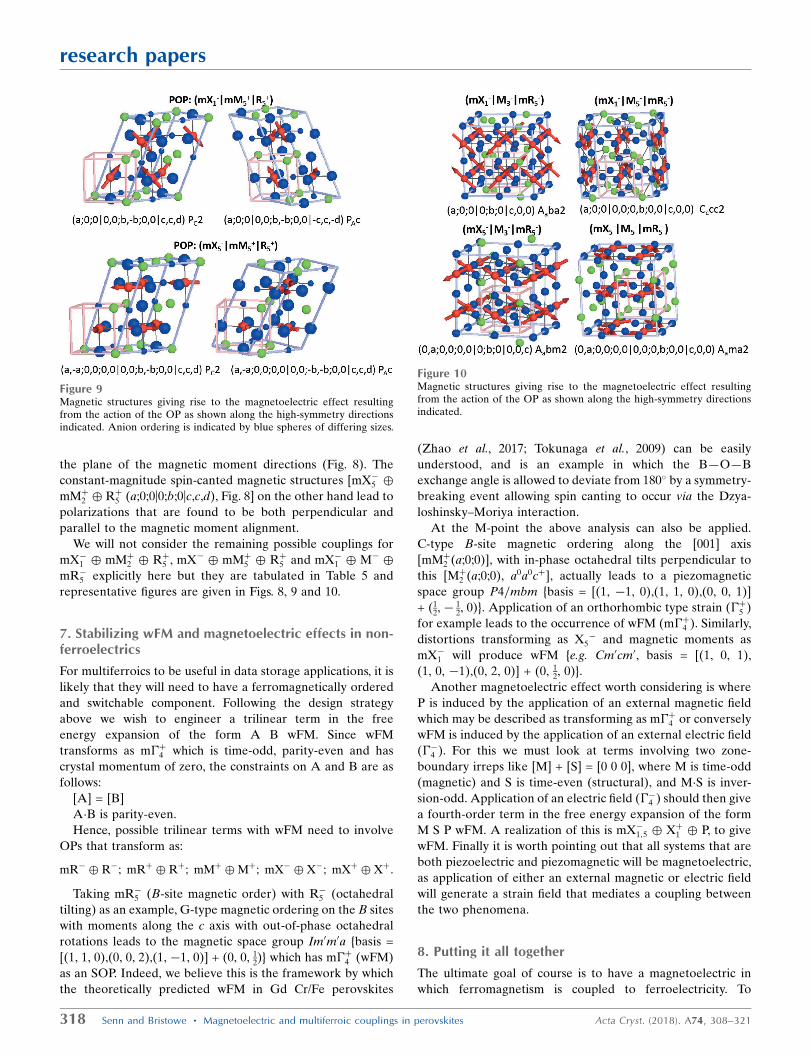
We will not consider the remaining possible couplings for
mX�1 � mMþ2 � Rþ5 , mX� � mMþ5 � Rþ5 and mX�1 � M� �
mR�5 explicitly here but they are tabulated in Table 5 and
representative figures are given in Figs. 8, 9 and 10.
7. Stabilizing wFM and magnetoelectric effects in non-ferroelectrics
For multiferroics to be useful in data storage applications, it is
likely that they will need to have a ferromagnetically ordered
and switchable component. Following the design strategy
above we wish to engineer a trilinear term in the free
energy expansion of the form A B wFM. Since wFM
transforms as m�þ4 which is time-odd, parity-even and has
crystal momentum of zero, the constraints on A and B are as
follows:
[A] = [B]
A�B is parity-even.
Hence, possible trilinear terms with wFM need to involve
OPs that transform as:
mR� � R�; mRþ � Rþ; mMþ �Mþ; mX� � X�; mXþ � Xþ:
Taking mR�5 (B-site magnetic order) with R�5 (octahedral
tilting) as an example, G-type magnetic ordering on the B sites
with moments along the c axis with out-of-phase octahedral
rotations leads to the magnetic space group Im0m0a {basis =
[(1, 1, 0),(0, 0, 2),(1, �1, 0)] + (0, 0, 12)} which has m�þ4 (wFM)
as an SOP. Indeed, we believe this is the framework by which
the theoretically predicted wFM in Gd Cr/Fe perovskites
(Zhao et al., 2017; Tokunaga et al., 2009) can be easily
understood, and is an example in which the B—O—B
exchange angle is allowed to deviate from 180� by a symmetry-
breaking event allowing spin canting to occur via the Dzya-
loshinsky–Moriya interaction.
At the M-point the above analysis can also be applied.
C-type B-site magnetic ordering along the [001] axis
[mMþ2 (a;0;0)], with in-phase octahedral tilts perpendicular to
this [Mþ2 (a;0;0), a0a0cþ], actually leads to a piezomagnetic
space group P4=mbm {basis = [(1, �1, 0),(1, 1, 0),(0, 0, 1)]
+ (12, �
12, 0)}. Application of an orthorhombic type strain (�þ5 )
for example leads to the occurrence of wFM (m�þ4 ). Similarly,
distortions transforming as X5� and magnetic moments as
mX�1 will produce wFM {e.g. Cm0cm0, basis = [(1, 0, 1),
(1, 0, �1),(0, 2, 0)] + (0, 12, 0)}.
Another magnetoelectric effect worth considering is where
P is induced by the application of an external magnetic field
which may be described as transforming as m�þ4 or conversely
wFM is induced by the application of an external electric field
(��4 ). For this we must look at terms involving two zone-
boundary irreps like [M] + [S] = [0 0 0], where M is time-odd
(magnetic) and S is time-even (structural), and M�S is inver-
sion-odd. Application of an electric field (��4 ) should then give
a fourth-order term in the free energy expansion of the form
M S P wFM. A realization of this is mX�1;5 � Xþ1 � P, to give
wFM. Finally it is worth pointing out that all systems that are
both piezoelectric and piezomagnetic will be magnetoelectric,
as application of either an external magnetic or electric field
will generate a strain field that mediates a coupling between
the two phenomena.
8. Putting it all together
The ultimate goal of course is to have a magnetoelectric in
which ferromagnetism is coupled to ferroelectricity. To
318 Senn and Bristowe � Magnetoelectric and multiferroic couplings in perovskites Acta Cryst. (2018). A74, 308–321
research papers
Figure 9Magnetic structures giving rise to the magnetoelectric effect resultingfrom the action of the OP as shown along the high-symmetry directionsindicated. Anion ordering is indicated by blue spheres of differing sizes.
Figure 10Magnetic structures giving rise to the magnetoelectric effect resultingfrom the action of the OP as shown along the high-symmetry directionsindicated.

achieve the strongest such coupling, we envisage first a
scenario with two trilinear terms in P and wFM, with one co-
dependent OP (see Fig. 11). For example: (i) Xþ1 � X�5 � P
with mX�1 � X�5 � wFM. Assuming Xþ1 represents cation
order and may not be reversed, then the reversal of the sign of
P would necessitate a reversal of X�5 . This, in turn, would
necessitate a switching of the magnetic structure which most
likely would proceed via a reversal of the direction of the
wFM. (ii) M�5 �Mþ2 � P and mM�5 �Mþ2 � wFM. Taking M�5as anion ordering, then a reversal of P would proceed via
reversal of the octahedral rotations (Mþ2 ) necessitating a
reversal of either mM�5 or wFM, the latter being more likely.
(iii) Rþ1 �R�2 � P and mR�5 �R�2 � wFM, taking Rþ1 as A-site
rocksalt cation ordering, a reversal of P would imply a
switching of R�2 which could represent B-site charge ordering
In fact, if one has an AA0 layered double perovskite (Xþ1 )
with the common Mþ2 and R�5 tilt pattern (Pnma like) no
matter if you have C (mMþ5 ), G (mR�5 ) or A (mX�1 ) magnetic
ordering (provided the spins are along certain directions), the
ground state is ferroelectric and ferromagnetic with an
indirect coupling between them. Efforts should hence be
focused on preparing A+ A03þ and A2+ A04þ layered double
perovskites with Mn4+ and Fe3+ on the B site, respectively, to
achieve the strongest wFM moments and highest ordering
temperatures.
Another scheme involving fourth-order couplings gives a
greater degree of flexibility. Similar to the above, the idea here
is to construct fourth-order terms with wFM (m�þ4 ) in. As
many of the OPs featuring in the wFM term at the fourth
order should also feature in the fourth-order term in P. Fig. 12
envisages one such possible coupling scheme by which an
extra degree of freedom related to breaking structural
symmetry (S2) is introduced to the magnetoelectric couplings
discussed above, and is equivalent to using antisymmetric
(DM) arguments to design wFM. The figure shows that it is
possible to construct fourth-order terms with at least two OPs
in common in both P and wFM terms, i.e. M1 M2 S1 P and M1
S1 S2 wFM. Each fourth-order term must individually conserve
crystal momentum, time reversal and inversion symmetry.
Hence the polar part, M1 M2 S1, can be selected according to
the analysis in the previous section, leaving the wFM part, M1
S1 S2, to be decided on. Since M1 S1 are fixed by the polar part,
the only decision to be made is the nature of S2. We require
that the crystal momentum of [S2] equals the sum of the crystal
momentum [M1] + [S1], and that parity with respect to inver-
sion is equal to the product of the parity of M1�S1 (i.e. opposite
to that of M2). For example, with mMþ2;5 (M), mR�5 (M) and Xþ1(S1), S2 must be either Rþ1;5 or M�2;3;5.
Finally, we note that if one predisposes the system to certain
distortions, which are implied as SOPs in the above analysis,
certain phases may be thermodynamically favoured over
others. This is an important part of controlling the relative
OPDs which ultimately affect the higher-order couplings that
drive magnetoelectric properties. We discuss now a few of the
most promising candidates and propose some design strategies
based on SOP analysis. SOPs are listed in Tables 3, 4 and 5 for
some fourth-order couplings in ferroelectric polarization. Any
further distortion to the Pm�33m aristotype that the system is
predisposed to, which transforms as irreps in this list, will act
to stabilize one particular OPD over another. Or, put another
way, at the harmonic order (quadratic phonon modes) all
possible OPDs are degenerate in energy.
The most obvious strategy is to pre-strain (transforming as
�þ3;5) the system through epitaxial growth. Another strategy is
to search through tables, such as Tables 3, 4 and 5, to find
irreps that correspond to the most commonly observed
distortions in the perovskite phase, such as the octahedral
rotations (Mþ2 and R�5 ), Jahn–Teller distortions in systems with
a degeneracy in their d orbitals or indeed polar distortions
themselves in d0 systems. In the ‘undistorted’ perovskite
structure these will correspond to the lowest-lying phonon
modes (rigid unit modes in the cases of the octahedral rota-
tion). Any energy penalty paid at the quadratic order will be
kept low with respect to the trilinear terms that always act to
lower the free energy, and therefore will drive a phase tran-
sition. For example, for Xþ1 � mMþ2 � mR�5 , SOPs are strain,
��5 , and X-point distortions. The OP(a;0;0j0;b;0jc,c,0) PAmc21
is the most promising candidate, as the only SOP is antipolar
X5� distortions. Therefore, in addition to striped cation
ordering, cations which are susceptible to off-centre distor-
tions should be chosen. For mX�1 � M�5 � mR�5 or mX�1 �
mMþ2 � Rþ5 , B sites with a propensity to undergo charge (Mþ4or R�2 ) and orbital order (Mþ3 or R�3 ) should be chosen. A
similar design strategy of selecting a system which is predis-
posed to certain SOPs may be adopted for stabilizing wFM.
9. Conclusion
Using group-theoretical means, we have enumerated the
possible magnetoelectric couplings in the perovskite structure
with respect to its aristotypical symmetry Pm�33m. Our
research papers
Acta Cryst. (2018). A74, 308–321 Senn and Bristowe � Magnetoelectric and multiferroic couplings in perovskites 319
Figure 11A scheme for including third-order coupling terms in the free energyexpansion involving the OP related to weak ferromagnetic spin cantingand ferroelectric polarization.
Figure 12A scheme for including fourth-order coupling terms in the free energyexpansion involving the OP related to weak ferromagnetic spin cantingand ferroelectric polarization.

enumeration is complete up to the third-order terms for zone-
boundary magnetic structures, and for fourth-order terms for
B-site magnetism only. Our results show that, for zone-
boundary magnetic ordering, only magnetism on both A and B
sites transforming either both as X-point or R-point irreps can
produce a magnetoelectric coupling at the third order, which is
illustrated with first-principles calculations. For magnetism on
the B site alone, then only fourth-order terms can produce the
desired effect. We propose a design strategy based on POPs
consisting of a superposition of three irreps, one each from the
X-, M- and R-points, chosen in such a way that crystal
momentum is conserved, that two are time-odd and either one
or all are inversion-odd. These ideas are extended to a design
strategy for weak ferromagnetism, which may then be coupled
to the ferroelectric polarization in a similar manner to the
recently much discussed hybrid improper ferroelectric
Ca3Mn2O7. Without a doubt, predicting and controlling
physical properties arising from magnetic order will remain a
challenging area for many years to come. However, our
systematic enumeration of coupling mechanisms along with
secondary order parameters at least provides some direction
for how this might ultimately be achieved.
APPENDIX ANotation used in order parameter directions
We will be forming OPs from up to three different zone-
boundary irreps, which we will denote by using the symbol for
direct sum ‘�’, for example Mþ2 � R�5 represents an OP that
has atomic displacements that transform as both irreps. By
forming this OP we will effectively be conducting a thought
experiment as to what would happen if the parent Pm�33m
became spontaneously unstable with respect to atomic
displacements (in this case octahedral rotations) transforming
as these irreps. However, specifying these irreps alone does
not capture how the displacements (or magnetic orderings)
combine with respect to each other, and hence the associated
isotropy subgroup. To do this we need to describe the full
OPD of the OP transforming as the specified irreps and we
follow the notation used in ISODISRORT (Campbell et al.,
2006). For Mþ2 � R�5 , an OPD is OP(a;0;0jb,0,0), where ‘j’
denotes a division between the OPD parts belonging to Mþ2and R�5 , respectively. Semi-colons ‘;’ denote divisions between
different OPDs resulting from the degeneracy of the propa-
gation vector in Pm�33m. At the M-point the possible k-actives
are (12,
12, 0);(1
2, 0, 12);(0, 1
2,12), where the order respects the order
of appearance in the OPD. Similarly, for an OP transforming
as X-point irreps we will need to specify which k-actives of
(0, 12, 0);(1
2, 0, 0);(0, 0, 12) are in use. In general we will only form
OPs from one k-active per irrep (equivalent to using the small
irrep only). However, the notation we give will always reflect
the total number of possible k-actives. At the R-point there is
only one possible k-active, but in this case the irrep is multi-
dimensional and, as in the case of ��4 , this is specified through
use of commas between the letters. The total dimension of the
OP is hence a function of the number of superposed irreps, the
degeneracy of the propagation vectors associated with any of
the irreps and the dimensionality of the small irreps them-
selves. All need to be fully specified along with the setting and
space group of the parent structure to uniquely identify the
isotropy subgroup.
Acknowledgements
MSS would like to acknowledge Miss Hanna Bostrom and Dr
Angel Arevalo-Lopez for useful discussions. Calculations
were performed on the Imperial College London high-
performance computing facility.
Funding information
MSS acknowledges the Royal Commission for the Exhibition
of 1851 and the Royal Society for fellowships. NCB also
acknowledges the Royal Commission for the Exhibition of
1851 for a fellowship and is also supported by an Imperial
College Research Fellowship and a Royal Society research
grant. We are also grateful to the UK Materials and Molecular
Modelling Hub for computational resources, which is partially
funded by EPSRC (EP/P020194/1).
References
Aimi, A., Mori, D., Hiraki, K., Takahashi, T., Shan, Y. J., Shirako, Y.,Zhou, J. & Inaguma, Y. (2014). Chem. Mater. 26, 2601–2608.
Aleksandrov, K. S. & Bartolome, J. (1994). J. Phys. Condens. Matter,6, 8219–8235.
Aroyo, M. I., Kirov, A., Capillas, C., Perez-Mato, J. M. &Wondratschek, H. (2006). Acta Cryst. A62, 115–128.
Benedek, N. A. & Fennie, C. J. (2011). Phys. Rev. Lett. 106, 107204.Benedek, N. A., Rondinelli, J. M., Djani, H., Ghosez, P. & Lightfoot,
P. (2015). Dalton Trans. 44, 10543–10558.Bostrom, H. L. B., Senn, M. S. & Goodwin, A. L. (2018). Nat.
Commun. 9, 2380.Bousquet, E., Dawber, M., Stucki, N., Lichtensteiger, C., Hermet, P.,
Gariglio, S., Triscone, J.-M. & Ghosez, P. (2008). Nature, 452, 732–736.
Bradley, C. J. C. J. & Cracknell, A. P. (1972). The MathematicalTheory of Symmetry in Solids: Representation Theory for PointGroups and Space Groups. Oxford: Clarendon Press.
Bristowe, N. C., Varignon, J., Fontaine, D., Bousquet, E. & Ghosez, P.(2015). Nat. Commun. 6, 6677.
Campbell, B. J., Evans, J. S. O., Perselli, F. & Stokes, H. T. (2007). IUCrComput. Commun. Newsl. 8, 81–95.
Campbell, B. J., Stokes, H. T., Tanner, D. E. & Hatch, D. M. (2006). J.Appl. Cryst. 39, 607–614.
Castillo-Martınez, E., Williams, A. J. & Attfield, J. P. (2006). J. SolidState Chem. 179, 3505–3510.
Chen, W.-T., Wang, C.-W., Wu, H.-C., Chou, F.-C., Yang, H.-D.,Simonov, A. & Senn, M. S. (2018). Phys. Rev. B, 97, 144102.
Dzyaloshinsky, I. (1958). J. Phys. Chem. Solids, 4, 241–255.Fox, D. L., Tilley, D. R., Scott, J. F. & Guggenheim, H. J. (1980). Phys.
Rev. B, 21, 2926–2936.Fukushima, T., Stroppa, A., Picozzi, S. & Perez-Mato, J. M. (2011).
Phys. Chem. Chem. Phys. 13, 12186–12190.Giovannetti, G., Kumar, S., van den Brink, J. & Picozzi, S. (2009).
Phys. Rev. Lett. 103, 037601.Glazer, A. M. (1972). Acta Cryst. B28, 3384–3392.Hatch, D. & Stokes, H. (1987). Phys. Rev. B, 35, 8509–8516.Hatch, D. M. & Stokes, H. T. (2003). J. Appl. Cryst. 36, 951–952.Hatch, D. M., Stokes, H. T., Aleksandrov, K. S. & Misyul, S. V. (1989).
Phys. Rev. B, 39, 9282–9288.
320 Senn and Bristowe � Magnetoelectric and multiferroic couplings in perovskites Acta Cryst. (2018). A74, 308–321
research papers

Howard, C. J. & Carpenter, M. A. (2010). Acta Cryst. B66, 40–50.
Howard, C. J. & Stokes, H. T. (1998). Acta Cryst. B54, 782–789.Howard, C. J. & Stokes, H. T. (2005). Acta Cryst. A61, 93–111.Karen, P., Woodward, P. M., Linden, J., Vogt, T., Studer, A. & Fischer,
P. (2001). Phys. Rev. B, 64, 214405.Khalyavin, D. D., Salak, A. N., Manuel, P., Olekhnovich, N. M.,
Pushkarev, A. V., Radysh, Y. V., Fedorchenko, A. V., Fertman, E. L.,Desnenko, V. A. & Ferreira, M. G. S. (2015). Z. Kristallogr. 230,767–774.
King, G. & Woodward, P. M. (2010). J. Mater. Chem. 20, 5785.Knight, K. S. (2009). Can. Mineral. 47, 381–400.Kovalev, O. V. (1993). Representations of the Crystallographic Space
Groups: Irreducible Representations, Induced Representations, andCorepresentations. Philadelphia: Gordon and Breach Science.
Kresse, G. & Furthmuller, J. (1996). Comput. Mater. Sci. 6, 15–50.Kresse, G. & Hafner, J. (1993). Phys. Rev. B, 47, 558–561.Levanyuk, A. P. & Sannikov, D. G. (1974). Sov. Phys. Usp. 17, 199–
214.Liechtenstein, A., Anisimov, V. & Zaanen, J. (1995). Phys. Rev. B, 52,
R5467–R5470.Markkula, M., Arevalo-Lopez, A. M., Kusmartseva, A., Rodgers,
J. A., Ritter, C., Wu, H. & Atteld, J. P. (2011). Phys. Rev. B, 84, 1–5.Miller, S. C. & Love, W. F. (1967). Tables of Irreducible Representa-
tions of Space Groups and Co-Representations of Magnetic SpaceGroups. Boulder: Pruett.
Moriya, T. (1960). Phys. Rev. 120, 91–98.Mulder, A. T., Benedek, N. A., Rondinelli, J. M. & Fennie, C. J.
(2013). Adv. Funct. Mater. 23, 4810–4820.Orobengoa, D., Capillas, C., Aroyo, M. I. & Perez-Mato, J. M. (2009).
J. Appl. Cryst. 42, 820–833.Perdew, J. P., Ruzsinszky, A., Csonka, G. I., Vydrov, O. A., Scuseria,
G. E., Constantin, L. A., Zhou, X. & Burke, K. (2008). Phys. Rev.Lett. 100, 136406.
Perez-Mato, J. M., Orobengoa, D. & Aroyo, M. I. (2010). Acta Cryst.A66, 558–590.
Perez-Mato, J. M., Ribeiro, J. L., Petricek, V. & Aroyo, M. I. (2012). J.Phys. Condens. Matter, 24, 163201.
Rodriguez, E. E., Proffen, Th., Llobet, A., Rhyne, J. J. & Mitchell, J. F.(2005). Phys. Rev. B, 71, 104430.
Rondinelli, J. M. & Fennie, C. J. (2012). Adv. Mater. 24, 1961–1968.
Saxena, A., Barsch, G. R. & Hatch, D. M. (1994). Phase Transitions,46, 89–142.
Stokes, H. T. & Campbell, B. J. (2017). Acta Cryst. A73, 4–13.Stokes, H. T., Campbell, B. J. & Cordes, R. (2013). Acta Cryst. A69,
388–395.Stokes, H. T. & Hatch, D. M. (1988). Isotropy Subgroups of the 230
Crystallographic Space Groups. Singapore: World Scientific.Stokes, H. T. & Hatch, D. M. (1991). Phase Transitions, 34, 53–67.Stokes, H. T., Kisi, E. H., Hatch, D. M. & Howard, C. J. (2002). Acta
Cryst. B58, 934–938.Talanov, M. V., Shirokov, V. B. & Talanov, V. M. (2016). Acta Cryst.
A72, 222–235.Tokunaga, Y., Furukawa, N., Sakai, H., Taguchi, Y., Arima, T. H. &
Tokura, Y. (2009). Nat. Mater. 8, 558–562.Varignon, J., Bristowe, N. C., Bousquet, E. & Ghosez, P. (2015a). Sci.
Rep. 5, 15364.Varignon, J., Bristowe, N. C., Bousquet, E. & Ghosez, P. (2015b). C. R.
Phys. 16, 153–167.Varignon, J., Bristowe, N. C. & Ghosez, P. (2016). Phys. Rev. Lett. 116,
057602.Vogt, T., Woodward, P. M., Karen, P., Hunter, B. A., Henning, P. &
Moodenbaugh, A. R. (2000). Phys. Rev. Lett. 84, 2969–2972.Wang, X. et al. (2015). Phys. Rev. Lett. 115, 087601.Yamauchi, K. (2013). J. Phys. Soc. Jpn, 82, 043702.Yang, Y., Iniguez, J., Mao, A. J. & Bellaiche, L. (2014). Phys. Rev. Lett.
112, 057202.Yang, M., Oro-Sole, J., Rodgers, J. A., Jorge, A. B., Fuertes, A. &
Attfield, J. P. (2011). Nat. Chem. 3, 47–52.Yang, Y., Ren, W., Stengel, M., Yan, X. H. & Bellaiche, L. (2012).
Phys. Rev. Lett. 109, 057602.Young, J. & Rondinelli, J. M. (2013). Chem. Mater. 25, 4545–4550.Young, J., Stroppa, A., Picozzi, S. & Rondinelli, J. M. (2015). J. Phys.
Condens. Matter, 27, 283202.Zhao, H. J., Bellaiche, L., Chen, X. M. & Iniguez, J. (2017). Nat.
Commun. 8, 14025.Zhou, Q. & Rabe, K. M. (2013). arXiv:1306.1839.Zuo, P., Colin, C. V., Klein, H., Bordet, P., Suard, E., Elkaim, E. &
Darie, C. (2017). Inorg. Chem. 56, 8478–8489.
research papers
Acta Cryst. (2018). A74, 308–321 Senn and Bristowe � Magnetoelectric and multiferroic couplings in perovskites 321