Embed Size (px)
Citation preview

A Guide to
Thermal Analysis
This guide starts from applications of thermal analysis and its role in simulation driven design. Fundamental concepts and principles will be introduced such as conduction, convection, radiation, linear and nonlinear heat transfer, steady state and transient analysis, etc. Finally we will discuss how to choose appropriate finite element analysis software for thermal analysis; and introduce strength of midas NFX for solving thermal problems.
Page 3
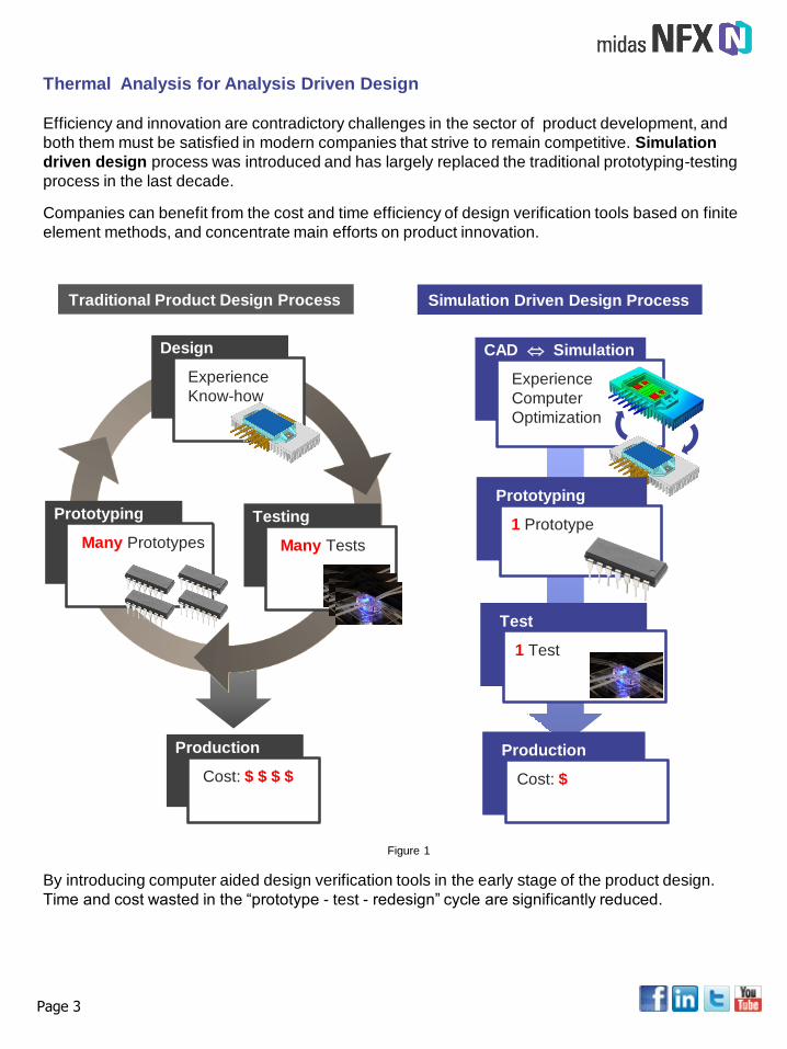
Efficiency and innovation are contradictory challenges in the sector of product development, and
both them must be satisfied in modern companies that strive to remain competitive. Simulation
driven design process was introduced and has largely replaced the traditional prototyping-testing
process in the last decade.
Companies can benefit from the cost and time efficiency of design verification tools based on finite
element methods, and concentrate main efforts on product innovation.
Design
Experience
Know-how
Prototyping
Many Prototypes
Production
Cost: $ $ $ $
Traditional Product Design Process Simulation Driven Design Process
CAD Simulation
Experience
Computer
Optimization
Prototyping
1 PrototypeTesting
Many Tests
Test
1 Test
Production
Cost: $
Thermal Analysis for Analysis Driven Design
By introducing computer aided design verification tools in the early stage of the product design.
Time and cost wasted in the “prototype - test - redesign” cycle are significantly reduced.
Figure 1
Page 3
Thermal related problems are challenges commonly faced by product design engineers. Some of
the problems include overheating, excessive thermal stresses, thermal effect on dimensional
stability, etc. Following are some applications in which thermal factors need to be considered.
Thermal Analysis Application
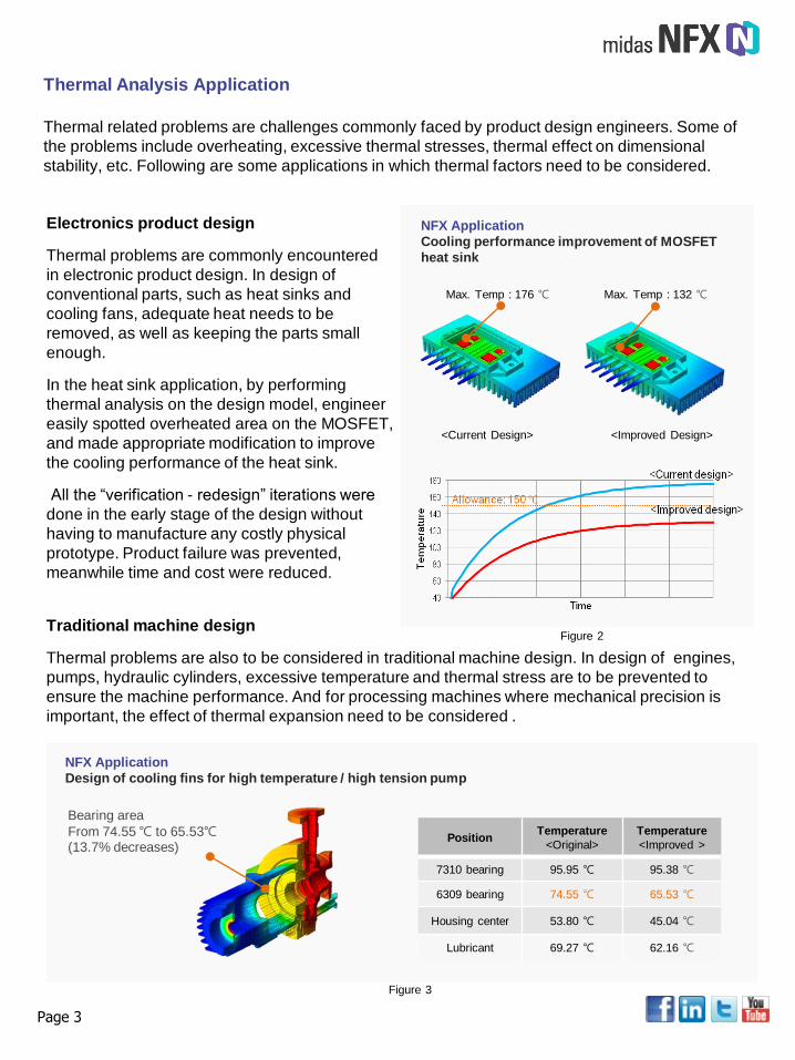
Electronics product design
Thermal problems are commonly encountered
in electronic product design. In design of
conventional parts, such as heat sinks and
cooling fans, adequate heat needs to be
removed, as well as keeping the parts small
enough.
In the heat sink application, by performing
thermal analysis on the design model, engineer
easily spotted overheated area on the MOSFET,
and made appropriate modification to improve
the cooling performance of the heat sink.
All the “verification - redesign” iterations were
done in the early stage of the design without
having to manufacture any costly physical
prototype. Product failure was prevented,
meanwhile time and cost were reduced.
Max. Temp : 176 ℃ Max. Temp : 132 ℃
<Current Design> <Improved Design>
NFX Application
Cooling performance improvement of MOSFET
heat sink
Traditional machine design
Thermal problems are also to be considered in traditional machine design. In design of engines,
pumps, hydraulic cylinders, excessive temperature and thermal stress are to be prevented to
ensure the machine performance. And for processing machines where mechanical precision is
important, the effect of thermal expansion need to be considered .
PositionTemperature
<Original>
Temperature
<Improved >
7310 bearing 95.95 ℃ 95.38 ℃
6309 bearing 74.55 ℃ 65.53 ℃
Housing center 53.80 ℃ 45.04 ℃
Lubricant 69.27 ℃ 62.16 ℃
Bearing area
From 74.55 ℃ to 65.53℃(13.7% decreases)
NFX Application
Design of cooling fins for high temperature / high tension pump
Figure 2
Figure 3
In the application above, cooling fins were designed to prevent overheating of a pump which
operates under high temperature and high pressure environment.
Page 3
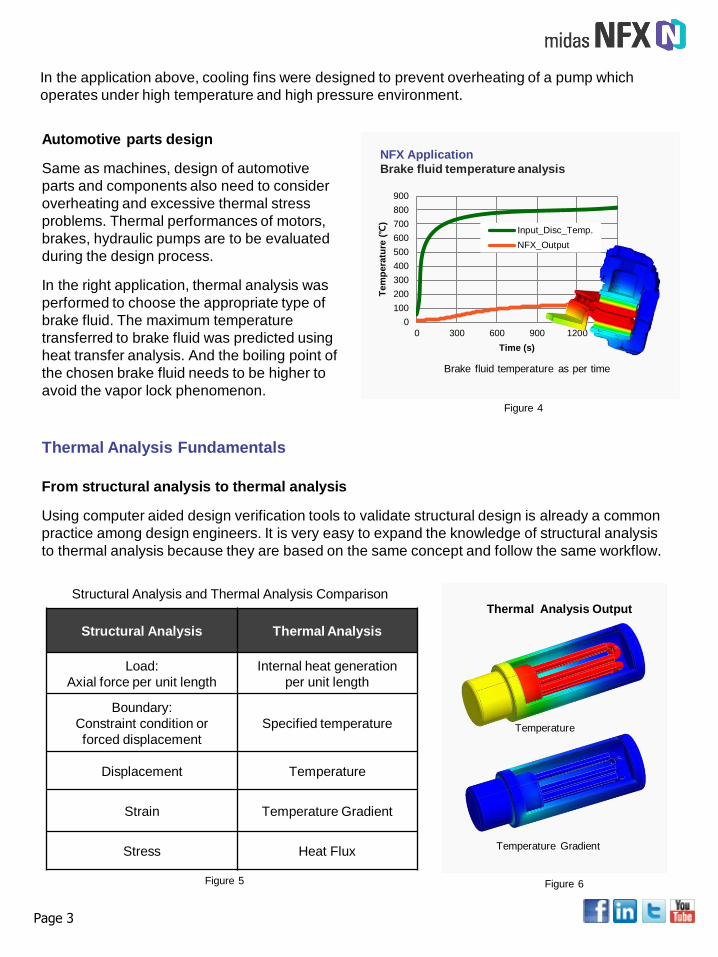
Automotive parts design
Same as machines, design of automotive
parts and components also need to consider
overheating and excessive thermal stress
problems. Thermal performances of motors,
brakes, hydraulic pumps are to be evaluated
during the design process.
In the right application, thermal analysis was
performed to choose the appropriate type of
brake fluid. The maximum temperature
transferred to brake fluid was predicted using
heat transfer analysis. And the boiling point of
the chosen brake fluid needs to be higher to
avoid the vapor lock phenomenon.
0
100
200
300
400
500
600
700
800
900
0 300 600 900 1200 1500
Tem
pera
ture
(℃
)
Time (s)
Input_Disc_Temp.
NFX_Output
Brake fluid temperature as per time
NFX Application
Brake fluid temperature analysis
From structural analysis to thermal analysis
Using computer aided design verification tools to validate structural design is already a common
practice among design engineers. It is very easy to expand the knowledge of structural analysis
to thermal analysis because they are based on the same concept and follow the same workflow.
Thermal Analysis Fundamentals
Structural Analysis Thermal Analysis
Load:
Axial force per unit length
Internal heat generation
per unit length
Boundary:
Constraint condition or
forced displacement
Specified temperature
Displacement Temperature
Strain Temperature Gradient
Stress Heat Flux
Temperature
Temperature Gradient
Structural Analysis and Thermal Analysis Comparison
Figure 4
Figure 5 Figure 6
Thermal Analysis Output
As illustrated in figure 5 - 6, thermal analysis are usually performed to find the temperature
distribution, temperature gradient and heat flux of the target model. The simulation approach is
particularly beneficial for solving thermal problems because firstly you can use the same CAD
model to perform thermal analysis as well as structural analysis. Secondly measuring
temperatures and temperature changes can be very difficult in a real test, especially when
temperatures inside small parts and assemblies are to be decided.
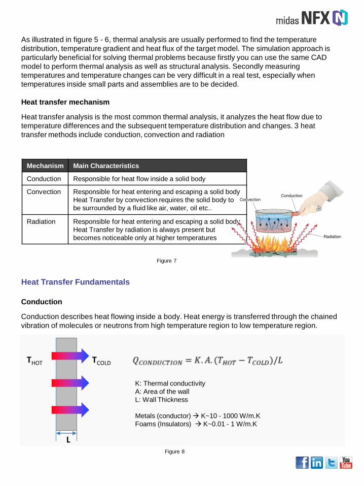
Heat transfer mechanism
Heat transfer analysis is the most common thermal analysis, it analyzes the heat flow due to
temperature differences and the subsequent temperature distribution and changes. 3 heat
transfer methods include conduction, convection and radiation
Mechanism Main Characteristics
Conduction Responsible for heat flow inside a solid body
Convection Responsible for heat entering and escaping a solid body
Heat Transfer by convection requires the solid body to
be surrounded by a fluid like air, water, oil etc..
Radiation Responsible for heat entering and escaping a solid body
Heat Transfer by radiation is always present but
becomes noticeable only at higher temperatures
Figure 7
Conduction
Conduction describes heat flowing inside a body. Heat energy is transferred through the chained
vibration of molecules or neutrons from high temperature region to low temperature region.
Heat Transfer Fundamentals
THOT TCOLD
L
K: Thermal conductivity
A: Area of the wall
L: Wall Thickness
Metals (conductor) K~10 - 1000 W/m.K
Foams (Insulators) K~0.01 - 1 W/m.K
Figure 8
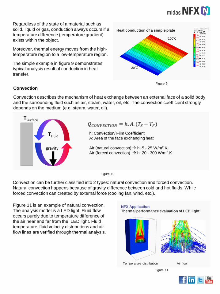
Regardless of the state of a material such as
solid, liquid or gas, conduction always occurs if a
temperature difference (temperature gradient)
exists within the object.
Moreover, thermal energy moves from the high-
temperature region to a low-temperature region.
The simple example in figure 9 demonstrates
typical analysis result of conduction in heat
transfer.
Heat conduction of a simple plate
Figure 9
100℃
20℃
Convection
Convection describes the mechanism of heat exchange between an external face of a solid body
and the surrounding fluid such as air, steam, water, oil, etc. The convection coefficient strongly
depends on the medium (e.g. steam, water, oil).
gravity
TSurface
TFluidh: Convection/ Film Coefficient
A: Area of the face exchanging heat
Air (natural convection) h~5 - 25 W/m2.K
Air (forced convection) h~20 - 300 W/m2.K
Figure 10
Convection can be further classified into 2 types: natural convection and forced convection.
Natural convection happens because of gravity difference between cold and hot fluids. While
forced convection can created by external force (cooling fan, wind, etc.).
Figure 11 is an example of natural convection.
The analysis model is a LED light. Fluid flow
occurs purely due to temperature difference of
the air near and far from the LED light. Fluid
temperature, fluid velocity distributions and air
flow lines are verified through thermal analysis.
NFX Application
Thermal performance evaluation of LED light
Temperature distribution Air flow
Figure 11
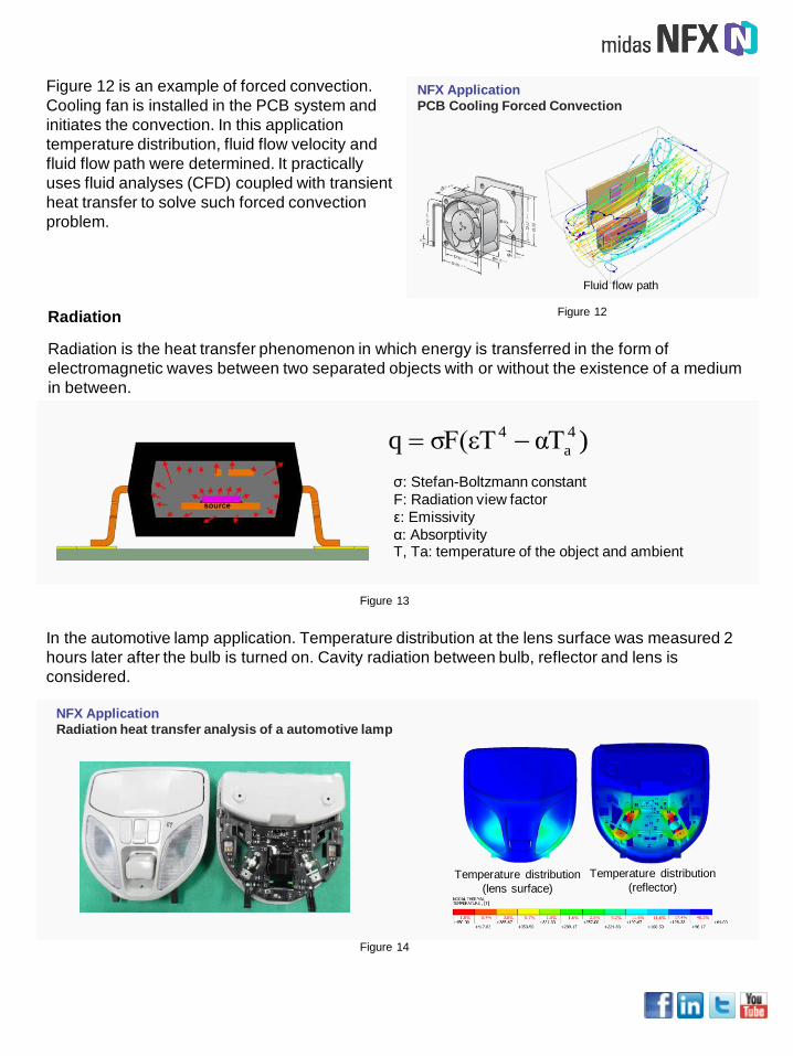
Figure 12 is an example of forced convection.
Cooling fan is installed in the PCB system and
initiates the convection. In this application
temperature distribution, fluid flow velocity and
fluid flow path were determined. It practically
uses fluid analyses (CFD) coupled with transient
heat transfer to solve such forced convection
problem.
Radiation
Radiation is the heat transfer phenomenon in which energy is transferred in the form of
electromagnetic waves between two separated objects with or without the existence of a medium
in between.
NFX Application
PCB Cooling Forced Convection
Figure 12
Fluid flow path
)αTσF(εTq 4
a
4
σ: Stefan-Boltzmann constant
F: Radiation view factor
ε: Emissivity
α: AbsorptivityT, Ta: temperature of the object and ambient
Figure 13
In the automotive lamp application. Temperature distribution at the lens surface was measured 2
hours later after the bulb is turned on. Cavity radiation between bulb, reflector and lens is
considered.
NFX Application
Radiation heat transfer analysis of a automotive lamp
Temperature distribution
(lens surface)
Temperature distribution
(reflector)
Figure 14
Linear and nonlinear heat transfer
Heat transfer analysis can also be classified as linear and nonlinear considering material
properties, heat transfer mechanisms and analysis conditions.
For linear heat transfer analysis, material properties are assumed to be constant and do not vary
according to temperature. However, most materials, especially metallic materials, have
properties (conductivity, specific heat, and density) that are temperature-dependent. Therefore,
when modeling and simulating temperature distribution for such materials, nonlinearities have to
be accounted.
For conduction and convection heat transfer, heat flux has linear relationship with temperature
difference. (see Figure 8, 10) However radiation heat transfer is a high order nonlinear
phenomenon due to T4 and Ta4 terms in the governing equation. (see Figure 13) Therefore,
nonlinear analysis is needed in radiation problems.
In addition, linear analysis consider loads and boundaries to be constant ( constant temperature
of heat source and environment). This may involve some assumptions and hypotheses.
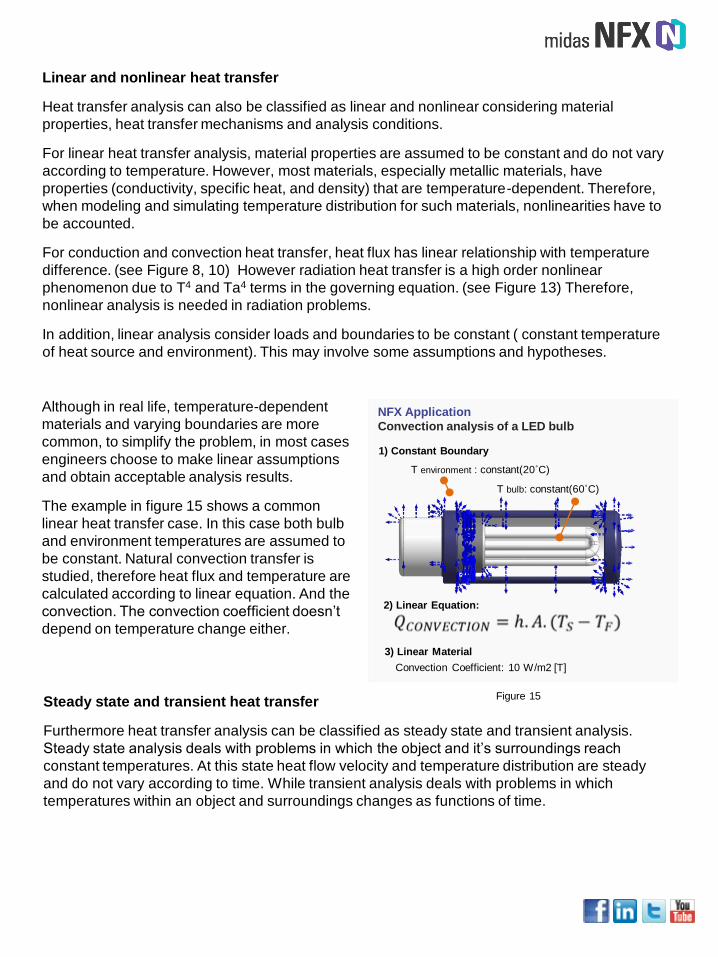
Although in real life, temperature-dependent
materials and varying boundaries are more
common, to simplify the problem, in most cases
engineers choose to make linear assumptions
and obtain acceptable analysis results.
The example in figure 15 shows a common
linear heat transfer case. In this case both bulb
and environment temperatures are assumed to
be constant. Natural convection transfer is
studied, therefore heat flux and temperature are
calculated according to linear equation. And the
convection. The convection coefficient doesn’t
depend on temperature change either.
NFX Application
Convection analysis of a LED bulb
T bulb: constant(60˚C)
T environment : constant(20˚C)
2) Linear Equation:
Convection Coefficient: 10 W/m2 [T]
1) Constant Boundary
3) Linear Material
Figure 15Steady state and transient heat transfer
Furthermore heat transfer analysis can be classified as steady state and transient analysis.
Steady state analysis deals with problems in which the object and it’s surroundings reach
constant temperatures. At this state heat flow velocity and temperature distribution are steady
and do not vary according to time. While transient analysis deals with problems in which
temperatures within an object and surroundings changes as functions of time.
Steady-stateTransient
Time
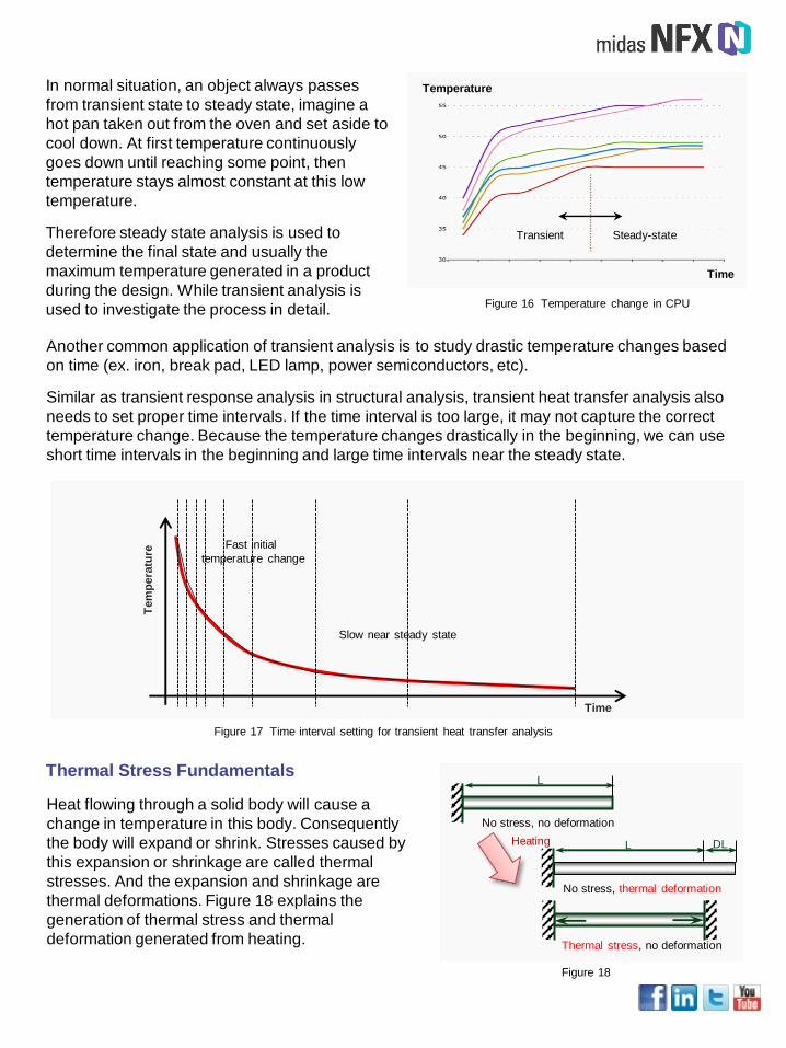
TemperatureIn normal situation, an object always passes
from transient state to steady state, imagine a
hot pan taken out from the oven and set aside to
cool down. At first temperature continuously
goes down until reaching some point, then
temperature stays almost constant at this low
temperature.
Therefore steady state analysis is used to
determine the final state and usually the
maximum temperature generated in a product
during the design. While transient analysis is
used to investigate the process in detail. Figure 16 Temperature change in CPU
Another common application of transient analysis is to study drastic temperature changes based
on time (ex. iron, break pad, LED lamp, power semiconductors, etc).
Similar as transient response analysis in structural analysis, transient heat transfer analysis also
needs to set proper time intervals. If the time interval is too large, it may not capture the correct
temperature change. Because the temperature changes drastically in the beginning, we can use
short time intervals in the beginning and large time intervals near the steady state.
Tem
pera
ture
Time
Fast initial
temperature change
Slow near steady state
Figure 17 Time interval setting for transient heat transfer analysis
Heat flowing through a solid body will cause a
change in temperature in this body. Consequently
the body will expand or shrink. Stresses caused by
this expansion or shrinkage are called thermal
stresses. And the expansion and shrinkage are
thermal deformations. Figure 18 explains the
generation of thermal stress and thermal
deformation generated from heating.
Thermal Stress Fundamentals
No stress, no deformation
L
L DL
No stress, thermal deformation
Thermal stress, no deformation
Heating
Figure 18
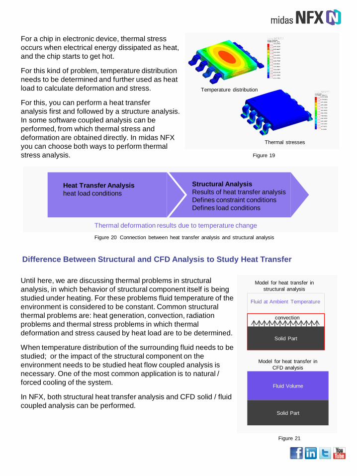
For a chip in electronic device, thermal stress
occurs when electrical energy dissipated as heat,
and the chip starts to get hot.
For this kind of problem, temperature distribution
needs to be determined and further used as heat
load to calculate deformation and stress.
For this, you can perform a heat transfer
analysis first and followed by a structure analysis.
In some software coupled analysis can be
performed, from which thermal stress and
deformation are obtained directly. In midas NFX
you can choose both ways to perform thermal
stress analysis. Figure 19
Temperature distribution
Thermal stresses
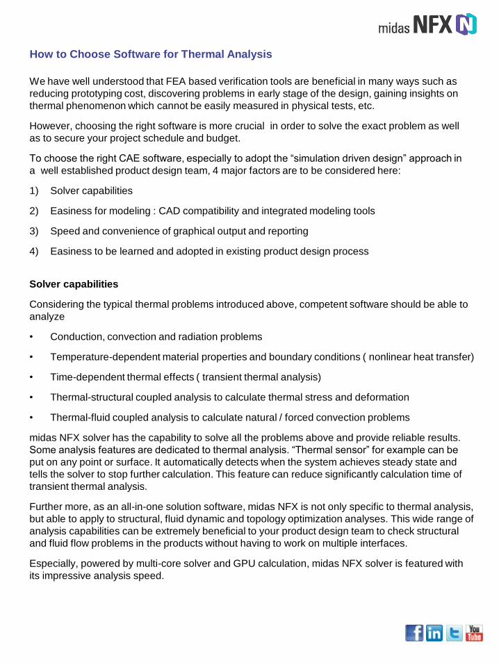
Thermal deformation results due to temperature change
Heat Transfer Analysis
heat load conditions
Structural Analysis
Results of heat transfer analysis
Defines constraint conditions
Defines load conditions
Figure 20 Connection between heat transfer analysis and structural analysis
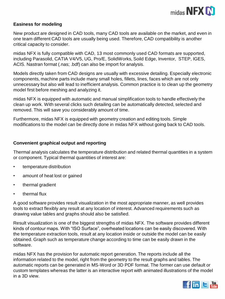
Until here, we are discussing thermal problems in structural
analysis, in which behavior of structural component itself is being
studied under heating. For these problems fluid temperature of the
environment is considered to be constant. Common structural
thermal problems are: heat generation, convection, radiation
problems and thermal stress problems in which thermal
deformation and stress caused by heat load are to be determined.
When temperature distribution of the surrounding fluid needs to be
studied; or the impact of the structural component on the
environment needs to be studied heat flow coupled analysis is
necessary. One of the most common application is to natural /
forced cooling of the system.
In NFX, both structural heat transfer analysis and CFD solid / fluid
coupled analysis can be performed.
Difference Between Structural and CFD Analysis to Study Heat Transfer
Fluid Volume
Solid Part
Model for heat transfer in
CFD analysis
Solid Part
Fluid at Ambient Temperature
convection
Model for heat transfer in
structural analysis
Figure 21
We have well understood that FEA based verification tools are beneficial in many ways such as
reducing prototyping cost, discovering problems in early stage of the design, gaining insights on
thermal phenomenon which cannot be easily measured in physical tests, etc.
However, choosing the right software is more crucial in order to solve the exact problem as well
as to secure your project schedule and budget.
To choose the right CAE software, especially to adopt the “simulation driven design” approach in
a well established product design team, 4 major factors are to be considered here:
1) Solver capabilities
2) Easiness for modeling : CAD compatibility and integrated modeling tools
3) Speed and convenience of graphical output and reporting
4) Easiness to be learned and adopted in existing product design process
How to Choose Software for Thermal Analysis
Solver capabilities
Considering the typical thermal problems introduced above, competent software should be able to
analyze
• Conduction, convection and radiation problems
• Temperature-dependent material properties and boundary conditions ( nonlinear heat transfer)
• Time-dependent thermal effects ( transient thermal analysis)
• Thermal-structural coupled analysis to calculate thermal stress and deformation
• Thermal-fluid coupled analysis to calculate natural / forced convection problems
midas NFX solver has the capability to solve all the problems above and provide reliable results.
Some analysis features are dedicated to thermal analysis. “Thermal sensor” for example can be
put on any point or surface. It automatically detects when the system achieves steady state and
tells the solver to stop further calculation. This feature can reduce significantly calculation time of
transient thermal analysis.
Further more, as an all-in-one solution software, midas NFX is not only specific to thermal analysis,
but able to apply to structural, fluid dynamic and topology optimization analyses. This wide range of
analysis capabilities can be extremely beneficial to your product design team to check structural
and fluid flow problems in the products without having to work on multiple interfaces.
Especially, powered by multi-core solver and GPU calculation, midas NFX solver is featured with
its impressive analysis speed.
Easiness for modeling
New product are designed in CAD tools, many CAD tools are available on the market, and even in
one team different CAD tools are usually being used. Therefore, CAD compatibility is another
critical capacity to consider.
midas NFX is fully compatible with CAD, 13 most commonly used CAD formats are supported,
including Parasolid, CATIA V4/V5, UG, Pro/E, SolidWorks, Soild Edge, Inventor, STEP, IGES,
ACIS. Nastran format (.nas; .bdf) can also be import for analysis.
Models directly taken from CAD designs are usually with excessive detailing. Especially electronic
components, machine parts include many small holes, fillets, lines, faces which are not only
unnecessary but also will lead to inefficient analysis. Common practice is to clean up the geometry
model first before meshing and analyzing it.
midas NFX is equipped with automatic and manual simplification tools to handle effectively the
clean up work. With several clicks such detailing can be automatically detected, selected and
removed. This will save you considerably amount of time.
Furthermore, midas NFX is equipped with geometry creation and editing tools. Simple
modifications to the model can be directly done in midas NFX without going back to CAD tools.
Convenient graphical output and reporting
Thermal analysis calculates the temperature distribution and related thermal quantities in a system
or component. Typical thermal quantities of interest are:
• temperature distribution
• amount of heat lost or gained
• thermal gradient
• thermal flux
A good software provides result visualization in the most appropriate manner, as well provides
tools to extract flexibly any result at any location of interest. Advanced requirements such as
drawing value tables and graphs should also be satisfied.
Result visualization is one of the biggest strengths of midas NFX. The software provides different
kinds of contour maps. With “ISO Surface”, overheated locations can be easily discovered. With
the temperature extraction tools, result at any location inside or outside the model can be easily
obtained. Graph such as temperature change according to time can be easily drawn in the
software.
midas NFX has the provision for automatic report generation. The reports include all the
information related to the model, right from the geometry to the result graphs and tables. The
automatic reports can be generated in MS-Word or 3D PDF format. The former can use default or
custom templates whereas the latter is an interactive report with animated illustrations of the model
in a 3D view.

Easiness to be learned and adopted
Despite all the benefits that simulation can bring to product design, adopting “simulation driven
design” approach in a well established team can be sometimes challenging.
To fully leverage the capabilities of FEA simulation and create maximum values, design engineers
need to learn FEA software as well as some specialized engineering knowledge. Sometime design
engineers need to work together with analysis specialist in the team to complete a more complex
analysis.
midas NFX is well-known for its fast learning curve to both analysis specialists and product
designers. midas NFX divides its interface into Designer Mode and Analyst Mode to fit the needs
of simple and powerful analysis in one software.
Designer mode aims to help design engineers who aspire to take that intellectual leap from CAD
design to FEA simulation. It is equipped with automation tools such as automatic simplification,
auto-meshing, analysis wizards, etc., as well as powerful meshing algorithms and high-
performance solvers.
Analyst mode provides experienced analyst full flexibility to build and analyze finite element models
in the way you want. One can use different types of elements for modeling, and also generate
mesh manually. There are also tools to create and edit geometry that can help the user tweak with
the geometry without the inconvenience of returning to the CAD platform.
With the “auto-update” function, user can create “ analysis template” with which when model is
redesigned, analysis can be directly performed on the model without having to assign all the
analysis condition again and again. Besides time saving, you can also extend knowledge of the
analysis specialist by asking a specialist to create the template so that the design engineers can
use it later in the “design – simulation” iterations.

Try Free for 30 days
Have a try of the powerful, fast, affordablee FEA ?

Website: www.midasNFX.com
Email: [email protected]
Telephone: +82-31-789-4040
Contact Us at
FEA for all