Embed Size (px)
Citation preview

A HARDWARE PLATFORM FOR AN AUTOMATIC VIDEO TRACKING SYSTEM USING MULTIPLE PTZ
CAMERAS
A report of project-in-lieu-of-thesis for masters degree
The University of Tennessee, Knoxville
Hongsheng Zhang June 2002

2
Abstract Video tracking is a technique that is used to detect and track objects based on some
typical features of the objects, and monitor their activities by image sequences taken by
video cameras. Video tracking can be used in many areas especially in security-related
areas such as airports, embassies, and battlefields. Mach research has been done with
various hardware environments; most based on fixed position still cameras. In this report,
we proposed a hardware platform for a video tracking system based on Pan-Tilt-Zoom
(PTZ) cameras. The goal of this work is to realize a prototype of a video surveillance
system, which can provide high-end video tracking functions based on a mobile server
platform. The system consists of three PTZ cameras, frame grabber, Pentium 4 PC, and
optional wireless transmitter and receiver for video and data communication. Camera
controlling software has been implemented in Visual C++ to control the cameras. Some
basic camera functions such as panning, tilting, zooming, focusing, AGC, ALC, etc.,
have been implemented. Although we can only control one PTZ camera at a time, it is
easy to achieve camera handover using camera ID identifier and camera position
parameters. We tested the system with both cable connection and wireless connections.
With wired communication, the range for the system is at least 200 feet. For wireless
communication, the working distance is about 50 feet with the current wireless
transmitter and receiver. We also tested the system with our tracking algorithm. The
results show that the system can provide a good hardware environment for the tracking
algorithm. The camera mounting system is designed to make the whole system easily to
move and be setup. The complete system is inexpensive, and is very suitable for
application in airport security.

3
TABLE OF CONTENTS
CHAPTER PAGE
1 Introduction................................................................................................................. 4
2 Background and Technical Specifications................................................................. 8
2.1 System Overview and Multiple Camera Interface.................................................. 8
2.2 Image Acquisition................................................................................................. 12
2.2.1 Camera ........................................................................................................... 12
2.2.2 Image Data Format ........................................................................................ 14
2.2.3 NTSC Standard ............................................................................................. 16
2.2.4 Frame Grabber ............................................................................................... 17
2.3 Image and Data Communication .......................................................................... 20
2.3.1 Wireless Communication............................................................................... 21
2.3.2 Data Communication Standard ...................................................................... 23
3 Camera Control Software and its Graphical User Interface................................. 27
3.1 Basic Communication Configuration of WV-CS854A Camera........................... 27
3.2 Camera Control Software ..................................................................................... 30
4 System Integration and Performance Evaluation................................................... 34
4.1 Camera Mounting System..................................................................................... 34
4.2 Installation Manual ............................................................................................... 36
4.3 System Performance Evaluation .......................................................................... 37
5. Experiment Results.................................................................................................. 39
5.1 Stationary Camera Controlled PTZ Camera System ............................................ 39
5.2 Color Tracking with PTZ Camera ....................................................................... 42
6. Conclusion and Future Plans.................................................................................. 43
References........................................................................................................................ 45
Appendix.......................................................................................................................... 47

4
1 Introduction
It is now well accepted that vision will play a major role in both supervised and
unsupervised operations for the automation of several security activities [1] [2]. The
purpose of video tracking is to stabilize the line-of-sight (LOS) of a camera to the actual
LOS of a moving target, such as a moving human[3]. Video tracking, by definition, is to
track moving objects using some typical features, and monitor their activities by image
sequences taken by video cameras. Using video tracking, we can answer some questions
such as who are they, what are they doing, and where and when they are acting [4].
Traditionally, surveillance systems are mainly realized by device which include sensors
such as infrared sensors which are sensitive to pressure variations in a closed room and
electronic contact sensors which react when a door is opened for example [5]. Nowadays,
more visual surveillance systems are gradually springing up. The video-based
surveillance system generally employs one or more cameras connected to a set of
monitors. This kind of system realized man’s desire of “seeing is believing”. However,
this video surveillance system needs a person to sit before a monitor to monitor the
interested objects, while camera output is recorded to tapes for future investigation. It is a
heavy burden let surveillance staff gazes at lots of screen for a long time. Especially for
more surveillance sites, surveillance staff lives up to perfect and full scale surveillance
[6].
While video tracking systems can provide 24 hour continuous monitoring and analysis
the real time video data to achieve the same purpose [7]. Using automatic video tracking
system, crime can be detected in real-time. When a crime occurs, the system can send an
alarm signal to alert security staff. This can save time and human labor. Investigators do
not need to find a useful hint from a large quantity of recorded tape to see what happened.
Video tracking systems can be used in many areas such as airports, embassies,
battlefields, robots controlling and even in the classroom or living room. For an example,
a video tracking system can be installed in an airport to collect the pictures of people

5
entering and exiting the building so that a potential suspected terrorist can be found in the
airport before boarding. Real-time information from the battlefield can improve the
situational awareness of commanders and staff [6]. In remote education, a camera can
track the face of the instructor. For robots industries, real-time video tracking systems can
send commands to robots to perform some difficult tasks [8] [9].
There are a number of research groups that are working on video tracking projects. We
can classify those systems into categories, according to their sensor types (single or
multiple camera, color or gray scale), and their functionality (tracking single person,
multiple people, area of use), as shown as in Table 1.
W4 [4] uses multiple gray-scale cameras to track multiple people. It is designed for
outdoor surveillance tasks, and particularly for nighttime or other low light level
situations. W4 can recognize events between people and objects, such as depositing an
object, exchanging bags, or removing an object. This system runs at 25 Hz for 320x240
resolution images on a 400 MHz dual-Pentium II PC.
A network-based intelligent surveillance system was developed by Tsinghua university
[5]. It employs multiple fixed cameras to track multiple people. The PC network reduces
the cost of every detection computer. The whole system can be connected using a local
area network, and is designed for outdoor use. The frame grabber used can capture 25
frames per second and can be connected up to 4 cameras.
The Easyliving system is designed for indoor application [10]. It uses several PTZ
cameras to track people in a living room. The goal of the system is to develop an
intelligent environment that facilitates the unencumbered interaction of people with other
people, with the computer, and with devices.
The integrated Visual Interface for Gestures and behaviOUR (VIGOUR) [11] was
designed as a platform for investigating visually mediated interaction methodologies. The
current system uses a single PTZ camera as its only input. VIGOUR tracks behaviors

6
using gestures and head pose to produce a high-level behavior representation, for
subsequent interpretation. The system is able to track three people and recognize their
gestures simultaneously in real time.
The human head tracking system employs a fixed PTZ camera to acquire image
sequences [12]. This system is designed for classroom application. The head of the
lecturer is always in the center of the image. The average computational time for head
detection by this system is about 200 milliseconds for one image whose size is 320 x 240
pixels.
The video Surveillance and Monitoring (VSAM) project that was developed by CMU
allows a human operator to monitor activities over an outdoor area using a network of
active video sensors [6]. This system can detect and track multiple people and vehicles
System Research group Area of use
Sensor Camera Tracking people
W4[4] University of Maryland
Outdoor Grayscale Multiple Multiple in group
Network ISS [5]
Tsinghua University Outdoor Fixed color Multiple Single
Easyliving [10]
Microsoft research Vision technology Group
Indoor PTZ color Multiple Multiple
VIGOUR [11]
Queen Mary and Westfield College
Indoor PTZ color camera
Single Multiple
Head tracking [12]
Kyoto University Indoor PTZ color Single Single
VSAM [6] Robotics Institute, CMU
Outdoor PTZ color and fixed color
Multiple Multiple
AVTS IRIS of UTK Indoor PTZ color Multiple Multiple
Table 1. Existing video tracking system

7
within cluttered scenes and monitor their activities over a long period of time. The whole
system can be installed on a moving van. This system is very similar to our system. The
difference is that their system is for outdoor application, and our system is suitable for
indoor application, especially an airport.
A plan was developed for a wireless, pan-tilt-zoom (PTZ) camera-based video
surveillance system. The goal of this work is to realize a prototype of a video
surveillance system, which can provide high-end video tracking functions based on a
mobile server platform. The above mentioned video tracking functions include; (i)
flexible camera position by wireless video and data transmission, (ii) wide range of
search areas by multiple PTZ cameras, (iii) extracting a suspicious person out of
complicated background, such as a crowd of multiple people with non-stationary
background, and (iv) dynamic analysis of the trajectory of a suspicious person by the
inter-camera object handover technique.
The remainder of this paper is organized as follows: Chapter 2 describes the background
and related techniques. An overview of the whole system including the functional and
hardware block diagram is introduced. The second part focuses on image acquisition.
Some specifications for the camera will be described in this chapter, and then some video
data formats will be discussed. Since we use NTSC video format as input to the system,
NTSC is emphasized. The frame grabber, as an important part of image acquisition, is
described. This includes some basic theory for the frame grabber and specifications for
the Matrox meteor-II frame grabber. The third and fourth parts describe image data and
control data communication. The communication standard will be discussed in this
chapter. Specifications for the wireless video transmitter and receiver and data transceiver
will also be provided. Chapter 3 explains the basic structure of camera control software
that is written in Visual C++. Interface and implementation of camera function will be
described. Chapter 4 presents a system integration and performance evaluation. In this
chapter, we discuss a possible camera mounting system. The installation and operation
manual will also be described. Chapter 5 provides experimental results with algorithm

8
using the proposed system. Finally, Chapter 6 concludes with a summary of the system
and future plans.
2 Background and Technical Specifications
2.1 System Overview and Multiple Camera Interface
The goal of this project is to achieve a wireless automatic, real-time video tracking
system. Video tracking involves image processing technology such as moving objects
detection, feature detection and matching, and tracking. The main features of this system
are as follows:
• Images captured by multiple PTZ cameras
• Wireless communication for both video signal and PTZ camera control data
signal
• Manual control by controller or remote controlled by computer
• Hardware environment for tracking multiple people
• Suitable for airport application
This system consists of several modules as shown in Figure 1. The first module is the
image acquisition module. The PTZ camera completes this function. The next stage is
digitization. Since computers deal with digital signals, the NTSC video signal has to be
digitized before they are input to the computer. The digitized image will be input to the
computer for image processing. The Image processing module includes three sub-
modules: the background generation module, segmentation module and tracking module.
The main algorithm of this system will be completed in these three modules. We store
background information taken by the PTZ camera in the background generation module.
Then we compute the difference between the input image and the background
image to detect the moving image. This method is known as background subtraction. The
moving image is segmented by segmentation module. Only the segmented image will be
sent to the tracking module. This decreases the amount of data, thus saving computational
time. The tracking module will detect the position and size of the object and generate a
command sent to the computer through a communication port such as the RS485 data

9
communication port. The camera can then move according to command to track the
object automatically.
Figure 2 shows the wireless version of the multiple system connection block diagram.
The video output of the camera is connected to wireless video transmitter. The wireless
video receiver is connected to the video input of the frame grabber. The frame grabber is
installed in the computer. The wireless transceiver for data communication is connected
to the serial port of the computer (COM1 or COM2). Another wireless transceiver is
connected to the communication port of the camera (RS422 or RS485, depends on the
camera). For wireless communication, we most consider the performance of the
transmitter and receiver. For the wired system, maintaining the strength of the signal is a
significant issue. As cable length becomes longer, the signal will decease, use of a signal
repeater and a better signal splitter are then necessary.
PTZ control signal
DI = Digitized Image; BI = Boundary Image; MI = Moving Image; SI = Segmented Image;
Position & size of object
SI MI +
BI DINTSC
Image
Acquire (PTZ
Camera)
Digitization
(Frame Grabber)
Background Generation
(CPU)
Tracking
(CPU)
Interface (RS485)
Segmentatio
n (CPU)
Σ
Figure 1. Functional Block Diagram of Real Time Video Tracking System
10
When controlling three cameras, there are some issues to be considered.
At first, using manual control with the controller, these three cameras should be
connected with the controller through a data multiplexer. Figure 3 shows the connection
between the camera and controller. We choose a Panasonic WJ-MP 204 as our data
multiplexer. The multiplexer can support up to 4 cameras with one WV-CU360
controller. To control a specific camera, a camera ID has to be given to the cameras
respectively.
Secondly, for remote computer control, we have to specify the ID of the camera in
command. When multiple units are daisy chain connected, a command must have a unit
address as shown below.
Ex. Shutter 1/250 ON
STX A D 00 ; G C 7 : 0 0 2 1 1 0 C ETX
Where 00 is the unit address. Unit addresses can be in the range 00—96 for the WV-
CS854 camera[13]. We have solved this problem in our software.
Transceiver
Transmitter Wireless Video
Receiver Wireless Video
Video Signal
Computer Wireless Data
Transceiver Wireless Data
Frame Grabber
PTZ Cameras
Figure2. Wireless multiple camera system

11
For the frame grabber, the Meteor-II can be connected to up to 8 analog cameras. But
there is a tradeoff. The more cameras connected, the slower the frame rate. For rapid
switching between multiple cameras, some software improvement was needed to the
frame grabber. For the Meteor-II, The switching time between two cameras can be
calculated as follows: The average switching time is equal to one over the typical
frame/field rate minus the frame/field time [14]. That is:
For NTSC in frame mode
1/10.8fps – 1/30fps = 63 ms
For NTSC in field mode
1/25.5fps – 1/60fps = 23 ms
Because tracking speed is a very important factor in real-time video tracking system, we
need to reduce every possible delay time.
W J-M P2 04 Data M u ltip le xerW J-M P2 04 Data M u ltip le xer
W V-CU 3 60 Co n tro llerW V-CU 3 60 Co n tro ller
Pan as on ic PTZ Ca m era W V-CS 8 54
Figure 3. Multiple cameras connection through multiplexer

12
A survey was conducted for the hardware components used in this system. The hardware
we choose for this system is as follows:
• Panasonic PTZ camera WV-CS854A
• N2400 wireless transmitter and receiver for video
• DPC-64-RS232 transceiver for the control signal
• Matrox Meteor-II frame grabber
• Dell Precision 330 computer, Pentium 4, 1.3 GHz
The details of the specifications of these components will be discussed in the following
sections.
2.2 Image Acquisition Image acquisition is the first module of the system. The PTZ camera and frame grabber
completes this function. In this section, specifications for the camera and image data
format will be discussed.
2.2.1 Camera
Since the performance of the camera is very important for our system, we did a survey to
camera. For automatic tracking purposes, the camera should follow the tracked object so
that we can have a good view of the object. We choose the PTZ camera for our system.
Some basic requirements of the PTZ camera is as following:
• Camera can move in any arbitrary direction.
• Possible to control camera by coordinates. Setting and reading camera
position by coordinates
• Camera can be controlled by manual controller and can support
communication ports such as RS232, RS485 for computer control.
• Can read camera status such as whether the camera is moving or not
• High performance including high resolution, lower illumination limit, high
zoom ratio, and etc.
• Panning range should be 360 degrees continuous, tilting angle 180 degrees with digital flip or 90 degrees without flip.

13
• High panning and tilting speed.
We investigate various PTZ cameras, and collected their specification. A comparison was
made among these cameras according to their main specification such as optical zoom,
zoom range, resolution, panning angle, panning speed, tilting angle, tilting speed,
minimum illumination, communication interface, price, etc. Table2 shows the survey
result.
We finally choose the Panasonic WV-CS854 color dome camera. The WV-CS854 is an
all-in-one, high performance color dome camera. The camera incorporates the Super-
Spec Comparison of PTZ Cameras
Name Electra WebEyeSPD Spectra II (SD5BC-F0)
Spectra Lite Domes (SD5TAC)
Panasonic WV-CS854 DeltaDome II
Optical Zoom 10x 16x up to 22x 16x 22x 22x Zoom Range 4.7 to 51 128x 22x8 16x8 22x10 22x8 Interface Wireless Cable Cable Cable Cable Cable Price USD 1995 USD 4500 USD 3030 USD 2233 USD 1495 Range of rotation 200 Degree 360 Degree 360 Degree 360 Degree 360 Degree 360 Degree Tilt range 15(up)/-87(Down) 0 to 90 2 to -92 0 ~ 90 0 ~ 90 >90 Degree Shutter speed Adjustable 1/60~1/100000s 1/60 ~ 1/30000 1/60 ~ 1/10000 1/60 ~ 1/10000 ??? Min. Illumination <5 lux 3 lux 0.07 lux 1 lux 1 lux at color 0.05 lux Image Sensor 1/4" CCD 1/4" CCD 1/4" CCD 1/4" CCD 1/4" CCD 1/4" CCD Iris Auto/Direct/Hold Auto Auto/Manual Auto/Manual Auto/Manual Auto/Manual PTZ control RS-232C RS232 RS422 RS422 RS485 RS422 Focus Control Auto/Direct/Hold Auto Auto/Manual Auto/Manual Auto/Manual Auto/Manual Resolution (H) 460 TV lines 525 Lines 470 TV lines 470 TV lines 480 lines 525 lines Resolution (V) 350 TV lines
Effective Pixels 768(H)x494(V) 410k 768(H)x494(V) 768(H) x 494(V) 768(H)x494(V)
768(H)x494(V)
Focal length 5.5mm to 79.7mm 3.9mm to 62.4mm
4.1mm to 73.8mm
3.9 mm to 63 mm 3.79 to 83.4 mm 4 to 88mm
Panning Speed Max 120 degree/s 240 degree /s 250 degree/s 250 degree/s 300 degree/s 280 degree/s Tilting Speed Max 120 degree/s 180 degree/s 200 degree/s 200 degree/s 300 degree/s 280 degree/s Power 12 V 12 V 24 V 24V 24V 24V Dimension (WxHxD) 141 x 114 x 178
6.30"(D)x7.91"(H) 4.43"(D) x 7.5"(H) 4.7"(D)x8"(H)
Weight 1.2 Kg ( 2.61 lb) 4.6 lb 4.3 lb 4.4 lb 3.2 lb Suitable No No No No Yes No
Reason Panning range is not 360 degree Too expensive Price reason Price reason
Large zoom and better price
Not good as WV854
Table 2. Survey of PTZ camera

14
Dynamic Digital Signal Processor, pan-tilt mechanism and 22X zoom lens in a compact
enclosure. In additional, compared with other cameras with similar performance, the
price for this camera is low. Some main features of the camera are as follows:
High quality picture of 755 x 485 pixels
1.0 v (P-P) NTSC composite output
22x optical zoom with 10x electronic zoom function
Endless 360 ° panning range and 180° tilting range
Maximum 300 °/s panning and tilting speed
RS485 communication port with half or full duplex selection
2.2.2 Image Data Format
Since we are dealing with video output from the camera, only the video signal format will
be discussed here. Video data usually refers to a one-dimensional analog or digital signal
of time. Traditional analog form data is used to record, store and transmit video signal. In
the last decade, the digital form of data has been developed very fast. The analog video
standard includes component analog video, composite video and s-video. These standard
have different image parameters and handle color in different ways. In component analog
video (CAV), each primary is considered as a separate monochromatic video signal. The
primaries can either be R, G, and B signals or luminance-chrominance transformation
(YIQ). Where the luminance component (Y) represents the gray level of the video, and
the chrominance contains the color information. Chrominance representations change
with different standards. The CAV representation yields the best color reproduction, but
it is difficult to transmit since the synchronization the three components and it takes three
times more bandwidth. The composite video signal format encodes the chrominance
component on top of the luminance signal for distribution as a single signal that has the
same bandwidth. Different composite video standards are used in different countries.
These are the NTSC (National Television Systems Committee), PAL (Phase Alternation
Line), and SECAM (Systeme Electronique Color Avec Memoire). The NTSC composite
video standard is currently used in North America and Japan. The NTSC signal is a 2:1
interlaced video signal with 262.5 lines per field (525 lines per frame), 60 fields (30

15
frames) per second, and a 4:3 aspect ratios. PAL and SECAM are mostly used in Europe
today. They are also 2:1 interlaced, compared with NTSC, they have a different
resolution, and higher bandwidth. Both have 625 lines per frame and 50 fields per
second. All digital video signals use component representation of the color signal. Most
color video cameras provide RGB output that are individually digitized. There are also
some digital video standards such as CCIR601 for both 525 line and 625 line TV
systems. The CCIR (International Consulative Committee for Radio) defines this
standard for international exchange of production-quality programs. It is based on
component video with one luminance (Y) and two color difference signal. The raw data
rate for the CCIR601 format is 165 Mbps. Because this rate is too high for most
applications, the CCITT (International Consultative Committee for Telephone and
Telegraph) has proposed a new digital video format, called the common International
Format (CIF). The CIF format is progressive, and requires approximately 37 Mbps. There
are some other standards in the computer industry for display video, such as VGA
(640pixels/line x 480 lines) and S-VGA (1280 pixels/line x 1024 lines or 1024 pixels/line
x 768 lines). Figure 4 shows the difference between an interlaced and non-interlaced
video signal in terms of frame.
Figure 4. Frames of non-interlaced, interlaced video signal [15]

16
2.2.3 NTSC Standard NTSC stands for National Television System Committee, which devised the NTSC
television broadcast system in 1953. NTSC is also commonly used to refer to one type of
television signal that can be recorded on various tape formats such as VHS, 3/4" U-matic
and Betacam.
The NTSC standard has a fixed vertical resolution of 525 horizontal lines stacked on top
of each other, with varying amounts of "lines" making up the horizontal resolution,
depending on the electronics and formats involved. There are 59.94 fields displayed per
second. A field is a set of even lines, or odd lines. The odd and even fields are displayed
sequentially, thus interlacing the full frame. One full frame, therefore, is made of two
interlaced fields, and is displayed about every 1/30 of a second. The frame rate is 29.97
frames per second (0.1% slower than the original 30 frames per second, to avoid
interference with the color subcarrier part of the NTSC television signal). In contrast,
computer video usually runs at 30 frames per second, since it does not use NTSC.
Each frame is made up of two fields, with the second field writing between the lines of
the first to provide more displayed lines per frame (the persistence of the CRT phosphor
is long enough that the first field remains displayed while the second is being written).
Each frame is made up of 481 horizontal lines (240.5 lines per field) that are visible
(sometimes called "active") plus another 44 lines (22 per field) that are blanked (the
electron beam is turned off ), since they occur while the scanning beam returns to the
upper-left corner of the screen. This makes a total of 525 lines per frame.
Such interlaced scanning was necessary to fit the screen resolution desired into the video
bandwidth available. Newer technologies (such as computer monitors and HDTV)
usually use noninterlaced (also called progressive) scanning. The term "NTSC" is also
used to refer to the standard video signal that is used (for example) between a
videocassette recorder (a standard home VCR) and television (it uses what is often called
an RCA connector).

17
When broadcasted, an NTSC signal requires a 6-MHz bandwidth. That is, channel 2 is 54
to 60 MHz, channel 3 is 60 MHz to 66 MHz, and so on. To reduce interference, adjacent
television channels (for example, channels 3 and 4) are not assigned in the same coverage
area, and the transmitting antennas of transmitters that are assigned to the same frequency
must be at least 155 miles apart.
For each 6-MHz channel:
The main (sometimes called video) carrier frequency is 1.25 MHz above the base
frequency (of 54 MHz for channel 2, for example--so the video carrier is at 55.25 MHz).
This carrier is amplitude modulated (AM) by the composite video signal (which has all of
the picture and synchronization information).
The (left+right) sound information is sent by frequency modulating (FM) a sound
subcarrier that is 4.5 MHz above the video carrier frequency (so the sound for channel 6
is at 87.75 MHz--which explains why you can usually hear broadcast TV audio on a
standard FM radio, since FM starts just above this, at 88 MHz).
For stereo signals, an FM left-right audio signal is also sent, at a pilot frequency above
the sound subcarrier.
Standard television has a 4:3 (horizontal:vertical) aspect ratio. Regular monochrome
(black-and-white) television broadcasts began in 1936 in Britain and in 1939 in the U.S.
2.2.4 Frame Grabber
The frame grabber is the interface between the camera and computer. A frame grabber
can digitize the analog color video signal from the camera, and input these digitized
video signals to the memory of the computer.
There are two elements required to acquire images. The first is a physical sensor that is
sensitive to a band in the electromagnetic energy spectrum (such as the x-ray, ultraviolet,
visible, or infrared bands) and that produces an electrical signal output proportional to the

18
level of energy sensed. The second, called a digitizer (such as a frame grabber), is a
device for converting electrical output of the physical sensing device into digital form.
There are many kinds of sensors. The most widely used now are solid-state arrays, for
example, CCD sensors and CMOS sensors. They all contain an array of photosites that
can transform optical signal to an electrical voltage signal. The amplifier outputs a
voltage signal proportional to the contents of the row or area of photosites. The image
signal outputted from the sensors must be digitized for image processing. Depending on
the type of the output, there are several kinds of frame grabbers such as standard, non-
standard, digital and high-end frame grabbers. Standard frame grabbers are able to
digitize video standard signal as CCIR (the European standard for mono-chrome signal),
EIA (the US equivalent), PAL (the European standard for color signals) and NTSC (the
US equivalent). Digital frame grabbers work for digital signal form digital camera. The
non-standard frame grabbers work for non-standard camera such as trigger camera and
cameras with an asynchronous shutters. High end frame grabber are used for rather
special solutions such as the enormous amount of computing power which is required in
case of real-time image processing. For example, Matrox Genesis solves this problem
with the aid of on-board signal processors.
Figure 5 Basic Structure of a frame grabber [15]
Figure 5 shows the basic structure of a frame grabber. First of all the sync separation
separates the synchronization pulses from the incoming video signal. The horizontal sync

19
(hsync) indicates the beginning of a new line and vertical sync (vsync) the beginning of a
new field or frame. After a stable synchronization of the lines and frames has been
achieved, the next step is to generate the pixels. In accordance with the video standard,
the sample and hold unit takes pixels per line to digitize them. The digitized pixels
are collected in an image buffer or FIFO buffer. The image buffer stores at least one
complete frame and is used in case the bandwidth of the bus is too small to transport the
digitized video data without loss. The PCI bus is so fast that it is possible to collect the
digitized video data directly in the main memory of the computer and pass it directly to
the graphic card to view it in real time.
Spec Comparison of Frame Grabber
Name Matrox Meteor-II Matrox Meteor-II/Multi-Channel Matrox Orion Matrox Genesis-LC
NI PCI-1411/PXI-1411
price USD 595 USD 895 USD 945 USD 1995 USD 895 / 1095
Input Type NTSC Standard/RGB Standard/RGB Standard/Non-standard Standard Color
Internal Buffer 4 MB 4 MB 32 MB 6 MB 16 MB Speed 30 fps 30 fps 30 fps 30 fps 30 fps DSP Board No No No Yes Yes Sampling Rates up to 30 MHz up to 140MHz 12.27 MHz Pixel Jitter 4-5 ns 1.5 ns to -1.5 ns 4-5 ns Suitable Yes No No Reason Work for NTSC Not work for NTSC Not work for NTSC
Name NI PCI-1409 DFG/LC4 Matrox meteor-II/DIG
Matrox Meteor-II/1394 Matrox Corona
Price USD 1195 USD390 ? ? ?
Input Type Standard/Non-standard NTSC Digital Digital
Standard/non-standard
Internal Buffer 16 MB FIFO 4MB 4 MB 8 MB Speed 30 fps 30 fps DSP Board Yes No No No Yes Sampling Rates 25.8 MHZ 40 MHz 12.27 MHz Pixel Jitter <2 ns <6ns Suitable No No No No Reason Not famous Work for digital Work for Ieee1394 Not for NTSC
Table 3. Survey result of frame grabber

20
The main specifications for the frame grabber are input type, process speed, numbers of
inputs, the size of the input buffer, etc. We surveyed several kinds of frame grabber based
on these specifications. Table 3 shows the survey result.
We choose Matrox Meteor-II frame grabber. The main reason for this choose is that this
frame grabber supports color NTSC input that is the output of the PTZ camera (WV-
CS854), and also supports multiple inputs to one frame grabber. The price is also good.
One more important reason is we have used this frame grabber and its related software
library, which should can save time.
Main features of the frame grabber are as follows:
• Capture from NTSC, PAL, CCIR and RS-170 video sources
• Up to 8 analog standard inputs
• Real-time transfer to system or VGA memory
• Extensive 4M buffer for reliable capture
• Power output and RS232 serial interface
• Available powerful software support
2.3 Image and Data Communication
For image and data communication, our system was configured for both wireless and
wired communication. For wireless communication, we need the wireless transmitter and
receiver work for both the video and control signals. The main specification for the
wireless transmitter and receiver are working frequency, channels, working distance,
input and output type.
There are some wireless working frequencies standards. Commonly used frequencies are:
900 MHz, 2.4 GHz, and 5.8 GHz. Since so many devices are using 900 MHz, to avoid
the interference, we choose those transmitter and receiver working for 2.4 GHz. Since our
system will be installed in airport, the distance is not a big problem, but for better result,
we choose the working distance around 2 miles.

21
2.3.1 Wireless Communication We checked various wireless transmitters and receivers for both video and control signal.
We compared them according to their working frequency, working distance, input and
output type and price. Table 4 shows the result of the survey. AT the beginning, we tried
to find device that would work for both video and control signal. Some of them are very
Spec Comparison of Wireless Transmitters and receivers
Name PTZ-900
Transmitter PTZ-900 receiver
Channel Tr & Re
HP 2.4GHz 4 Ch. Tr & Re Premier AG-1400 Premier AG-1525
Frequency 902.2 MHz 902.2 MHz 2.4 GHz 2.4 GHz 2.4 GHz 5.8 GHZ
Distance up to 12 miles 300 to 600 ft 1500 to 3000 ft <0.4 mile <1 mile
Price USD 2173.95 USD 169.95 USD 229.95 ? ? Input Type
RS232,422/485 Video Video Video and data Video and data
Output Type
RS232,422/485 RS422/RS485 RS422/RS485
Application Control Signal Video Video Video and data Video and data
Suitable No No No NO No No
Reason Expensive Expensive Only for Video Only for Video Short distance Short Distance
Name Premier AG-
1450 N2400 CW9900TX+CW7800RX
DPC-64-RS232 Transceiver
Rtcom-RS232 Transceiver
RTCom-Globle Transceiver
Frequency 2.4 GHz 2.4 GHz 2.4 GHz
433.92MHz or 418 MHz
433.92MHz or 418 MHz 464 ~ 466 MHz
Distance < 2 miles 1500 feet 700 feet 500 feet 400 feet 500 Meter
Price USD6000 USD314.00 USD368 USD178.86 USD247.90 USD514 Input Type
Video and data
Video(4 channels) Video Control data Control data Control data
Output Type RS422/485 NTSC NTSC RS232 RS232
RS232.RS422,RS485
Application
Video and data NTSC NTSC PTZ Control PTZ Control PTZ Control
Suitable No Yes No Yes No No
Reason Price is too expensive
Distance and price are
good Price and
size Distance and price are good
Price and distance Price
Table 4 Survey for wireless transmitter and receiver for video and control data

22
good for our purpose, but very expensive. We choose the less expensive but good quality
N2400 wireless transmitter and receiver for video signal and the DPC-64-RS232 FM
transceiver module for control data. The sizes of both are small, and this makes it easy to
assembly the wireless equipment to the whole system. Figure 6 and Figure 7 show the
actual size of the transmitters compared to a cigarette box.
The main features of the N2400 wireless video transmitter and receiver are as follows:
• Working frequency is 2.4 Ghz
• 4 channel for more inputs
• Transmit and receive video with audio
• Transmit and receive both black & white or color video
• Up to 1500 feet line of sight with internal antenna. 4 miles with 24 db antenna
• Small size, only 115mm x 23mm x 80mm
Since we need to control the PTZ camera and receive the feedback from the camera, we
choose transceiver for control data communication. Otherwise, we have to buy 2 sets of
transmitter and receiver. We check some device, but for the price reason, we choose
DPC-64-RS232 intelligent FM transceiver module for our system. Some main features of
it are shown as follows:
• Up to 9600 bps data rate
• 500 feet open field range
• 433.92 MHz or 418 MHz FM operation
• Transparent data encoding and decoding
• Half duplex RS232 communication
Figure 6. N2400 video transmitter Figure 7. DPC-64-RS232

23
• Automatic error checking
2.3.2 Data Communication Standard
On our computer, there is often at least one serial port for data communication. There are
four kinds serial port now. They are: RS232, RS422, RS423, RS485. Since in our project,
we will deal with some data communication, it is necessary to understand the concept of
these standards. In this paper, a brief introduction and reference are given for these four
standards.
Data communication can be affected by many factors such as induced noise, ground level
differences, impedance mismatches, failure to effectively bias for idle line conditions,
and other hazards associated with installation of a network. Many manufactures have
developed their own standard for data communication. The Electronics Industry
Association (EIA) has produced standards for RS485, RS422, RS232, and RS423 that
deal with data communications to allow transfer data over specified distances and data
rates. The “RS” stands for recommended standard. The “RS” standard was previously
marked by EIA, the EIA has officially replaced "RS" with "EIA" to help identify the
origin of its standards. But many engineer continue to use “RS” instead of “EIA”.
Because it is not official standard, many manufacture are trying to develop their own
products based on theses standards.
RS232
This standard was developed by the EIA in the early 1960s. It was primarily used with
modems. It specified signal voltages, signal timing, signal function, a protocol for
information exchange, and mechanical connectors. It remained widely used through the
industry. Electronic data communications between elements will generally fall into two
broad categories: single-ended and differential. RS232 is a single-ended, it allows the
data transmission from one transmitter to one receiver at relatively slow data rates (up to
20K bits/second) and short distances (up to 50 ft at the max. data rate). RS232 works for
full-duplex communication, that means it can transmit and receive data at the same time.

24
The RS232 signals are represented by voltage levels with respect to a system common
(power / logic) ground. The "idle" state (MARK) has the signal level negative with
respect to common, and the "active" state (SPACE) has the signal level positive with
respect to common. RS232 has numerous handshaking lines (primarily used with
modems), and also specifies a communications protocol. The RS-232 interface
presupposes a common ground between the DTE (Data Terminal Equipment, usually a
computer or terminal) and DCE (Data Circuit-terminating Equipment, usually a modem).
This is a reasonable assumption when a short cable connects the DTE to the DCE, but
with longer lines and connections between devices that may be on different electrical
busses with different grounds, this may not be true.
RS422
When communicating at high data rates, or over long distances in real world
environments, single-ended methods are often inadequate. Differential data transmission
(balanced differential signal) offers superior performance in most applications.
Differential signals can help nullify the effects of ground shifts and induced noise signals
that can appear as common mode voltages on a network. RS422 (differential) was
designed for greater distances and higher Baud rates than RS232. RS422 is a "drop-in"
replacement for most RS232 applications. It is full-duplex and capable of long distance
communications. In its simplest form, a pair of converters from RS232 to RS422 (and
back again) can be used to form an "RS232 extension cord." Data rates of up to 100K bits
/ second and distances up to 4000 ft. can be accommodated with RS422. RS422 is also
specified for multi-drop (party-line) applications where only one driver is connected to,
and transmits on, a "bus" of up to 10 receivers. While a multi-drop "type" application has
many desirable advantages, RS422 devices cannot be used to construct a truly multi-point
network. A true multi-point network consists of multiple drivers and receivers connected
on a single bus, where any node can transmit or receive data.
RS423 RS423 is another single ended specification with enhanced operation over RS232,
however, it has not been widely used in the industry. RS423 is an unbalanced serial

25
interface for the transmission of digital data. The EIA describes RS423 as a DTE to DCE
interface only containing the electrical characteristics. Its speeds are defined from 20
kbps (where RS232 stops) to 100 kbps. All signals are defined with A and B lines, where
all the B lines are tied to a common ground. The RS-423 standard defines a serial
interface between one transmitter and many receivers. The voltage levels are +3.6 to +6
volts to represent a binary 0 and -3.6 to -6 volts to represent a binary 1. The voltage levels
are defined relative to an earth ground potential assumed to be zero volts. Consequently a
difference in ground voltage levels will result in the common mode voltage problem that
will confuse the data values.
RS485
The RS485 and RS422 standards have much in common, and are often confused for that
reason. RS485, which specifies bi-directional, half-duplex data transmission, is the only
EIA standard that allows multiple receivers and drivers in "bus" configurations. RS422,
on the other hand, specifies a single, unidirectional driver with multiple receivers. RS485
parts are backward-compatible and interchangeable with their RS422 counterparts, but
RS422 drivers should not be used in an RS-485 system because they cannot relinquish
control of the bus. RS485 meets the requirements for a truly multi-point communications
network, and the standard specifies up to 32 drivers and 32 receivers on a single (2-wire)
bus. With the introduction of "automatic" repeaters and high-impedance drivers /
receivers this "limitation" can be extended to hundreds (or even thousands) of nodes on a
network. RS485 extends the common mode range for both drivers and receivers in the
"tri-state" mode and with power off. Also, RS485 drivers are able to withstand "data
collisions" (bus contention) problems and bus fault conditions. An RS-485 network can
be connected in a 2 or 4 wire mode. Maximum cable length can be as much as 4000 feet
because of the differential voltage transmission system used. The typical use for RS485 is
a single PC connected to several addressable devices that share the same cable. RS232
may be converted to RS485 with a simple interface converter. In a "two-wire" network
the transmitter and receiver of each device are connected to a twisted pair.

26
SPECIFICATIONS RS232 RS423 RS422 RS485
Mode of Operation SINGLE -ENDED
SINGLE -ENDED
DIFFERENTIAL
DIFFERENTIAL
Total Number of Drivers and Receivers on One Line (One driver active at a time for RS485 networks)
1 DRIVER 1 RECVR
1 DRIVER10 RECVR
1 DRIVER 10 RECVR
32 DRIVER 32 RECVR
Maximum Cable Length 50 FT. 4000 FT. 4000 FT. 4000 FT. Maximum Data Rate (40ft. - 4000ft. for RS422/RS485) 20kb/s 100kb/s 10Mb/s-
100Kb/s 10Mb/s-100Kb/s
Maximum Driver Output Voltage +/-25V +/-6V -0.25V to
+6V -7V to +12V
Driver Output Signal Level (Loaded Min.) Loaded
+/-5V to +/-15V
+/-3.6V +/-2.0V +/-1.5V
Driver Output Signal Level (Unloaded Max) Unloaded +/-
25V +/-6V +/-6V +/-6V
Driver Load Impedance (Ohms) 3k to 7k >=450 100 54
Max. Driver Current in High Z State
Power On N/A N/A N/A +/-100uA
Max. Driver Current in High Z State
Power Off
+/-6mA @ +/-
2v +/-100uA +/-100uA +/-100uA
Slew Rate (Max.) 30V/uS Adjustable N/A N/A Receiver Input Voltage Range +/-15V +/-12V -10V to +10V -7V to +12V
Receiver Input Sensitivity +/-3V +/-200mV +/-200mV +/-200mV Receiver Input Resistance (Ohms), (1 Standard Load for RS485)
3k to 7k 4k min. 4k min. >=12k
"Four-wire" networks have one master port with the transmitter connected to each of the
"slave" receivers on one twisted pair. The "slave" transmitters are all connected to the
"master" receiver on a second twisted pair. In either configuration, devices are
addressable, allowing each node to be communicated to independently. RS485 operates
Table 5 Specification of RS232, RS422, RS423 and RS485 [16]

27
CameraPan/Tilt Block
I/F BlockConvert from RS485 to Single Wire protocol
Video
RS485Single Wire Communication
WV-CSR Camera
Figure8. Basic communication configuration of camera[13]
in a half duplex manner. That means only one device can transmit at a time while all
other half duplex devices receive. Devices operate as transceivers, but not simultaneous
transmit and receive. It is widely used data acquisition world.
The following is a specifications comparison table developed by Ron Smith.
3 Camera Control Software and its Graphical User Interface
Because the camera is a very important sensing device in the tracking system, its control
was the fundamental task. The camera can be controlled in two ways. The first is by
using the specific controller from Panasonic. The second is with the computer through the
communication port. Since the communication port of the camera is a RS485 port, we
had to connect an RS232-to-RS485 converter from the COM1 port of the computer to the
camera. The software is to be implemented in Visual C++. The main question is to fully
control the camera with the computer instead of the manual controller. If the mouse or
keyboard sends an event commands, the camera should perform the function accordingly.
3.1 Basic Communication Configuration of WV-CS854A Camera
WV-CSR cameras has two blocks, the Camera Pan/Tilt Block and the I/F Block. The I/F

28
block converts commands from RS485 to the Panasonic single wire protocol, and then
sends them to the Pan/Tilt block. The I/F block sends one command in a vertical blanking
period. The communication between the I/F block and the Pan/tilt block is bidirectional
which can send and receive data in a vertical blanking period.
The I/F block has a command buffer to store multiple commands from PC. Buffer
capacity is about 1 Kbytes. When commands are sent to the I/F block, they are stored in
the buffer, and then successively transferred to the Pan/Tilt block at the rate of one
command in a vertical blanking period. If many commands are sent from PC, the
response becomes slow. During the command transfer between the I/F block and the
Pan/Tilt block, the I/F block can communicate to PC.
When the I/F block received a command from PC successfully, it sends back an ACK
command to PC. When the Pan/Tilt Block received a command and done it successfully,
it sends back an answer command to PC via the I/F block. When the buffer is full, I/F
block cannot receive a data from PC until a stored command is completed. The buffer can
be cleared by the buffer clear command.
There are two types protocol commands, one is single command, and the other is
multiple command. The format of the command is as following:
Single command: STXGC7: xxxxxxxETX
Multiple Commands: STXGCF:xxxxxxx:xxxxxxxETX
Single command got single answer, and multiple commands got multiple answer. The
communication procedure of single and multiple commands are shown as figure9 and
figure10.

29
ACK
Second command
ACK
First command
First command
Second command
Answer
Answer
Figure9. Communication procedure for single command
Figure10. Communication procedure of multiple commands
ACK
Answer-2
First command
Second command
SendSTXGCF:2021400
Answer-1STXGC7:202E400
STXGC7:2029000

30
3.2 Camera Control Software
This camera control software was written with Visual C++ using the Panasonic camera
command protocol. The main idea is to realize the camera function by sending the
protocol command to the camera. The commands are sent to camera through serial port
(RS232) of the computer. Since the camera is RS485 interfaced, one RS232-to-RS485
converter is connected to the serial port. Its function is to convert RS232 signal to RS485
signal. The camera I/F block receives the command and transmits it to Pan/Tilt block.
The Pan/Tilt block will execute the command.
This CS-WV854A camera supports two different protocols. One is Panasonic
conventional protocol. The other one is Panasonic new camera protocol. The command
structure is the same for both protocols. The main difference is that the conventional
protocol can only control the moving direction without accurate camera position, while
the new camera protocol provides a set of commands to control the coordinate position of
Camera pan, tilt, zoom and focus, but the disadvantage is that when camera moves from
one position to another, it has to move along one direction (pan or tilt), then another
direction (tilt or pan), the camera will not move along the diagonal direction. For
example, in the conventional protocol, the command for pan/tilt control is as following:
“[STX][G][C][7][:][2][0][2][1][3][M][N][ETX]” where “M” stands for camera motor
speed and “N” stands for camera moving direction. Using this command the camera can
move along eight direction including right, left, up, down, right-up, left-up, right-down,
left-down. With different combinations of panning and tilting speed, the camera can
move arbitrary direction, but the accurate camera position such as pan angle 30 degree
and tilt angle 45 degree cannot be controlled. In the new command protocol, the accurate
camera coordinate position is given in the command. For the same moving purpose, we
need to send two commands, one for pan angle, the other for tilt angle, e.g.
Send[Stx][G][C][N][:][2][0][2][1][4][C][0][:][2][0][2][2][*a][*b][8][:][2][0][2][2][*c][*d
][1][Etx], where [*a][*b][*c][*d]=Pan angle (Pan angle < 360 degree), and then Send
[Stx][G][C][N][:][2][0][2][1][4][C][1][:][2][0][2][2][*e][*f][8][:][2][0][2][2][*g][*h][1][

31
Etx], where [*e][*f][*g][*h]=Tilt Angle (Tilt angle < 180 degree)[17]. For our
application, since we need to deal with the camera hand-over, the accurate position of the
camera is very important parameter for our system. We compile both protocols in our
software, depends on the moving purpose, we can choose which protocol to use between
the protocols.
The software was implemented in Visual C++, and consists of several class files
including CControlDlg.cpp, CommandQueue.cpp, CameraCommand.cpp, and
Camera.cpp.
Figure 11 Flowchart of the software
Start
Initialization
Initializewindow
Start newthread
Sendcommand
Handlemessage
If (exit)
If (quit)
Destroywindow
Kill thread
Exit
Messageloop
No
Yes
No
Yes

32
Figure11 shows the flowchart of the software. CControlDlg.cpp is a dialog-based C++
file. Its function is to initialize all variables and windows, and also contains all the
window messages and command functions. After initialization, a new thread is created
and executed in CommandQueue.cpp. This thread is always running and waiting for
windows message. The sending command and read feedback function is implemented in
this class. This class sends command to camera and read feedback from the camera, and
check the feedback signal with the correct answer signal, when the feedback is the same
with the answer, it means the command has been executed successfully, the feedback will
be displayed in the edit box in GUI, otherwise, a timeout error will be reported. IF the
software is terminated, a message will be sent to kill the threads and destroy the
windows, and then exit the program. All the camera control commands and their correct
answers are stored in Camera.cpp. In this class, camera commands are implemented into
functions, if one function is needed; a pointer is used to recall that function in main
program. In CameraCommand.cpp, we changed the command format to the one that can
be accepted by camera including symbols such as “STX”, “ETX”, camera ID, and
command parameters.
This software contains two main threads. The advantage of multiple threads is in sharing
CPU time. In our application, it’s mainly based on real-time, by using multiple threads,
we can send more commands to camera while CPU is processing last command, we can
also grab live image while last image is under processing. This can avoid using
unnecessary loops and sleep function to wait on one processing job.
In this software, we implement basic functions of the PTZ camera such as panning,
tilting, zooming and focusing. We also added more functions to the software to control
the camera such as Automatic Light Control (ALC), Automatic Gain Control (AGC),
Shutter control (SC), White Balance Control (WBC), Automatic Focus Control (AFC),
and preset position, etc. We also implemented a function called ReadAnswer to get
feedback from camera. Using the ReadAnswer function, we can get the exact position of
the camera, current zooming ratio, current shutter speed, etc. We can also get some
feedback about the current status of the camera such as ALC, AGC, AFC, and WBC. We

33
can also determine whether these functions are controlled automatically or manually. We
also implemented a function that can input live image sequences into the user interface
software. By using this convenient setup, a human operator can control the camera
moving direction to be aligned with the moving direction of the object. Figure12 shows
the interface of the GUI.
There are three methods to control the camera position. The first is through a 360x180
workspace in the interface. This workspace provides a coordinate position control of the
Figure 12. Control Software GUI

34
camera. Several methods were tried to control the mouse event. Results showed that
clicking the mouse is easier to implement than dragging the mouse, and the result when
moving by clicking the mouse is better than the dragging the mouse. One reason is that
when dragging the mouse, too many commands are sent to the I/F block, this will cause a
delay in camera movement. By double clicking the mouse, the camera can move to the
angle wanted. The second method is using the edit box. You can input the angle value of
panning and tilting. Using this method, the accuracy of the moving angle can be up to 0.1
degree. The third is another workspace that acts as a joystick. If we double click mouse in
this area, the camera will move along the direction we give. But we cannot control the
exactly position of the camera. This method is used for accurate position is not important
such as just following a person. We also set up some pre-set position for the camera so
that the camera can move to an area of interest quickly.
4 System Integration and Performance Evaluation
The entire system with a single camera was setup this semester. The hardware included
the camera, RS232-RS485 converter, wireless transmitter and receiver, computer, frame
grabber, null modem module and cables. To get a good view, we installed our camera on
the ceiling. Since it is not always easy to install camera on the ceiling, since some places
have a high ceiling (such as the airport), we design a camera mounting system to support
the camera at any location to get the desired view.
4.1 Camera Mounting System
To make this system to an all-in-one and movable system, we designed a camera
mounting system, which can provide a working space for the whole system. This camera
mounting system is tripod-based system on a platform with four wheels. The platform
provides a space to hold the battery for power. Another small platform on the top of the
tripod will hold the camera and wireless transmitter and receiver. Some basic
requirements of this mounting system are as following:
35
● Height should be about 4 meters so that a people’s face will not be easily
blocked.
● Must be very stable. Camera moving should not cause the system to shake.
● Must be foldable for easy installing and carrying.
● The price for the system should be reasonable.
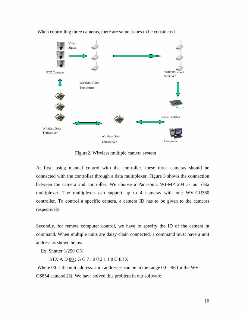
For the base section, there are several choices to implement including tripod-based,
single-pole based and tower based. Figure 13, 14, and 15 show these approaches. For the
tripod-based system, it is very difficult to find good and heavy-duty tripod within a lower
price range. It is very easy to cause camera to shake. For the single-pole system, it is not
stable enough, and it needs a large basement to support a 4 meters high pole. On the
contrary, the tower-based system is very easy to implement, and the cost for material is
not high, and it is heavy-duty, it can supply more stability for the system, with tower, the
system can easily extend to higher height.
2 -3
1 0 -1 1
W ire le s s S tu ff
P o w e r
Figure13 Tripod-based system Figure14 Single-pole system

36
Figure16 shows a camera support bar that is on the top of the camera mounting system.
Some requirements of the support bar are as following:
● Has a movable bar that can hold for camera and change camera position
● Should be made of light weight material
● The arm is long enough that people can move under the camera.
● The material should be strong enough for camera and other necessary
equipment.
We made one with wood, and are working on other better material.
4.2 Installation Manual
There are two version of system. One is wireless version. In this version, we connect the
wireless transmitter and receiver to computer and camera. The other one is the wired
version. In this version, we use cable to connect all the components of the system. The
basic procedure for both connection methods is the same. We will discuss this procedure
step by step.
Figure15 Tower-based system
6 feet
4 feet
Movablepart
Figure16 Camera support bar

37
First, install Matrox Meteor-II frame grabber for computer. Remove the cover of the
computer; insert frame grabber to an empty PCI slot.
Secondly, connect video source. Use BNC cable to connect the video output on the
camera and the video input of the frame grabber. If using wireless version, connect video
transmitter to camera and wireless video receiver to the frame grabber.
Thirdly, camera setting up including setting the camera ID, RS485 setup, remember set
RS485 communication to 2-wire connection. Details please refer to camera manual.
Next, communication setup. This part is really important. On camera RS485 port, there
are 5 pins, which support both 2-wire and 4-wire RS485 communication. In our system,
we use 2-wire connection. So at first, we connect all TB and RB, TA and RA together to
form a three-wire connection including A, B, and ground. Then we connect these three
wires to the RS485 converter, the order should be A to A, B to B, and ground to ground.
Finally, we connect the converter to computer. If it is used in wireless version, a wireless
transceiver will be connected to serial port of computer, another transceiver should be
connected with the RS485 converter through a null-modem module, the reason is both
transceiver and converter are DCE (Data Communication Equipment).
Finally, check the connection again. If everything is ok, just turn on all the power, and
launch the software, you can work with this system.
4.3 System Performance Evaluation We tested our system with both wireless and wired connections. Testing included video
and control data communication.
For wireless communication, we use a setup system as shown in Figure17. In this setup,
the whole system is built on a tripod base. The camera is about 10 feet high. We made the

38
test on 4th floor of Ferris Hall. The results show that the effect communication distance
for video is about 50 feet, and for control data is about 70 feet. There exist some problem
during the test. Image quality is not stable. Objects between transmitter and receiver will
affect the image quality. The reason for this is that firstly the current wireless transmitter
and receiver is not powerful enough. Secondly, the frame grabber is not work well with
wireless communication. It will cause the image to stop or completely lost the image.
Finally, bad connection inside the transmitter and receiver and cable may be a reason for
poor image quality. For control data test, the software can send command to camera, but
cannot receive the feedback from the camera. The first possible reason is that the wireless
transceiver. Sending too many commands may cause the transceiver encode the wrong
command. Since the transceiver can hold 64 byte command, if the command is send too
Figure17. Wireless test system

39
fast, the last command will be cut in the command buffer. The second reason may be the
bugs in the software. Since we compare the feedback with the correct answer. If camera
feedback does not come back through the transceiver, it will cause the software a dead
loop. If this is true, we need to modify the software.
For the wired system, we tested the system with various length cables. We used two ways
to connect the cable, one is to directly connect RS485 converter to the computer, and the
other is connect the RS485 converter to the computer through a 6 foot RS232 cable. We
tested with are 10’, 20’, 30’, 100’, 200’, and 400’ RS485 cable. The result shows that for
cable length less than 200 feet, the whole system works well. There is some delay as
cable become longer. The longer the cable is, the higher the delay is. For 400 feet cable,
the delay is more than 2 seconds; this cause the system cannot get correct feedback from
the camera. One solution is to use a shorter cable for communication; the other solution is
to use a repeater in the middle of the cable. For video, the cable length does not affect the
image quality for cable length less than 400 feet.
5. Experiment Results Various experiments were conducted with our PTZ camera system. The purpose of these
experiments was to apply this system with our tracking algorithm. To simplify the
experiment, we only use wired communication for these experiments. For these
experiments, the PTZ camera was set on the ceiling about 9 feet high, the moving range
of the object was about 13foot by 10foot rectangle in our office.
5.1 Stationary Camera Controlled PTZ Camera System
The first experiment was to use a stationary camera and the PTZ system. The function of
the stationary camera was to capture the object, detect the biggest moving region in the
images, and provide object-moving information such as position and moving direction of
movement for the PTZ camera. The PTZ camera gets information from the stationary
camera. By receiving the moving position command, the PTZ camera changes to the
preset-position, and track the object to get the right view of the object.

40
For this purpose, we determined 12 preset positions in the moving region. We choose 12
points in the region, the distance between two position is set to equal in the x and y
direction, thus the cover range for every position is about 3 feet x 3 feet. Figure 18 shows
all the preset positions. In the algorithm, we use the position of the object head as the
reference. For every preset position, we change the pan and tilt zoom angle of the lens
and the zoom ratio to always keep the object in the middle of the view and the top of the
object at the same height.
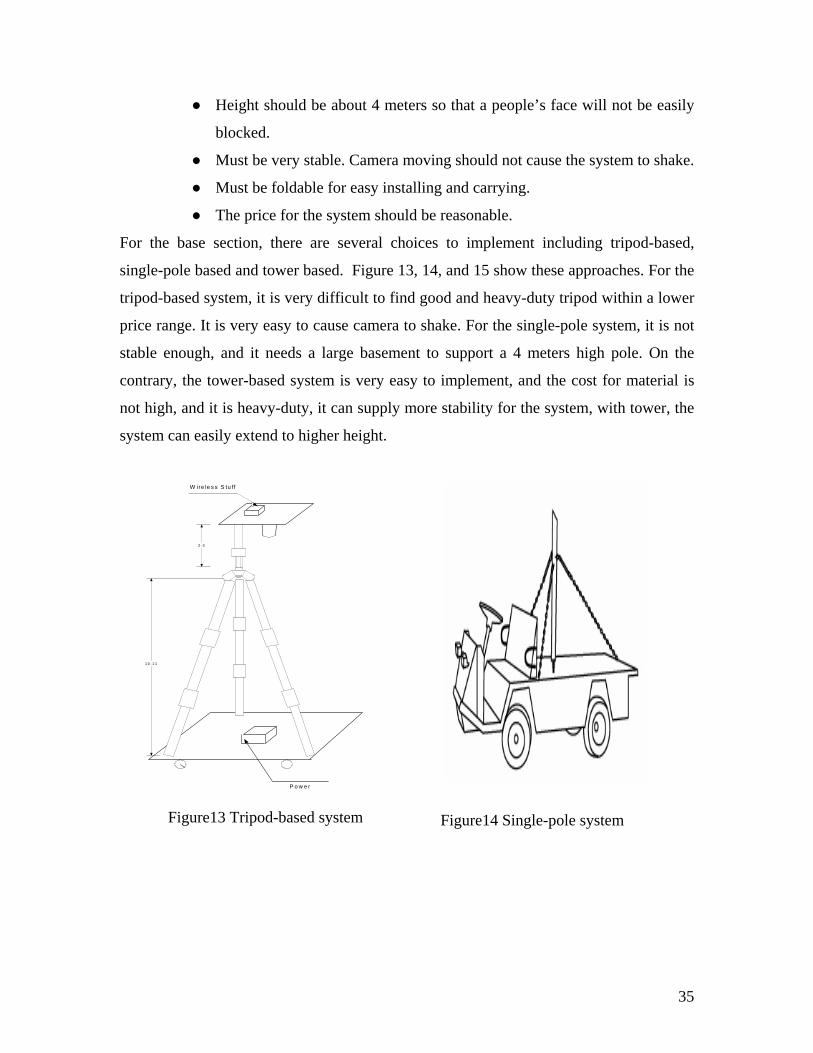
Some frames of the experimental results are shown in Figure 19 (a, b, c, d). In theses
frame, the right images are captured by stationary camera. The rectangle indicates the
moving region. The left images were grabbed by PTZ camera. The results show that
control of the PTZ camera can be achieved by position parameters. For more accurate
control, we need to provide more position information. This experiment will be applied in
a direction detection project, which will be used in airport to detect the object in the
wrong direction of the exit lane. The difference is the PTZ camera will change its view
according to the current position instead of a preset position.
Figure 18. PTZ Camera Preset Position
41
(a)
(d)
(b)
(c)
Figure 19. Sample Frames of Stationary Camera Control Tracking

42
5.2 Color Tracking with PTZ Camera
This experiment was implemented with the PTZ camera. The purpose of this experiment
was to grab images while the camera is rotating. The Multi-rate Gaussian distribution for
each color channel was used to track color region that is initiated by user. Once color
region is defined, we compute the difference between frames. If the difference is smaller
than a threshold, this is considered it the same color region. Based upon the moving
direction of the color region, we send moving command such pan-right, tilt-up, and
combination of pan and tilt to control the moving direction of the PTZ camera. Figure 20
shows some frames of the experimental results. In theses frames, the larger image is the
grabbed image, and the cross in the smaller image marks out the center of the color
region. This algorithm is concentrated on tracking the center of the color region.
Figure 20. Image Sequence of Color Tracking

43
6. Conclusion and Future Plans A hardware implementation of a wireless real-time video tracking system is proposed in
this paper. Its architecture and module definitions are given. The complete system
consists of three PTZ cameras, a wireless video transmitter and receiver, frame grabber,
computer, and wireless transceiver for the control data. The hardware specifications are
discussed. This system can be controlled either by a controller or by a remote computer.
The interface and control of this hardware system is implemented. Control of the camera
is the main task of the controlling system. The software is implemented in Visual C++
and can control the function of the camera such as panning, tilting zooming and focusing;
it can also control ALC, AGC, shutter speed, white balance, Sensitivity, and etc. A
system with single camera was setup and tested. The result shows that the system work
well with wired connection. Cable length will affect the performance of the system. For
wireless communication, some problems exist. These problems are related to the
performance of the wireless transmitter and receiver. We truly believe if we use better
wireless equipment, these problems can be solved. A camera mounting system is
designed for the system. With this mounting system, the whole system can be easily
move around and is stable in various environments.
In the future, a multiple camera system should be setup as soon as possible. Some
necessary test should be completed with the multiple camera system including hardware
and software. The whole system should be tested with video tracking algorithms and be
ready for the final demonstration in the airport.
The GUI for the control software needs to be modified to make it more users friendly and
beautiful. Some functions need to be improved after some test. The sending and read
feedback function should be re-implement for wireless communication. For future use,
we should consider various communication interfaces such as the parallel port, USB port,
and fire-ware port. As an automated goal, the software should work for multiple cameras
and multiple communication interfaces.

44
The digital system is a trend for future video surveillance. For better image quality and
optimum processing speed, this system will upgrade to a digital system. We have
completed a partial survey on digital equipment, as soon as we can solve the existing
problem in current system, we will also work on digital system.
45
References
[1] Koller, D., Klinker, G., Rose, E., Breen, D., Whitaker, R., and Tuceryan, M. “Real-
time Vision-based Camera Tracking for Augmented Reality Applications”, Proceedings
of the ACM Symposium on Virtual Reality Software and Technology (VRST--97), 1997,
Pages 87--94.
[2] Corke, P.I.; Hutchinson, S.A. “Real-time vision, tracking and control”, Robotics and
Automation, 2000. Proceedings. ICRA '00. IEEE International Conference, Volume: 1 ,
2000 Page(s): 622 –629.
[3] Davis, J.W.; Bobick, A.F. “The representation and recognition of human movement
using temporal templates”, Computer Vision and Pattern Recognition, 1997.
Proceedings., 1997 IEEE Computer Society Conference, 1997, Page(s): 928 –934
[4] Haritaoglu I.; Harwood D.; Larry S.D., “W4: Real-time surveillance of people and
their activities”, IEEE Transaction on Pattern Analysis and Machine Intelligence, Vol.
22, No. 8, August, 2000, Page(s): 809 – 830.
[5] Xiaodong Liu; Guangda Su, “A new network-based intelligent surveillance system”,
Signal Processing Proceedings, 2000. WCCC-ICSP 2000. 5th International
Conference, Volume: 2 , 2000, Page(s): 1187 –1192.
[6] Collins R.; Lipton A.; Kanade T.; Fujiyoshi H.; Duggins D.; Tsin Y.; Tolliver D.;
Enomoto N.; and Hasegawa O.; “ A system for video surveillance and monitoring”,
technical report CMU-RI-TR-00-12, Robotics Institute, Carnegie Mellon University,
May, 2000.
[7] Lipton A., Fujiyoshi H., Patil R., “Moving target classification and tracking from
real-time video”, Proceedings, Fourth IEEE Workshop on Applications of Computer
Vision, WACV, 98, October 19—21, 1998, Princeton, New Jersey. Page(s): 8-14

46
[8] Wren, C.R.; Azarbayejani, A.; Darrell, T.; Pentland, A.P. “Pfinder: real-time tracking
of the human body”, Pattern Analysis and Machine Intelligence, IEEE Transactions,
Volume: 19 Issue: 7 , July 1997 Page(s): 780 -785
[9] Rehg, J.M.; Loughlin, M.; Waters, K. “Vision for a smart kiosk”, Computer Vision
and Pattern Recognition, 1997. Proceedings., 1997 IEEE Computer Society Conference,
1997 Page(s): 690 -696
[10] Krumm, J.; Harris, S.; Meyers, B.; Brumitt, B.; Hale, M.; Shafer, S. “Multi-camera
multi-person tracking for EasyLiving”, Visual Surveillance, 2000. Proceedings. Third
IEEE International Workshop, 2000 Page(s): 3 -10
[11] Sherrah, J.; Gong, S. “VIGOUR: A system for tracking and recognition of multiple
people and their activities”, Pattern Recognition, 2000. Proceedings. 15th International
Conference, Volume: 1 , 2000 Page(s): 179 –182.
[12] Yachi, K.; Wada, T.; Matsuyama, T. “Human head tracking using adaptive
appearance models with a fixed-viewpoint pan-tilt-zoom camera”, Automatic Face and
Gesture Recognition, 2000. Proceedings. Fourth IEEE International Conference, 2000
Page(s): 150 -155
[13] Panasonic Company, “protocol information”, Panasonic CCVE Products Document
Number 010, Nov.27.1997
[14] Matrox Imaging Tutorial, “camera Interface Guide”, Page(s) 3-15
[15] WWW.matrox.com
[16] http://www.rs485.com/
[17] Panasonic Company, “Protocol information for WV-CS850”, version 2.0, 2000

47
Appendix
(Camera.cpp, CameraCommand.cpp, CommandQueue.cpp, CcontrolDlg.cpp and serial.cpp)
// Camera.cpp: implementation of the CCamera class. #include "stdafx.h" #include "ControlCommand.h" #include "Camera.h" #ifdef _DEBUG #undef THIS_FILE static char THIS_FILE[]=__FILE__; #define new DEBUG_NEW #endif /////////////////////////////////////////////////////////////////////////////////// // // Various camera function commands and their answer. // /////////////////////////////////////////////////////////////////////////////////// CCameraCommand CCamera::s_Zoom("[GCN:20214B0:2022**8:2022**1]","[GC7:202E4B0][GC7:2029**8][GC7:2029**1]"); CCameraCommand CCamera::s_Focus("[GCN:20214B1:2022**8:2022**1]","[GC7:202E4B1][GC7:2029**8][GC7:2029**1]"); CCameraCommand CCamera::s_Pan("[GCN:20214C0:2022**8:2022**1]","[GC7:202E4C0][GC7:2029**8][GC7:2029**1]"); CCameraCommand CCamera::s_Tilt("[GCN:20214C1:2022**8:2022**1]","[GC7:202E4C1][GC7:2029**8][GC7:2029**1]"); CCameraCommand CCamera::s_PosCall("[GCF:2021400:2022**0]","[GC7:202E400][GC7:2029**0]"); CCameraCommand CCamera::s_GetZoom("[GCF:2021490:20204A0]","[GC7:20249**][GC7:2024A**]"); CCameraCommand CCamera::s_GetFocus("[GCF:20204B0:20204C0]","[GC7:2024B**][GC7:2024C**]"); CCameraCommand CCamera::s_GetPan("[GCF:20203A0:20203B0]","[GC7:2023A**][GC7:2023B**]"); CCameraCommand CCamera::s_GetTilt("[GCF:20203C0:20203D0]","[GC7:2023C**][GC7:2023D**]"); CCameraCommand CCamera::s_Reset("[GCF:2021400:2022000]","[GC7:002E400][GC7:2029000]");

48
CCameraCommand CCamera::s_HomePosition("[GCF:2021400:20223F0]","[GC7:002E400][GC7:20293F0]"); CCameraCommand CCamera::s_SetPosition("[GCV:2021540:2022**0:2021542:2021543]","[GC7:202E540][GC7:2029**0][GC7:202E542][GC7:202E543]"); CCameraCommand CCamera::s_GetPosition("[GCF:2021400:2022**0]","[GC7:202E400][GC7:2029**0]"); CCameraCommand CCamera::s_IRISManual("[GC7:0021034]","[GC7:002E034]"); CCameraCommand CCamera::s_ALCOn("[GC7:0021032]","[GC7:002E032]"); CCameraCommand CCamera::s_IRISOpen("[GC7:0021002]","[GC7:002E002]"); CCameraCommand CCamera::s_IRISClose("[GC7:0021003]","[GC7:002E003]"); CCameraCommand CCamera::s_IRISStop("[GC7:0021004]","[GC7:002E004]"); CCameraCommand CCamera::s_IRISReset("[GC7:0021005]","[GC7:002E005]"); CCameraCommand CCamera::s_AGCOn("[GC7:0021200]","[GC7:002E200]"); CCameraCommand CCamera::s_AGCOff("[GC7:0021201]","[GC7:002E201]"); CCameraCommand CCamera::s_AGCLow("[GC7:0021208]","[GC7:002E208]"); CCameraCommand CCamera::s_AGCMid("[GC7:0021209]","[GC7:002E209]"); CCameraCommand CCamera::s_AGCHigh("[GC7:002120A]","[GC7:002E20A]"); CCameraCommand CCamera::s_AFOn("[GC7:0021A06]","[GC7:002EA06]"); CCameraCommand CCamera::s_AFSmall("[GC7:0021A18]","[GC7:002EA18]"); CCameraCommand CCamera::s_AFMiddle("[GC7:0021A19]","[GC7:002EA19]"); CCameraCommand CCamera::s_AFLarge("[GC7:0021A1A]","[GC7:002EA1A]"); CCameraCommand CCamera::s_IRISStatus("[GC7:0020102]","[GC7:002102*]"); CCameraCommand CCamera::s_AGCStatus("[GC7:0020121]","[GC7:002121*]"); CCameraCommand CCamera::s_AFStatus("[GC7:00201A2]","[GC7:0021A2*]"); CCameraCommand CCamera::s_SensAutoOn("[GC7:0021120]","[GC7:002E120]"); CCameraCommand CCamera::s_SensAutoOff("[GC7:0021121]","[GC7:002E121]"); CCameraCommand CCamera::s_SensAutoInc("[GC7:0021122]","[GC7:002E122]"); CCameraCommand CCamera::s_SensAutoDec("[GC7:0021123]","[GC7:002E123]"); CCameraCommand CCamera::s_SensAutoStatus("[GC7:0020112]","[GC7:00211**]"); CCameraCommand CCamera::s_SensManualOn("[GC7:0020150]","[GC7:002E150]"); CCameraCommand CCamera::s_SensManualOff("[GC7:0020151]","[GC7:002E151]"); CCameraCommand CCamera::s_SensManualInc("[GC7:0020152]","[GC7:002E152]"); CCameraCommand CCamera::s_SensManualDec("[GC7:0020153]","[GC7:002E153]"); CCameraCommand CCamera::s_SensManualStatus("[GC7:0020116]","[GC7:00211**]"); CCameraCommand CCamera::s_ATWOn("[GC7:0021310]","[GC7:002E310]"); CCameraCommand CCamera::s_AWCOn("[GC7:0021300]","[GC7:002E300]"); CCameraCommand CCamera::s_AWCReset("[GC7:0021305]","[GC7:002E305]"); CCameraCommand CCamera::s_AWCSetup("[GCF:0021300:0021306]","[GC7:002E300][GC7:002E306]"); CCameraCommand CCamera::s_WBStatus("[GC7:0020130]","[GC7:002130*]"); CCameraCommand CCamera::s_ShutterOn("[GC7:0021100]","[GC7:002E100]"); CCameraCommand CCamera::s_ShutterOff("[GC7:0021101]","[GC7:002E101]"); CCameraCommand CCamera::s_ShutterInc("[GC7:0021102]","[GC7:002E102]");

49
CCameraCommand CCamera::s_ShutterDec("[GC7:0021103]","[GC7:002E103]"); CCameraCommand CCamera::s_Shutter100("[GC7:0021109]","[GC7:002E109]"); CCameraCommand CCamera::s_Shutter250("[GC7:002110C]","[GC7:002E10C]"); CCameraCommand CCamera::s_Shutter500("[GC7:002110D]","[GC7:002E10D]"); CCameraCommand CCamera::s_Shutter1000("[GC7:002110E]","[GC7:002E10E]"); CCameraCommand CCamera::s_Shutter2000("[GC7:002110F]","[GC7:002E10F]"); CCameraCommand CCamera::s_Shutter4000("[GC7:0021119]","[GC7:002E119]"); CCameraCommand CCamera::s_Shutter10000("[GC7:002111A]","[GC7:002E11A]"); CCameraCommand CCamera::s_ShutterStatus("[GC7:0020110]","[GC7:00211**]"); CCameraCommand CCamera::s_PanRightS("[GC7:202135C]","[GC7:202E35C]"); CCameraCommand CCamera::s_PanRightF("[GC7:202132C]","[GC7:202E32C]"); CCameraCommand CCamera::s_PanLeftS("[GC7:2021358]","[GC7:202E358]"); CCameraCommand CCamera::s_PanLeftF("[GC7:2021328]","[GC7:202E328]"); CCameraCommand CCamera::s_TiltUpS("[GC7:202135A]","[GC7:202E35A]"); CCameraCommand CCamera::s_TiltUpF("[GC7:202132A]","[GC7:202E32A]"); CCameraCommand CCamera::s_TiltDownS("[GC7:202135E]","[GC7:202E35E]"); CCameraCommand CCamera::s_TiltDownF("[GC7:202132E]","[GC7:202E32E]"); CCameraCommand CCamera::s_PanRSTiltUS("[GC7:202135B]","[GC7:202E35B]"); CCameraCommand CCamera::s_PanRSTiltUF("[GC7:202134B]","[GC7:202E34B]"); CCameraCommand CCamera::s_PanRFTiltUS("[GC7:202133B]","[GC7:202E33B]"); CCameraCommand CCamera::s_PanRFTiltUF("[GC7:202132B]","[GC7:202E32B]"); CCameraCommand CCamera::s_PanLSTiltUS("[GC7:2021359]","[GC7:202E359]"); CCameraCommand CCamera::s_PanLSTiltUF("[GC7:2021349]","[GC7:202E349]"); CCameraCommand CCamera::s_PanLFTiltUS("[GC7:2021339]","[GC7:202E339]"); CCameraCommand CCamera::s_PanLFTiltUF("[GC7:2021329]","[GC7:202E329]"); CCameraCommand CCamera::s_PanRSTiltDS("[GC7:202135D]","[GC7:202E35D]"); CCameraCommand CCamera::s_PanRSTiltDF("[GC7:202134D]","[GC7:202E34D]"); CCameraCommand CCamera::s_PanRFTiltDS("[GC7:202133D]","[GC7:202E33D]"); CCameraCommand CCamera::s_PanRFTiltDF("[GC7:202132D]","[GC7:202E32D]"); CCameraCommand CCamera::s_PanLSTiltDS("[GC7:202135F]","[GC7:202E35F]"); CCameraCommand CCamera::s_PanLSTiltDF("[GC7:202134F]","[GC7:202E34F]"); CCameraCommand CCamera::s_PanLFTiltDS("[GC7:202133F]","[GC7:202E33F]"); CCameraCommand CCamera::s_PanLFTiltDF("[GC7:202132F]","[GC7:202E32F]"); CCameraCommand CCamera::s_CameraStopSS("[GC7:2021354]","[GC7:202E354]"); CCameraCommand CCamera::s_CameraStopSF("[GC7:2021344]","[GC7:202E344]"); CCameraCommand CCamera::s_CameraStopFS("[GC7:2021334]","[GC7:202E334]"); CCameraCommand CCamera::s_CameraStopFF("[GC7:2021324]","[GC7:202E324]"); ////////////////////////////////////////////////////////////////////// // Construction/Destruction ////////////////////////////////////////////////////////////////////// CCamera::CCamera() :m_ID("") // initialize m_ID { } CCamera::~CCamera() {

50
} CCamera::CCamera(CCommandQueue *pCommandQueue, CString sCarmeraID) :m_ID(sCarmeraID) { m_pCommandQueue = pCommandQueue; } // Zoom function int CCamera::Zoom(float fZoom) { char buff[5]; sprintf(buff, "%04d", (int)(fZoom)%10000); CControlCommand tempCommand(m_ID); // get camera ID tempCommand.AddCameraCommand(s_Zoom, buff); // Get send command and parameters m_pCommandQueue->AddCommand(tempCommand); // Send command to command array return 0; } //Camera move function including pan and tilt with coordinate position void CCamera::MoveToAngle(float fX, float fY) { char buff[5]; CControlCommand tempCommand(m_ID); sprintf(buff, "%04d", (int)(fX*10)%10000); tempCommand.AddCameraCommand(s_Pan, buff); sprintf(buff, "%04d", (int)(fY*10)%10000); tempCommand.AddCameraCommand(s_Tilt, buff); m_pCommandQueue->AddCommand(tempCommand); } //Goto preset position void CCamera::GotoPosition(int iPos) { char buff[5]; sprintf(buff, "%02d", iPos%100); CControlCommand tempCommand(m_ID); tempCommand.AddCameraCommand(s_PosCall, buff); m_pCommandQueue->AddCommand(tempCommand); } //FOcusing function with position void CCamera::Focuse(float fDis) { char buff[5]; sprintf(buff, "%04d", (int)(fDis*10)%10000); CControlCommand tempCommand(m_ID); tempCommand.AddCameraCommand(s_Focus, buff);

51
m_pCommandQueue->AddCommand(tempCommand); } //Manual IRIS function void CCamera::IRISManual() { CControlCommand tempCommand(m_ID); tempCommand.AddCameraCommand(s_IRISManual, ""); m_pCommandQueue->AddCommand(tempCommand); } // Automatic light control function void CCamera::ALCOn() { CControlCommand tempCommand(m_ID); tempCommand.AddCameraCommand(s_ALCOn, ""); m_pCommandQueue->AddCommand(tempCommand); } //Get pan angle function void CCamera::GetPan() { CControlCommand tempCommand(m_ID); tempCommand.AddCameraCommand(s_GetPan, ""); m_pCommandQueue->AddCommand(tempCommand); } //Get tilt angle function void CCamera::GetTilt() { CControlCommand tempCommand(m_ID); tempCommand.AddCameraCommand(s_GetTilt, ""); m_pCommandQueue->AddCommand(tempCommand); } //Goto preset home position1 void CCamera::Reset() { CControlCommand tempCommand(m_ID); tempCommand.AddCameraCommand(s_Reset, ""); m_pCommandQueue->AddCommand(tempCommand); } //Goto camera homeposition (0,0) void CCamera::HomePosition() { CControlCommand tempCommand(m_ID); tempCommand.AddCameraCommand(s_HomePosition, ""); m_pCommandQueue->AddCommand(tempCommand); } //Manual IRIS open function, timeout 2.2 second unless get "stop" command void CCamera::IRISOpen()

52
{ CControlCommand tempCommand(m_ID); tempCommand.AddCameraCommand(s_IRISOpen, ""); m_pCommandQueue->AddCommand(tempCommand); } //Manual IRIS close function, timeout 2.2 second unless get "stop" command void CCamera::IRISClose() { CControlCommand tempCommand(m_ID); tempCommand.AddCameraCommand(s_IRISClose, ""); m_pCommandQueue->AddCommand(tempCommand); } //Manual IRIS stop function void CCamera::IRISStop() { CControlCommand tempCommand(m_ID); tempCommand.AddCameraCommand(s_IRISStop, ""); m_pCommandQueue->AddCommand(tempCommand); } //Iris reset to original setting void CCamera::IRISReset() { CControlCommand tempCommand(m_ID); tempCommand.AddCameraCommand(s_IRISReset, ""); m_pCommandQueue->AddCommand(tempCommand); } //Automatic gain control on function void CCamera::AGCOn() { CControlCommand tempCommand(m_ID); tempCommand.AddCameraCommand(s_AGCOn, ""); m_pCommandQueue->AddCommand(tempCommand); } //Automatic gain control off function void CCamera::AGCOff() { CControlCommand tempCommand(m_ID); tempCommand.AddCameraCommand(s_AGCOff, ""); m_pCommandQueue->AddCommand(tempCommand); } //Manual set AGC to low level void CCamera::AGCLow() { CControlCommand tempCommand(m_ID); tempCommand.AddCameraCommand(s_AGCLow, ""); m_pCommandQueue->AddCommand(tempCommand);

53
} //Manual set AGC to mid level void CCamera::AGCMid() { CControlCommand tempCommand(m_ID); tempCommand.AddCameraCommand(s_AGCMid, ""); m_pCommandQueue->AddCommand(tempCommand); } //Manual set AGC to high level void CCamera::AGCHigh() { CControlCommand tempCommand(m_ID); tempCommand.AddCameraCommand(s_AGCHigh, ""); m_pCommandQueue->AddCommand(tempCommand); } //Automatic focus on void CCamera::AFOn() { CControlCommand tempCommand(m_ID); tempCommand.AddCameraCommand(s_AFOn, ""); m_pCommandQueue->AddCommand(tempCommand); } //Automatic small region focus void CCamera::AFSmall() { CControlCommand tempCommand(m_ID); tempCommand.AddCameraCommand(s_AFSmall, ""); m_pCommandQueue->AddCommand(tempCommand); } //Automatic middle region focus void CCamera::AFMiddle() { CControlCommand tempCommand(m_ID); tempCommand.AddCameraCommand(s_AFMiddle, ""); m_pCommandQueue->AddCommand(tempCommand); } //Automatic large region focus void CCamera::AFLarge() { CControlCommand tempCommand(m_ID); tempCommand.AddCameraCommand(s_AFLarge, ""); m_pCommandQueue->AddCommand(tempCommand); } //Set preset position function void CCamera::SetPosition(CString Pos) {

54
char buff[5]; sprintf(buff, "%s", Pos); CControlCommand tempCommand(m_ID); tempCommand.AddCameraCommand(s_SetPosition, buff); m_pCommandQueue->AddCommand(tempCommand); } //Goto preset position void CCamera::GetPosition(CString GPos) { char buff[5]; sprintf(buff, "%s", GPos); CControlCommand tempCommand(m_ID); tempCommand.AddCameraCommand(s_GetPosition, buff); m_pCommandQueue->AddCommand(tempCommand); } //Check IRIS status function void CCamera::IRISSTATUS() { CControlCommand tempCommand(m_ID); tempCommand.AddCameraCommand(s_IRISStatus, ""); m_pCommandQueue->AddCommand(tempCommand); } //Check AGC status function void CCamera::AGCStatus() { CControlCommand tempCommand(m_ID); tempCommand.AddCameraCommand(s_AGCStatus, ""); m_pCommandQueue->AddCommand(tempCommand); } //Check automatic focus status void CCamera::AFStatus() { CControlCommand tempCommand(m_ID); tempCommand.AddCameraCommand(s_AFStatus, ""); m_pCommandQueue->AddCommand(tempCommand); } //Auto sensitivity on void CCamera::SensAutoOn() { CControlCommand tempCommand(m_ID); tempCommand.AddCameraCommand(s_SensAutoOn, ""); m_pCommandQueue->AddCommand(tempCommand); } //Auto sensitivity off void CCamera::SensAutoOff() {

55
CControlCommand tempCommand(m_ID); tempCommand.AddCameraCommand(s_SensAutoOff, ""); m_pCommandQueue->AddCommand(tempCommand); } //Auto sensitivity increase void CCamera::SensAutoInc() { CControlCommand tempCommand(m_ID); tempCommand.AddCameraCommand(s_SensAutoInc, ""); m_pCommandQueue->AddCommand(tempCommand); } ////Auto sensitivity decrease void CCamera::SensAutoDec() { CControlCommand tempCommand(m_ID); tempCommand.AddCameraCommand(s_SensAutoDec, ""); m_pCommandQueue->AddCommand(tempCommand); } //check auto sensitivity status void CCamera::SensAutoStatus() { CControlCommand tempCommand(m_ID); tempCommand.AddCameraCommand(s_SensAutoStatus, ""); m_pCommandQueue->AddCommand(tempCommand); } //Manual sensitivity on void CCamera::SensManualOn() { CControlCommand tempCommand(m_ID); tempCommand.AddCameraCommand(s_SensManualOn, ""); m_pCommandQueue->AddCommand(tempCommand); } //Manual sensitivity off void CCamera::SensManualOff() { CControlCommand tempCommand(m_ID); tempCommand.AddCameraCommand(s_SensManualOff, ""); m_pCommandQueue->AddCommand(tempCommand); } //Manual sensitivity increase void CCamera::SensManualInc() { CControlCommand tempCommand(m_ID); tempCommand.AddCameraCommand(s_SensManualInc, ""); m_pCommandQueue->AddCommand(tempCommand); }

56
//Manual sensitivity decrease void CCamera::SensManualDec() { CControlCommand tempCommand(m_ID); tempCommand.AddCameraCommand(s_SensManualDec, ""); m_pCommandQueue->AddCommand(tempCommand); } //Manual sensitivity status void CCamera::SensManualStatus() { CControlCommand tempCommand(m_ID); tempCommand.AddCameraCommand(s_SensManualStatus, ""); m_pCommandQueue->AddCommand(tempCommand); } //WHite balance ATW on void CCamera::ATWOn() { CControlCommand tempCommand(m_ID); tempCommand.AddCameraCommand(s_ATWOn, ""); m_pCommandQueue->AddCommand(tempCommand); } //White balance AWC on void CCamera::AWCOn() { CControlCommand tempCommand(m_ID); tempCommand.AddCameraCommand(s_AWCOn, ""); m_pCommandQueue->AddCommand(tempCommand); } //AWC reset void CCamera::AWCReset() { CControlCommand tempCommand(m_ID); tempCommand.AddCameraCommand(s_AWCReset, ""); m_pCommandQueue->AddCommand(tempCommand); } //AWC setup void CCamera::AWCSetup() { CControlCommand tempCommand(m_ID); tempCommand.AddCameraCommand(s_AWCSetup, ""); m_pCommandQueue->AddCommand(tempCommand); } //white balance status void CCamera::WBStatus() { CControlCommand tempCommand(m_ID);

57
tempCommand.AddCameraCommand(s_WBStatus, ""); m_pCommandQueue->AddCommand(tempCommand); } //Shutter speed manual on void CCamera::ShutterOn() { CControlCommand tempCommand(m_ID); tempCommand.AddCameraCommand(s_ShutterOn, ""); m_pCommandQueue->AddCommand(tempCommand); } //shutter speed off (shutter speed = 1/60) void CCamera::ShutterOff() { CControlCommand tempCommand(m_ID); tempCommand.AddCameraCommand(s_ShutterOff, ""); m_pCommandQueue->AddCommand(tempCommand); } //manual increase shutter speed void CCamera::ShutterInc() { CControlCommand tempCommand(m_ID); tempCommand.AddCameraCommand(s_ShutterInc, ""); m_pCommandQueue->AddCommand(tempCommand); } //Manual decrease shutter speed void CCamera::ShutterDec() { CControlCommand tempCommand(m_ID); tempCommand.AddCameraCommand(s_ShutterDec, ""); m_pCommandQueue->AddCommand(tempCommand); } //Shutter speed = 1/100 void CCamera::Shutter100() { CControlCommand tempCommand(m_ID); tempCommand.AddCameraCommand(s_Shutter100, ""); m_pCommandQueue->AddCommand(tempCommand); } //Shutter speed = 1/250 void CCamera::Shutter250() { CControlCommand tempCommand(m_ID); tempCommand.AddCameraCommand(s_Shutter250, ""); m_pCommandQueue->AddCommand(tempCommand); } //Shutter speed = 1/500

58
void CCamera::Shutter500() { CControlCommand tempCommand(m_ID); tempCommand.AddCameraCommand(s_Shutter500, ""); m_pCommandQueue->AddCommand(tempCommand); } //Shutter speed = 1/1000 void CCamera::Shutter1000() { CControlCommand tempCommand(m_ID); tempCommand.AddCameraCommand(s_Shutter1000, ""); m_pCommandQueue->AddCommand(tempCommand); } //Shutter speed = 1/2000 void CCamera::Shutter2000() { CControlCommand tempCommand(m_ID); tempCommand.AddCameraCommand(s_Shutter2000, ""); m_pCommandQueue->AddCommand(tempCommand); } //Shutter speed = 1/4000 void CCamera::Shutter4000() { CControlCommand tempCommand(m_ID); tempCommand.AddCameraCommand(s_Shutter4000, ""); m_pCommandQueue->AddCommand(tempCommand); } //Shutter speed = 1/10000 void CCamera::Shutter10000() { CControlCommand tempCommand(m_ID); tempCommand.AddCameraCommand(s_Shutter10000, ""); m_pCommandQueue->AddCommand(tempCommand); } //check shutter status void CCamera::ShutterStatus() { CControlCommand tempCommand(m_ID); tempCommand.AddCameraCommand(s_ShutterStatus, ""); m_pCommandQueue->AddCommand(tempCommand); } //Pan right slow void CCamera::PanRightS() { CControlCommand tempCommand(m_ID); tempCommand.AddCameraCommand(s_PanRightS, "");

59
m_pCommandQueue->AddCommand(tempCommand); } //Pan right fast void CCamera::PanRightF() { CControlCommand tempCommand(m_ID); tempCommand.AddCameraCommand(s_PanRightF, ""); m_pCommandQueue->AddCommand(tempCommand); } //Pan left slow void CCamera::PanLeftS() { CControlCommand tempCommand(m_ID); tempCommand.AddCameraCommand(s_PanLeftS, ""); m_pCommandQueue->AddCommand(tempCommand); } //Pan left fast void CCamera::PanLeftF() { CControlCommand tempCommand(m_ID); tempCommand.AddCameraCommand(s_PanLeftF, ""); m_pCommandQueue->AddCommand(tempCommand); } //Tilt up slow void CCamera::TiltUpS() { CControlCommand tempCommand(m_ID); tempCommand.AddCameraCommand(s_TiltUpS, ""); m_pCommandQueue->AddCommand(tempCommand); } //Tilt down fast void CCamera::TiltDownF() { CControlCommand tempCommand(m_ID); tempCommand.AddCameraCommand(s_TiltDownF, ""); m_pCommandQueue->AddCommand(tempCommand); } //Tilt up fast void CCamera::TiltUpF() { CControlCommand tempCommand(m_ID); tempCommand.AddCameraCommand(s_TiltUpF, ""); m_pCommandQueue->AddCommand(tempCommand); } //Tilt down slow void CCamera::TiltDownS()

60
{ CControlCommand tempCommand(m_ID); tempCommand.AddCameraCommand(s_TiltDownS, ""); m_pCommandQueue->AddCommand(tempCommand); } //Pan right slow and tilt up slow void CCamera::PanRSTiltUS() { CControlCommand tempCommand(m_ID); tempCommand.AddCameraCommand(s_PanRSTiltUS, ""); m_pCommandQueue->AddCommand(tempCommand); } //Pan right slow and tilt up fast void CCamera::PanRSTiltUF() { CControlCommand tempCommand(m_ID); tempCommand.AddCameraCommand(s_PanRSTiltUF, ""); m_pCommandQueue->AddCommand(tempCommand); } //Pan right fast and tilt up slow void CCamera::PanRFTiltUS() { CControlCommand tempCommand(m_ID); tempCommand.AddCameraCommand(s_PanRFTiltUS, ""); m_pCommandQueue->AddCommand(tempCommand); } //pan right fast and tilt up fast void CCamera::PanRFTiltUF() { CControlCommand tempCommand(m_ID); tempCommand.AddCameraCommand(s_PanRFTiltUF, ""); m_pCommandQueue->AddCommand(tempCommand); } //Pan left slow and tilt up slow void CCamera::PanLSTiltUS() { CControlCommand tempCommand(m_ID); tempCommand.AddCameraCommand(s_PanLSTiltUS, ""); m_pCommandQueue->AddCommand(tempCommand); } //Pan left slow and tilt up fast void CCamera::PanLSTiltUF() { CControlCommand tempCommand(m_ID); tempCommand.AddCameraCommand(s_PanLSTiltUF, ""); m_pCommandQueue->AddCommand(tempCommand);

61
} //Pan left fast and tilt up slow void CCamera::PanLFTiltUS() { CControlCommand tempCommand(m_ID); tempCommand.AddCameraCommand(s_PanLFTiltUS, ""); m_pCommandQueue->AddCommand(tempCommand); } //Pan left fast and tilt up fast void CCamera::PanLFTiltUF() { CControlCommand tempCommand(m_ID); tempCommand.AddCameraCommand(s_PanLFTiltUF, ""); m_pCommandQueue->AddCommand(tempCommand); } //Camera stop moving void CCamera::CameraStopFF() { CControlCommand tempCommand(m_ID); tempCommand.AddCameraCommand(s_CameraStopFF, ""); m_pCommandQueue->AddCommand(tempCommand); } //pan right slow and tilt down slow void CCamera::panRSTiltDS() { CControlCommand tempCommand(m_ID); tempCommand.AddCameraCommand(s_PanRSTiltDS, ""); m_pCommandQueue->AddCommand(tempCommand); } //Pan right slow and tilt down fast void CCamera::PanRSTiltDF() { CControlCommand tempCommand(m_ID); tempCommand.AddCameraCommand(s_PanRSTiltDF, ""); m_pCommandQueue->AddCommand(tempCommand); } //Pan right fast anf tilt down slow void CCamera::PanRFTiltDS() { CControlCommand tempCommand(m_ID); tempCommand.AddCameraCommand(s_PanRFTiltDS, ""); m_pCommandQueue->AddCommand(tempCommand); } //Pan right fast and tilt down fast void CCamera::PanRFTiltDF() {

62
CControlCommand tempCommand(m_ID); tempCommand.AddCameraCommand(s_PanRFTiltDF, ""); m_pCommandQueue->AddCommand(tempCommand); } //Pan left slow anf tilt down slow void CCamera::PanLSTiltDS() { CControlCommand tempCommand(m_ID); tempCommand.AddCameraCommand(s_PanLSTiltDS, ""); m_pCommandQueue->AddCommand(tempCommand); } //Pan leftslow and tilt down fast void CCamera::PanLSTiltDF() { CControlCommand tempCommand(m_ID); tempCommand.AddCameraCommand(s_PanLSTiltDF, ""); m_pCommandQueue->AddCommand(tempCommand); } //Pan left fast anf tilt down slow void CCamera::PanLFTiltDS() { CControlCommand tempCommand(m_ID); tempCommand.AddCameraCommand(s_PanLFTiltDS, ""); m_pCommandQueue->AddCommand(tempCommand); } //Pan left fast and tilt down fast void CCamera::PanLFTiltDF() { CControlCommand tempCommand(m_ID); tempCommand.AddCameraCommand(s_PanLFTiltDF, ""); m_pCommandQueue->AddCommand(tempCommand); } //Pan with coordinate position void CCamera::Pan(float x) { char buff[5]; sprintf(buff, "%04d", (int)(x*10)%10000); CControlCommand tempCommand(m_ID); tempCommand.AddCameraCommand(s_Pan, buff); m_pCommandQueue->AddCommand(tempCommand); } //Tilt with coordinate position void CCamera::Tilt(float y) { char buff[5]; sprintf(buff, "%04d", (int)(y*10)%10000);

63
CControlCommand tempCommand(m_ID); tempCommand.AddCameraCommand(s_Tilt, buff); m_pCommandQueue->AddCommand(tempCommand); } // CameraCommand.cpp: implementation of the CCameraCommand class. ////////////////////////////////////////////////////////////////////// #include "stdafx.h" //#include "CControl.h" #include "CameraCommand.h" #ifdef _DEBUG #undef THIS_FILE static char THIS_FILE[]=__FILE__; #define new DEBUG_NEW #endif const char CCameraCommand::s_STX = 0x2; const char CCameraCommand::s_ETX = 0x3; const char CCameraCommand::s_ACK = 0x6; const char CCameraCommand::s_IDSep = ';'; // Construction/Destruction CCameraCommand::CCameraCommand() { } CCameraCommand::~CCameraCommand() { } ////////////////////////////////////////////////////////////////////// //replace some parameters with command format parameters CCameraCommand::CCameraCommand(std::string strOut, std::string strIn) :m_OutString(strOut), m_InString(strIn) { int i; for(i=0; (i = m_OutString.find("[", i)) != std::string::npos; i++) //find "[", replace with "STX" { m_OutString[i] = CCameraCommand::s_STX; } for(i=0; (i = m_OutString.find("]", i)) != std::string::npos; i++) //find "]", replace with "ETX" { m_OutString[i] = CCameraCommand::s_ETX; } for(i=0; (i = m_InString.find("[", i)) != std::string::npos; i++) //find "[", replace with "STX"

64
{ m_InString[i] = CCameraCommand::s_STX; } for(i=0; (i = m_InString.find("]", i)) != std::string::npos; i++) //find "]", replace with "ETX" { m_InString[i] = CCameraCommand::s_ETX; } int iPos; for(i = 0, iPos = 0; (iPos = m_OutString.find("*", iPos)) != std::string::npos; i++, iPos++) m_OutParamPos.insert(m_OutParamPos.end(),iPos); for(i = 0, iPos = 0; (iPos = m_InString.find("*", iPos)) != std::string::npos; i++, iPos++) m_InParamPos.insert(m_InParamPos.end(),iPos); } //Is this command a valid command bool CCameraCommand::ValidCommand(std::string sParam) { if((m_InParamPos.size() <= sParam.length()) && (m_OutParamPos.size() <= sParam.length())) return true; else return true; } //insert parameters and camera ID into command std::string CCameraCommand::GetSendCommand(std::string sParam, std::string sCameraID) { if(ValidCommand(sParam)) { std::string tempString(m_OutString); for(int i = 0; i < m_OutParamPos.size(); i++) { tempString[m_OutParamPos[i]] = sParam[i]; } if(sCameraID.length() > 0) { sCameraID.insert(sCameraID.end(), s_IDSep); for(int i=0; (i = tempString.find(s_STX, i)) != std::string::npos; i++) tempString.insert(i+1, sCameraID); } return tempString; } else return ""; } //Convert command from standard string to CString CString CCameraCommand::GetSendCommand(CString sParam, CString sCameraID) {
65
return GetSendCommand(std::string((LPCTSTR)sParam), (LPCTSTR)sCameraID).c_str(); } //insert parameters and camera ID into correct answer string std::string CCameraCommand::GetReceiveCommand(std::string sParam, std::string sCameraID) { if(ValidCommand(sParam) && sParam.length()>0) { std::string tempString(m_InString); for(int i = 0; i < m_InParamPos.size(); i++) { tempString[m_InParamPos[i]] = sParam[i]; } if(sCameraID.length() > 0) { sCameraID.insert(sCameraID.end(), s_IDSep); for(int i=0; (i = tempString.find(s_STX, i)) != std::string::npos; i++) tempString.insert(i+1, sCameraID); } return tempString; } else { std::string tempString(m_InString); if(sCameraID.length() > 0) { sCameraID.insert(sCameraID.end(), s_IDSep); for(int i=0; (i = tempString.find(s_STX, i)) != std::string::npos; i++) tempString.insert(i+1, sCameraID); } return tempString; } } //get correct answer with no parameters std::string CCameraCommand::GetNoParamReceiveCommand(std::string sCameraID) { std::string tempString(m_InString); if(sCameraID.length() > 0) { sCameraID.insert(sCameraID.end(), s_IDSep); for(int i=0; (i = tempString.find(s_STX, i)) != std::string::npos; i++) tempString.insert(i+1, sCameraID); }

66
return tempString; } //Convert correct answer from standard string to CString CString CCameraCommand::GetReceiveCommand(CString sParam, CString sCameraID) { return GetReceiveCommand(std::string((LPCTSTR)sParam), (LPCTSTR)sCameraID).c_str(); } //Compare received answer with correct answer bool CCameraCommand::CompareToReceived(std::string sCameraID, std::string strReceived, std::string& sParamOut) { sParamOut.erase(sParamOut.begin(),sParamOut.end());//get rid of the parameters std::string tempString = GetNoParamReceiveCommand(sCameraID); if(tempString.size() == strReceived.size()) { for(int i=0; (i = tempString.find("*", i)) != std::string::npos; i++) { sParamOut += strReceived[i]; strReceived[i] = '*'; //replace parameter in received answer with "*" } if(tempString.compare(strReceived) == 0) return true; } return false; } //Convert from standard string to CString bool CCameraCommand::CompareToReceived(CString sCameraID, CString strReceived, CString& sParamOut) { std::string tempString; bool bReturn = CompareToReceived(std::string((LPCTSTR)sCameraID), (LPCTSTR)strReceived, tempString); sParamOut = tempString.c_str(); return bReturn; } // CommandQueue.cpp : implementation file // This is the thread which send commands to camera and read answers from camera #include "stdafx.h" //#include "myThread.h" #include "CommandQueue.h" #include "Serial.h"

67
#ifdef _DEBUG #define new DEBUG_NEW #undef THIS_FILE static char THIS_FILE[] = __FILE__; #endif #include "resource.h" ///////////////////////////////////////////////////////////////////////////// // CCommandQueue // Construction/Destruction ///////////////////////////////////////////////////////////////////////////// IMPLEMENT_DYNCREATE(CCommandQueue, CWinThread) CCommandQueue::CCommandQueue() :m_KillThread(false) { m_bAutoDelete = false; m_Serial.Open(1,9600); } CCommandQueue::CCommandQueue(HWND hParent) :m_KillThread(false), m_hParent(hParent) { m_bAutoDelete = false; m_Serial.Open(1,9600); } CCommandQueue::~CCommandQueue() { } BOOL CCommandQueue::InitInstance() { // TODO: perform and per-thread initialization here return TRUE; } int CCommandQueue::ExitInstance() { // TODO: perform any per-thread cleanup here return CWinThread::ExitInstance(); } BEGIN_MESSAGE_MAP(CCommandQueue, CWinThread) //{{AFX_MSG_MAP(CCommandQueue) // NOTE - the ClassWizard will add and remove mapping macros here. //}}AFX_MSG_MAP END_MESSAGE_MAP()

68
///////////////////////////////////////////////////////////////////////////// // CCommandQueue message handlers //kill thread function void CCommandQueue::KillThread() { m_KillThread = true; for(int i = ResumeThread(); i != 0 && i != 1; i= ResumeThread()); WaitForSingleObject((HANDLE)m_ThreadDead,INFINITE); delete this; } //Run the thread int CCommandQueue::Run() { // TODO: Add your specialized code here and/or call the base class while(!m_KillThread) { DoWork(); } m_ThreadDead.SetEvent(); return 0; //ExitInstance(); } //Send commands void CCommandQueue::DoWork() { CControlCommand cCommand = GetNextCommand(); //get command int iMax = cCommand.m_CommandArray.GetSize(); //get command size if(iMax != 0) { for(int i = 0; i < iMax; i++) { CCameraCommand* pCa = cCommand.m_CommandArray[i]; CString theString = pCa->GetSendCommand(cCommand.m_ParamArray[i], cCommand.m_CamID); m_Serial.SendData((const unsigned char *)(LPCTSTR)theString);//send command theString = WaitCommandAnswer(*pCa, cCommand.m_ParamArray[i], cCommand.m_CamID);//check answer unsigned char buff[2] = " "; buff[0] = CCameraCommand::s_ACK; m_Serial.SendData(buff); //Send "ACK" to camera PostMessage(m_hParent, WM_SERIALANSWER, 1, 2); //Send message to other thread for other operation } } else {

69
SuspendThread(); //Suspend thread } } //Get ready for next command CControlCommand CCommandQueue::GetNextCommand() { CControlCommand tempControlCommand; CSingleLock csl(&m_CriticalSection); csl.Lock(); if(!m_CommandQ.empty()) { tempControlCommand = m_CommandQ.front(); m_CommandQ.erase(m_CommandQ.begin()); } csl.Unlock(); return tempControlCommand; } // void CCommandQueue::AddCommand(CControlCommand cCommand) { CControlCommand* pControlCommand; CSingleLock csl(&m_CriticalSection); csl.Lock(); for(std::vector<CControlCommand>::_It it = m_CommandQ.begin(); it < m_CommandQ.end(); it++) { pControlCommand = (CControlCommand *)it; if(*pControlCommand == cCommand) m_CommandQ.erase(pControlCommand); int n = m_CommandQ.size(); } m_CommandQ.push_back(cCommand); csl.Unlock(); for(int i = ResumeThread(); i != 0 && i != 1; i= ResumeThread()); } CString CCommandQueue::WaitCommandAnswer(CCameraCommand& pCa, CString sParam, CString sCamID, int iTimeOut) { CTime sTime = CTime::GetCurrentTime(); CString rString = pCa.GetReceiveCommand(sParam, sCamID); CString oString; CString sParamOut; int ilen = rString.GetLength(); while(!pCa.CompareToReceived(sCamID, oString, sParamOut)) { for(int i = 0; i < ilen;)

70
{ char buff[2] = " "; int iout = m_Serial.ReadData(buff, 1); if(iout == 1) { if(buff[0] == CCameraCommand::s_ACK) { i = 0; oString.Empty(); } else { i++; oString += buff; } } CTime cTime = CTime::GetCurrentTime(); CTimeSpan ts = cTime-sTime; if(ts.GetTotalSeconds() >= iTimeOut/1000) { AddAnswerString("Time Out Error",""); return ""; } } } AddAnswerString(oString,sParamOut); return oString; } void CCommandQueue::AddAnswerString(const CString& str, const CString& strValue) { CSingleLock csl(&m_AnswerCriticalSection); csl.Lock(); m_Answer.Add(str); m_AnswerValue.Add(strValue); csl.Unlock(); } CString CCommandQueue::GetAnswerString() { CString tempString; CSingleLock csl(&m_AnswerCriticalSection); csl.Lock(); if(m_Answer.GetSize() > 0) { tempString = m_Answer[0]; m_Answer.RemoveAt(0); }

71
csl.Unlock(); return tempString; } CString CCommandQueue::GetAnswerValue() { CString tempString; CSingleLock csl(&m_AnswerCriticalSection); csl.Lock(); if(m_AnswerValue.GetSize() > 0) { tempString = m_AnswerValue[0]; m_AnswerValue.RemoveAt(0); } csl.Unlock(); return tempString; } // CControlDlg.cpp : implementation file #include "stdafx.h" #include "CControl.h" #include "CControlDlg.h" #ifdef _DEBUG #define new DEBUG_NEW #undef THIS_FILE static char THIS_FILE[] = __FILE__; #endif #ifndef _TIMER_ID #define _TIMER_ID #define _ZOOM_TIMER 1 #define _PAN_MOVE_TIMER 2 #define _TILT_MOVE_TIMER 3 #define _START_MOVE_TIMER 4 #endif ///////////////////////////////////////////////////////////////////////////// // CCControlDlg dialog CCControlDlg::CCControlDlg(CWnd* pParent /*=NULL*/) : CDialog(CCControlDlg::IDD, pParent), m_iZoom(0), m_Point(0,0), m_tPoint(0,0) { //{{AFX_DATA_INIT(CCControlDlg) m_strSETPOS = _T(""); m_strGotoPOS = _T(""); m_TiltAngle = _T("");

72
m_PanAngle = _T(""); //}}AFX_DATA_INIT m_hIcon = AfxGetApp()->LoadIcon(IDR_MAINFRAME); } void CCControlDlg::DoDataExchange(CDataExchange* pDX) { CDialog::DoDataExchange(pDX); //{{AFX_DATA_MAP(CCControlDlg) DDX_Control(pDX, IDC_TILT2, m_Tilt2); DDX_Control(pDX, IDC_PAN2, m_Pan2); DDX_Control(pDX, IDC_EDIT2, m_Edit2); DDX_Control(pDX, IDC_SCROLLBAR2, m_ScrollbarFocus); DDX_Control(pDX, IDC_EDITFOCUS, m_EditFocus); DDX_Control(pDX, IDC_TILT, m_Tiltangle); DDX_Control(pDX, IDC_PAN, m_Panangle); DDX_Control(pDX, IDC_ZOOM12, m_Zomm12); DDX_Control(pDX, IDC_EDIT1, m_Edit1); DDX_CBString(pDX, IDC_SETPOS, m_strSETPOS); DDX_CBString(pDX, IDC_COMBOPPOS, m_strGotoPOS); DDX_Text(pDX, IDC_EDITTILT, m_TiltAngle); DDX_Text(pDX, IDC_EDITPAN, m_PanAngle); //}}AFX_DATA_MAP } BEGIN_MESSAGE_MAP(CCControlDlg, CDialog) //{{AFX_MSG_MAP(CCControlDlg) ON_WM_MOUSEWHEEL() ON_WM_PAINT() ON_WM_QUERYDRAGICON() ON_NOTIFY(NM_CUSTOMDRAW, IDC_SLIDER2, OnCustomdrawSlider2) ON_BN_CLICKED(IDC_RESET, OnReset) ON_BN_CLICKED(IDC_SETPOSITION, OnSetposition) ON_BN_CLICKED(IDC_GETPOSITION, OnGetposition) ON_WM_LBUTTONDBLCLK() ON_BN_CLICKED(IDC_POSITION1, OnPosition1) ON_BN_CLICKED(IDC_POSITION2, OnPosition2) ON_BN_CLICKED(IDC_POSITION3, OnPosition3) ON_BN_CLICKED(IDC_POSITION4, OnPosition4) ON_BN_CLICKED(IDC_POSITION5, OnPosition5) ON_BN_CLICKED(IDC_POSITION6, OnPosition6) ON_BN_CLICKED(IDC_POSITION7, OnPosition7) ON_BN_CLICKED(IDC_POSITION8, OnPosition8) ON_BN_CLICKED(IDC_POSITION9, OnPosition9) ON_BN_CLICKED(IDC_POSITION10, OnPosition10) ON_BN_CLICKED(IDC_POSITION11, OnPosition11) ON_BN_CLICKED(IDC_POSITION12, OnPosition12) ON_BN_CLICKED(IDC_ANGLE, OnAngle)
73
ON_BN_CLICKED(IDC_GETANGLE, OnGetCameraPosition) ON_BN_CLICKED(IDC_LIVEON, OnLiveon) ON_BN_CLICKED(IDC_LIVEOFF, OnLiveoff) ON_BN_CLICKED(IDC_GETANGLE2, OnGetTiltangle) ON_BN_CLICKED(IDC_FLIPOFF, OnFlipoff) ON_BN_CLICKED(IDC_FLIPON, OnFlipon) ON_BN_CLICKED(IDC_ALCON, OnAlcon) ON_BN_CLICKED(IDC_IRISOPEN, OnIrisopen) ON_BN_CLICKED(IDC_IRISCLOSE, OnIrisclose) ON_BN_CLICKED(IDC_IRISSTOP, OnIrisstop) ON_BN_CLICKED(IDC_IRISRESET, OnIrisreset) ON_BN_CLICKED(IDC_MANUAIRIS, OnManuairis) ON_BN_CLICKED(IDC_AGCON, OnAgcon) ON_BN_CLICKED(IDC_AGCOFF, OnAgcoff) ON_BN_CLICKED(IDC_AGCLOW, OnAgclow) ON_BN_CLICKED(IDC_AGCMID, OnAgcmid) ON_BN_CLICKED(IDC_AGCHIGH, OnAgchigh) ON_BN_CLICKED(IDC_AFON, OnAfon) ON_BN_CLICKED(IDC_AFSMALL, OnAfsmall) ON_BN_CLICKED(IDC_AFMIDDLE, OnAfmiddle) ON_BN_CLICKED(IDC_AFLARGE, OnAflarge) ON_WM_HSCROLL() ON_THREAD_MESSAGE(WM_SERIALANSWER, OnSerialAnswer) ON_BN_CLICKED(IDC_IRISSTATUS, OnIrisstatus) ON_BN_CLICKED(IDC_PANRIGHT, OnPanright) ON_BN_CLICKED(IDC_AGCSTATUS, OnAgcstatus) ON_BN_CLICKED(IDC_AFSTATUS, OnAfstatus) ON_BN_CLICKED(IDC_SENSON, OnSenson) ON_BN_CLICKED(IDC_SENSOFF, OnSensoff) ON_BN_CLICKED(IDC_SENSINC, OnSensinc) ON_BN_CLICKED(IDC_SENSDEC, OnSensdec) ON_BN_CLICKED(IDC_SENSSTATUS, OnSensstatus) ON_BN_CLICKED(IDC_SENSONMANUAL, OnSensonmanual) ON_BN_CLICKED(IDC_SENSOFFMANUAL, OnSensoffmanual) ON_BN_CLICKED(IDC_SENSINCMANUAL, OnSensincmanual) ON_BN_CLICKED(IDC_SENSDECMANUAL, OnSensdecmanual) ON_BN_CLICKED(IDC_SENSSTATUSMANUAL, OnSensstatusmanual) ON_BN_CLICKED(IDC_ATW, OnAtw) ON_BN_CLICKED(IDC_AWCON, OnAwcon) ON_BN_CLICKED(IDC_AWCRESET, OnAwcreset) ON_BN_CLICKED(IDC_AWCSETUP, OnAwcsetup) ON_BN_CLICKED(IDC_WBSTATUS, OnWbstatus) ON_BN_CLICKED(IDC_SHUTTERON, OnShutteron) ON_BN_CLICKED(IDC_SHUTTEROFF, OnShutteroff) ON_BN_CLICKED(IDC_SHUTTERINC, OnShutterinc) ON_BN_CLICKED(IDC_SHUTTERDEC, OnShutterdec)

74
ON_BN_CLICKED(IDC_SHUTTER100, OnShutter100) ON_BN_CLICKED(IDC_SHUTTER250, OnShutter250) ON_BN_CLICKED(IDC_SHUTTER500, OnShutter500) ON_BN_CLICKED(IDC_SHUTTER1000, OnShutter1000) ON_BN_CLICKED(IDC_SHUTTER2000, OnShutter2000) ON_BN_CLICKED(IDC_SHUTTER4000, OnShutter4000) ON_BN_CLICKED(IDC_SHUTTERSTATUS, OnShutterstatus) ON_BN_CLICKED(IDC_SHUTTER10000, OnShutter10000) ON_WM_LBUTTONUP() ON_WM_MOUSEMOVE() ON_BN_CLICKED(IDC_TILTUP, OnTiltup) ON_BN_CLICKED(IDC_PANLEFT, OnPanleft) ON_BN_CLICKED(IDC_TILTDOWN, OnTiltdown) ON_BN_CLICKED(IDC_BUTTONMOVE, OnButtonmove) ON_BN_CLICKED(IDC_BUTTONCANCLE, OnButtoncancle) //}}AFX_MSG_MAP END_MESSAGE_MAP() ///////////////////////////////////////////////////////////////////////////// // CCControlDlg message handlers BOOL CCControlDlg::OnInitDialog() { CDialog::OnInitDialog(); ////////////////////////////////////////////////////// //SHould include the following three lines in any other application /////////////////////////////////////////////////////// m_pCommandQueue = new CCommandQueue(GetSafeHwnd()); //Get curent window handler m_pCommandQueue->CreateThread(); // Create thread m_pCamera = new CCamera(m_pCommandQueue, "");//, "AD01", // define camera ID this->EnableScrollBar(SB_HORZ); m_pMousePoint=(CStatic *)GetDlgItem(IDC_STATIC1); SetIcon(m_hIcon, TRUE); // Set big icon SetIcon(m_hIcon, FALSE); // Set small icon m_pCWnd=GetDlgItem(IDC_STATIC); m_pCWnda=GetDlgItem(IDC_STATICNEW); m_pSlider=(CSliderCtrl*)GetDlgItem(IDC_SLIDER2); m_pSlider->SetTicFreq(10); m_pSlider->BringWindowToTop(); m_pSlider->SetRange(0,210); Meteor2= new CskMeteor((this->m_hWnd)); Meteor2->DisplayOnly(); m_ScrollbarFocus.SetScrollRange(0, 990); m_ScrollbarFocus.SetScrollPos(14); int f =14;

75
char bufff[5]; sprintf(bufff, "%5.1f", (float) ((float)(f)/10)); m_EditFocus.SetWindowText((const char*)bufff); return TRUE; // return TRUE unless you set the focus to a control } void CCControlDlg::OnPaint() { if (IsIconic()) { CPaintDC dc(this); // device context for painting SendMessage(WM_ICONERASEBKGND, (WPARAM) dc.GetSafeHdc(), 0); int cxIcon = GetSystemMetrics(SM_CXICON); int cyIcon = GetSystemMetrics(SM_CYICON); CRect rect; GetClientRect(&rect); int x = (rect.Width() - cxIcon + 1) / 2; int y = (rect.Height() - cyIcon + 1) / 2; dc.DrawIcon(x, y, m_hIcon); } else { CDialog::OnPaint(); } } HCURSOR CCControlDlg::OnQueryDragIcon() { return (HCURSOR) m_hIcon; } void CCControlDlg::OnCustomdrawSlider2(NMHDR* pNMHDR, LRESULT* pResult) { int iZoom = m_pSlider->GetPos(); char buff[100]; sprintf(buff,"%d,%d,%5.1f", m_Point.x, m_Point.y, (float) ((float)(iZoom)/10)); char buffz[5]; int iZoomp = iZoom + 10; sprintf(buffz, "%5.1f", (float) ((float)(iZoomp)/10)); m_Zomm12.SetWindowText((const char*)buffz); this->SetWindowText((LPCSTR)buff); if(iZoom != m_iZoom) { ZoomInCarmera(iZoom); m_iZoom=iZoom; } *pResult = 0; }
76
void CCControlDlg::ZoomInCarmera(int iZoom) { m_pCamera->Zoom(iZoom+10); // /10.0 } void CCControlDlg::MoveCamera(float x, float y) //(int x, int y, int iTimerID) { m_pCamera->MoveToAngle(x, y);// x/10.0 { float Tiltvalue; do { m_pCamera->GetTilt(); CString TiltValue = m_pCommandQueue->GetAnswerValue(); Tiltvalue = atof(TiltValue); m_pCamera->Tilt(y);// x/10.0 }while(abs(y-Tiltvalue/10)!=0); } } void CCControlDlg::OnReset() { m_pCamera->Reset(); } void CCControlDlg::OnSetposition() { UpdateData(TRUE); CString sSetpos = m_strSETPOS; m_pCamera->SetPosition(sSetpos); } void CCControlDlg::OnGetposition() { UpdateData(TRUE); CString sGetpos = m_strGotoPOS; m_pCamera->GetPosition(sGetpos); } void CCControlDlg::OnLButtonDblClk(UINT nFlags, CPoint point) { CRect rect; m_pCWnd->GetClientRect(&rect); CPoint thePoint(point); MapWindowPoints(m_pCWnd,&thePoint,1); if(rect.PtInRect(thePoint)) { CClientDC dc(this); m_pMousePoint->MoveWindow(point.x,point.y, 3, 3); thePoint.x = thePoint.x - (rect.left + rect.right)/2;

77
thePoint.y = (rect.top + rect.bottom)/2 - thePoint.y; char buff[100]; sprintf(buff,"%d,%d,%5.1f",thePoint.x,thePoint.y,m_pSlider->GetPos()/10);// /10 this->SetWindowText((LPCSTR)buff); thePoint.x = 180 - thePoint.x; thePoint.y = 90 - thePoint.y; if (thePoint.y>90) { thePoint.y = 180-thePoint.y; } else { thePoint.y = thePoint.y; } char buffp[5]; sprintf(buffp, "%5.1f", (float) ((float)(thePoint.x))); m_Panangle.SetWindowText((const char*)buffp); char bufft[5]; sprintf(bufft, "%5.1f", (float) ((float)(thePoint.y))); m_Tiltangle.SetWindowText((const char*)bufft); MoveCamera(thePoint.x,thePoint.y); } CDialog::OnLButtonDblClk(nFlags, point); } void CCControlDlg::OnPosition1() { m_pCamera->GotoPosition(1); } void CCControlDlg::OnPosition2() { m_pCamera->GotoPosition(2); } void CCControlDlg::OnPosition3() { m_pCamera->GotoPosition(3); } void CCControlDlg::OnPosition4() { m_pCamera->GotoPosition(4); } void CCControlDlg::OnPosition5() { m_pCamera->GotoPosition(5); } void CCControlDlg::OnPosition6()

78
{ m_pCamera->GotoPosition(6); } void CCControlDlg::OnPosition7() { m_pCamera->GotoPosition(7); } void CCControlDlg::OnPosition8() { m_pCamera->GotoPosition(8); } void CCControlDlg::OnPosition9() { m_pCamera->GotoPosition(9); } void CCControlDlg::OnPosition10() { m_pCamera->GotoPosition(10); } void CCControlDlg::OnPosition11() { m_pCamera->GotoPosition(11); } void CCControlDlg::OnPosition12() { m_pCamera->GotoPosition(12); } int CCControlDlg::ReadFeedback(unsigned char *cData, int iSize)//unsigned { int iStatus=0; return iStatus; } void CCControlDlg::OnAngle() { m_pCamera->HomePosition(); } void CCControlDlg::OnGetCameraPosition() { m_pCamera->GetPan(); } BOOL CCControlDlg::OnMouseWheel(UINT nFlags, short zDelta, CPoint pt) { int iMove=zDelta/-119; m_pSlider->SetPos(m_pSlider->GetPos()+iMove); return CDialog::OnMouseWheel(nFlags,zDelta,pt); }

79
int CCControlDlg::FindString(char *str1, char *str2) { std::string Instr(str1); return Instr.rfind(str2); } void CCControlDlg::OnLiveon() { if (Meteor2->GrabIsStarted==FALSE) { MdigGrabContinuous(Meteor2->MilDigitizer, Meteor2->MilImageChild); Meteor2->GrabIsStarted=TRUE; } } void CCControlDlg::OnLiveoff() { Meteor2->HaltGrab(); } void CCControlDlg::OnGetTiltangle() { m_pCamera->GetTilt(); } void CCControlDlg::OnFlipoff() { unsigned char szData2[]="0GC7: 903004E0"; szData2[0]=0x2;szData2[strlen((const char *)szData2)-1]=0x3; } void CCControlDlg::OnFlipon() { unsigned char szData2[]="0GC7: 903004D0"; szData2[0]=0x2;szData2[strlen((const char *)szData2)-1]=0x3; } void CCControlDlg::OnAlcon() { m_pCamera->ALCOn(); } void CCControlDlg::OnIrisopen() { m_pCamera->IRISOpen(); } void CCControlDlg::OnIrisclose() { m_pCamera->IRISClose(); } void CCControlDlg::OnIrisstop()

80
{ m_pCamera->IRISStop(); } void CCControlDlg::OnIrisreset() { m_pCamera->IRISReset(); } void CCControlDlg::OnManuairis() { m_pCamera->IRISManual(); } void CCControlDlg::OnAgcon() { m_pCamera->AGCOn(); } void CCControlDlg::OnAgcoff() { m_pCamera->AGCOff(); } void CCControlDlg::OnAgclow() { m_pCamera->AGCLow(); } void CCControlDlg::OnAgcmid() { m_pCamera->AGCMid(); } void CCControlDlg::OnAgchigh() { m_pCamera->AGCHigh(); } void CCControlDlg::OnAfon() { m_pCamera->AFOn(); } void CCControlDlg::OnAfsmall() { m_pCamera->AFSmall(); } void CCControlDlg::OnAfmiddle() { m_pCamera->AFMiddle(); } void CCControlDlg::OnAflarge() { m_pCamera->AFLarge();

81
} void CCControlDlg::OnHScroll(UINT nSBCode, UINT nPos, CScrollBar* pScrollBar) { int iNowfocus; switch (nSBCode) { if(pScrollBar == &m_ScrollbarFocus) { case SB_THUMBTRACK: m_ScrollbarFocus.SetScrollPos(nPos); iNowfocus = m_ScrollbarFocus.GetScrollPos(); CameraFocus(iNowfocus); break; case SB_LINEDOWN: iNowfocus = m_ScrollbarFocus.GetScrollPos(); iNowfocus = iNowfocus +1; if (iNowfocus>990) iNowfocus=990; m_ScrollbarFocus.SetScrollPos(iNowfocus); CameraFocus(iNowfocus); break; case SB_LINEUP: iNowfocus = m_ScrollbarFocus.GetScrollPos(); iNowfocus = iNowfocus -1; if (iNowfocus<14) iNowfocus=14; m_ScrollbarFocus.SetScrollPos(iNowfocus); CameraFocus(iNowfocus); break; case SB_PAGEDOWN: iNowfocus = m_ScrollbarFocus.GetScrollPos(); iNowfocus = iNowfocus +10; if (iNowfocus>990) iNowfocus=990; m_ScrollbarFocus.SetScrollPos(iNowfocus); CameraFocus(iNowfocus); break; case SB_PAGEUP: iNowfocus = m_ScrollbarFocus.GetScrollPos(); iNowfocus = iNowfocus - 10; if (iNowfocus<14) iNowfocus=14; m_ScrollbarFocus.SetScrollPos(iNowfocus); CameraFocus(iNowfocus); break; }

82
} CDialog::OnHScroll(nSBCode, nPos, pScrollBar); } void CCControlDlg::CameraFocus(int iNowfocus) { char bufff[5]; sprintf(bufff, "%5.1f", (float) ((float)(iNowfocus)/10)); m_EditFocus.SetWindowText((const char*)bufff); m_pCamera->Focuse(iNowfocus/10.0); } //Destroy windows and kill thread BOOL CCControlDlg::DestroyWindow() { m_pCommandQueue->KillThread(); delete m_pCamera; return CDialog::DestroyWindow(); } //Handle message from thread and show information in edit box void CCControlDlg::OnSerialAnswer(UINT wParam, LONG lParam) { char buff[40]; sprintf(buff,"%x,%x", wParam, lParam); m_Edit1.SetWindowText(m_pCommandQueue->GetAnswerString()); m_Edit2.SetWindowText(m_pCommandQueue->GetAnswerValue()); } void CCControlDlg::OnIrisstatus() { m_pCamera->IRISSTATUS(); } void CCControlDlg::OnPanright() { m_pCamera->PanRightF(); } void CCControlDlg::OnAgcstatus() { m_pCamera->AGCStatus(); } void CCControlDlg::OnAfstatus() { m_pCamera->AFStatus(); } void CCControlDlg::OnSenson() { m_pCamera->SensAutoOn(); }

83
void CCControlDlg::OnSensoff() { m_pCamera->SensAutoOff(); } void CCControlDlg::OnSensinc() { m_pCamera->SensAutoInc(); } void CCControlDlg::OnSensdec() { m_pCamera->SensAutoDec(); } void CCControlDlg::OnSensstatus() { m_pCamera->SensAutoStatus(); } void CCControlDlg::OnSensonmanual() { m_pCamera->SensManualOn(); } void CCControlDlg::OnSensoffmanual() { m_pCamera->SensManualOff(); } void CCControlDlg::OnSensincmanual() { m_pCamera->SensManualInc(); } void CCControlDlg::OnSensdecmanual() { m_pCamera->SensManualDec(); } void CCControlDlg::OnSensstatusmanual() { m_pCamera->SensManualStatus(); } void CCControlDlg::OnAtw() { m_pCamera->ATWOn(); } void CCControlDlg::OnAwcon() { m_pCamera->AWCOn(); } void CCControlDlg::OnAwcreset()

84
{ m_pCamera->AWCReset(); } void CCControlDlg::OnAwcsetup() { m_pCamera->AWCSetup(); } void CCControlDlg::OnWbstatus() { m_pCamera->WBStatus(); } void CCControlDlg::OnShutteron() { m_pCamera->ShutterOn(); } void CCControlDlg::OnShutteroff() { m_pCamera->ShutterOff(); } void CCControlDlg::OnShutterinc() { m_pCamera->ShutterInc(); } void CCControlDlg::OnShutterdec() { m_pCamera->ShutterDec(); } void CCControlDlg::OnShutter100() { m_pCamera->Shutter100(); } void CCControlDlg::OnShutter250() { m_pCamera->Shutter250(); } void CCControlDlg::OnShutter500() { m_pCamera->Shutter500(); } void CCControlDlg::OnShutter1000() { m_pCamera->Shutter1000(); } void CCControlDlg::OnShutter2000() {

85
m_pCamera->Shutter2000(); } void CCControlDlg::OnShutter4000() { m_pCamera->Shutter4000(); } void CCControlDlg::OnShutterstatus() { m_pCamera->ShutterStatus(); } void CCControlDlg::OnShutter10000() { m_pCamera->Shutter10000(); } void CCControlDlg::CameraMove(float x, float y) { if(abs(y)<= 5*(abs(x))/100) { if(x>0 && x<=50) { m_pCamera->PanRightS(); } else if(x>50 && x<=100) { m_pCamera->PanRightF(); } else if(x<0 && x>=-50) { m_pCamera->PanLeftS(); } else { m_pCamera->PanLeftF(); } } else if(abs(x)<= 5*(abs(y))/100) { if(y>0 && y<=50) { m_pCamera->TiltUpS(); } else

86
if(y>50 && y<=100) { m_pCamera->TiltUpF(); } else if(y<0 && y>=-50) { m_pCamera->TiltDownS(); } else { m_pCamera->TiltDownF(); } } else if(abs(y)>= 5*(abs(x))/100 && abs(y)<abs(x) && y>0) { if(x>0 && x<=50) { m_pCamera->PanRFTiltUS(); } else if(x>50 && x<=100) { m_pCamera->PanRFTiltUF(); } else if(x<0 && x>=-50) { m_pCamera->PanLFTiltUS(); } else { m_pCamera->PanLFTiltUF(); } } else if(abs(y)>= 5*(abs(x))/100 && abs(y)<abs(x) && y<0) { if(x>0 && x<=50) { m_pCamera->PanRFTiltDS(); } else if(x>50 && x<=100)

87
{ m_pCamera->PanRFTiltDF(); } else if(x<0 && x>=-50) { m_pCamera->PanLFTiltDS(); } else { m_pCamera->PanLFTiltDF(); } } else if(abs(x)>= 5*(abs(y))/100 && abs(x)<abs(y) && x>0) { if(y>0 && y<=50) { m_pCamera->PanRSTiltUF(); } else if(y>50 && y<=100) { m_pCamera->PanRSTiltUF(); } else if(y<0 && y>=-50) { m_pCamera->PanRSTiltDF(); } else { m_pCamera->PanRSTiltDF(); } } else if(abs(x)>= 5*(abs(y))/100 && abs(x)<abs(y) && x<0) { if(y>0 && y<=50) { m_pCamera->PanLSTiltUF(); } else if(y>50 && y<=100) { m_pCamera->PanLSTiltUF();

88
} else if(y<0 && y>=-50) { m_pCamera->PanLSTiltDF(); } else { m_pCamera->PanLSTiltDF(); } } } void CCControlDlg::OnLButtonUp(UINT nFlags, CPoint point) { // TODO: Add your message handler code here and/or call default CRect rect; m_pCWnda->GetClientRect(&rect); CPoint thePoint(point); MapWindowPoints(m_pCWnda,&thePoint,1); if(rect.PtInRect(thePoint)) { m_pCamera->CameraStopFF(); } CDialog::OnLButtonUp(nFlags, point); } void CCControlDlg::OnMouseMove(UINT nFlags, CPoint point) { // TODO: Add your message handler code here and/or call default if((nFlags & MK_LBUTTON) == MK_LBUTTON) { CRect rect; m_pCWnda->GetClientRect(&rect); CPoint thePoint(point); MapWindowPoints(m_pCWnda,&thePoint,1); if(rect.PtInRect(thePoint)) { thePoint.x = thePoint.x - (rect.left + rect.right)/2; thePoint.y = (rect.top + rect.bottom)/2 - thePoint.y; char buff[100]; sprintf(buff,"%d,%d",thePoint.x,thePoint.y);

89
this->SetWindowText((LPCSTR)buff); CameraMove(float (thePoint.x),float (thePoint.y)); } } else { CRect rect; m_pCWnd->GetClientRect(&rect); CPoint thePoint(point); MapWindowPoints(m_pCWnd,&thePoint,1); if(rect.PtInRect(thePoint)) { CClientDC dc(this); // m_pMousePoint->MoveWindow(point.x,point.y, 3, 3); thePoint.x = thePoint.x - (rect.left + rect.right)/2; thePoint.y = (rect.top + rect.bottom)/2 - thePoint.y; char buff[100]; sprintf(buff,"%d,%d,%5.1f",thePoint.x,thePoint.y,m_pSlider->GetPos()/10);// /10 this->SetWindowText((LPCSTR)buff); thePoint.x = 180 - thePoint.x; thePoint.y = 90 - thePoint.y; if (thePoint.y>90) { thePoint.y = 180-thePoint.y; } else { thePoint.y = thePoint.y; } char buffp[5]; sprintf(buffp, "%5.1f", (float) ((float)(thePoint.x))); m_Pan2.SetWindowText((const char*)buffp); char bufft[5]; sprintf(bufft, "%5.1f", (float) ((float)(thePoint.y))); m_Tilt2.SetWindowText((const char*)bufft); } } CDialog::OnMouseMove(nFlags, point); } void CCControlDlg::OnTiltup() { // TODO: Add your control notification handler code here
90
m_pCamera->TiltUpF(); } void CCControlDlg::OnPanleft() { // TODO: Add your control notification handler code here m_pCamera->PanLeftF(); } void CCControlDlg::OnTiltdown() { // TODO: Add your control notification handler code here m_pCamera->TiltDownF(); } void CCControlDlg::OnButtonmove() { // TODO: Add your control notification handler code here UpdateData(TRUE); CString PanAngle = m_PanAngle; float PanAN = atof(PanAngle); CString TiltAngle = m_TiltAngle; float TiltAN = atof(TiltAngle); UpdateData(FALSE); MoveCamera(PanAN,TiltAN); } void CCControlDlg::OnButtoncancle() { // TODO: Add your control notification handler code here m_PanAngle = ""; m_TiltAngle = ""; UpdateData(FALSE); } // Serial.cpp #include "stdafx.h" #include "Serial.h" CSerial::CSerial() { m_hIDComDev = NULL; m_bOpened = FALSE; } CSerial::~CSerial() { Close(); } BOOL CSerial::Open( int nPort, int nBaud ) {

91
if( m_bOpened ) return( TRUE ); char szPort[15]; char szComParams[50]; DCB dcb; wsprintf( szPort, "COM%d", nPort ); m_hIDComDev = CreateFile( szPort, GENERIC_READ | GENERIC_WRITE, 0, NULL, OPEN_EXISTING, FILE_ATTRIBUTE_NORMAL | FILE_FLAG_OVERLAPPED, NULL ); //| FILE_FLAG_OVERLAPPED FILE_ATTRIBUTE_NORMAL | FILE_FLAG_OVERLAPPED if( m_hIDComDev == NULL ) return( FALSE ); memset( &m_OverlappedRead, 0, sizeof( OVERLAPPED ) ); memset( &m_OverlappedWrite, 0, sizeof( OVERLAPPED ) ); COMMTIMEOUTS CommTimeOuts; CommTimeOuts.ReadIntervalTimeout = 0xFFFFFFFF; CommTimeOuts.ReadTotalTimeoutMultiplier = 0; CommTimeOuts.ReadTotalTimeoutConstant = 0; CommTimeOuts.WriteTotalTimeoutMultiplier = 0; CommTimeOuts.WriteTotalTimeoutConstant = 5000; SetCommTimeouts( m_hIDComDev, &CommTimeOuts ); wsprintf( szComParams, "COM%d:%d,n,8,1", nPort, nBaud ); m_OverlappedRead.hEvent = CreateEvent( NULL, TRUE, FALSE, NULL ); m_OverlappedWrite.hEvent = CreateEvent( NULL, TRUE, FALSE, NULL ); dcb.DCBlength = sizeof( DCB ); GetCommState( m_hIDComDev, &dcb ); dcb.BaudRate = nBaud; dcb.ByteSize = 8; dcb.Parity = 0; dcb.StopBits = 0; unsigned char ucSet; ucSet = (unsigned char) ( ( FC_RTSCTS & FC_DTRDSR ) != 0 ); ucSet = (unsigned char) ( ( FC_RTSCTS & FC_RTSCTS ) != 0 ); ucSet = (unsigned char) ( ( FC_RTSCTS & FC_XONXOFF ) != 0 ); int iComStatus = SetCommState( m_hIDComDev, &dcb ); int iSetCom = SetupComm( m_hIDComDev, 20, 20); if( !iComStatus || !iSetCom || m_OverlappedRead.hEvent == NULL || m_OverlappedWrite.hEvent == NULL ){ DWORD dwError = GetLastError(); if( m_OverlappedRead.hEvent != NULL ) CloseHandle( m_OverlappedRead.hEvent ); if( m_OverlappedWrite.hEvent != NULL ) CloseHandle( m_OverlappedWrite.hEvent ); CloseHandle( m_hIDComDev ); return( FALSE ); }

92
m_bOpened = TRUE; return( m_bOpened ); } BOOL CSerial::Close( void ) { if( !m_bOpened || m_hIDComDev == NULL ) return( TRUE ); if( m_OverlappedRead.hEvent != NULL ) CloseHandle( m_OverlappedRead.hEvent ); if( m_OverlappedWrite.hEvent != NULL ) CloseHandle( m_OverlappedWrite.hEvent ); CloseHandle( m_hIDComDev ); m_bOpened = FALSE; m_hIDComDev = NULL; return( TRUE ); } BOOL CSerial::WriteCommByte( unsigned char ucByte ) { BOOL bWriteStat; DWORD dwBytesWritten; bWriteStat = WriteFile( m_hIDComDev, (LPSTR) &ucByte, 1, &dwBytesWritten, &m_OverlappedWrite ); if( !bWriteStat && ( GetLastError() == ERROR_IO_PENDING ) ) { if(WaitForSingleObject( m_OverlappedWrite.hEvent, 1000 ) ) dwBytesWritten = 0; else { GetOverlappedResult( m_hIDComDev, &m_OverlappedWrite, &dwBytesWritten, FALSE ); m_OverlappedWrite.Offset += dwBytesWritten; } } return( TRUE ); } int CSerial::SendData( const unsigned char *buffer, int size ) { if( !m_bOpened || m_hIDComDev == NULL ) return( 0 ); DWORD dwBytesWritten = 0; int i; if(size==0) size=strlen((const char*)buffer); for( i=0; i<size; i++ ){ WriteCommByte( buffer[i] ); dwBytesWritten++; } return( (int) dwBytesWritten ); }

93
int CSerial::ReadDataWaiting( void ) { if( !m_bOpened || m_hIDComDev == NULL ) return( 0 ); DWORD dwErrorFlags; COMSTAT ComStat; ClearCommError( m_hIDComDev, &dwErrorFlags, &ComStat ); return( (int) ComStat.cbInQue ); } int CSerial::ReadData( void *buffer, int limit ) { if( !m_bOpened || m_hIDComDev == NULL ) return( 0 ); BOOL bReadStatus; DWORD dwBytesRead, dwErrorFlags; COMSTAT ComStat; ClearCommError( m_hIDComDev, &dwErrorFlags, &ComStat ); // if( !ComStat.cbInQue ) return( 0 ); dwBytesRead = (DWORD) ComStat.cbInQue; if( limit < (int) dwBytesRead ) dwBytesRead = (DWORD) limit; bReadStatus = ReadFile( m_hIDComDev, buffer, dwBytesRead, &dwBytesRead, &m_OverlappedRead ); if( !bReadStatus ){ if( GetLastError() == ERROR_IO_PENDING ){ WaitForSingleObject( m_OverlappedRead.hEvent, 2000 ); return( (int) dwBytesRead ); } return( 0 ); } // m_OverlappedRead.Offset += dwBytesRead;//limit; return( (int) dwBytesRead ); }