Embed Size (px)
Citation preview
A R DIGITECH International Journal Of Engineering, Education And Technology (ARDIJEET) www.ardigitech.in ISSN 2320-883X,VOLUME 3 ISSUE 3 ,01/07/2015
1
A High-Efficient Converter For Photovoltaic Water Pumping System 1Shaikh Sameer R.*1, Khatik Tanveer H*2
*1 (Student of K. K. Wagh Institute of Engineering Education & Research, ,Nashik , Department of Electrical Engineering)
*2 (Student of S SBT’S College of Engg. Bambhori Jalgoan , Department of Electrical Engineering ) [email protected]*1, [email protected]*2
Abstract—This report proposes a new converter for photovoltaic water pumping without the use of chemical storage elements, such as batteries. The converter is designed to drive a PMSM Motor directly from PV energy. The use of PMSM Motor gives a better solution to the commercial dc motor water pumping system. The development is oriented to achieve a more efficient, reliable, maintenance-free, and cheaper solution than the standard ones that use dc motors or low-voltage synchronous motors. The proposed system is based on a current-fed multi resonant converter also known as resonant two-inductor boost converter and a full-bridge three-phase voltage source inverter . The classic topology of the TIBC has features like high voltage gain and low input current ripple. In this report, it is further improved with the use of a nonisolated recovery snubber along with a hysteresis controller and the use of a constant duty cycle control to improve its efficiency. Experimental results show a peak efficiency of 85% at a rated power of 500 W for the dc/dc converter plus the three-phase VSI and a peak efficiency of 89 % just for the dc/dc converter. The system is expected to have a high lifetime due to the inexistence of electrolytic capacitors, and the total cost of the converter is below 60 Rs/Wp. As a result, the system is a promising solution to be used in isolated locations and to deliver water to poor communities.
Keywords: AC motor drives, dc-ac power conversion, dc-dc power conversion, photovoltaic power systems, solar power generation.
I. INTRODUCTION
Currently, million’s people in various countries do not have drinkable water available for consumption. Of this total, a large amount is isolated, located on rural areas where the only water supply comes from the rain or distant rivers. This is also a very common situation in the all rural part of India, where this work was developed. In such places the unavailability of electric power rules out the pumping and water treatment through conventional systems. One of the most efficient and promising way to solve this problem is the use of systems supplied by photovoltaic solar energy. This kind of energy source is becoming cheaper and has already
been put to work for several years without the need of maintenance.
Such systems are not new and are already used for more than three decades. Nevertheless, until recently, the majority of the available commercial converters in India are based on an intermediate storage system, performed with the use of lead-acid batteries, and dc motors to drive the water pump. More sophisticated systems have already been developed with the use of a low-voltage synchronous motor, but these, although presenting higher efficiency, are too expensive to be used in poor communities that need these systems [1].
II. LITERATURE SURVEY
A. Introduction
In this paper different stand-alone photovoltaic (PV) systems is presented for water pumping. Solar PV water pumping systems are used for irrigation and drinking water. PV based pumping systems without battery can provide a cost effective use of solar energy. For the purpose of improving efficiency different algorithm based maximum power point tracker (MPPT) is connected to water pumping system. The aim of this section is to show how different researchers proposed different theory to achieve an effective photovoltaic pumping system, with and without battery storage .Results are presented based on different cases of irrigation pumping application and availability of solar irradiance.
B. Control Technique/ Method/Strategy
Concepts related to the solar energy have constantly been under heavy research and development. The basic objective is to optimize the energy produced from photovoltaic cells, by making the overall systems more efficient and cost effective. Here different processes are proposed to achieve the efficient water pumping system followed by technology regarding to its system components.
1) literature review followed by technology regarding to its system components:- It is discussed that the steady reduction of price per peak watt over recent years and the simplicity with which the installed power can be increased by adding panels are some of its attractive features. Among the many applications of

A R DIGITECH International Journal Of Engineering, Education And Technology (ARDIJEET) www.ardigitech.in ISSN 2320-883X,VOLUME 3 ISSUE 3 ,01/07/2015
2
photovoltaic energy, pumping is one of the most promising. In a photovoltaic pump-storage system, solar energy is stored, when sunlight is available, as potential energy in a water reservoir and consumed according to demand[5]. There are advantages in avoiding the use of large banks of lead acid batteries, which are heavy and expensive and have one fifth of the lifetime of a photovoltaic panel. It is important, however, that the absence of batteries does not compromise the efficiency of the end-to-end power conversion chain, from panels to mechanical pump.
The system comprises the following components: 1) photovoltaic panels;2) dc/dc converter; 3) dc/ac inverter; 4) induction motor; and 5) centrifugal pump. The design of an effective photovoltaic pumping system without the use of a battery bank represents a significant challenge. It is necessary to deal with the effect of the stochastic nature of solar insolation on the entire energy conversion chain, including the nonlinear characteristics of photovoltaic panels, the voltage boost converter, and the electromechanical power conversion device. In general terms, it is necessary to obtain the best performance from each system component over a wide input power range[5].
Photovoltaic panels require specific control techniques to ensure operation at their maximum power point. Impedance matching issues mean that photovoltaic ar-rays may operate more or less efficiently, depending on their series/parallel configuration. In this report, a minimum number of series connections are adopted. This means that a relatively high dc voltage gain (between six and ten) is necessary to provide the drive voltage required by the induction motor. The proposed system uses a push-pull converter and is based on the solution presented in . The choice for this specific dc/dc converter 6 topology is basically dictated by the requirement for galvanic isolation between the low and high-voltage sides. Such a requirement precludes the use of low-cost and high efficiency converter topologies[5].
In addition to its voltage-boosting function, required for load matching, the dc/dc converter implements MPPT for the photovoltaic array. Several MPPT methods have been described in the technical literature .Some consider specific conditions, such as partial shadowing or fast insolation change .For the sake of simplicity, the MPPT used in this report is based on the incremental conductance algorithm [5].
Electromechanical power conversion is provided by a delta connected three-phase induction motor fed by a standard insulated gate bipolar transistor voltage-source
inverter. Connecting the motor windings in delta reduces the voltage gain requirement. Assuming that the panels generate a time-varying MPPT, it is necessary to ensure electromechanical power conversion with minimum loss at all operating points. Highly efficient induction motor drive systems can be realized using field-oriented control strategies. However, these strategies require rotor speed measurement, which is a drawback in terms of cost and reliability[5].
Several induction-motor-based solutions have been proposed for photovoltaic pumping. In the photovoltaic panels are connected in parallel with the dc-link capacitor bank, and a two-level inverter operates in a six-step mode, with the MPPT being determined by the motor slip frequency. This is a low-cost solution but requires series connection of several panels and is therefore highly susceptible to impedance matching problems[5].
A solution based on slip frequency adjustment is described in, but this is less than optimum in terms of motor efficiency. In vector control is exploited, but motor efficiency was not considered as a design requirement. Solutions based on speed measurement generally decrease reliability and increase cost. Solutions based on speed estimation, such as the one presented in , can be adopted, but in this case, motor parameter dependence is an important issue. It is important to note that vector control strategies are not, in themselves, sufficient to maximize motor efficiency, and consequently, an optimization algorithm must be added to the control loop. This has been recorded in ,where constant speed and a stiff dc-bus voltage are adopted. Neither condition applies to the system configuration studied here. Nevertheless, it is possible to adapt such solutions for the case where input power does not depend on load demand but on the availability of sunlight. Sensorless solutions ,along with optimization of motor efficiency, are proposed here to maximize the potential energy of the water pumped, given the available solar energy. Since batteries are not used, motor operation will generally be below rated power. Maximization of efficiency is nevertheless maintained[5]. It is given that in addition, the advantage of using water pumps, powered by PV system include low maintenance, ease of installation, reliability and matching between the powers generated and the water usage needs. Therefore, the disadvantage of the purely PV energy is the intermittence of this source, de-pending with weather conditions and several factors such as the solar radiation, the temperature and the state

A R DIGITECH International Journal Of Engineering, Education And Technology (ARDIJEET) www.ardigitech.in ISSN 2320-883X,VOLUME 3 ISSUE 3 ,01/07/2015
3
of solar panels .In any case, one method to overcome this problem is to integrate the PV plant with other power sources such as fuel cell . It must be noted, that the PVFC system includes solar panels and a Proton Exchange Membrane Fuel Cell system working in parallel with an electrolyser and a storage tanks for the compressed hydrogen. If the solar radiation level is high enough, the PV array powers the load and the excess power is stored in hydrogen by the electrolyser. Otherwise, the fuel cell is switched on to generate electricity to complement any shortfall in solar radiation. The MPPT control technique was widely used in literature for only PV array to deliver continuously the highest power to the load when variations in irradiation and temperature occur. The particularity of this work consists on the use of this technique to extract the maximum power from both of the two sources by an automatic switching. Thus, the PVFC hybrid system output power becomes controllable[6].
The main disadvantage of this system is the cost of fuel cell. Also available technology of fuel cell is at moderate level in India. Then again due to use of fuel cell system is going to be bulky and consequently maintenance problem arises[6].
It is discussed that energy conversion from PV arrays received a lot of attention, especially in outer-space power system applications . Different methods of peak-power tracking have been proposed to capture the maximum power at different levels of insolation. Many peak-power trackers are implemented with a microprocessor or microcontroller, by using different control strategies[7]. Water pumping from a PV array is a valid option to pollution generating diesel and human-powered water pumps. Different types of pumps can be used, such as the multistage centrifugal pumps or eccentric helical pumps . PV-array water pumping can be accomplished with or without a battery module. With a battery module, the system energy generated by the sun can be stored in the battery, hence, the application of the water pump can be extended, even to a cloudy day, or at night. However, with the battery module, the battery needs to be checked regularly. In the system with a battery. the peak power track-ing can be handled by varying the duty ratio of a dc-dc converter, which is generally in-stalled between the battery and the PV array[7].
While many of the references for residential applications are available in technical details, it is difficult to locate technical references for the
interaction between PV’s and an electric machine, especially in water pumping without battery storage .
The system analyzed is a water pumping system without battery module, utilizing a six-step inverter to vary the frequency and track the peak power of the PV array. With no battery module available, the power generated by the PV array must be used entirely to pump the water; thus,the water storage tank can be viewed as an indirect energy storage de-vice. The size of the storage tank should be suitable for the size of the PV array and the annual local insolation level. The peak-power tracking is done by utilizing the dc-ac inverter. The inverter is modulated to adjust the frequency of the induction motor to search for the optimum power output of the PV array. Without the battery to act as energy storage, the voltage across the dc bus may collapse when there is an unbalanced input-output power relationship in the dc bus. Thus, the control of the system is more complicated than that for the system with a dc battery on the dc bus.
The PV array receives energy from the sunlight. The PV array generates electric power, which is fed to the induction motor via an inverter. The induction motor is mechanically coupled to the water pump. As the insolation level varies during the day, the output of the PV array follows the change. The water pump is a centrifugal pump, with the output torque varying as the square of its rotor speed. To increase the output of the water pump, the speed of the water pump is increased by adjusting the frequency of the inverter. The output of the inverter is variable-frequency ac. By operating the six-step square wave inverter to change the frequency output, and using the inverter as the peakpower tracker, the number of switches and the switching losses can be minimized. The output power of the PV array, the dc voltage, and the dc current are fed back to the controller, to adjust the frequency output of the inverter and keep the system operating at a maximum power capture[7].
It is discussed that the inverter operates as a variable frequency source for the PMSM driving the pump. Since a PMSM in open-loop is unstable, a vector control with feedback of speed and position, estimated by an extended Kalman filter, is proposed. Furthermore, the inverter is equipped with a maximum power point tracker[8].
Most PV powered water pump systems consist of a control unit, with or with-out battery as energy storage. The MPPT is controlled by varying the duty ratio of a DC-DC converter. Using this converter leads to a less complicated control algorithm for the MPPT. On the other hand, this converter introduces losses, such as
A R DIGITECH International Journal Of Engineering, Education And Technology (ARDIJEET) www.ardigitech.in ISSN 2320-883X,VOLUME 3 ISSUE 3 ,01/07/2015
4
switching losses, valve losses and copper and iron losses in the filter coil. In control systems without a battery, the DC bus may collapse when an unbalanced input/output power ratio occurs at the DC bus[8].
The system analysed here is a water pumping system avoiding the use of the additional DC-DC converter, a battery and its losses. Because of the lack of a storage in the DC bus,the power of the PV array must be used immediately to accelerate the PMSM. As the irradiance increases, resulting in a higher output power of the PV array, the input power in the DC bus is higher than the output power. The MPP control must immediately accelerate the PMSM to track the MPP of the PV array. With decreasing illumination , the power of the PV array is smaller than the output power in the DC bus. This is the most critical condition of the system. The DC bus may collapse, if this condition continues. Hence, the inverter must slow down the PMSM. Therefore, the controller should guarantee a balanced input/output power ratio in the DC bus. To optimize the energy captured by the PV array, the output power should always be at its maximum.The output power of the PMSM can be controlled by varying the speed of the motor and the pump respectively[8].
It is also discussed that for many drives, including pump and fan ones, losses minimization by voltage and frequency control is considered to be convenient when those work at steady state. Since the precise and reliable estimation of losses, aggravated by the variation of the motor and converter parameters, is difficult, the direct measure of consumed power and its minimization seems to be reasonable. The maximum efficiency requirement demands the increase or de-crease of the motor flux depending on the torque[9].
This means that the control system must be able to overcome the motor electromagnetic inertia in transients to shorten its duration. The quick transients help the motor follow the target speed more closely and, in this way, it stays longer at low losses steady states[9].
This way, not only can the energy waste be reduced, but also a greater product quality and quantity can be achieved, in particular, when frequent flow changes are required. The first question must be treated inside the optimal control theory, using the variational calculus or other methods as, for example, the Pontriagin’s maximum principle. The logical answer to the second question seems to be that the optimal transient must bring the motor with the minimum possible time to a maximum efficiency point at the new steady state. it was proved that Pontriagin’s maximum principle can be applied to the induction motor drives with the constant
torque. However, the authors of these report state as a goal that the optimal transients reached the desired torque and speed regardless of the closeness of the final point to the one of maximum efficiency. Then, once the transient process has finished, an iterative process of approaching the maximum efficiency point, which can last some seconds and lessen the benefit of the previous optimal transient, is needed. In the present work, the Pontriagin’s maximum principle has been applied to the centrifugal pump and fan drives, that is, those with the parabolic relationship between the load torque and speed. In this case, the equations are more complicated and cannot be solved separately, as it occurs, when the torque is constant. At the same time, it has been stated not only reaching the desired speed and torque at the minimum possible time, but also setting the motor at the final instant near the maximum efficiency point. The comparison of the obtained optimal acceleration process with some usual ones for this kind of drive (direct start, start with a certain voltage/frequency ratio) showed the advantage of the optimal process not only regarding the time shortness, but also with respect to the losses in the electrical equipment[9].
It is given that The Solar pump operated with an AC drive uses an inverter and an AC motor, AC Induction Motor offer better choice in terms of size, ruggedness. Efficiency and maintain ability when compared to the present DC motors .The DC power from the solar array is fed to an inverter which gives a 3-phase, variable voltage, variable frequency AC supply as output .The state-of-the art power conversion devices like insulated gate bipolar transistors, intelligent power modules and kgh speed digital controllers based on digital signal processor make it possible to realize compact and efficient inverter for AC Induction Motors The 3-phase AC power from the inverter supplies a 3-phase induction motor’ coupled to the water pump[10].
The main drawback of the SPV operated systems is that the initial installation cost is considerably high With the improvement in technology the cost of solar array is expected to come down Hence the key issues are efficient conversion of energy and extraction of maximum power available from the installation The solar array output varies continuously with solar insolation and temperature conditions . The maximum Power Point Tracking feature is essential with SPV operated systems. In DC operated water pumping systems a DC-DC converter is incorporated in the system for this purpose. In the AC drive scheme presented, the inverter controller incorporates MPPT through soft-ware. The DC voltage and the current from

A R DIGITECH International Journal Of Engineering, Education And Technology (ARDIJEET) www.ardigitech.in ISSN 2320-883X,VOLUME 3 ISSUE 3 ,01/07/2015
5
the solar panel is continuously monitored for the maximum power .The maximum power point is tracked by continuously adjusting the motor speed by varying the output frequency and voltage of the inverter Without additional hard-ware the MPPT is incorporated. The system can be configured as an Uninterruptable Power Supply when not required for pumping as shown in Figure thus increasing the utility of SPV array installation[10].
It is given that this work is to introduce a novel compound power converter that serves as a dc to ac inverter, maximum power point tracker and battery charger for stand alone photovoltaic power systems. A theoretical analysis of the proposed converter is performed and compared with experimental results obtained from a 1.5 kW prototype. The over-all cost of PV systems can thus be reduced by employing load management control and efficiency optimization techniques. This will have a positive effect on the viability of renewable energy systems in general. The overall efficiency of a cascade system comprises the product of the individual efficiencies of the subsystems. For this reason grid-connected PV systems have normally higher total system efficiencies because of the lack of series power stages. The total cost of the energy system comprises the sum of the subsystem costs, which has a negative effect on the viability of PV energy systems. Photovoltaic power systems, used as remote area power supplies , have to make use of battery back-up, regulators, MPPT’s and inverters[11].
A new proposed technique for maximum power point tracking employs a capacitor in series with the PV array and the battery bank. Most of the time this capacitor C, is the decoupling capacitor at the input of the converter . the conduction losses of the cabling is ignored, while the other half is converted to the battery by means of the power converter[12]. Due to use of input side capacitors, these are normally electrolytic, which are known to have a very small lifetime and thus affect the overall life span and mean time before failure of the converter. The batteries used in this type of system have a low life span, only two years on average,which is extremely low compared to the useful life of 20 years of a PV module. Also,They make the cost of installation and maintenance of such systems substantially high. Furthermore, the lack of battery replacement is responsible for the failure of such systems in Isolated areas.
It is shown that our basic objective is to optimize the energy produced from photovoltaic cells, by making the overall systems more efficient and cost effective. Most solar panels are statically aligned; they have a fixed
position at a certain angle towards the sky. Therefore, the time and intensity of direct sunlight falling upon the solar panel is greatly reduced, resulting in low power output from the photovoltaic cells. Solar tracking system is the solution to this issue as it plays a major role in overall solar energy optimization. In order to ensure maximum power output from PV cells, the sunlight’s angle of incidence needs to be constantly perpendicular to the solar panel. This requires constant tracking of the sun’s apparent daytime motion, and hence develops an automated sun tracking system which carries the solar panel and positions it in such a way that direct sunlight is always focused on the PV cells [13].
This theory is about moving a solar panel along with the direction of sunlight; it uses a gear motor to control the position of the solar panel, which obtains its data from a PIC16F84A microcontroller. The objective is to design and implement an automated, double-axis solar tracking mechanism using embedded system design in order to optimize the efficiency of overall solar energy output. Two light dependent resistors is used for each degree of freedom. LDRs are basically photocells that are sensitive to light. Software will be developed which would allow the PIC to detect and obtain its data from the two LDRs and then compare their resistance. The two LDRs will be positioned in such a way, so that if one of the two comes under a shadow, the MCU will detect the difference in resistance and thus actuate the motor to move the solar panel at a position where the light upon both LDRs is equal. Two separate but identical circuits will be utilized for both axes [13].
The dependency on LDR for solar tracking makes it inefficient and use of microprocessor in circuit require another protection scheme ,which is going to increase cost of circuit and again converter circuit has low life span, only two years on average,which is extremely low compared to the useful life of 20 years of a PV module.
In this report a photovoltaic solar pumping system using a new linear actuator is presented. This linear actuator is a double-sided flat two-phase variable-reluctance linear stepper motor that moves a piston-type water pump with the help of a rope, a pulley and a counterweight. The entire actuator pump ensemble is controlled by a simple electronic unit that manages the electric power generated by a photovoltaic array [14].
A single-acting reciprocating positive-displacement piston or plunger pump was chosen, because this type of pump is highly suited to high head and low flow applications. Piston pumps comprise a cylinder with reciprocating plunger inside it. The piston forces water from the inlet side to the outlet side of the pump. In a

A R DIGITECH International Journal Of Engineering, Education And Technology (ARDIJEET) www.ardigitech.in ISSN 2320-883X,VOLUME 3 ISSUE 3 ,01/07/2015
6
single-acting pump the working cycle is completed with two strokes of the piston: a downward stroke and an upward stroke [14].
The linear actuator allows the piston to move between its extreme positions at constant speed. A variable reluctance linear stepper motor is proposed because it can operate as an open loop system, it is mechanically robust, its control is straightforward and it can be manufactured in developing countries[14].
In this proposed model system is going to be more mechanical which will require regular maintenance due to wear and tear losses in the system .
This theory deals with the stand alone solar PV (Photo Voltaic) supplied PMSM (permanent magnet synchronous motor) drive for water pumping system. An interlink Boost converter is used between solar PV panel and DC bus of PMSM drive. The DC bus voltage of PMSM drive is maintained constant by controlling the duty cycle of boost converter. Three phase VSI (voltage source inverter) is controlled to supply PMSM under change in solar irradiation to regulate discharge of water[15].
A PV or solar cell is the basic building block of a PV system. An individual PV cell is usually quite small, typically producing about 1 or 2W of power. To increase the power output of PV cells, these cells are connected in series and parallel to assemble larger unit called PV module. The PV array is connected to the DC to DC boost converter to increase the output voltage level. An IGBT (insulated gate bipolar transistor) based VSI is used for DC to AC conversion and connected to the PMSM drive. The constant DC voltage is converted to the AC output using a VSI. Reference speed of PMSM is a function of solar irradiation[15].
The commonly used isolated voltage-fed converters normally have a high input current ripple, which forces the converter to have large input filter capacitors. These are normally electrolytic, which are known to have a very small lifetime and thus affect the overall life span and mean time before failure of the converter. Furthermore, the inherent step-down characteristic of the voltage-fed converters, the large transformer turns ratio needed to boost the output voltage, the high output diode voltage stress, and the need of an LC output filter make voltage-fed converters not the best choice for this application[1].
It has been concluded that ,the batteries allow the motor and pump system to always operate at its rated power even in temporary conditions of low solar radiation. This facilitates the coupling of the electric dynamics of the solar panel and the motor used for pumping .Generally, the batteries used in this type of
system have a low life span, only two years on average , which is extremely low compared to the useful life of 20 years of a PV module.Also, they make the cost of installation and maintenance of such systems substantially high. Furthermore, the lack of battery replacement is responsible for the failure of such systems in isolated areas. The majority of commercial systems use low voltage dc motors, thus avoiding a boost stage between the PV module and the motor. Unfortunately, dc motors have lower efficiency and higher maintenance cost compared to induction motors and are not suitable for applications in isolated areas, where there is no specialized personnel for operating and maintaining these motors. Another problem is that low-voltage dc motors are not ordinary items in the local markets.
Though some sophisticated systems have already been developed with the use of a low-voltage synchronous motor and fuel cell technology ,all these are too expensive to be used in poor communities that need these systems.
2) literature review followed by technology
regarding to Maximum Power Point Tracking Techniques:- Studies show that a solar panel converts 30-40 % of energy incident on it to electrical energy. A Maximum Power Point Tracking algorithm is necessary to increase the efficiency of the solar panel[16]. There are different techniques for MPPT such as Perturb and Observe (hill climbing method), Incremental conductance, Fractional Short Circuit Current, Fractional Open Circuit Voltage, Fuzzy Control, Neural Network Control etc. Among all the methods Perturb and observe and Incremental conductance are most commonly used because of their simple implementation, lesser time to track the MPP and several other economic reasons[16]. Under abruptly changing weather conditions (irradiance level) as MPP changes continuously, P & O takes it as a change in MPP due to perturbation rather than that of irradiance and sometimes ends up in calculating wrong MPP. However this problem gets avoided in Incremental Conductance method as the algorithm takes two samples of voltage and current to calculate MPP. However, instead of higher efficiency the complexity of the algorithm is very high compared to the previous one & hence the cost of implementation increases. So we have to mitigate with a trade off between complexity and efficiency. The techniques are taken from the literature dating back to the earliest methods. It is shown that at least 19 distinct methods have been introduced in the literature,
A R DIGITECH International Journal Of Engineering, Education And Technology (ARDIJEET) www.ardigitech.in ISSN 2320-883X,VOLUME 3 ISSUE 3 ,01/07/2015
7
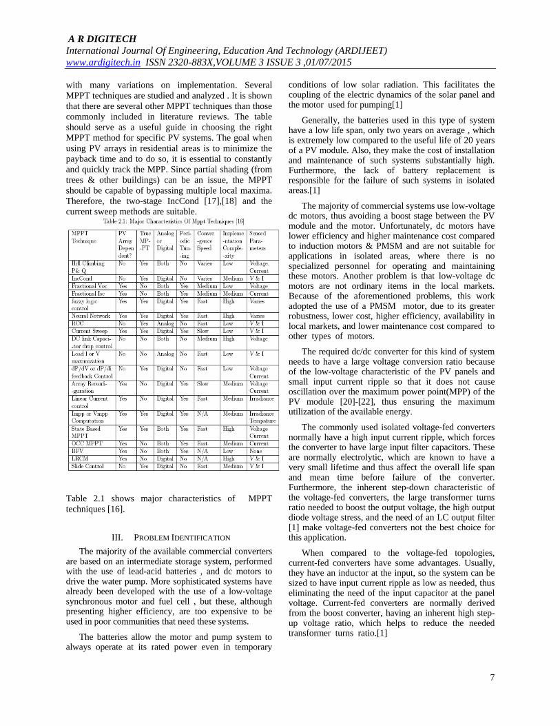
with many variations on implementation. Several MPPT techniques are studied and analyzed . It is shown that there are several other MPPT techniques than those commonly included in literature reviews. The table should serve as a useful guide in choosing the right MPPT method for specific PV systems. The goal when using PV arrays in residential areas is to minimize the payback time and to do so, it is essential to constantly and quickly track the MPP. Since partial shading (from trees & other buildings) can be an issue, the MPPT should be capable of bypassing multiple local maxima. Therefore, the two-stage IncCond [17],[18] and the current sweep methods are suitable.
Table 2.1 shows major characteristics of MPPT techniques [16].
III. PROBLEM IDENTIFICATION
The majority of the available commercial converters are based on an intermediate storage system, performed with the use of lead-acid batteries , and dc motors to drive the water pump. More sophisticated systems have already been developed with the use of a low-voltage synchronous motor and fuel cell , but these, although presenting higher efficiency, are too expensive to be used in poor communities that need these systems.
The batteries allow the motor and pump system to always operate at its rated power even in temporary
conditions of low solar radiation. This facilitates the coupling of the electric dynamics of the solar panel and the motor used for pumping[1]
Generally, the batteries used in this type of system have a low life span, only two years on average , which is extremely low compared to the useful life of 20 years of a PV module. Also, they make the cost of installation and maintenance of such systems substantially high. Furthermore, the lack of battery replacement is responsible for the failure of such systems in isolated areas.[1]
The majority of commercial systems use low-voltage dc motors, thus avoiding a boost stage between the PV module and the motor. Unfortunately, dc motors have lower efficiency and higher maintenance cost compared to induction motors & PMSM and are not suitable for applications in isolated areas, where there is no specialized personnel for operating and maintaining these motors. Another problem is that low-voltage dc motors are not ordinary items in the local markets. Because of the aforementioned problems, this work adopted the use of a PMSM motor, due to its greater robustness, lower cost, higher efficiency, availability in local markets, and lower maintenance cost compared to other types of motors.
The required dc/dc converter for this kind of system needs to have a large voltage conversion ratio because of the low-voltage characteristic of the PV panels and small input current ripple so that it does not cause oscillation over the maximum power point(MPP) of the PV module [20]-[22], thus ensuring the maximum utilization of the available energy.
The commonly used isolated voltage-fed converters normally have a high input current ripple, which forces the converter to have large input filter capacitors. These are normally electrolytic, which are known to have a very small lifetime and thus affect the overall life span and mean time before failure of the converter. Furthermore, the inherent step-down characteristic of the voltage-fed converters, the large transformer turns ratio needed to boost the output voltage, the high output diode voltage stress, and the need of an LC output filter [1] make voltage-fed converters not the best choice for this application.
When compared to the voltage-fed topologies, current-fed converters have some advantages. Usually, they have an inductor at the input, so the system can be sized to have input current ripple as low as needed, thus eliminating the need of the input capacitor at the panel voltage. Current-fed converters are normally derived from the boost converter, having an inherent high step-up voltage ratio, which helps to reduce the needed transformer turns ratio.[1]
A R DIGITECH International Journal Of Engineering, Education And Technology (ARDIJEET) www.ardigitech.in ISSN 2320-883X,VOLUME 3 ISSUE 3 ,01/07/2015
8
The design of a motor drive system powered directly from a PV source demands creative solutions to face the challenge of operating under variable power restrictions and still maximize the energy produced by the module and the amount of water pumped.
These requirements demand the use of a converter with the following features: high efficiency-due to the low energy available; low cost-to enable its deployment where it is most needed; autonomous operation-no specific training needed to operate the system; robustness-minimum amount of maintenance possible; and high life span-comparable to the usable life of 20 years of a PV panel.[1]
The use of a PMSM Motor presents a better solution to the commercial dc motor water pumping system. The development is oriented to achieve a more efficient, reliable, maintenance-free, and cheaper solution than the standard ones that use dc motors or low-voltage synchronous motors. The developed system is based on a current-fed multiresonant converter also known as resonant two-inductor boost converter.
From above discussion it has been identified that problems are as follows.
1. The batteries used in this type of system have a low life span,the lack of battery replacement is responsible for the failure of such systems in isolated areas,further they require periodic maintenance.
2. Low-voltage synchronous motor and DC motor are costly and require maintenance respectively,again they are not rarely available in market.
3. Commonly used isolated voltage-fed converters need large input filter capacitors which are normally electrolytic & LC output filter whose lifespan is small.
IV. SCOPE OF WORK
In the section 3 problem is identified which demands the use of a converter with the following features:
high efficiency-due to the low energy available;
low cost-to enable its deployment where it is most needed
autonomous operation-no specific training needed to operate the system;
robustness-minimum amount of maintenance possible; and high life span-comparable to the usable life of 20 years of a PV panel
Now aim of report is to develop an autonomous and fractional power (0-2hp) PMSM motor drive system. It will be supplied from a single photovoltaic panel, and
will be responsible to drive system without using any electrical energy storage device. So Nevertheless it must fulfill some specifications and functionalities as described below:[19]
High efficiency power processing to ensure effective input voltage (panel voltage) step up along the whole operational range;
Motor start up and shut down must be a function of: sun light, on/off button and water storage tank level (NO/NC contact);
Effective PMSM motor control to ensure that maximum available power is transferred from panel to a mechanical pump;
Safety conditions to allow panel cleaning procedure; Comparison with solutions based on another technologies
A. System Overview
This report proposes a new dc/dc converter and control suitable for PV water pumping and treatment that fulfill most of the aforementioned features. To ensure low cost and accessibility of the proposed system, it was designed to use a single PV module. The system should be able to drive low-power water pumps, in the range of 1/3 hp, more than enough to supply water for a family. The energy produced by the panel is fed to the motor through a converter with two power stages: a dc/dc two-inductor boost converter (TIBC) stage to boost the voltage of the panels and a dc/ac three-phase inverter to convert the dc voltage to three-phase ac voltage. The inverter is based on a classic topology (three legs, with two switches per leg) and uses a sinusoidal pulse width modulation (PWM) (SPWM) strategy with 1/6 optimal third harmonic voltage injection as proposed.[23] The use of this PWM strategy is to improve the output voltage level as compared to sinusoidal PWM modulation. This is a usual topology, and further analyses on this topology are not necessary. For the prototype used to verify the proposed system, a careful selection of the voltage source inverter (VSI) components is more than enough to guarantee the efficiency and cost requirements.
The required dc/dc converter for this kind of system needs to have a large voltage conversion ratio because of the low-voltage characteristic of the PV panels and small input current ripple so that it does not cause oscillation over the maximum power point (MPP) of the PV module,[20],[22] thus ensuring the maximum utilization of the available energy. When compared to the voltage-fed topologies, current-fed converters have some advantages. Usually, they have an inductor at the input, so the system can be sized to have input current ripple as low as needed, thus eliminating the need of the
A R DIGITECH International Journal Of Engineering, Education And Technology (ARDIJEET) www.ardigitech.in ISSN 2320-883X,VOLUME 3 ISSUE 3 ,01/07/2015
9
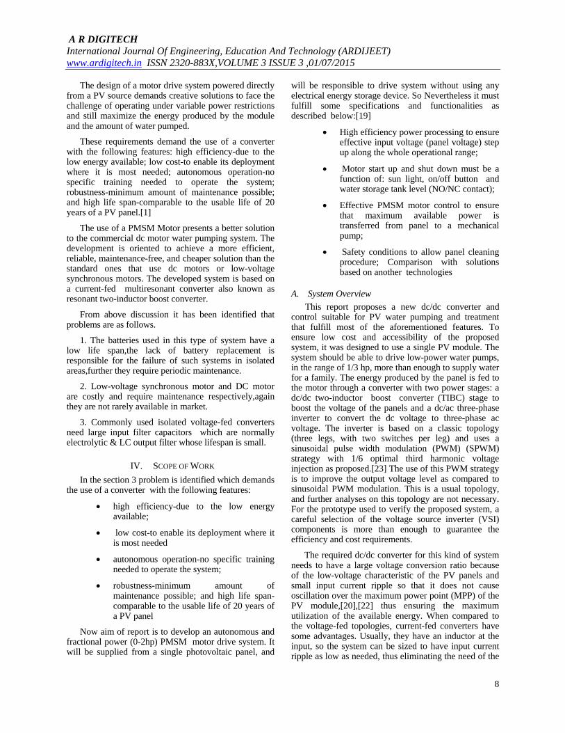
input capacitor at the panel voltage. Current-fed converters are normally derived from the boost converter, having an inherent high step-up voltage ratio, which helps to reduce the needed transformer turns ratio. The classical topologies of this kind are the current-fed push-pull converter[24][25],the current-fed full-bridge[26] , and the dual half-bridge converter.[ 27]. Although the current-fed topologies have all the aforementioned advantages , they still have problems with high voltage spikes created due to the leakage inductance of the transformers and with high voltage stress on the rectifying diodes[28]. Fig.4.1 presents an overview of the proposed system. One of the solutions to the current-fed PWM converters is the use of resonant topologies able to utilize the component parasitic characteristics, such as the leakage inductance and winding capacitance of transformers, in a productive way to achieve zero current switching (ZCS) or zero voltage switching (ZVS) condition to the active switches and rectifying diodes[29].
In this section, the use of a modified TIBC for the first-stage dc/dc converter is proposed, due to its very small number of components, simplicity, high efficiency, easy transformer flux balance[30],[31] , and common ground gate driving for both switches. These features make it the ideal choice for achieving the system’s necessary characteristics. Aside from the high dc voltage gain of the TIBC, it also compares favorably with other current-fed converters concerning switch voltage stress, conduction losses, and transformer utilization[32],[33]. In addition, the input current is distributed through the two boost inductors having its current ripple amplitude halved at twice the PWM frequency. This last feature minimizes the oscillations at the PV module operation point and makes it easier to achieve the MPP.
In its classical implementation, the TIBC is a hard-switched overlapped pulse-modulated converter; this way, at least one of the switches is always closed,
creating a conduction path for the input inductor current. Nevertheless, the TIBC can be modified to a multiresonant converter by adding a capacitor at the transformer’s secondary winding[33][34]. A multiresonant tank is formed by the magnetizing inductance of the transformer, its leakage inductance, and the added capacitor.
B. Cost Calculations For Solar Pumping System
Cost Calculation Consideration may vary as per
Market Available Rate.
1. Cost of PV panel is at Rs 56/Wp
2. There is provision like landing space of staircase to keep the ground floor top tank. Hence no additional civil construction is required for this purpose
3. Tank cost is taken as (Rs) 11/L.
4. Additional cost of Rs 2000/- is taken for miscellaneous expense.
Nowadays, there are reports of more efficient converters. During the design of the proposed converter, some compromises were made to achieve high efficiency and low cost. The semiconductor components were preferably cheaper than efficient since they are the most expensive components of the converter. Also, the magnetic components were handmade, although in the cost calculation, commercial prices were used fig 4.2 presents the distribution of costs of the entire system and of the prototype. .
A R DIGITECH International Journal Of Engineering, Education And Technology (ARDIJEET) www.ardigitech.in ISSN 2320-883X,VOLUME 3 ISSUE 3 ,01/07/2015
10
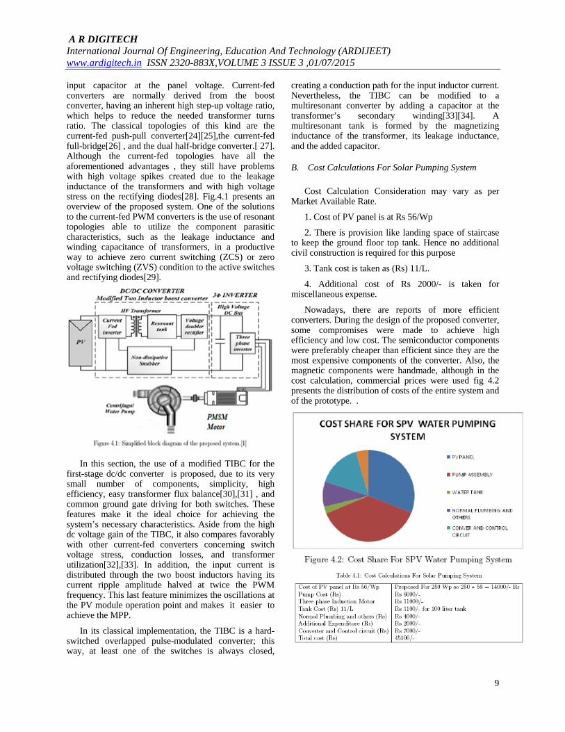
From fig 4.2, it can be seen that the converter takes only a small share (approximately 15 percent) of the overall system cost. Fig.4.3 shows the price distribution of the converter itself. The overall price of the prototype may be Rs 45000/- for single unit manufacturing . cost can be lowered by mass scale production table 4.1 shows cost calculations for solar pumping system
C. Scope of Work
In this report proposal of implementation of existing solar water pumping system to achieve high-efficiency, high-lifetime, and low-cost converter for agriculture and rural application will be done.
The scope of work would be for further modification using high efficient solar cell ,which will reduce size of the prototype , again by using thermal energy of solar panel in combination with molten salt technology we can drive pump at time when sun is not available.this may be new type of an autonomous photovoltaic water pumping system.
V. SIMULATION & RESULT
Fig.4.1 shows schematic diagram for the stand-alone solar PV based PMSM drive for water pumping system. The proposed system consists of solar PV panel, a TIBC converter, a three phase VSI (Voltage Source Inverter)and a PMSM coupled with a centrifugal water pump. A PV or solar cell is the basic building block of a PV system. An individual PV cell is usually quite small, typically producing about 1 or 2W of power. To increase the power output of PV cells, these cells are connected in series and parallel to assemble larger unit called PV module. The PV array is connected to the DC to DC boost converter to increase the output voltage level. An MOSFET based VSI is used for DC to AC conversion and connected to the PMSM drive. The constant DC voltage is converted to the AC output using a VSI. Reference speed of PMSM is a function of solar irradiation.
A. PV Cell Simulation and MPPT Control
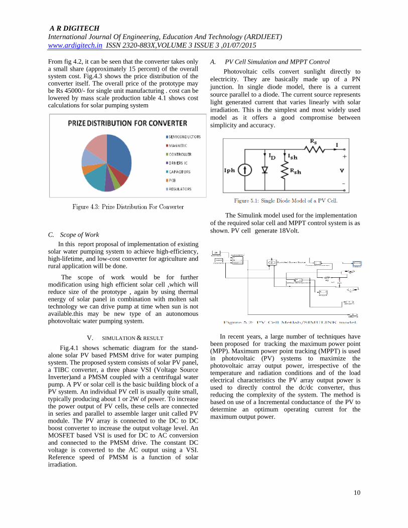
Photovoltaic cells convert sunlight directly to electricity. They are basically made up of a PN junction. In single diode model, there is a current source parallel to a diode. The current source represents light generated current that varies linearly with solar irradiation. This is the simplest and most widely used model as it offers a good compromise between simplicity and accuracy.
The Simulink model used for the implementation of the required solar cell and MPPT control system is as shown. PV cell generate 18Volt.
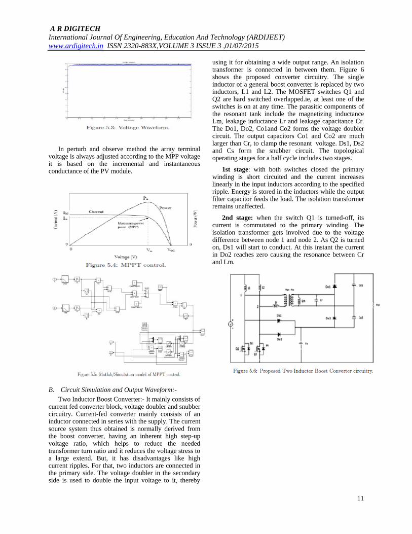
In recent years, a large number of techniques have been proposed for tracking the maximum power point (MPP). Maximum power point tracking (MPPT) is used in photovoltaic (PV) systems to maximize the photovoltaic array output power, irrespective of the temperature and radiation conditions and of the load electrical characteristics the PV array output power is used to directly control the dc/dc converter, thus reducing the complexity of the system. The method is based on use of a Incremental conductance of the PV to determine an optimum operating current for the maximum output power.
A R DIGITECH International Journal Of Engineering, Education And Technology (ARDIJEET) www.ardigitech.in ISSN 2320-883X,VOLUME 3 ISSUE 3 ,01/07/2015
11
In perturb and observe method the array terminal voltage is always adjusted according to the MPP voltage it is based on the incremental and instantaneous conductance of the PV module.
B. Circuit Simulation and Output Waveform:-
Two Inductor Boost Converter:- It mainly consists of current fed converter block, voltage doubler and snubber circuitry. Current-fed converter mainly consists of an inductor connected in series with the supply. The current source system thus obtained is normally derived from the boost converter, having an inherent high step-up voltage ratio, which helps to reduce the needed transformer turn ratio and it reduces the voltage stress to a large extend. But, it has disadvantages like high current ripples. For that, two inductors are connected in the primary side. The voltage doubler in the secondary side is used to double the input voltage to it, thereby
using it for obtaining a wide output range. An isolation transformer is connected in between them. Figure 6 shows the proposed converter circuitry. The single inductor of a general boost converter is replaced by two inductors, L1 and L2. The MOSFET switches Q1 and Q2 are hard switched overlapped.ie, at least one of the switches is on at any time. The parasitic components of the resonant tank include the magnetizing inductance Lm, leakage inductance Lr and leakage capacitance Cr. The Do1, Do2, Co1and Co2 forms the voltage doubler circuit. The output capacitors Co1 and Co2 are much larger than Cr, to clamp the resonant voltage. Ds1, Ds2 and Cs form the snubber circuit. The topological operating stages for a half cycle includes two stages.
1st stage: with both switches closed the primary winding is short circuited and the current increases linearly in the input inductors according to the specified ripple. Energy is stored in the inductors while the output filter capacitor feeds the load. The isolation transformer remains unaffected.
2nd stage: when the switch Q1 is turned-off, its current is commutated to the primary winding. The isolation transformer gets involved due to the voltage difference between node 1 and node 2. As Q2 is turned on, Ds1 will start to conduct. At this instant the current in Do2 reaches zero causing the resonance between Cr and Lm.
A R DIGITECH International Journal Of Engineering, Education And Technology (ARDIJEET) www.ardigitech.in ISSN 2320-883X,VOLUME 3 ISSUE 3 ,01/07/2015
12
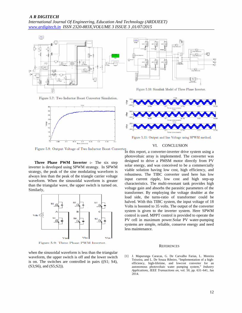
Three Phase PWM Inverter :- The six step inverter is developed using SPWM strategy. In SPWM strategy, the peak of the sine modulating waveform is always less than the peak of the triangle carrier voltage waveform. When the sinusoidal waveform is greater than the triangular wave, the upper switch is turned on. Similarly,
when the sinusoidal waveform is less than the triangular waveform, the upper switch is off and the lower switch is on. The switches are controlled in pairs ((S1; S4), (S3;S6), and (S5;S2)).
VI. CONCLUSION
In this report, a converter-inverter drive system using a photovoltaic array is implemented. The converter was designed to drive a PMSM motor directly from PV solar energy, and was conceived to be a commercially viable solution having low cost, high efficiency, and robustness. The TIBC converter used here has low input current ripple, low cost and high step-up characteristics. The multi-resonant tank provides high voltage gain and absorbs the parasitic parameters of the transformer. By employing the voltage doubler at the load side, the turns-ratio of transformer could be halved. With this TIBC system, the input voltage of 18 Volts is boosted to 35 volts. The output of the converter system is given to the inverter system. Here SPWM control is used. MPPT control is provided to operate the PV cell in maximum power.Solar PV water-pumping systems are simple, reliable, conserve energy and need less maintenance.
REFERENCES
[1] J. Mapurunga Caracas, G. De Carvalho Farias, L. Moreira
Teixeira, and L. De Souza Ribeiro, “Implementation of a high-efficiency, high-lifetime, and lowcost converter for an autonomous photovoltaic water pumping system,” Industry Applications, IEEE Transactions on, vol. 50, pp. 631–641, Jan 2014.
A R DIGITECH International Journal Of Engineering, Education And Technology (ARDIJEET) www.ardigitech.in ISSN 2320-883X,VOLUME 3 ISSUE 3 ,01/07/2015
13
[2] akihiro oi, “Design and simulation of photovoltaic water pumping system,” thesis presented to the faculty of California polytechnic state university san luis obispo, Jan 2005.
[3] M. Maupoux, Solar PV Water pumping. Practical Action, The Schumacher Centre, Bourton on Dunsmore, Rugby, Warwickshire, CV23 9QZ, UK, 2010.
[4] A. Doig, Solar Photovoltaic energy. Practical Action, The Schumacher Centre, Bourton on Dunsmore, Rugby, Warwickshire, CV23 9QZ, UK, April 2012.
[5] M. Vitorino, M. Beltrao de Rossiter Correa, C. Jacobina, and A. Lima, “An effective induction motor control for photovoltaic pumping,” Industrial Electronics, IEEE Transactions on, vol. 58, pp. 1162–1170, April 2011.
[6] A. B. C. S. B. Slama and A. Chrif, “Efficient design of a hybrid (pv-fc) water pumping system with separate mppt control algorithm,” IJCSNS International Journal of Computer Science and Network Security, vol. 12, pp. 53–60, January 2012.
[7] E. Muljadi and R. Taylor, “Pv water pumping with a peak power tracker using a simple six step square wave inverter,” Industry Applications Conference, vol. 1, pp. 133–142, October 1996.
[8] G. Terorde, K. Hameyer, and R. Belmans, “Sensorless control of a permanent magnet synchronous motor for pv-powered water pump systems using the extended kalman filter,” in Electrical Machines and Drives, 1999. Ninth International Conference on (Conf. Publ. No. 468), pp. 366–370, 1999.
[9] J. Arribas and C. Gonzalez, “Optimal vector control of pumping and ventilation induction motor drives,” Industrial Electronics, IEEE Transactions on, vol. 49, pp. 889–895, Aug 2002.
[10] R. Chacko, B. Sreekumari, K. Fathima, and Z. Lakaparampil, “High performance ac drive for solar pumps,” in Industrial Technology 2000. Proceedings of IEEE Interna- tional Conference on, vol. 1, pp. 600–605 vol.2, Jan 2000.
[11] D. Snyman and J. Enslin, “Combined low-cost, high-efficient inverter, peak power tracker and regulator for pv applications,” in Power Electronics Specialists Confer- ence, 1989. PESC '89 Record., 20th Annual IEEE, pp. 67–74 vol.1, Jun 1989.
[12] I. J. H. R. Enslin, Member and I. D. B. Snyman, Member, “Combined low-cost , high-efficient inverter, peak power tracker and regulator for pv applications,” IEEE TRANSACTIONS ON POWER ELECTRONICS, vol. 6, pp. 73–83, Jan 1991.
[13] N. Barsoum, “Implementation of a prototype for a traditional solar tracking system,” in Computer Modeling and Simulation, 2009. EMS '09. Third UKSim European Symposium on, pp. 23–30, Nov 2009.
[14] P.Andrada and J.Castro, “Solar photovoltaic water pumping system using a new linear actuator,” in GAECE, Drives Group Electronically Commutated UPC Depart- ment of Electrical Engineering , Engineering EPS Vilanova Avenue Victor Balagues /n, 08800.
[15] M. Dubey, S. Sharma, and R. Saxena, “Solar pv stand-alone water pumping system employing pmsm drive,” in Electrical, Electronics and Computer Science (SCEECS), 2014 IEEE Students' Conference on, pp. 1–6, March 2014.
[16] T. Esram and P. Chapman, “Comparison of photovoltaic array maximum power point tracking techniques,” Energy Conversion, IEEE Transactions on, vol. 22, pp. 439–449, June 2007.
[17] K. Irisawa, T. Saito, I. Takano, and Y. Sawada, “Maximum power point tracking control of photovoltaic generation system under non-uniform insolation by means of monitoring cells,” in Photovoltaic Specialists Conference, 2000. Conference Record of the Twenty-Eighth IEEE, pp. 1707–1710, 2000.
[18] K. Kobayashi, I. Takano, and Y. Sawada, “A study on a two stage maximum power point tracking control of a photovoltaic system under partially shaded insolation conditions,” in Power Engineering Society General Meeting, 2003, IEEE, vol. 4, pp. –2617 Vol. 4, July 2003.
[19] M. B. R. C. M. Chunting and J. O. P. Pinto, “The ieee 2011 international future energy challenge-request for proposals,” In Proc. IFEC, 2010.
[20] M. Cacciato, A. Consoli, and V. Crisafulli, “A high voltage gain dc/dc converter for energy harvesting in single module photovoltaic applications,” in Industrial Elec- tronics (ISIE), 2010 IEEE International Symposium on, pp. 550–555, July 2010.
[21] P. Wolfs, “A current-sourced dc-dc converter derived via the duality principle from the half-bridge converter,” Industrial Electronics, IEEE Transactions on, vol. 40, pp. 139–144, Feb 1993.
[22] P.Wolfs and Q. Li, “An analysis of a resonant half bridge dual converter operating in continuous and discontinuous modes,” in Power Electronics Specialists Conference, 2002. pesc 02. 2002 IEEE 33rd Annual, vol. 3, pp. 1313–1318 vol.3, 2002.
[23] S. Bowes and A. Midoun, “Suboptimal switching strategies for microprocessorcontrolled pwm inverter drives,” Electric Power Applications, IEE Proceedings B, vol. 132, pp. 133–148, May 1985.
[24] T.-J. Liang, R.-Y. Chen, J.-F. Chen, and W.-J. Tzeng, “Buck-type current-fed pushpull converter with zcs for high voltage applications,” in TENCON 2007 - 2007 IEEE Region 10 Conference, pp. 1–4, Oct 2007.
[25] P. Mantovanelli and I. Barbi, “A new current-fed, isolated pwm dc-dc converter,” Power Electronics, IEEE Transactions on, vol. 11, pp. 431–438, May 1996.
[26] R.-Y. Chen, T.-J. Liang, J.-F. Chen, R.-L. Lin, and K.-C. Tseng, “Study and implementation of a current-fed full-bridge boost dc x2013;dc converter with zero-current switching for high-voltage applications,” Industry Applications, IEEE Transactions on, vol. 44, pp. 1218–1226, July 2008.
[27] J. Kim, H.-S. Song, and K. Nam, “Asymmetric duty control of a dual-half-bridge dc/dc converter for single-phase distributed generators,” Power Electronics, IEEE Transactions on, vol. 26, pp. 973–982, March 2011.
[28] B. Liu, C. Liang, and S. Duan, “Design considerations and topology selection for dc-module-based building integrated photovoltaic system,” in Industrial Electronics and Applications, 2008. ICIEA 2008. 3rd IEEE Conference on, pp. 1066–1070, June 2008.
[29] J. Biela and J. Kolar, “Using transformer parasitics for resonant converters - a review of the calculation of the stray capacitance of transformers,” in Industry Applications Conference, 2005. Fourtieth IAS Annual Meeting. Conference Record of the 2005, vol. 3, pp. 1868–1875 Vol. 3, Oct 2005.
[30] L. Yan and B. Lehman, “Isolated two-inductor boost converter with one magnetic core,” in Applied Power Electronics Conference and Exposition, 2003. APEC '03. Eighteenth Annual IEEE, vol. 2, pp. 879–885 vol.2, Feb 2003.
[31] Y. Jang, “Two-boost converter,” tech. rep., U.S. Patent 6 239 584, May 29 2001.
[32] Q. Li and P. Wolfs, “The power loss optimization of a current fed zvs two-inductorboost converter with a resonant transition gate drive,” Power Electronics, IEEE Transactions on, vol. 21, pp. 1253–1263, Sept 2006.
[33] W. de Aragao Filho and I. Barbi, “A comparison between two current-fed pushpull dc-dc converters-analysis, design and experimentation,” in Telecommunications Energy Conference, 1996. INTELEC '96., 18th International, pp. 313–320, Oct 1996.

A R DIGITECH International Journal Of Engineering, Education And Technology (ARDIJEET) www.ardigitech.in ISSN 2320-883X,VOLUME 3 ISSUE 3 ,01/07/2015
14
[34] B. Yuan, X. Yang, X. Zeng, J. Duan, J. Zhai, and D. Li, “Analysis and design of a high step-up current-fed multiresonant dc x2013;dc converter with low circulating
energy and zero-current switching for all active switches,” Industrial Electronics, IEEE Transactions on, vol. 59, pp. 964–978, Feb 2012.


![Crow Search Optimized Control of Photovoltaic …A DC -DC converter [6], buck boost converter [7], Luo converter [8], canonical switching cell (CSC) converter [9], zeta converter [10]](https://img.pdfslide.net/doc/110x75/5fcf5114fee703425c72d389/crow-search-optimized-control-of-photovoltaic-a-dc-dc-converter-6-buck-boost.jpg)