Embed Size (px)
Citation preview


G R AH AM P A Y N E
Microwave ‘Engineer’ ??
• 1966 – 1983 Philips Research Labs Microwave Engineer
• 1983 – 1999 Hewlett-Packard Ltd. Microwave Applications Engineer
• 1999 – 2007 Agilent Technologies Consultant Microwave Engineer

True, Dedicated Microwave Engineer !
• 1966 – 1983 Philips Research Labs Microwave Engineer
• 1983 – 1999 Hewlett-Packard Ltd. Microwave Applications Engineer
• 1999 – 2007 Agilent Technologies Consultant Microwave Engineer

Historical Development
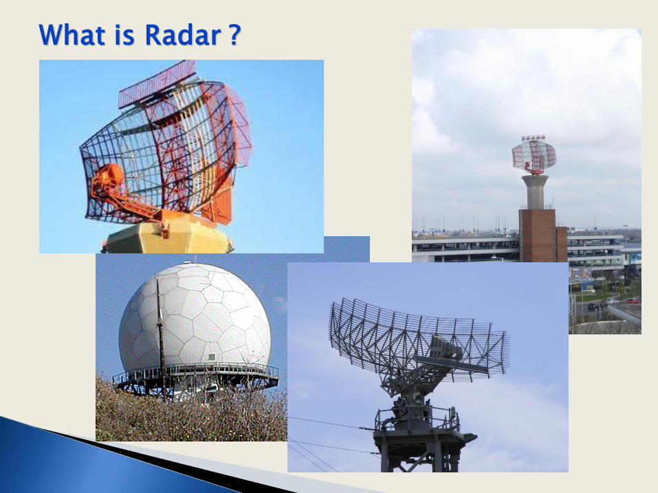
What is Radar?
Radar Types
Radar Antennas
Civilian Radars
Military Radars
Future

Radio Detection And Ranging
◦ Called RDF – Radio detection and Ranging by the British
◦ Renamed RADAR by the Americans in 1940

PULSED RADAR BASIC PRINCIPLE
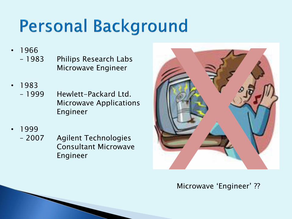
Early Evolution – Bats! ◦ Bats use very similar techniques to modern radar
Doppler
Monopulse
PRF Agility
Chirped signals etc
But, non electronic !

QUIZ
Question 1 When was the first demonstration
of a practical radar system

1904
Christian Huelsmeyer
Telemobiloscope
Anti Ship Collision Device Range 3000m Freq ~ 700 MHz

1922/23 Guglielmo Marconi showed his first working device
1925/1926 Breit & Tuve, Appleton & Barnett measured Earth’s
ionosphere using a pulsed technique.
1930 US Engineers saw radar like effect at landing strip
1928 First UK Patent by HM Signal school by L. S. Alder
1922/1930 Page demonstrates the world’s first pulsed radar system
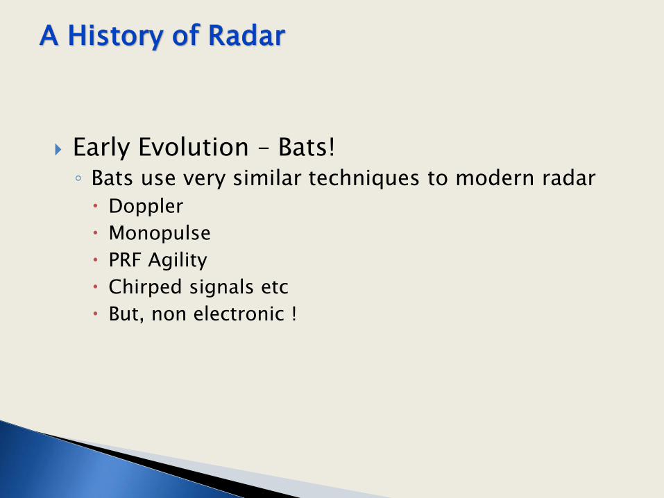
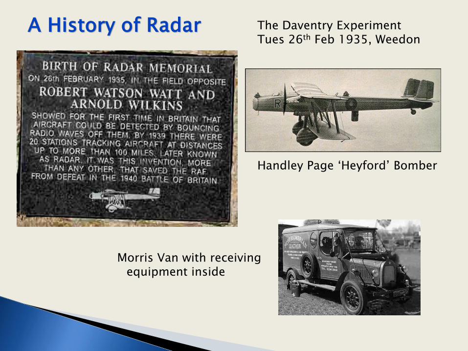
1935 Watson-Watt and Arnold Wilkens demonstrated successful detection of aircraft – the so called ‘Daventry Experiment’
The Daventry Experiment Tues 26th Feb 1935, Weedon
Handley Page ‘Heyford’ Bomber
Morris Van with receiving equipment inside

The Daventry Experiment Tues 26th Feb 1935, Weedon
Wilkins’s original lab book sketch

1922/23 Guglielmo Marconi showed his first working device
1925/1926 Breit & Tuve, Appleton & Barnett measured Earth’s
ionosphere using a pulsed technique.
1930 US Engineers saw radar effect at landing strip
1928 First UK Patent by HM Signal school by L. S. Alder
1930 Page demonstrates the world’s first pulsed radar system
1935 Watson-Watt and Arnold Wilkens demonstrated successful detection of aircraft – the so called ‘Daventry Experiment’
1939/45 Development of Chain Home stations
1940 Refinement of Magnetron by Randall & Boot
1940 – Jamming, Stealth, Passive Radar, SAR, Phased Arrays etc

•Battle of Britain • Chain Home
• Chain Home Low/Extra Low
•Refinement of the Magnetron •H2S and Centimetric Radar •Wurzburg & Bruneval Raid • Invention of ‘Chaff’ or ‘Window’
Key Developments

Problem • France is only 22 miles from the South Coast of England
• Aircraft flying at 300 mph will cross in about 7 minutes
• The only warning system that was practical was the eyes and ears
or the Royal Observer Corps
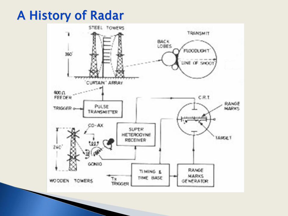
Solution The ‘Chain Home’ Radar Stations

Chain Home Radar • Worked at 20 and 70 MHz
• TX Antennas 360 feet high steel masts
• RX Antennae were smaller and used
crossed dipoles
• Stations deployed around the coast of UK mainly in the South and East
• Furthest south was Ventnor on the IOW, which opened on Jan 1939. By Easter 1939 all the initial 20 CH were operational
• Stations were attacked many times but rebuilt quickly.

Unable to detect low flying aircraft due to ‘clutter’

Chain Home Low
• Worked at 200 MHz
• Aircraft 500 feet up and 25 miles away could be detected + 100 mile range at 10,000 ft altitude could be detected
• Much smaller footprint
• Originally built with separate Tx and Rx arrays manually rotated but later integrated into a single array
• Locally Truleigh Hill (CHL) and Poling (CH) worked in tandem feeding data to the Filter Room and Stanmore.

Chain Home Low
VT98 Power Triode Valve
• Each tube could deliver 100 kW at 200 MHz
• Force air cooling
The filament required 12.6V at 58A !

Chain Home Extra Low
• Worked at 3000 MHz (3 GHz)
• Peak Power 500 kWatt • Pulse length 0.6 or 1.9 uS
• Pulse rate 500 pulses/sec
• Nodding -1 to +20 degrees vertical
• Beam width 7.5 degrees
• Aircraft tracked at 50 ft out to 45 miles
Type 13 CHL Radar

Operation Biting – The Bruneval Raid
• Feb 1942 Combined Ops raid on Bruneval, Northern France
• 110 Para Commandos led by Maj John Frost
• Technicians dismantled the ‘Wurzburg’ radar and all returned to UK except for 2 killed and 6 captured
• Led to a greater understanding of German radar technology and capability
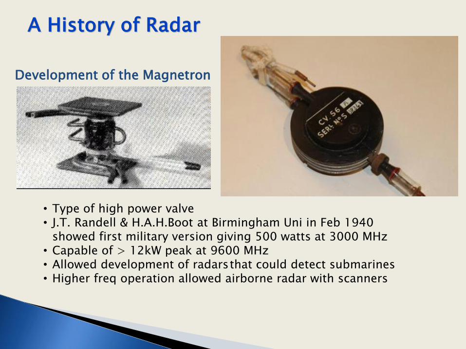
Development of the Magnetron
• Type of high power valve • J.T. Randell & H.A.H.Boot at Birmingham Uni in Feb 1940
showed first military version giving 500 watts at 3000 MHz • Capable of > 12kW peak at 9600 MHz • Allowed development of radars that could detect submarines • Higher freq operation allowed airborne radar with scanners
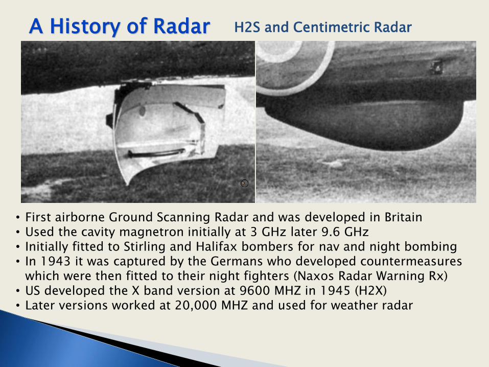
H2S and Centimetric Radar
• First airborne Ground Scanning Radar and was developed in Britain • Used the cavity magnetron initially at 3 GHz later 9.6 GHz • Initially fitted to Stirling and Halifax bombers for nav and night bombing • In 1943 it was captured by the Germans who developed countermeasures
which were then fitted to their night fighters (Naxos Radar Warning Rx) • US developed the X band version at 9600 MHZ in 1945 (H2X) • Later versions worked at 20,000 MHZ and used for weather radar

H2S and Centimetric Radar

‘Window ‘ or Chaff
• Directly developed Robert Cockburn of TRE as result of the Bruneval raid when it was discovered that only 3 frequencies were in use by Germans
• Black paper strip backed with aluminium foil - ½ wavelength long
• Foil acted as an antenna and re-radiated the enemy radar signal
Chaff deployed From this direction

Historical Development
What is Radar?
Radar Types
Radar Antennas
Civilian Radars
Military Radars
Future

PULSED RADAR BASIC PRINCIPLE

Radar Block Diagram

Radar Block Diagram

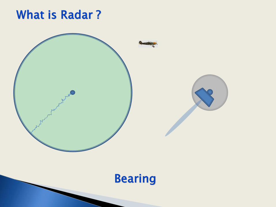
Key Questions:
o How far away is the target ? “Range” o In what direction is the target? “Bearing”
Speed can be calculated from:
Speed = Range/Time

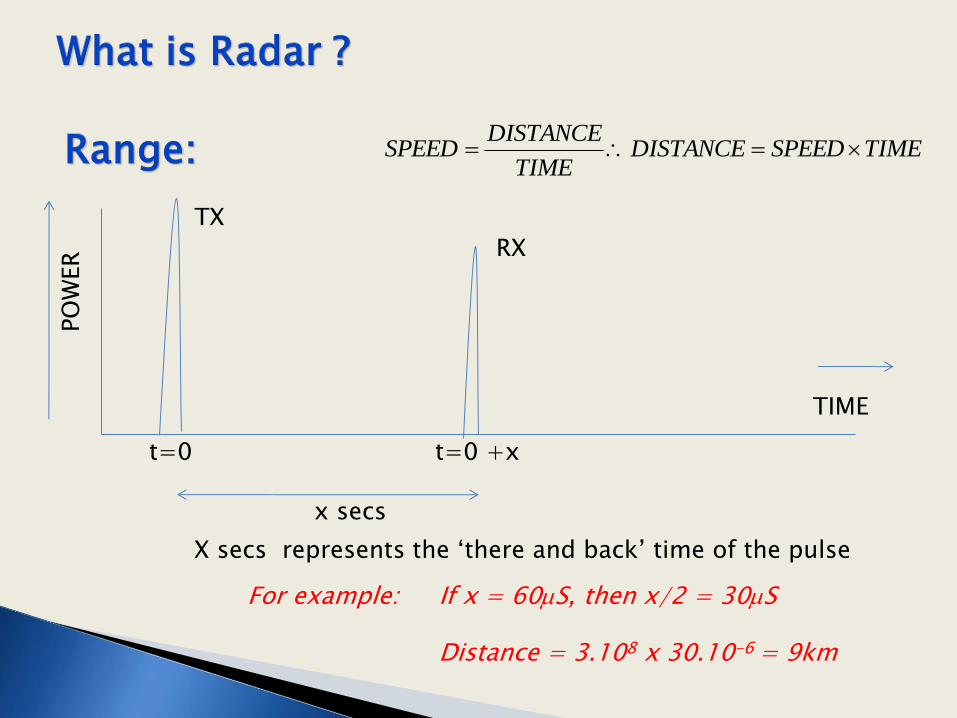
x secs
TIMESPEEDDISTANCETIME
DISTANCESPEED
X secs represents the ‘there and back’ time of the pulse
For example: If x = 60mS, then x/2 = 30mS Distance = 3.108 x 30.10-6 = 9km
TIME
PO
WER
TX
RX
t=0 t=0 +x


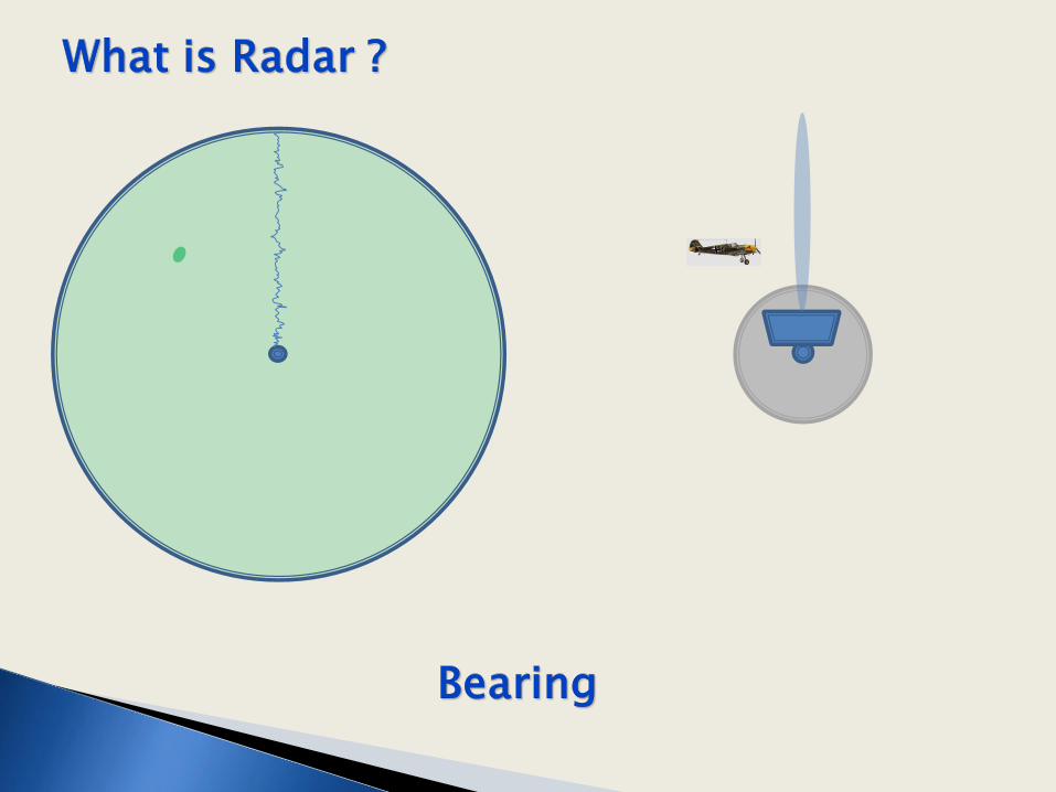
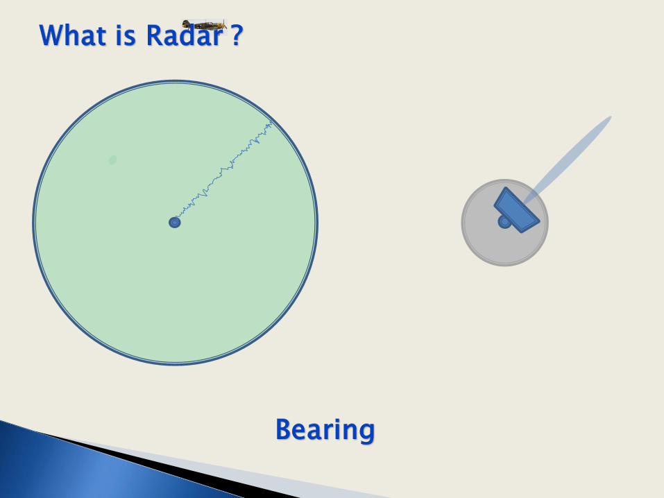
The angular distance of the target compared to some fixed datum e.g.
• The bearing of the target from nose of the aircraft or ship – Bearing Relative
• The bearing of the target from North - Bearing True


QUIZ
Question 2

TIME
PO
WER
TX
RX
t=0 t=0 +x
Remember this ?
TIMESPEEDDISTANCETIME
DISTANCESPEED

Historical Development
What is Radar?
Radar Types
Radar Antennas
Civilian Radars
Military Radars
Future

More gain and a narrower beam means more elements in the array !
YAGI Antenna

Early WW11 Experiments
Naval Research Labs 1937

Decca Radar 1963
Approach, Guidance and Weather Radar
Note the use of a parabolic type reflector


Remember these ‘golf balls’ just off the A171 to Whitby ??
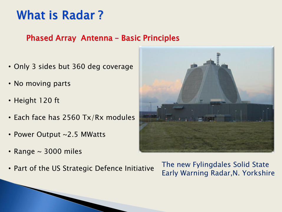
The new Fylingdales Solid State Early Warning Radar,N. Yorkshire
• Only 3 sides but 360 deg coverage • No moving parts • Height 120 ft • Each face has 2560 Tx/Rx modules • Power Output ~2.5 MWatts • Range ~ 3000 miles • Part of the US Strategic Defence Initiative
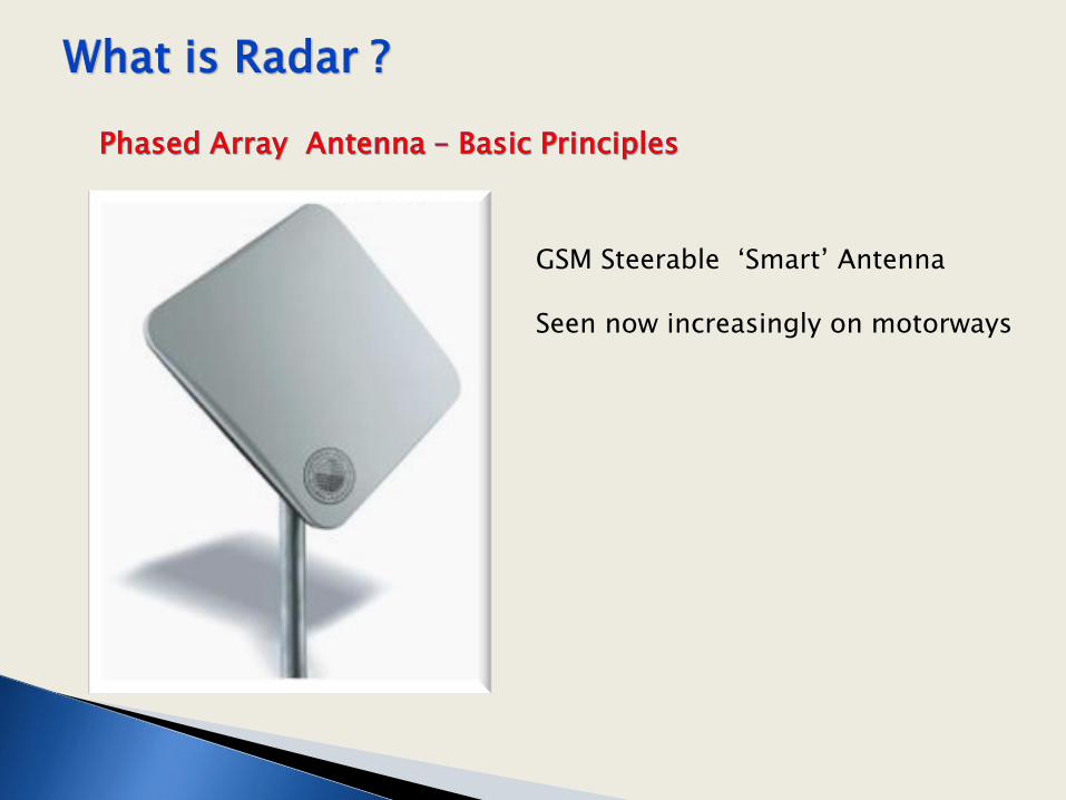
GSM Steerable ‘Smart’ Antenna Seen now increasingly on motorways

Two beams, steered so that they overlap
Sum of the two beam patterns
Difference of the two beam patterns
Ratio of the sum-difference patterns
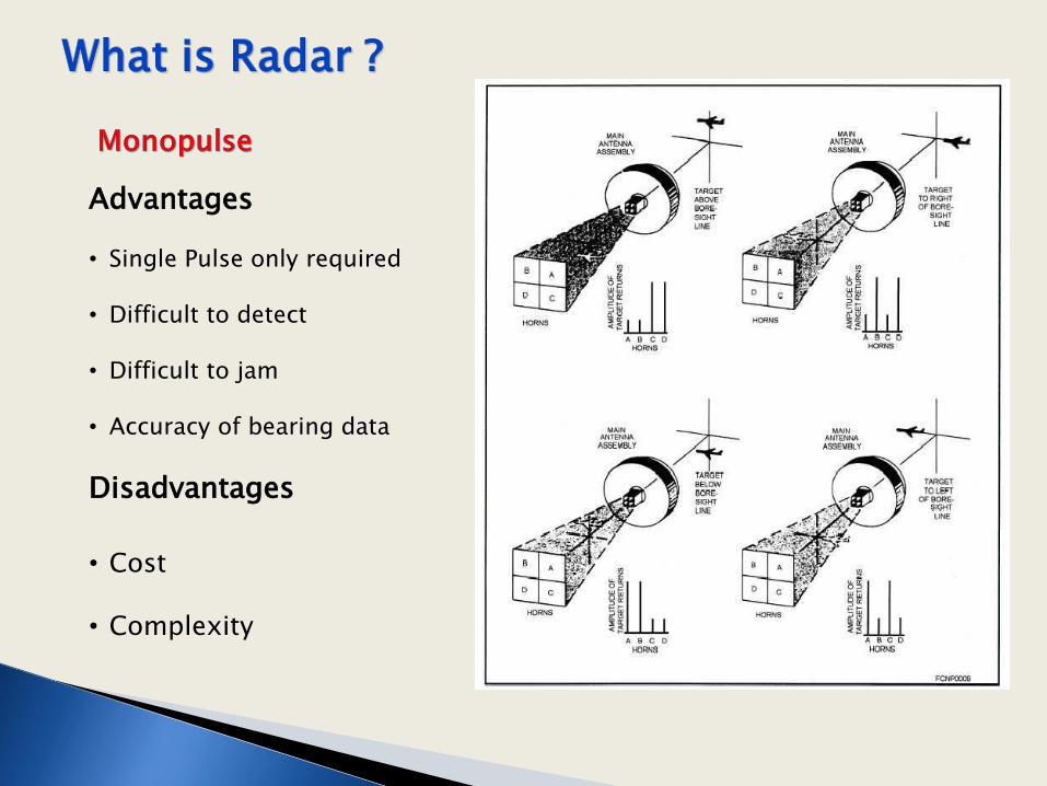
Advantages • Single Pulse only required
• Difficult to detect
• Difficult to jam
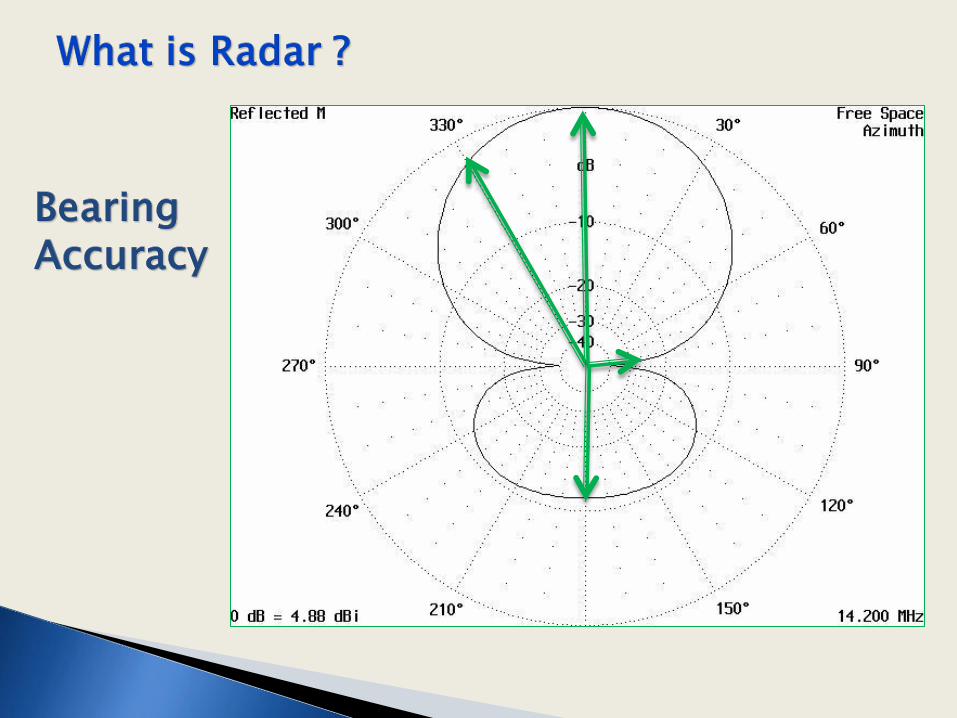
• Accuracy of bearing data
Disadvantages
• Cost
• Complexity

Modern 23cm (1.3 GHz)
Airport Radar
Heathrow Airport Surveillance Radar
Feed Point
Parabolic Reflector
?????

Modern 23cm (1.3 GHz)
Airport Radar
Heathrow Airport Surveillance Radar
Feed Point
Parabolic Reflector
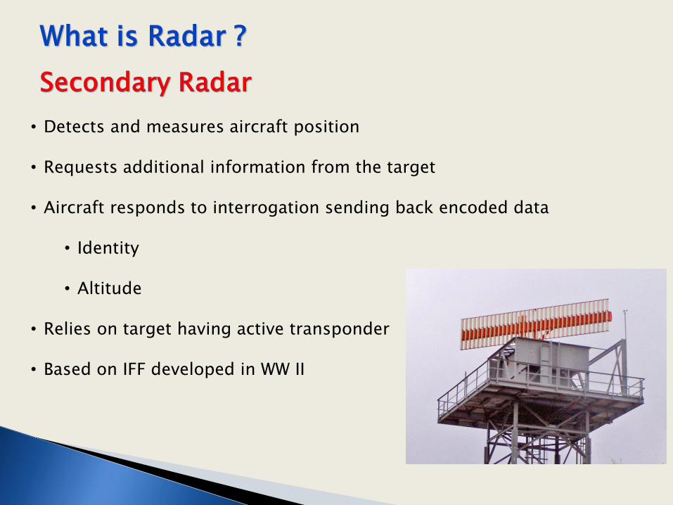
• Detects and measures aircraft position • Requests additional information from the target • Aircraft responds to interrogation sending back encoded data
• Identity • Altitude
• Relies on target having active transponder • Based on IFF developed in WW II
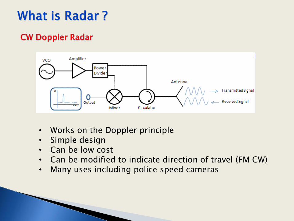
• Works on the Doppler principle • Simple design • Can be low cost • Can be modified to indicate direction of travel (FM CW) • Many uses including police speed cameras

• Shipborne – Naval and Civil • Weather - Balloon tracking and rainfall radars • Space Resource Mapping • Ground Penetrating Radar (GPR)
• Civil, Forensic, Archaeology, Mines etc
• Speed Checking – Police, Harbour Authorities etc • Ultrasonic
• Foetal checks • Sonar • Echo Sounders
• Automobile Anti-Collision using 67 GHz
• Traffic lights, Height Finding etc .. etc ..

ESA Envisat • Prime contractor Dornier Germany • Launched 2002 in a polar orbit • Provides measurements of
atmosphere, ocean, land and ice
• Advanced Synthetic Aperture Radar (SAR)
• Radar Altimeter

GPR principle
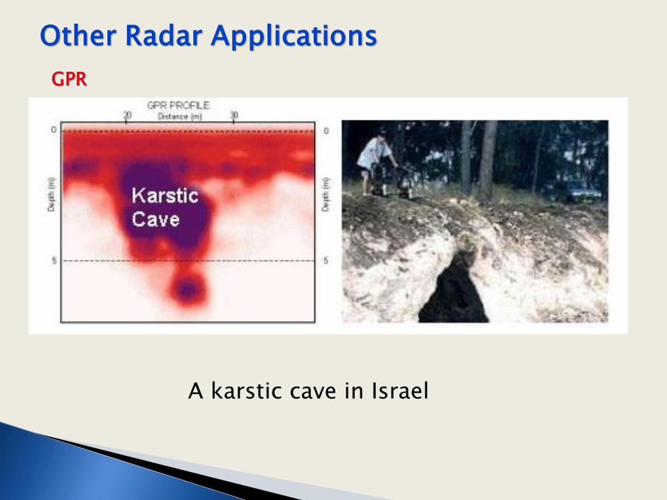
A karstic cave in Israel

Antennas operating at 150 MHz
• Uses pulsed radar techniques with heavy signal processing
• 8m depth resolution • > 4km depth

Operates in K Band ~ 24 GHz Accuracy < 2% based on photos compared to road markings Radar used to trigger camera and flash sequence when vehicle detected above a set speed limit

• Smaller, lighter hardware
• Extension of the use of digital signal processing
• Better 3D imaging e.g. 94 GHz FMCW at St Andrews Uni
• ‘Smart’ control of cars
• …. ??

What is 373.2 ??
FINALLY !

Blame John Wells for giving out false information !
376.73031346177… Ohms is the Impedance of Free Space
Most of us (ex) engineers are content with 377 ohms !
THANK YOU ALL FOR LISTENING