Embed Size (px)
Citation preview

Pub. 42004-352J
GAI-Tronics Corporation P.O. Box 1060, Reading, PA 19607-1060 USA610-777-1374 800-492-1212 Fax: 610-796-5954
VISIT WWW.GAI-TRONICS.COM FOR PRODUCT LITERATURE AND MANUALS
G A I - T R O N I C S ® C O R P O R A T I O NA H U B B E L L C O M P A N Y
Model 293-001, 293AL-001, 297-001,298-001, and 294AL-001 Emergency Phones
T A B L E O F C O N T E N T S
Getting Started ................................................................................................................................1Product Overview ................................................................................................................................... 1
Standard Operation ................................................................................................................................ 3Placing an Emergency Call ...................................................................................................................................3Placing a Non-Emergency Call (Models 294AL-001 and 298-001 Only)............................................................3
Americans with Disabilities Act (ADA) Functionality......................................................................... 4
Installation ......................................................................................................................................5Safety Guidelines..................................................................................................................................... 5
General Installation Guidelines ............................................................................................................. 5Tamper-Resistant Hardware .................................................................................................................................5Conduit Installation Details ..................................................................................................................................6
Models 293-001, 293AL-001, and 294AL-001....................................................................................... 7
Models 297-001 and 298-001 .................................................................................................................. 9
Setup ..............................................................................................................................................12Hardware Configuration...................................................................................................................... 12
Audio Level Adjustments ..................................................................................................................... 14
Programming ................................................................................................................................16Remote Programming .......................................................................................................................... 16
Local Programming .............................................................................................................................. 17
Programming Sequences ...................................................................................................................... 19Dialing Options...................................................................................................................................................19Password .............................................................................................................................................................21Silent Monitoring Feature ...................................................................................................................................21Off-Hook Ringing...............................................................................................................................................21Disconnect Options.............................................................................................................................................22Americans with Disabilities Act (ADA) Programming ......................................................................................23Automatic Line Level Compensation for Optimum Audio Performance ...........................................................23
Maintenance..................................................................................................................................25Specifications ................................................................................................................................26Confidentiality Notice ...................................................................................................................29

PUB. 42004-352J
GAI-Tronics Corporation P.O. Box 1060, Reading, PA 19607-1060 USA610-777-1374 800-492-1212 Fax: 610-796-5954
VISIT WWW.GAI-TRONICS.COM FOR PRODUCT LITERATURE AND MANUALS
Model 293-001, 293AL-001, 297-001,298-001, and 294AL-001 Emergency Phones
Getting StartedProduct OverviewThank-you for your purchase of a GAI-Tronics ADA-compliant emergency telephone. This manualapplies to the following GAI-Tronics ADA-Compliant Emergency Telephones:
Model Description
293-001 Emergency Phone – This phone is housed in a safety yellow, glass-reinforced polyesterenclosure that is designed to be surface-mounted and includes an emergency push button.
293AL-001 Emergency Phone – The vandal-resistant phone is housed in a cast aluminum enclosurepainted safety yellow that is designed to be surface-mounted and includes an emergencypush button.
294AL-001 Emergency Phone with Keypad – A cast aluminum enclosure painted safety yellow thatis designed to be surface-mounted and includes a 12-button Braille keypad, an emergencypush button and a call (off-hook) button.
297-001 Flush-panel Emergency Phone – This is a flush-mount phone with a heavy-gaugebrushed stainless steel front panel, and includes an emergency push button.
298-001 Flush-panel Emergency Phone with Keypad – This flush-mount phone with a heavy-gauge brushed stainless steel front panel includes a 12-button Braille keypad, anemergency push button, and a call (off-hook) button.
All of the emergency telephones listed above comply with the Americans with Disabilities Act (ADA).Each phone includes a Braille tag for vision-impaired individuals to identify the functions of thetelephone and a visual indication for hearing-impaired individuals indicating that an emergency call hasbeen answered.
The CALL RECEIVED WHEN LIT LED is the visual call-received indicator. When the security officeranswers the telephone and acknowledges the call, the LED will light. The LED remains on until the callis disconnected.

PUB. 42004-352JADA-COMPLIANT EMERGENCY PHONES PAGE 2 of 29
d:\standard ioms - current release\42004 instr. manuals\42004-352j.doc05/06
The GAI-Tronics emergency phone product line provides the flexibility to address a diverse range ofapplications. A wide variety of functions can be achieved by altering the configuration data stored in thephone’s non-volatile memory. These configuration options include:
• Pre-programmed auto-dial telephone numbers• Call termination method (automatic or manual)• Maximum call duration• Answering options
All of the above telephones are line-powered telephones and can be connected to any of the following:
• Central Office (CO) line to the Public Switched Telephone Network (PSTN)• 24 V dc or 48 V dc analog station port of Private Branch Exchange (PBX), Private Automatic Branch
Exchange (PABX) or KSU.
Connection may not be made to pay phone extensions or shared service (party) lines.
The phones require a minimum line current of 24 mA to operate. However, when available line current isbelow 35 mA, depending on the stability of the telephone line, the telephone’s operation can be affected.To minimize the effects of lower line current, GAI-Tronics offers a plug-in power supply, Part No.40404-045.

PUB. 42004-352JADA-COMPLIANT EMERGENCY PHONES PAGE 3 of 29
d:\standard ioms - current release\42004 instr. manuals\42004-352j.doc05/06
Standard Operation
Placing an Emergency Call
1. Press the EMERGENCY push button to place an immediate call to a preprogrammed emergencynumber, typically a security office or 911.
2. The emergency operator must press the * key to acknowledge the call.
3. Once acknowledged, the CALL RECEIVED WHEN LIT lamp on the phone’s front panel illuminates, andcommunication can begin.
Placing a Non-Emergency Call (Models 294AL-001 and 298-001 Only)
The emergency phone models with keypads can also be used to make non-emergency type calls asfollows:
1. Press the CALL push button.
2. Wait for dial tone.
3. Use the keypad to dial the desired number.
To disconnect the call, press the CALL push button a second time.
PUB. 42004-352JADA-COMPLIANT EMERGENCY PHONES PAGE 4 of 29
d:\standard ioms - current release\42004 instr. manuals\42004-352j.doc05/06
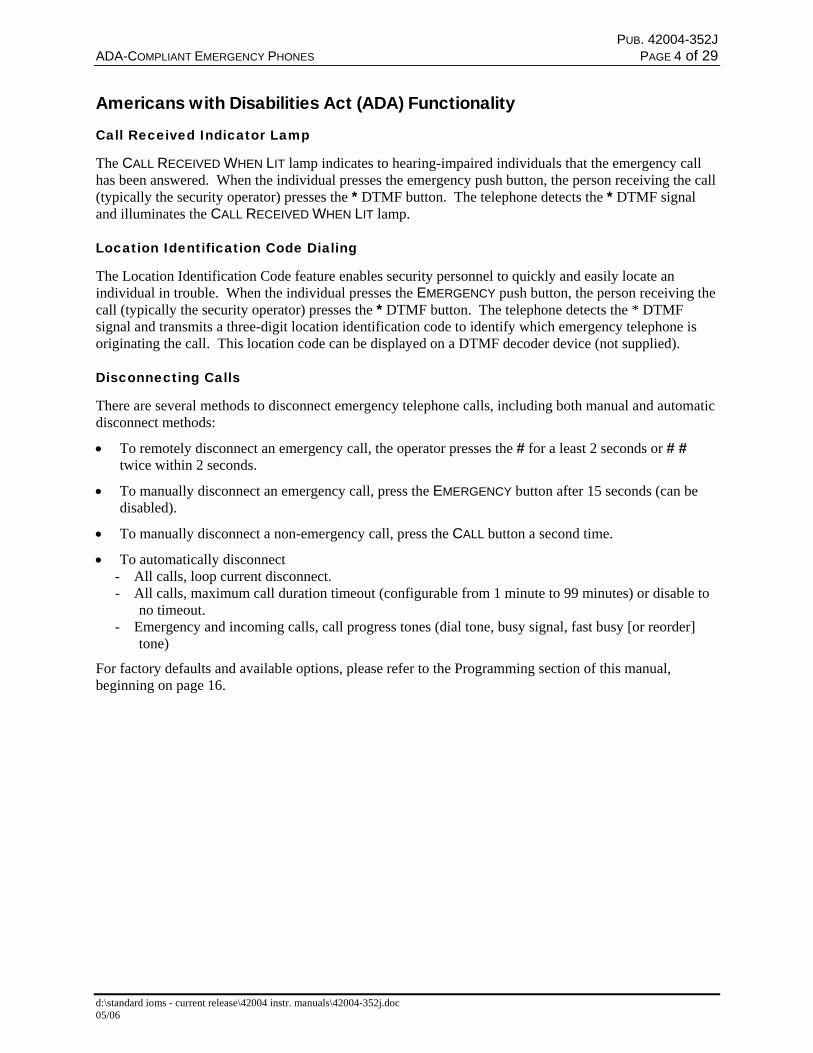
Americans with Disabilities Act (ADA) Functionality
Call Received Indicator Lamp
The CALL RECEIVED WHEN LIT lamp indicates to hearing-impaired individuals that the emergency callhas been answered. When the individual presses the emergency push button, the person receiving the call(typically the security operator) presses the * DTMF button. The telephone detects the * DTMF signaland illuminates the CALL RECEIVED WHEN LIT lamp.
Location Identification Code Dialing
The Location Identification Code feature enables security personnel to quickly and easily locate anindividual in trouble. When the individual presses the EMERGENCY push button, the person receiving thecall (typically the security operator) presses the * DTMF button. The telephone detects the * DTMFsignal and transmits a three-digit location identification code to identify which emergency telephone isoriginating the call. This location code can be displayed on a DTMF decoder device (not supplied).
Disconnecting Calls
There are several methods to disconnect emergency telephone calls, including both manual and automaticdisconnect methods:
• To remotely disconnect an emergency call, the operator presses the # for a least 2 seconds or # #twice within 2 seconds.
• To manually disconnect an emergency call, press the EMERGENCY button after 15 seconds (can bedisabled).
• To manually disconnect a non-emergency call, press the CALL button a second time.
• To automatically disconnect- All calls, loop current disconnect.- All calls, maximum call duration timeout (configurable from 1 minute to 99 minutes) or disable to
no timeout.- Emergency and incoming calls, call progress tones (dial tone, busy signal, fast busy [or reorder]
tone)
For factory defaults and available options, please refer to the Programming section of this manual,beginning on page 16.
PUB. 42004-352JADA-COMPLIANT EMERGENCY PHONES PAGE 5 of 29
d:\standard ioms - current release\42004 instr. manuals\42004-352j.doc05/06
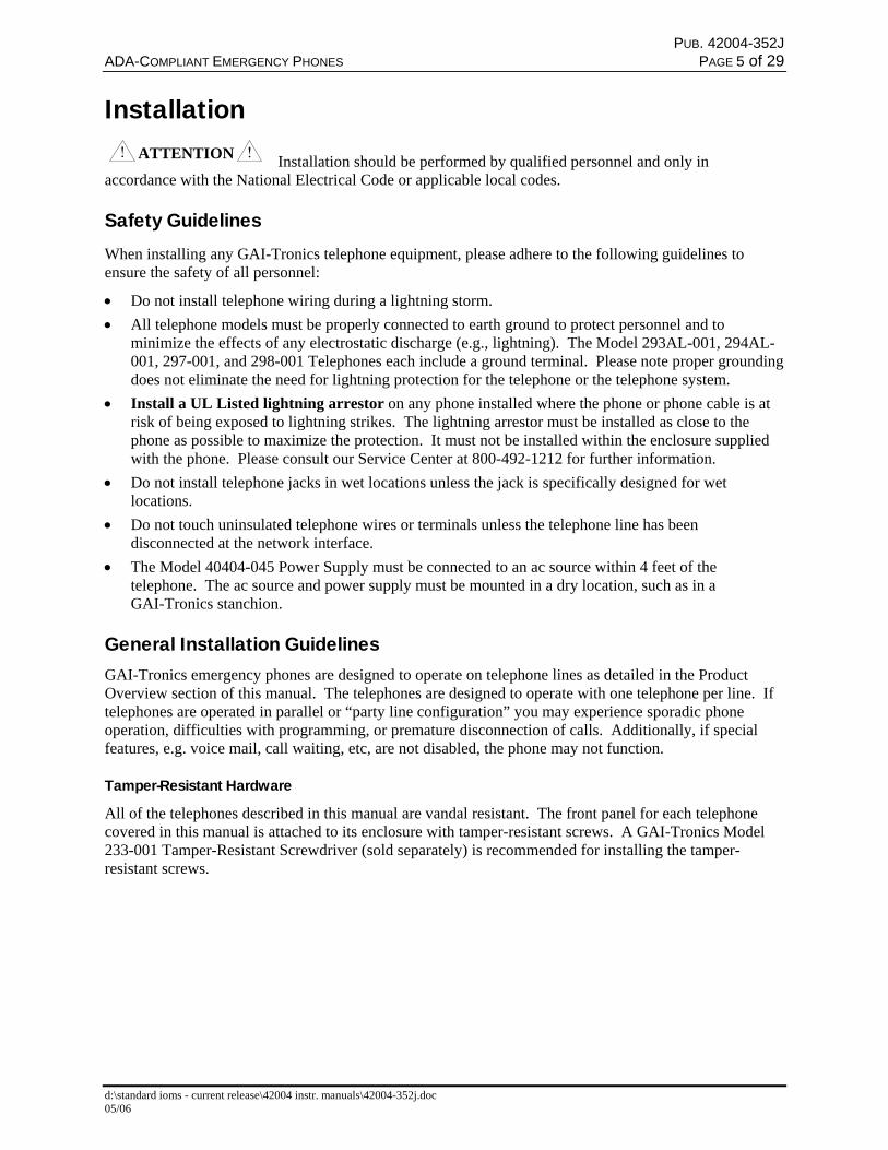
InstallationATTENTION Installation should be performed by qualified personnel and only in
accordance with the National Electrical Code or applicable local codes.
Safety GuidelinesWhen installing any GAI-Tronics telephone equipment, please adhere to the following guidelines toensure the safety of all personnel:
• Do not install telephone wiring during a lightning storm.• All telephone models must be properly connected to earth ground to protect personnel and to
minimize the effects of any electrostatic discharge (e.g., lightning). The Model 293AL-001, 294AL-001, 297-001, and 298-001 Telephones each include a ground terminal. Please note proper groundingdoes not eliminate the need for lightning protection for the telephone or the telephone system.
• Install a UL Listed lightning arrestor on any phone installed where the phone or phone cable is atrisk of being exposed to lightning strikes. The lightning arrestor must be installed as close to thephone as possible to maximize the protection. It must not be installed within the enclosure suppliedwith the phone. Please consult our Service Center at 800-492-1212 for further information.
• Do not install telephone jacks in wet locations unless the jack is specifically designed for wetlocations.
• Do not touch uninsulated telephone wires or terminals unless the telephone line has beendisconnected at the network interface.
• The Model 40404-045 Power Supply must be connected to an ac source within 4 feet of thetelephone. The ac source and power supply must be mounted in a dry location, such as in aGAI-Tronics stanchion.
General Installation GuidelinesGAI-Tronics emergency phones are designed to operate on telephone lines as detailed in the ProductOverview section of this manual. The telephones are designed to operate with one telephone per line. Iftelephones are operated in parallel or “party line configuration” you may experience sporadic phoneoperation, difficulties with programming, or premature disconnection of calls. Additionally, if specialfeatures, e.g. voice mail, call waiting, etc, are not disabled, the phone may not function.
Tamper-Resistant Hardware
All of the telephones described in this manual are vandal resistant. The front panel for each telephonecovered in this manual is attached to its enclosure with tamper-resistant screws. A GAI-Tronics Model233-001 Tamper-Resistant Screwdriver (sold separately) is recommended for installing the tamper-resistant screws.

PUB. 42004-352JADA-COMPLIANT EMERGENCY PHONES PAGE 6 of 29
d:\standard ioms - current release\42004 instr. manuals\42004-352j.doc05/06
Conduit Installation Details
GAI-Tronics recommends installing telephone lines in conduit to protect against accidental damage andvandalism. To prevent moisture from entering the enclosure, we strongly recommend the following:
• Conduit should enter the enclosure from the bottom.• Sealed fittings should be installed at all cable entry points.• Silicone sealant or equivalent should be applied around and inside all conduit entries.
Please refer to the examples below for the recommended conduit installation details.
Figure 1. Bottom entry conduit recommended fornon-metallic enclosures
Figure 2. Top entry conduit installation for non-metallic enclosures (NOT recommended)
Figure 3. Bottom entry conduit installation detailsfor metallic enclosures
Figure 4. Top entry conduit installation details formetallic enclosures (NOT recommended)
PUB. 42004-352JADA-COMPLIANT EMERGENCY PHONES PAGE 7 of 29
d:\standard ioms - current release\42004 instr. manuals\42004-352j.doc05/06
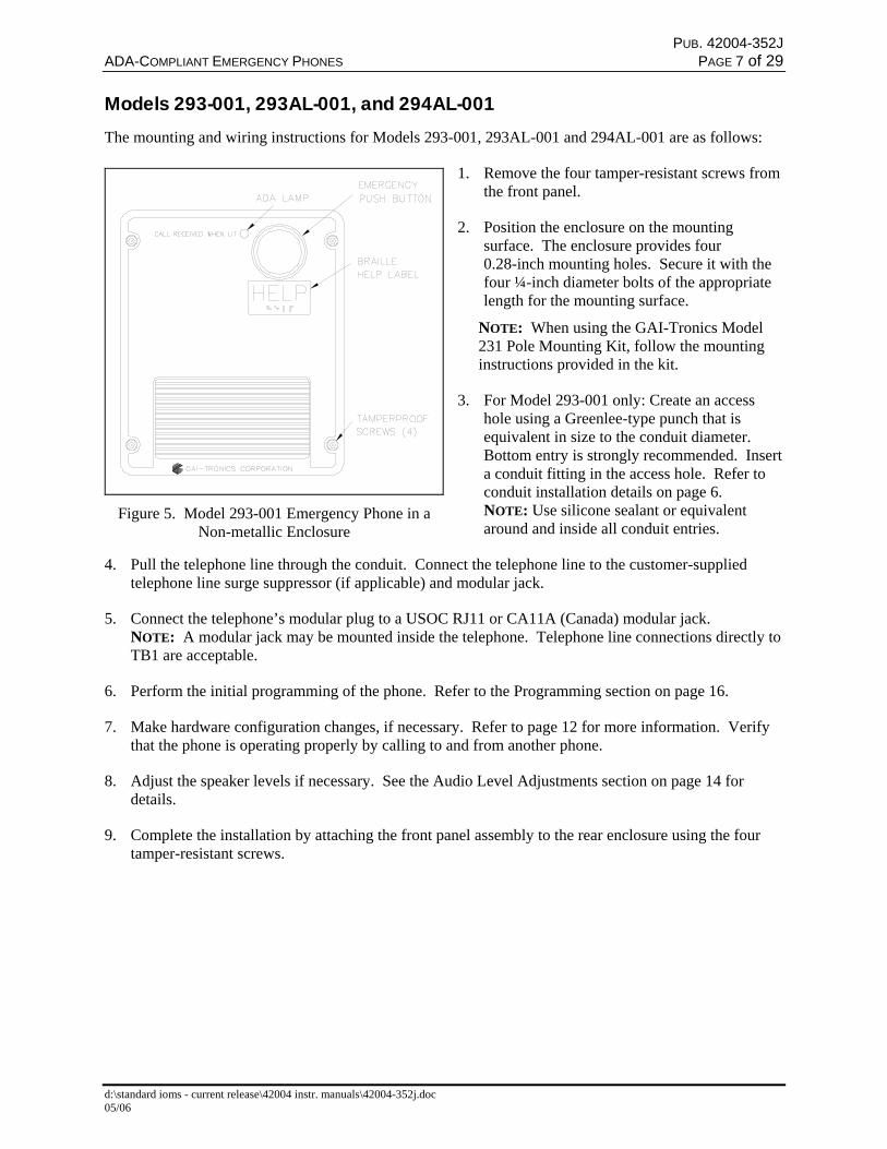
Models 293-001, 293AL-001, and 294AL-001The mounting and wiring instructions for Models 293-001, 293AL-001 and 294AL-001 are as follows:
1. Remove the four tamper-resistant screws fromthe front panel.
2. Position the enclosure on the mountingsurface. The enclosure provides four0.28-inch mounting holes. Secure it with thefour ¼-inch diameter bolts of the appropriatelength for the mounting surface.
NOTE: When using the GAI-Tronics Model231 Pole Mounting Kit, follow the mountinginstructions provided in the kit.
3. For Model 293-001 only: Create an accesshole using a Greenlee-type punch that isequivalent in size to the conduit diameter.Bottom entry is strongly recommended. Inserta conduit fitting in the access hole. Refer toconduit installation details on page 6.NOTE: Use silicone sealant or equivalentaround and inside all conduit entries.
4. Pull the telephone line through the conduit. Connect the telephone line to the customer-suppliedtelephone line surge suppressor (if applicable) and modular jack.
5. Connect the telephone’s modular plug to a USOC RJ11 or CA11A (Canada) modular jack.NOTE: A modular jack may be mounted inside the telephone. Telephone line connections directly toTB1 are acceptable.
6. Perform the initial programming of the phone. Refer to the Programming section on page 16.
7. Make hardware configuration changes, if necessary. Refer to page 12 for more information. Verifythat the phone is operating properly by calling to and from another phone.
8. Adjust the speaker levels if necessary. See the Audio Level Adjustments section on page 14 fordetails.
9. Complete the installation by attaching the front panel assembly to the rear enclosure using the fourtamper-resistant screws.
Figure 5. Model 293-001 Emergency Phone in aNon-metallic Enclosure
PUB. 42004-352JADA-COMPLIANT EMERGENCY PHONES PAGE 8 of 29
d:\standard ioms - current release\42004 instr. manuals\42004-352j.doc05/06
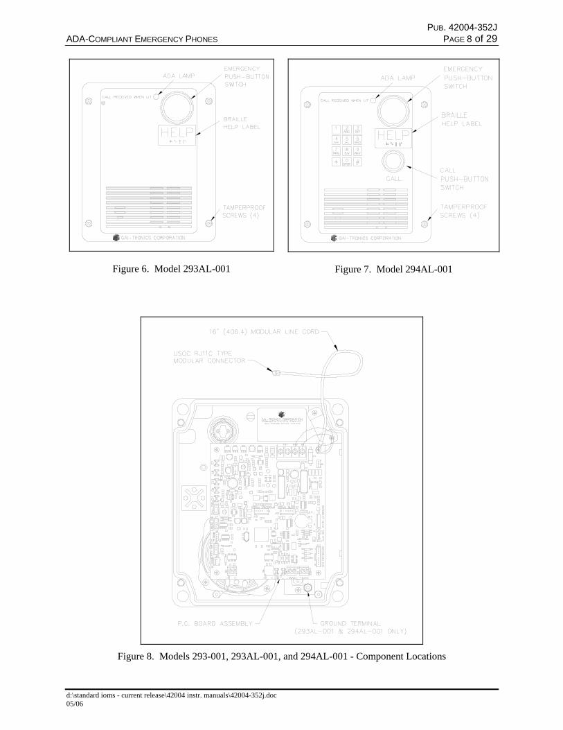
Figure 6. Model 293AL-001 Figure 7. Model 294AL-001
Figure 8. Models 293-001, 293AL-001, and 294AL-001 - Component Locations

PUB. 42004-352JADA-COMPLIANT EMERGENCY PHONES PAGE 9 of 29
d:\standard ioms - current release\42004 instr. manuals\42004-352j.doc05/06
Models 297-001 and 298-001
Figure 9. Model 297-001 Figure 10. Model 298-001
Stanchion or Flush-mount Applications
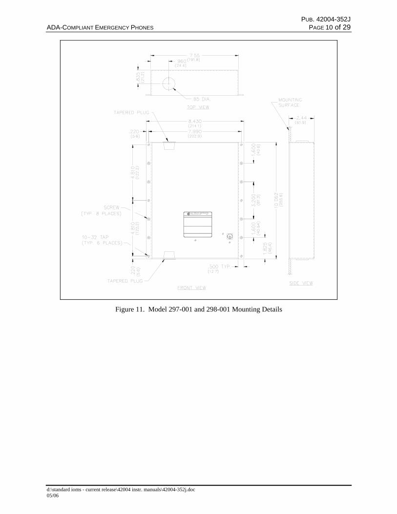
1. When mounting in a GAI-Tronics Model 234 Series Stanchion, or for flush-mount installations, thesupplied back box must be used to mount the Model 297-001 or 298-001 Telephone. Mount the backbox to the structure using the appropriate hardware. Refer to Figure 11 cutout dimensions.
2. If mounted outdoors, the installation of a telephone line suppressor (customer-supplied) on thetelephone line is recommended.
3. Remove the tapered plug from the top or bottom cable entry hole in the back box, and install thetelephone line and cable fitting.
4. Telephone line connections directly to TB1 are acceptable.
5. If using the modular jack, remove the cover, and connect the red and green wires of the telephone lineto the red and green wires of the modular jack. Replace the modular jack cover.
6. Connect the telephone’s modular plug to a USOC RJ11 or CA11A (Canada) modular connector or (ifapplicable) the telephone line suppressor. Refer to Figure 8 for the Model 297-001 and 298-001component locations.
7. Perform the initial programming of the phone. Refer to the Programming section beginning on page16.
8. Make hardware configuration changes, if necessary. Refer to page 12. Verify operation by calling toand from another phone.
9. Adjust the speaker levels if necessary. Refer to the Audio Level Adjustments section on page 14.
10. Attach the telephone’s front panel to the mounting flanges of the back box using the six supplied#10-32 tamper-resistant screws and washers.
PUB. 42004-352JADA-COMPLIANT EMERGENCY PHONES PAGE 10 of 29
d:\standard ioms - current release\42004 instr. manuals\42004-352j.doc05/06
Figure 11. Model 297-001 and 298-001 Mounting Details

PUB. 42004-352JADA-COMPLIANT EMERGENCY PHONES PAGE 11 of 29
d:\standard ioms - current release\42004 instr. manuals\42004-352j.doc05/06
Figure 12. Model 297-001 and 298-001 - Component Locations(shown with connection to optional GAI-Tronics 530FB/531A Beacon)
Connecting a Beacon
Figure 12 above shows a typical connection detail of the GAI-Tronics 530FB/531A Beacon (soldseparately).
PUB. 42004-352JADA-COMPLIANT EMERGENCY PHONES PAGE 12 of 29
d:\standard ioms - current release\42004 instr. manuals\42004-352j.doc05/06
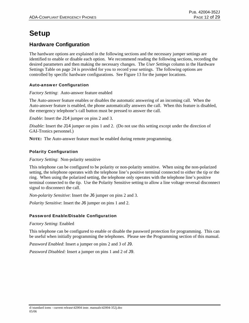
SetupHardware ConfigurationThe hardware options are explained in the following sections and the necessary jumper settings areidentified to enable or disable each option. We recommend reading the following sections, recording thedesired parameters and then making the necessary changes. The User Settings column in the HardwareSettings Table on page 24 is provided for you to record your settings. The following options arecontrolled by specific hardware configurations. See Figure 13 for the jumper locations.
Auto-answer Configuration
Factory Setting: Auto-answer feature enabled
The Auto-answer feature enables or disables the automatic answering of an incoming call. When theAuto-answer feature is enabled, the phone automatically answers the call. When this feature is disabled,the emergency telephone’s call button must be pressed to answer the call.
Enable: Insert the J14 jumper on pins 2 and 3.
Disable: Insert the J14 jumper on pins 1 and 2. (Do not use this setting except under the direction ofGAI-Tronics personnel.)
NOTE: The Auto-answer feature must be enabled during remote programming.
Polarity Configuration
Factory Setting: Non-polarity sensitive
This telephone can be configured to be polarity or non-polarity sensitive. When using the non-polarizedsetting, the telephone operates with the telephone line’s positive terminal connected to either the tip or thering. When using the polarized setting, the telephone only operates with the telephone line’s positiveterminal connected to the tip. Use the Polarity Sensitive setting to allow a line voltage reversal disconnectsignal to disconnect the call.
Non-polarity Sensitive: Insert the J6 jumper on pins 2 and 3.
Polarity Sensitive: Insert the J6 jumper on pins 1 and 2.
Password Enable/Disable Configuration
Factory Setting: Enabled
This telephone can be configured to enable or disable the password protection for programming. This canbe useful when initially programming the telephones. Please see the Programming section of this manual.
Password Enabled: Insert a jumper on pins 2 and 3 of J9.
Password Disabled: Insert a jumper on pins 1 and 2 of J9.
PUB. 42004-352JADA-COMPLIANT EMERGENCY PHONES PAGE 13 of 29
d:\standard ioms - current release\42004 instr. manuals\42004-352j.doc05/06
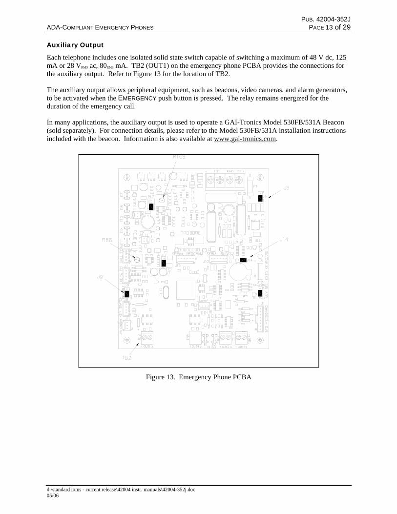
Auxiliary Output
Each telephone includes one isolated solid state switch capable of switching a maximum of 48 V dc, 125mA or 28 VRMS ac, 80RMS mA. TB2 (OUT1) on the emergency phone PCBA provides the connections forthe auxiliary output. Refer to Figure 13 for the location of TB2.
The auxiliary output allows peripheral equipment, such as beacons, video cameras, and alarm generators,to be activated when the EMERGENCY push button is pressed. The relay remains energized for theduration of the emergency call.
In many applications, the auxiliary output is used to operate a GAI-Tronics Model 530FB/531A Beacon(sold separately). For connection details, please refer to the Model 530FB/531A installation instructionsincluded with the beacon. Information is also available at www.gai-tronics.com.
Figure 13. Emergency Phone PCBA
PUB. 42004-352JADA-COMPLIANT EMERGENCY PHONES PAGE 14 of 29
d:\standard ioms - current release\42004 instr. manuals\42004-352j.doc05/06
Audio Level Adjustments
Speaker Volume Adjustments
The speaker volume and microphone sensitivity are factory set to nominal levels that are acceptable formost installations. However, some installations may require adjustments for the speaker and microphone.Both the speaker and microphone adjustments are made using potentiometers on the emergency phonePCBA. R106 is the speaker volume adjustment, and R88 is the microphone sensitivity adjustment.Please refer to Figure 13 for the potentiometer locations.
After making any adjustments to the audio levels, perform the automatic line level compensation asdetailed below.
When the phones leave the factory, the microphone potentiometer is set near minimum, and the speakerpot is set to maximum. The speaker volume potentiometer (R106) provides a 6-dB range of adjustmentand the microphone sensitivity potentiometer (R88) provides a 12-dB range of adjustment.
Special care must be given to adjusting the speaker volume and microphone level. If one or both of thelevels are set too high, acoustic feedback (howling) can occur. If acoustic feedback occurs, werecommend returning both potentiometers to the nominal factory settings and beginning the adjustmentagain from this point.
Additionally, the acoustical characteristics of the emergency phone with the front panel removed aredifferent than when the front panel is tightly mounted in the enclosure. After making any volumeadjustments, we recommend mounting the front panel to the enclosure and testing the phone again.
Automatic Line Level Compensation for Optimum Audio Performance
Every telephone line has different audio and electrical characteristics. To accommodate the varying lines,the telephone has an automatic line level compensation function. When a telephone is first installed andconnected to a telephone line, we recommend resetting the automatic level compensation feature. Theautomatic line level compensation feature is reset remotely (See the Remote Programming Section of thismanual) or locally with the #2316 command, as follows:
For single button emergency phones:
1. Remove the phone from the back box or enclosure.
2. Disconnect the EMERGENCY push button from J7, the “Emerg PB” socket on the phone PCBA.
3. Connect the EMERGENCY push button to J1, the “Call PB” socket on the phone PCBA.
4. On the PCBA, enable auto-answer by placing a jumper between pins 2 and 3 on J14 and disablepassword protection by removing the jumper from J9.
5. Connect a keypad to J13. (Keypad, Part No. 51035-011, and Keypad Cable Assembly, Part No.61504-048 are sold separately).
6. Press the EMERGENCY button. After you hear the dial tone, simultaneously press the 1 and # keys.After a confirmation tone is heard, enter the command #2316. To hang up the phone, press theEMERGENCY button or wait for the phone to time out.
7. Press the EMERGENCY push button.When dial tone is steady (with no volume variations), the process is complete. Depending on thephone line and the duration dial tone, it may be necessary to repeat this step one or more times.
PUB. 42004-352JADA-COMPLIANT EMERGENCY PHONES PAGE 15 of 29
d:\standard ioms - current release\42004 instr. manuals\42004-352j.doc05/06
8. Disconnect the EMERGENCY push button from J1, the “Call PB” socket on the phone PCBA.
9. Reconnect the EMERGENCY push button to J7, the “Emerg PB” socket on the phone PCBA.
10. Configure the phone for auto-answer and password protection as required. Please see theProgramming section of this manual beginning on page 16.
11. Disconnect the keypad from J13.
12. Install the phone in the back box or enclosure.
For emergency phones with a CALL push button and keypad:
Disable password protection by removing the jumper from J9.
1. Press the CALL button. After you hear the dial tone, simultaneously press the 1 and # keys. Afteryou hear the confirmation tone, enter the command #2316. To hang up the phone, press the CALLbutton or wait for the phone to time out.
2. Press the CALL push button.When the dial tone is steady (with no volume variations), the process is complete. Depending on thephone line and the duration of dial tone, it may be necessary to repeat this step one or more times.

PUB. 42004-352JADA-COMPLIANT EMERGENCY PHONES PAGE 16 of 29
d:\standard ioms - current release\42004 instr. manuals\42004-352j.doc05/06
ProgrammingThe telephone can be programmed remotely from another telephone, or locally at the emergencytelephone. To program the Model 294AL-001 and Model 298-001 locally, the front panel keypad can beused. However, to program the Models 293-001, 293AL-001, and 297-001 locally, a Model 51035-011Keypad must be connected to J13 on the telephone PCBA using the Model 51504-048 Keypad CableAssembly. Refer to Figure 8 for locations. Refer to the Local Programming section on page 17.
For remote programming, a touch-tone (DTMF) telephone connected to a separate central office (CO) orprivate branch exchange (PBX) line is required. See the Remote Programming section below.
Remote ProgrammingThe programming mode is accessed by dialing a four-digit programming password. Should it becomenecessary to bypass the password protection feature, see the Password Disabled Programming section onpage 17.
Password Enabled Programming
1. Enable the password protection feature—insert the J9 jumper on pins 2 and 3.
2. Enable the auto-answer feature—insert the J14 jumper on pins 2 and 3.
3. Using a touch-tone telephone, call the emergency telephone. The emergency telephone automaticallyanswers the call and generates a splash tone followed by a success tone (single beep).
4. Dial the four-digit password. If the password has not been altered, dial 2468 (factory setting).Otherwise, dial the preprogrammed user password. A success tone (single beep) is generated toindicate the programming mode has been accessed.
NOTES:• The telephone automatically times out if 20 seconds elapse between digit entries, or if an invalid
password is entered.
• If DTMF digits have not been dialed within three seconds of the call initiation, the telephoneremains off-hook and the programming mode is terminated.
• If the success tone is not generated, the telephone has failed to recognize the password.Therefore, the telephone must then be programmed with the password disabled. See thePassword Disabled Programming section on page 17.
5. After you hear the success tone, begin entering the desired user-programmable parameters. Refer tothe Programming Sequences section on page 19. A success tone (single beep) is generated each timea new parameter is accepted. An error tone (two beeps) is generated to indicate an error. If an errortone is generated, verify the programming sequence, and enter the sequence again.
6. Terminate the programming by placing the touch-tone telephone on-hook.
PUB. 42004-352JADA-COMPLIANT EMERGENCY PHONES PAGE 17 of 29
d:\standard ioms - current release\42004 instr. manuals\42004-352j.doc05/06
Password Disabled Programming
1. Disable the password protection feature—insert the J9 jumper on pins 1 and 2.
2. Enable the auto-answer feature—insert the J14 jumper on pins 2 and 3.
3. Using the touch-tone telephone, call the emergency telephone. The emergency telephoneautomatically answers the call and generates a splash tone followed by a success tone (single beep).
4. Begin entering the desired programmable parameters. See the Programming Sequences section onpage 19. A success tone (single beep) is generated each time a new parameter is accepted. An errortone (two beeps) is generated to indicate an error. If an error tone is generated, verify theprogramming sequence, and enter the sequence again.
NOTE: The telephone automatically times out if 20 seconds elapse between digit entries.
5. Terminate the programming by placing the touch-tone telephone on-hook.
Local ProgrammingFor Models 293-001, 293AL-001, and 297-001, the procedure is as follows:
1. Connect keypad to connector J13. See Figure 8 and Figure 12 for details. Contact GAI-TronicsField Service Department for details.
2. Temporarily move the EMERGENCY push-button switch harness from connector J7 to the CALLpush-button connector J1.
3. Disable the password protection feature—insert the J9 jumper on pins 2 and 1.
4. Press the EMERGENCY push button. A dial tone is broadcast over the speaker. Simultaneouslypress 1 and # on the keypad. The telephone generates a splash tone followed by a success tone.
5. Enter the desired programmable parameters. See the Programming Sequences section below.
A success tone (single tone [DTMF #]) tone is generated each time a new parameter is accepted. Anerror tone (double beep) is generated to indicate an error. If an error tone is generated, verify theprogramming sequence is correct, and enter the sequence again.
NOTES:• The telephone is off-hook during local programming. Therefore, programming should be
completed quickly to avoid any off-hook timeouts controlled by the CO or PBX.• The telephone will automatically time out if 20 seconds elapse between digit entries.
6. Terminate the programming by pressing the EMERGENCY push button.
7. Disconnect the keypad from connector J13.
8. Return the EMERGENCY push-button switch to connector J7.
9. Enable the password protection feature—insert the J9 jumper on pins 3 and 2.

PUB. 42004-352JADA-COMPLIANT EMERGENCY PHONES PAGE 18 of 29
d:\standard ioms - current release\42004 instr. manuals\42004-352j.doc05/06
For Models 294AL-001, and 298-001, the procedure is as follows:
1. Disable the password protection feature—insert the J9 jumper on pins 2 and 1.
2. Press the CALL push button. A dial tone is broadcast over the speaker. Simultaneously press 1 and #on the phone keypad. The telephone generates a splash tone followed by a success tone.
3. Enter the desired programmable parameters. See the Programming Sequences section below.
A success tone (single tone [DTMF #]) tone is generated each time a new parameter is accepted. Anerror tone (double beep) is generated to indicate an error. If an error tone is generated, verify theprogramming sequence is correct, and enter the sequence again.
NOTES:• The telephone is off-hook during local programming. Therefore, programming should be
completed quickly to avoid any off-hook timeouts controlled by the CO or PBX.• The telephone will automatically time out if 20 seconds elapse between digit entries.
4. Terminate the programming by pressing the CALL push button.
5. Enable the password protection feature—insert the J9 jumper on pins 3 and 2.

PUB. 42004-352JADA-COMPLIANT EMERGENCY PHONES PAGE 19 of 29
d:\standard ioms - current release\42004 instr. manuals\42004-352j.doc05/06
Programming SequencesThe programming information on the following pages explains theprogramming options. The telephone is shipped from the factorywith a set of default parameters that are listed in the ProgrammingTable on page 24. A User Settings section has been provided inthe Programming Table for the user to record the selectedprogramming parameters.
It is recommended that the user read the sections that follow, record the desired parameters in the UserSettings section of the Programming Table, and then complete the programming using the instructionsfrom either the Remote Programming or the Local Programming section.
Dialing Options
The emergency telephones can be configured for either auto-dialing or ring-down operation. Select thedialing option that fits your application. The dialing options are explained in detail in the followingsections.
Auto-dialing
The EMERGENCY push button can be programmed to call three unique telephone numbers. The uniquetelephone numbers include a primary telephone number and two backup, or roll over, numbers. In theevent an emergency call cannot connect to the primary telephone number (i.e., a busy signal or noanswer), the emergency phone will automatically dial the first backup, or roll over, number. Again, in theevent an emergency call cannot connect to first back-up telephone number, the emergency phone willautomatically dial the second backup, or roll over, number. This sequence will continue until theemergency call is answered, or the sequence is repeated three times for a total of 12 call attempts.
For the rollover feature to function properly, all three auto-dial memories must be programmed with validtelephone numbers. The three auto-dial numbers can be the same or any combination of phone numbers.If the phone is programmed with only one or two auto-dial numbers, the rollover operation will notfunction and the numbers will only be dialed one time.
If an emergency phone is connected to a PBX, PABX, KSU, etc., telephone system, the emergency phonecan be programmed to access outside CO lines. Typically access to a CO line requires adding a digit (e.g.9) to the auto-dial number. Also, a “pause” may be required in the auto-dial number. The pause typicallyis required to wait for secondary (CO line) dial tone. See the example in the Emergency Button Auto-dialNumber 1 in the table below.
In addition to the pause, the emergency telephone has a programmable Primary Dial Tone Delay andSecondary Dial Tone Delay. Both delays determine the amount of time the emergency phone will waitbefore dialing the stored telephone number. The Secondary Dial Tone Delay can only be used if a “9” isdialed to gain access to a CO line.
Programming Key
D = digit 0-9, *, or # N = digit 0-9 L = 0 - Disable, 1 - Enable T = 0-350 ms, 1-50 ms, 2-25 ms

PUB. 42004-352JADA-COMPLIANT EMERGENCY PHONES PAGE 20 of 29
d:\standard ioms - current release\42004 instr. manuals\42004-352j.doc05/06
Ring-down Operation
Ring-down operation enables the telephone to go off-hook when the EMERGENCY push button is pressed.The ring-down system must detect loop current and ring-down to the appropriate telephone.
FeatureKeySequence Description Default
EmergencyButton Auto-dialNumber 1
DD ... *1 Assigns a telephone number to the auto-dial memory 1. DD ...represents the telephone number, which can be up to 20 digits inlength.
For access to an outside line, a pause may be required in thetelephone number to wait for secondary dial tone. The #represents a pause in the telephone number.
Examples:
To assign the police emergency number 911 to the auto-dialbutton, enter 911*1.
To assign 911 when a “9” is required to gain access to a COline, enter 9*#911*1.
To store * or # as part of the auto-dial number, (such as forspeed dialing), enter these digits twice in succession.
*123456789*0#
EmergencyButton Auto-dialNumber 2
DD ... *2 Same as Emergency Button Auto-dial Number 1 except thesequence ends in *2 instead of *1.
None
EmergencyButton Auto-dialNumber 3
DD ... *3 Same as Emergency Button Auto-dial Number 1 except thesequence ends in *3 instead of *1.
None
Call ButtonAuto-dial
DD ... *4 Same as Emergency Button Auto-dial Number 1 except thesequence ends in *4 instead of *1.
None
Primary DialTone Delay
# 1 0 N N The dial tone delay is the amount of time the unit waits for adial tone before auto-dialing the telephone number. (00[infinite]; 01-15 seconds)
Example: To wait five seconds for a dial tone, enter # 1 0 0 5.
00(Infinite)
Secondary DialTone Delay
# 1 1 N N This feature is only used if you must dial 9 to access an outsideline. It determines the amount of time (00-15 seconds) thetelephone waits for a second dial tone. The first programmingstep indicated you must program 9*# and the number you wantthe auto-dial to access. This programming parameter allowsyou to choose the amount of time the telephone waits afterencountering # before dialing the auto-dial number.Example: To wait ten seconds for the second dial tone, enter# 1 1 1 0.
00 (0seconds)
Ring-downOperation
*1 This option clears the telephone number to prevent auto-dialingwhen the button is pressed. Once the button is pressed, the ring-down system must detect loop current and ring-down to theappropriate telephone.
None
PUB. 42004-352JADA-COMPLIANT EMERGENCY PHONES PAGE 21 of 29
d:\standard ioms - current release\42004 instr. manuals\42004-352j.doc05/06
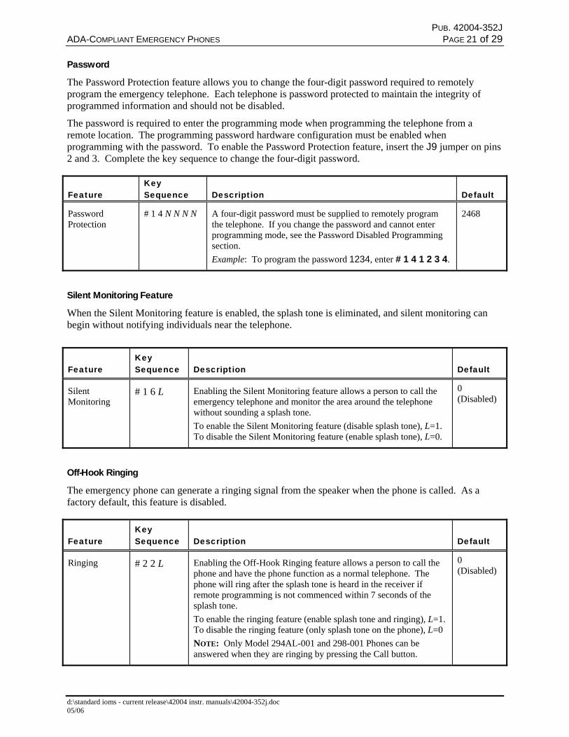
Password
The Password Protection feature allows you to change the four-digit password required to remotelyprogram the emergency telephone. Each telephone is password protected to maintain the integrity ofprogrammed information and should not be disabled.
The password is required to enter the programming mode when programming the telephone from aremote location. The programming password hardware configuration must be enabled whenprogramming with the password. To enable the Password Protection feature, insert the J9 jumper on pins2 and 3. Complete the key sequence to change the four-digit password.
FeatureKeySequence Description Default
PasswordProtection
# 1 4 N N N N A four-digit password must be supplied to remotely programthe telephone. If you change the password and cannot enterprogramming mode, see the Password Disabled Programmingsection.Example: To program the password 1234, enter # 1 4 1 2 3 4.
2468
Silent Monitoring Feature
When the Silent Monitoring feature is enabled, the splash tone is eliminated, and silent monitoring canbegin without notifying individuals near the telephone.
FeatureKeySequence Description Default
SilentMonitoring
# 1 6 L Enabling the Silent Monitoring feature allows a person to call theemergency telephone and monitor the area around the telephonewithout sounding a splash tone.To enable the Silent Monitoring feature (disable splash tone), L=1.To disable the Silent Monitoring feature (enable splash tone), L=0.
0(Disabled)
Off-Hook Ringing
The emergency phone can generate a ringing signal from the speaker when the phone is called. As afactory default, this feature is disabled.
FeatureKeySequence Description Default
Ringing # 2 2 L Enabling the Off-Hook Ringing feature allows a person to call thephone and have the phone function as a normal telephone. Thephone will ring after the splash tone is heard in the receiver ifremote programming is not commenced within 7 seconds of thesplash tone.To enable the ringing feature (enable splash tone and ringing), L=1.To disable the ringing feature (only splash tone on the phone), L=0NOTE: Only Model 294AL-001 and 298-001 Phones can beanswered when they are ringing by pressing the Call button.
0(Disabled)
PUB. 42004-352JADA-COMPLIANT EMERGENCY PHONES PAGE 22 of 29
d:\standard ioms - current release\42004 instr. manuals\42004-352j.doc05/06
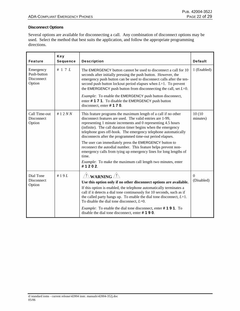
Disconnect Options
Several options are available for disconnecting a call. Any combination of disconnect options may beused. Select the method that best suits the application, and follow the appropriate programmingdirections.
FeatureKeySequence Description Default
EmergencyPush-buttonDisconnectOption
# 1 7 L The EMERGENCY button cannot be used to disconnect a call for 10seconds after initially pressing the push button. However, theemergency push button can be used to disconnect calls after the ten-second push button lockout period elapses when L=1. To preventthe EMERGENCY push button from disconnecting the call, set L=0.
Example: To enable the EMERGENCY push button disconnect,enter # 1 7 1. To disable the EMERGENCY push buttondisconnect, enter # 1 7 0.
1 (Enabled)
Call Time-outDisconnectOption
# 1 2 N N This feature programs the maximum length of a call if no otherdisconnect features are used. The valid entries are 1-99,representing 1 minute increments and 0 representing 4.5 hours(infinite). The call duration timer begins when the emergencytelephone goes off-hook. The emergency telephone automaticallydisconnects after the programmed time-out period elapses.The user can immediately press the EMERGENCY button toreconnect the autodial number. This feature helps prevent non-emergency calls from tying up emergency lines for long lengths oftime.Example: To make the maximum call length two minutes, enter# 1 2 0 2.
10 (10 minutes)
Dial ToneDisconnectOption
# 1 9 L WARNINGUse this option only if no other disconnect options are available.If this option is enabled, the telephone automatically terminates acall if it detects a dial tone continuously for 10 seconds, such as ifthe called party hangs up. To enable the dial tone disconnect, L=1.To disable the dial tone disconnect, L=0.
Example: To enable the dial tone disconnect, enter # 1 9 1. Todisable the dial tone disconnect, enter # 1 9 0.
0(Disabled)
PUB. 42004-352JADA-COMPLIANT EMERGENCY PHONES PAGE 23 of 29
d:\standard ioms - current release\42004 instr. manuals\42004-352j.doc05/06
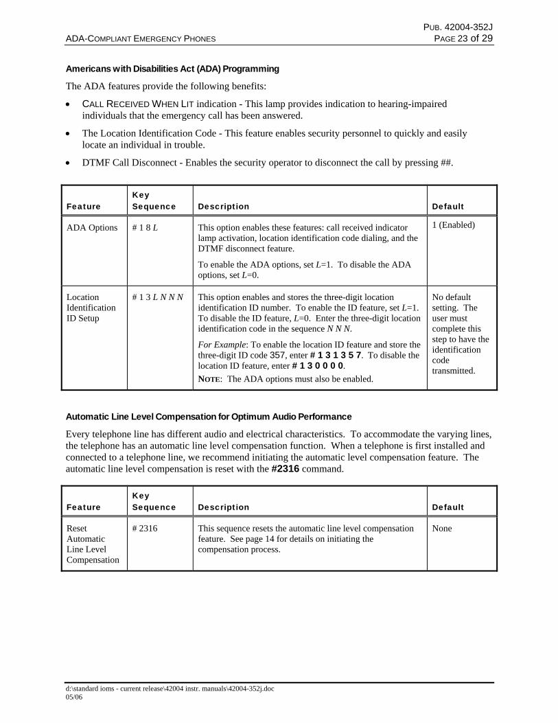
Americans with Disabilities Act (ADA) Programming
The ADA features provide the following benefits:
• CALL RECEIVED WHEN LIT indication - This lamp provides indication to hearing-impairedindividuals that the emergency call has been answered.
• The Location Identification Code - This feature enables security personnel to quickly and easilylocate an individual in trouble.
• DTMF Call Disconnect - Enables the security operator to disconnect the call by pressing ##.
FeatureKeySequence Description Default
ADA Options # 1 8 L This option enables these features: call received indicatorlamp activation, location identification code dialing, and theDTMF disconnect feature.
To enable the ADA options, set L=1. To disable the ADAoptions, set L=0.
1 (Enabled)
LocationIdentificationID Setup
# 1 3 L N N N This option enables and stores the three-digit locationidentification ID number. To enable the ID feature, set L=1.To disable the ID feature, L=0. Enter the three-digit locationidentification code in the sequence N N N.
For Example: To enable the location ID feature and store thethree-digit ID code 357, enter # 1 3 1 3 5 7. To disable thelocation ID feature, enter # 1 3 0 0 0 0.NOTE: The ADA options must also be enabled.
No defaultsetting. Theuser mustcomplete thisstep to have theidentificationcodetransmitted.
Automatic Line Level Compensation for Optimum Audio Performance
Every telephone line has different audio and electrical characteristics. To accommodate the varying lines,the telephone has an automatic line level compensation function. When a telephone is first installed andconnected to a telephone line, we recommend initiating the automatic level compensation feature. Theautomatic line level compensation is reset with the #2316 command.
FeatureKeySequence Description Default
ResetAutomaticLine LevelCompensation
# 2316 This sequence resets the automatic line level compensationfeature. See page 14 for details on initiating thecompensation process.
None
PUB. 42004-352JADA-COMPLIANT EMERGENCY PHONES PAGE 24 of 29
d:\standard ioms - current release\42004 instr. manuals\42004-352j.doc05/06
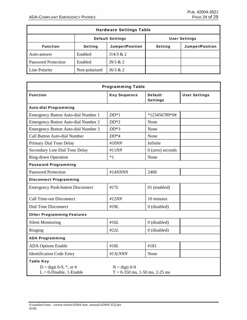
Hardware Settings Table
Default Settings User Settings
Function Setting Jumper/Position Setting Jumper/Position
Auto-answer Enabled J14/3 & 2
Password Protection Enabled J9/3 & 2
Line Polarity Non-polarized J6/3 & 2
Programming Table
Function Key Sequence DefaultSettings
User Settings
Auto-dial Programming
Emergency Button Auto-dial Number 1 DD*1 *123456789*0#Emergency Button Auto-dial Number 2 DD*2 NoneEmergency Button Auto-dial Number 3 DD*3 NoneCall Button Auto-dial Number DD*4 NonePrimary Dial Tone Delay #10NN InfiniteSecondary Line Dial Tone Delay #11NN 0 (zero) secondsRing-down Operation *1 None
Password Programming
Password Protection #14NNNN 2468
Disconnect Programming
Emergency Push-button Disconnect #17L 01 (enabled)
Call Time-out Disconnect #12NN 10 minutes
Dial Tone Disconnect #19L 0 (disabled)
Other Programming Features
Silent Monitoring #16L 0 (disabled)
Ringing #22L 0 (disabled)
ADA Programming
ADA Options Enable #18L #181
Identification Code Entry #13LNNN None
Table KeyD = digit 0-9, *, or # N = digit 0-9L = 0-Disable, 1-Enable T = 0-350 ms, 1-50 ms, 2-25 ms
PUB. 42004-352JADA-COMPLIANT EMERGENCY PHONES PAGE 25 of 29
d:\standard ioms - current release\42004 instr. manuals\42004-352j.doc05/06
MaintenanceIf your GAI-Tronics Phone requires service, contact your GAI-Tronics Regional Service Center for areturn authorization number (RA#). Equipment should be shipped prepaid to GAI-Tronics with a returnauthorization number and a purchase order number. If the equipment is under warranty, repairs will bemade without charge. Please include a written explanation of all defects to assist our technicians in theirtroubleshooting efforts.
Call 800-492-1212 inside the USA or 610-777-1374 outside the USA for help identifying the RegionalService Center closest to you.
PUB. 42004-352JADA-COMPLIANT EMERGENCY PHONES PAGE 26 of 29
d:\standard ioms - current release\42004 instr. manuals\42004-352j.doc05/06
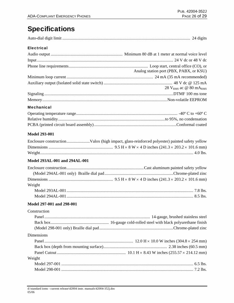
SpecificationsAuto-dial digit limit ......................................................................................................................... 24 digits
ElectricalAudio output .................................................................... Minimum 80 dB at 1 meter at normal voice levelInput ................................................................................................................................. 24 V dc or 48 V dcPhone line requirements........................................................................... Loop start, central office (CO), or
Analog station port (PBX, PABX, or KSU)Minimum loop current .................................................................................. 24 mA (35 mA recommended)Auxiliary output (Isolated solid state switch) ................................................................. 48 V dc @ 125 mA
28 VRMS ac @ 80 mARMS
Signaling ..........................................................................................................................DTMF 100 ms toneMemory......................................................................................................................Non-volatile EEPROM
MechanicalOperating temperature range................................................................................................ -40º C to +60º CRelative humidity.....................................................................................................to 95%, no condensationPCBA (printed circuit board assembly) ..............................................................................Conformal coated
Model 293-001
Enclosure construction......................Valox (high impact, glass-reinforced polyester) painted safety yellowDimensions ............................................................. 9.5 H × 8 W × 4 D inches (241.3 × 203.2 × 101.6 mm)Weight................................................................................................................................................. 4.0 lbs.
Model 293AL-001 and 294AL-001
Enclosure construction.........................................................................Cast aluminum painted safety yellow(Model 294AL-001 only) Braille dial pad.................................................................Chrome-plated zinc
Dimensions ............................................................. 9.5 H × 8 W × 4 D inches (241.3 × 203.2 × 101.6 mm)Weight
Model 293AL-001........................................................................................................................ 7.8 lbs.Model 294AL-001........................................................................................................................ 8.5 lbs.
Model 297-001 and 298-001
ConstructionPanel .................................................................................................... 14-gauge, brushed stainless steelBack box....................................................... 16-gauge cold-rolled steel with black polyurethane finish(Model 298-001 only) Braille dial pad......................................................................Chrome-plated zinc
DimensionsPanel .................................................................................... 12.0 H × 10.0 W inches (304.8 × 254 mm)Back box (depth from mounting surface)............................................................ 2.38 inches (60.5 mm)Panel Cutout ................................................................. 10.1 H × 8.43 W inches (255.57 × 214.12 mm)
WeightModel 297-001 ............................................................................................................................. 6.5 lbs.Model 298-001 ............................................................................................................................. 7.2 lbs.
PUB. 42004-352JADA-COMPLIANT EMERGENCY PHONES PAGE 27 of 29
d:\standard ioms - current release\42004 instr. manuals\42004-352j.doc05/06
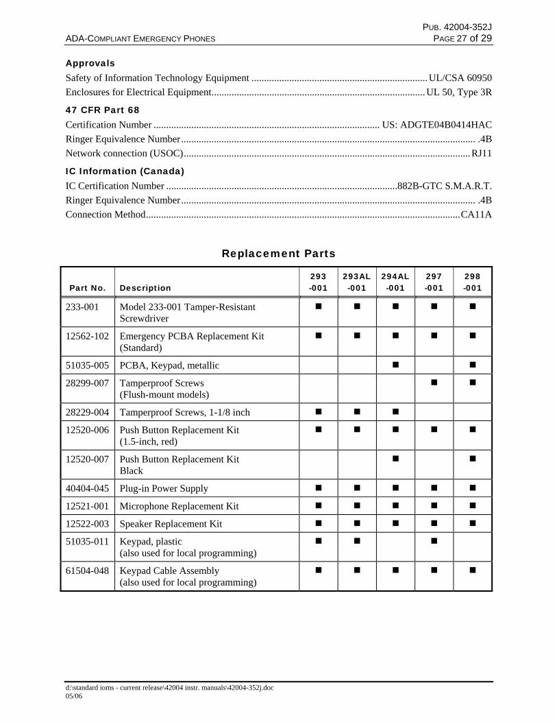
ApprovalsSafety of Information Technology Equipment ...................................................................... UL/CSA 60950Enclosures for Electrical Equipment..................................................................................... UL 50, Type 3R
47 CFR Part 68Certification Number .......................................................................................... US: ADGTE04B0414HACRinger Equivalence Number..................................................................................................................... .4BNetwork connection (USOC)..................................................................................................................RJ11
IC Information (Canada)IC Certification Number ............................................................................................882B-GTC S.M.A.R.T.Ringer Equivalence Number..................................................................................................................... .4BConnection Method.............................................................................................................................CA11A
Replacement Parts
Part No. Description293-001
293AL-001
294AL-001
297-001
298-001
233-001 Model 233-001 Tamper-ResistantScrewdriver
12562-102 Emergency PCBA Replacement Kit(Standard)
51035-005 PCBA, Keypad, metallic
28299-007 Tamperproof Screws(Flush-mount models)
28229-004 Tamperproof Screws, 1-1/8 inch
12520-006 Push Button Replacement Kit(1.5-inch, red)
12520-007 Push Button Replacement KitBlack
40404-045 Plug-in Power Supply
12521-001 Microphone Replacement Kit
12522-003 Speaker Replacement Kit
51035-011 Keypad, plastic(also used for local programming)
61504-048 Keypad Cable Assembly(also used for local programming)

PUB. 42004-352JADA-COMPLIANT EMERGENCY PHONES PAGE 28 of 29
d:\standard ioms - current release\42004 instr. manuals\42004-352j.doc05/06
User Instructions (USA)This equipment complies with Part 68 of the FCC rules and the requirements adopted by the ACTA. On thisequipment is a label that contains, among other information, a product identifier in the formatUS:AAAEQ##TXXXX. If requested, this number must be provided to the telephone company.
A plug and jack used to connect this equipment to the premises wiring and telephone network must comply with theapplicable FCC Part 68 rules and requirements adopted by the ACTA. A compliant telephone cord and modularplug is provided with this product. It is designed to be connected to a compatible modular jack that is alsocompliant. See installation instructions for details.
The REN is used to determine the number of devices that may be connected to a telephone line. Excessive RENs onthe telephone line may result in the devices not ringing in response to an incoming call. In most but not all areas, thesum of the RENs should not exceed five (5.0). To be certain of the number of devices that may be connected to aline, as determined by the total RENs, contact the local telephone company. For products approved after July 23,2001, the REN for this product is part of the product identifier that has the format US:AAAEQ##TXXXX. Thedigits represented by ## are the REN without a decimal point (e.g., 03 is an REN of 0.3). For earlier products, theREN is separately shown on the label.
If this equipment [GAI-Tronics telephone] causes harm to the telephone network, the telephone company will notifyyou in advance that temporary discontinuance of service may be required. But if advance notice isn’t practical, thetelephone company will notify the customer as soon as possible. Also, you will be advised of your right to file acomplaint with the FCC if you believe it is necessary.
The telephone company may make changes in its facilities, equipment, operations, or procedures that could affectthe operation of the equipment. If this happens the telephone company will provide advance notice in order for youto make necessary modifications to maintain uninterrupted service.
If trouble is experienced with this equipment [GAI-Tronics telephone], for repair or warranty information, pleasecontact GAI-Tronics Corporation at 800-492-1212 or www.gai-tronics.com. If the equipment is causing harm to thetelephone network, the telephone company may request that you disconnect the equipment until the problem isresolved.
Connection to party line service is subject to state tariffs. Contact the state public utility commission, public servicecommission or corporation commission for information.
User Instructions (Canada) CP-01, Issue 8, Part I: Section 14.1NOTICE: The Industry Canada label identifies certified equipment. This certification means that the equipmentmeets certain telecommunications network protective, operational and safety requirements as prescribed in theappropriate Terminal Equipment Technical Requirements document (s). The Department does not guarantee theequipment will operate to the user's satisfaction. Before installing this equipment, users should ensure that it ispermissible to be connected to the facilities of the local telecommunications company. The equipment must also beinstalled using an acceptable method of connection. The customer should be aware that compliance with the aboveconditions may not prevent degradation of service in some situations. Repairs to certified equipment should becoordinated by a representative designated by the supplier. Any repairs or alterations made by the user to thisequipment, or equipment malfunctions, may give the telecommunications company cause to request the user todisconnect the equipment. Users should ensure for their own protection that the electrical ground connections of thepower utility, telephone lines and internal metallic water pipe system, if present, are connected together. Thisprecaution may be particularly important in rural areas.
CAUTIONUsers should not attempt to make such connections themselves, but should contact the appropriate electricinspection authority, or electrician, as appropriate.
CP-01, Issue 8, Part I: Section 14.2NOTICE: The Ringer Equivalence Number (REN) assigned to each terminal device provides an indication of themaximum number of terminals allowed to be connected to a telephone interface. The termination on an interfacemay consist of any combination of devices subject only to the requirement that the sum of the Ringer EquivalenceNumbers of all the devices does not exceed 5.

PUB. 42004-352JADA-COMPLIANT EMERGENCY PHONES PAGE 29 of 29
d:\standard ioms - current release\42004 instr. manuals\42004-352j.doc05/06
Confidentiality NoticeThis manual is provided solely as an installation, operation, and maintenance guide and contains sensitivebusiness and technical information that is confidential and proprietary to GAI-Tronics. GAI-Tronicsretains all intellectual property and other rights in or to the information contained herein, and suchinformation may only be used in connection with the operation of your GAI-Tronics product or system.This manual may not be disclosed in any form, in whole or in part, directly or indirectly, to any third party.
(Rev. 1/97)
WarrantyEquipment. GAI-Tronics warrants for a period of one (1) year from the date of shipment, that anyGAI-Tronics equipment supplied hereunder shall be free of defects in material and workmanship, shallcomply with the then-current product specifications and product literature, and if applicable, shall be fitfor the purpose specified in the agreed upon quotation or proposal document. If (a) Seller’s goods proveto be defective in workmanship and/or material under normal and proper usage, or unfit for the purposespecified and agreed upon, and (b) Buyer’s claim is made within the warranty period set forth above,Buyer may return such goods to GAI-Tronics nearest depot repair facility, freight prepaid, at which timethey will be repaired or replaced, at Seller’s option, without charge to Buyer. Repair or replacement shallbe Buyer’s sole and exclusive remedy, and the warranty period on any repaired or replacement equipmentshall be one (1) year from the date the original equipment was shipped. In no event shall GAI-Tronicswarranty obligations with respect to equipment exceed 100% of the total cost of the equipment suppliedhereunder. Buyer may also be entitled to the manufacturer’s warranty on any third-party goods suppliedby GAI-Tronics hereunder. The applicability of any such third-party warranty will be determined byGAI-Tronics.
Services. Any services GAI-Tronics provides hereunder, whether directly or through subcontractors,shall be performed in accordance with the standard of care with which such services are normallyprovided in the industry. If the services fail to meet the applicable industry standard, GAI-Tronics will,for a period of one (1) year from the date of completion, re-perform such services at no cost to Buyer. Re-performance of services shall be Buyer’s sole and exclusive remedy, and in no event shall GAI-Tronicswarranty obligations with respect to services exceed 100% of the total cost of services providedhereunder.
Warranty Periods. Every claim by Buyer alleging a defect in the goods and/or services providedhereunder shall be deemed waived unless such claim is made in writing within the applicable warrantyperiods as set forth above. Provided, however, that if the defect complained of is latent and notdiscoverable within the above warranty periods, every claim arising on account of such latent defect shallbe deemed waived unless it is made in writing within a reasonable time after such latent defect is orshould have been discovered by Buyer.
Limitations / Exclusions. The warranties herein shall not apply to, and GAI-Tronics shall not beresponsible for, any damage to the goods or failure of the services supplied hereunder, to the extentcaused by Buyer’s neglect, failure to follow operational and maintenance procedures provided with theequipment, or the use of technicians not specifically authorized by GAI-Tronics to maintain or service theequipment. THE WARRANTIES AND REMEDIES CONTAINED HEREIN ARE IN LIEU OF ANDEXCLUDE ALL OTHER WARRANTIES AND REMEDIES, WHETHER EXPRESS OR IMPLIEDBY OPERATION OF LAW OR OTHERWISE, INCLUDING ANY WARRANTIES OFMERCHANTABILITY OR FITNESS FOR A PARTICULAR PURPOSE.
Return PolicyIf the equipment requires service, contact your Regional Service Center for a return authorization number(RA#). Equipment should be shipped prepaid to GAI-Tronics with a return authorization number and apurchase order number. If the equipment is under warranty, repairs or a replacement will be made inaccordance with the warranty policy set forth above. Please include a written explanation of all defects toassist our technicians in their troubleshooting efforts.
Call 800-492-1212 (inside the USA) or 610-777-1374 (outside the USA) for help identifying theRegional Service Center closest to you.