Embed Size (px)
Citation preview

Engineering Fracture Mechanics 73 (2006) 994–1008
www.elsevier.com/locate/engfracmech
A hybrid method to assess interface debondingby finite fracture mechanics
Axel Muller a, Wilfried Becker b, Detlef Stolten c, Jorg Hohe d,*
a Universitat Siegen, Institut fur Mechanik und Regelungstechnik Paul-Bonatz-Str. 9-11, 57068 Siegen, Germanyb Technische Universitat Darmstadt, Institut fur Mechanik Hochschulstr. 1, 64289 Darmstadt, Germany
c Forschungszentrum Julich, Institut fur Werkstoffe und Verfahren der Energietechnik 52425 Julich, Germanyd Fraunhofer Institut fur Werkstoffmechanik Wohlerstr. 11, 79108 Freiburg/Brsg., Germany
Received 10 August 2005; received in revised form 23 November 2005; accepted 2 December 2005Available online 24 January 2006
Abstract
Adhesive connections are potentially weak locations in many kinds of engineering structures. Since adhesive joints canbe regarded locally as bimaterial notches, the assessment of the hazard of crack nucleation, initiation and propagation inthe vicinity of bimaterial notches and the reliability of the junctions is an important problem. An essential requirement inthis context is a sufficient criterion for crack nucleation. The present contribution proposes a modified approach based onLeguillon’s hypothesis in order to provide a feasible criterion. A crack at a notch is assumed to be initiated and to grow ifand only if both the released energy and the local stresses exceed critical values. Thus, simulating virtual crack growthalong an interface of two dissimilar bonded materials, the integrity of the bond is revisable. The approach enables thedetermination of characteristic lengths for freshly nucleated cracks forming the base for any further integrity assessment.As an example, the concept is applied to the analysis of an adhesive bond of metallic and ceramic materials under severethermal loading conditions as they occur, among other examples, in high temperature fuel cell technology. It is shown thatthe failure hazard of the adhesive joint can be reduced significantly by an appropriate local design.� 2005 Elsevier Ltd. All rights reserved.
Keywords: Bimaterial notches; Finite fracture mechanics; Fracture criteria; Crack nucleation
1. Introduction
One of the oldest cultural achievements of creative and planning human beings is the attempt to connect twoparts in order to obtain one new and more suitable item. Already during the Stone Age, the hunters gluedarrow-heads or blades made from stone in the shafts of their arrows and knifes. Thus, they combined theadvantages of the tough, sharp blades with those of the light handles made from wood. The use of veneeredwood or the soldering of the ancient Egyptians are further examples, documented in early times in the
0013-7944/$ - see front matter � 2005 Elsevier Ltd. All rights reserved.
doi:10.1016/j.engfracmech.2005.12.001
* Corresponding author. Tel.: +49 761 5142 340; fax: +49 761 5142 110.E-mail address: [email protected] (J. Hohe).

Nomenclature
A, B, C, D ranges for crack nucleation, growth and arresta, b, c general, intermediate and characteristic crack lengthsda, Da crack extensionE integral of G with respect to a
Ecrit critical value of EFx, Fy components of the nodal force vectorG, GI, GII energy release ratesGcrit fracture toughnessGarrest arrest toughnessi, j, k, l node numberst thickness of the adhesive layeru, v components of the nodal displacement vector[u], [v] displacement discontinuities across the crack facesw width of the adhesive layerx, y spatial directionsuv, uI, uII notch opening angle, wetting or joining anglesrxx, ryy, rxy in-plane components of the stress tensorrcrit strengthMEA membrane electrodes assemblySOFC solid oxide fuel cell
A. Muller et al. / Engineering Fracture Mechanics 73 (2006) 994–1008 995
Theben-west tombs, approximately already 1500 BC. The question of reliability is however as old as the joiningtechniques themselves: Will the junction preserve its integrity or not? One question in this context is, whethercracks will occur in the vicinity of the joint or at the joint itself. Pliny, the Elder [23] 23–79 AC, is seen as the firstauthor in history who investigated the joining problem for wood and found that if two parts of wood are gluedtogether, the adhesive junction could be so strong that this composite splits within the wood rather than in theadhesive. Hence, the fact that the vicinity of joints or interfaces are favourite locations for the development ofcracks, was known already in ancient times.
In modern technologies, multi-component structures with a huge number of joints, junctions and connec-tions of at least two different materials are common features. Therefore, recent work on adhesive bonds placesan increasing emphasis on the mechanisms responsible for fracture. As actual applications of the investiga-tions presented here, ceramic thermal barrier coating systems or the sealings of high temperature fuel cellsshould be mentioned. Other examples are bonded joints of laminates for use in aerospace, naval or automobilestructures or soldered joints for electronics. For all these applications, particularly under thermal loading con-ditions, the regions in the vicinity of material and geometrical discontinuities belong to the most critical loca-tions of the respective components.
The integrity assessment of bimaterial joint situations may be performed based on the asymptotic localfields similar to the standard approach in fracture mechanics. At bimaterial wedges, the local stress fields exhi-bit a singular behavior which differs from the crack tip singularity in the order and depends on geometry andmaterial combination. In general, this leads to non-separable singular fields (see e.g. Muller et al. [17,19]).Since the order of the singularity varies with geometry and material properties, no simple assessment basedon the local asymptotic fields as usual in fracture mechanics can be performed.
The present study addresses this problem using the concept of finite fracture mechanics, originally intro-duced by Hashin [4]. This concept provides a pragmatic possibility for the assessment of various geometriesbased on the assumption that cracks of finite length are initiated during a very short incident. The hybridmethod presented here can be characterized as a combination of two common criteria, a stress-based one, usu-ally applied in structural mechanics, and an energy-based criterion, derived from fracture mechanics. In thiscontext, the crack is assumed to be initiated and to grow if and only if both the released energy and the local

996 A. Muller et al. / Engineering Fracture Mechanics 73 (2006) 994–1008
stress simultaneously reach critical values. The concept makes use of the hypothesis of Leguillon [13] in a mod-ified manner. As an example, a bimaterial interface configuration of a thin ceramic layer on a substrate underthermal loading conditions is considered, as required for thermal carrier coating systems or modern high tem-perature solid oxide fuel cell (SOFC) stacks. Herein, simulating virtual crack growth along an interface, theintegrity of the joint is revisable and finite characteristic crack lengths can be determined and assessed.
2. Literature overview
According to Leguillon [13], the answer to the question whether stress concentrations at joints like bima-terial wedges or notches lead to the initiation of cracks is an open question, especially, if the investigation hasto be performed without the a priori assumption of flaws or pre-existent cracks, as been performed e.g. byLeblond and Mouro [8] or Leguillon et al. [9]. Since none of the established criteria, whether stress-basedor energy-based, allows a sufficient and reliable statement on the criticality of a junction on its own, Oduleyeet al. [22] and Leguillon [13] propose an alternative approach, combining the two individual criteria to a singleone.
Alternatively, other methods for the assessment of notch situations without pre-existing cracks in homoge-neous material or at interfaces have been proposed. Extensive overviews on this topic have been provided byNairn [21], Leguillon and Yosibash [14], as well as by Yosibash et al. [27]. The direct transfer of the conceptsof linear elastic fracture mechanics to the bimaterial notch situation consists in an assessment using the expo-nents and the generalized stress intensity factor governing the singular asymptotic fields. In this sense, Dunnet al. [2,3] and Labossiere et al. [7] provided a concept which is based on the evaluation of the underlying stressfields only. Herein, generalized stress intensity factors are used as sole parameters. The corresponding criticalvalues are determined experimentally for each individual notch or wedge situation and for each material orinterface combination (see Suwito et al. [25,26]). Yosibash et al. [27] state that this method could scarcelybe generalized for mixed-mode cases. Furthermore, they characterize the units of the critical stress intensityfactors as ‘‘somewhat entangled’’ and remark on the difficulties of the utilization of the physically correctvalue of strength or fracture stress.
On the other hand, Leguillon [12,13], Leguillon et al. [11] and Abe et al. [1] propose their idea to predict theinitiation of cracks at sharp notches in homogeneous material (see also Martin et al. [16] and Jensen [6]). Theirhypothesis is based on both criteria, an energy criterion and a stress based one. According to this approach,both criteria have to be satisfied simultaneously. If this is the case, a discrete crack with a characteristic lengthin the sense of finite fracture mechanics, introduced by Hashin [4] in 1996, may be nucleated instantaneously.In contrast to the conventional practice of fracture mechanics which assumes infinitesimal crack growth, theconcept of finite fracture mechanics can be regarded as more realistic, since, according to Nairn [20], cracks offinite length are nucleated during a very short period of time (see also Leguillon [10]). A generalization of thisconcept is adopted in the present study.
3. Failure assessment of bimaterial notches
As a first step in the analysis of bimaterial joints, the simulation of hypothetical cracks is required. Con-sidering virtual crack growth along the interfaces, the strain energy release rate can be calculated numerically.Conventionally, the symbol G denotes the energy release rate. The critical energy release rate defining thematerial’s resistance to crack growth is denoted by Gcrit.
The calculation of energy release rates can be performed by several methods. In the present study, the vir-tual crack closure integral according to Irwin [5] is employed. Thus, the energy release rates for the crack open-ing modes I and II are given by
GI ¼ limDa!0
1
2Da
Z Da
0
ryy ½v�dx ð1Þ
GII ¼ limDa!0
1
2Da
Z Da
0
rxy ½u�dx ð2Þ

A. Muller et al. / Engineering Fracture Mechanics 73 (2006) 994–1008 997
where ryy and rxy are the crack closing and shear stress components, whereas [u] and [v] denote the displace-ment discontinuities across the crack faces in the x- and y-directions respectively. For numerical evaluation,the approximate scheme by Rybicki and Kanninen [24] is employed. The integrals are determined by the nodalreaction forces and displacements which are obtained directly from the output of a corresponding finite ele-ment analysis. In the direction of the hypothetical crack growth, a double row of nodes tied together is placedfor the simulation of the growing crack (see Fig. 1). The energy release rates are given by
GI ¼1
2DaF ðiÞ
y vðkÞ � vðlÞ� �
ð3Þ
GII ¼1
2DaF ðiÞ
x uðkÞ � uðlÞ� �
ð4Þ
where the indices in brackets refer to the node numbers. In this context, nodes i and j form the actual crack tipwhereas nodes k and l are situated on the crack faces next to the crack front (see Fig. 1). As usual, the indices Iand II indicate the respective crack opening modes. For a crack extension of Da as shown in Fig. 1, GI for theopening mode I is calculated from the vertical reaction force F ðiÞ
y of the node i (which is tied to node j) and therelative displacements v(k) and v(l) of the nodes k and l in vertical (y-) direction caused by the crack propaga-tion. In analogy, the energy release rate GII for the sliding mode II is determined by the reaction force F ðiÞ
x andthe relative displacements u(k) and u(l) in the horizontal direction. These two components taken together rep-resent the total energy release rate G. Simulating crack growth, the nodes i and j have to be untied step by step,when the crack is extended virtually in each single step by an additional length Da.
Using this procedure implies that the crack path is pre-defined. Nevertheless, in many structural examples,the potential crack path can be determined a priory, at least for the initial range of possible crack propagation.Especially for interface crack problems, the crack path is known for most cases, since, in general, the interfacetoughness is much lower than the toughnesses of the bonded materials. Hence, the requirement of a pre-defined crack path does not constitute a limitation for the present method as long as it is applied to interfaceproblems as considered in the present study.
Two common criteria for the assessment of interface crack onset at notches exist side by side: a stress-basedand an energy-based criterion. The stress-based criterion predicts fracture if the maximum value of the inter-face tensile stress exceeds the interface strength
ryy P rcrit ð5Þ
The critical stress rcrit can be either the failure stress determined in a one-dimensional tensile experiment orany other appropriate stress level defining a failure load level in the absence of stress concentrations. Dueto the singular stress field in the bimaterial notch situation considered here, the material or the interfacestrength is always exceeded in some region close to the notch root. Thus, according to the strength criterionfracture should occur in any case, even if the load is very small. On the other hand, although a notch is a priv-ileged location for crack initiation, obviously not every small load applied at a notch causes fracture.The energy-based criterion predicts fracture if the energy release rate G exceeds its critical value, the tough-ness Gcrit
G P Gcrit ð6Þ
Fig. 1. Calculation of energy release rates for virtual crack growth.

998 A. Muller et al. / Engineering Fracture Mechanics 73 (2006) 994–1008
In terms of Eq. (6) the toughness of the interface and of the joined materials is taken into account. Assuming agiven situation with a notch without any initial crack, the energy release rate is zero. Thus, according to theenergy criterion in the given infinitesimal form, no crack nucleation would ever be predicted. Nevertheless,notches are critical locations for crack formation.
In order to derive a more satisfying predictive concept for fracture, the concept of finite fracture mechanicsintroduced by Hashin [4] is adopted. It considers the hypothetical instantaneous onset of cracks of finitelength. It is analyzed whether such cracks are possible from both points of view, exceeded strength and suf-ficient energy released. In accordance to Leguillon’s hypothesis [13], the two criteria together form a sufficientcondition for fracture. Satisfying both the strength and the toughness criterion simultaneously, a characteristiclength of crack nucleation can be determined. In this case, the total energy E released for the hypotheticalcrack of length a has to exceed the integrated fracture toughness
E P Ecrit with E ¼Z a
0
Gda and Ecrit ¼ aGcrit. ð7Þ
This hybrid method is a novel approach which combines the two conventional approaches of assessment: Thestress-based one applied within continuum mechanics and the energy-based one from fracture mechanics.Thus, both competitive methods can be brought together and lead to a more satisfactory approach. In thiscontext it should be noted that the energy criterion is a global criterion which has to be evaluated only once.The strength criterion on the other hand is a local criterion which has to be evaluated multiple times for allpossible crack tip locations since the singular stress field propagates with the advancing crack tip. This fact willbe discusesed in more detail in the application example presented in Section 6.
4. Example for application and numerical model
As an example for application, a solid oxide fuel cell (SOFC) stack is considered in this investigation. It ischaracterized by a planar, anode supported design. The membrane electrodes assembly (MEA), representingthe functional layers anode, electrolyte and cathode is a sintered composite consisting of three layers of cera-mic materials. The anode layer is a thick porous cermet, whereas the electrolyte is a thin film with a thicknessof about 1/150 of the anode thickness. The cathode is a thin porous ceramic layer. Even a slight mismatch ofthe individual sintered layers of the MEA in their thermal expansion properties leads to highly stressed joiningareas since the assembly experiences high temperature loads up to DT = 800 �C. Further stresses are inducedby the different shrinkage of the materials during sintering (see Muller et al. [18] for details).
Within the fuel cell stack, the MEAs are embedded into interconnect frames made from metallic materials,usually structural steel. The interface between interconnect and MEA is sealed with a glass ceramic material(see Fig. 2). The task of the sealing is twofold. From the structural mechanics point of view, it has to keep thetwo components together and to transmit the residual cross sectional forces resulting from the different ther-mal expansion of MEA and interconnect as well as from the thermal bending of the membrane electrodesassembly. From the electrochemical point of view, the integrity of the sealing is an essential feature, sincethe sealing separates the oxygen flow from the fuel and has to guarantee gas tightness.
Fig. 2. Ceramic high-temperature fuel cell stack (not to scale).

Fig. 3. Adhesive joint considered as a bimaterial notch.
A. Muller et al. / Engineering Fracture Mechanics 73 (2006) 994–1008 999
Focussing the investigations on the sealings, these junctions are scrutinized as they are seen to belong to themost critical regions of the whole SOFC-stack. As Fig. 3 illustrates, the local stress concentration regions canbe idealized as bimaterial notches. The structural mechanical assessment of these bimaterial notch situations isthe objective of the present study. The analyses are based on the assumption of isotropic, linear-elastic behav-ior of all involved materials. The local stress fields in the vicinity of the notch roots exhibit a singular asymp-totic behavior. The order of the singularity at the bimaterial notch differs from the well-known square-rootcrack tip singularity. The singularity exponent is affected by the geometry and the material combination. Sim-ulating the initiation of hypothetical cracks and their virtual growth along the bimaterial interfaces, the crit-icality of potential cracks can be estimated.
In order to assess a virtual potential crack along the interfaces between the glass ceramic sealing and theinterconnect or the electrolyte layer respectively, a characteristic lay-up of a SOFC-stack is chosen for the sim-ulation by finite element analysis as shown in Fig. 2. The simulations are performed for a thermal load wherethe fuel cell stack is cooled down from the service temperature (T = 800 �C) to room temperature (T = 20 �C).The investigations are focussed on crack growth directly along the interface. Although, especially in morecomplex mechanical loading situations potential cracks may grow into different directions, the interface itselfis assumed to be the most critical region, since in many cases the interface toughness is lower than the fracturetoughness of the joined materials (see e.g. experimental studies by Malzbender et al. [15]). The considereddirections of crack nucleation and propagation are presented in Fig. 4.
The problem is analyzed numerically by means of the finite element method using standard 4-node displace-ment based elements. For reasons of numerical efficiency, a simplified two-dimensional model under the
Fig. 4. Geometry of the sealing structure and conceivable virtual crack positions (not to scale).

Fig. 5. Typical layout of the finite element mesh in the vicinity of the sealing joint.
1000 A. Muller et al. / Engineering Fracture Mechanics 73 (2006) 994–1008
assumption of plane strain conditions is employed. Along the lower edge of the interconnect, no vertical dis-placements are permitted, whereas along a vertical line at the center of the sealing joint, the horizontal dis-placements are suppressed for symmetry reasons. Different geometries of the sealing are considered,especially for the wetting conditions governing the notch opening angle at the respective interface betweenglass ceramic sealing and base material. A typical mesh layout in the vicinity of the sealing joint is presentedin Fig. 5. In this case, the finite element model consists of 55647 elements with a total of 56574 nodes and thus113148 degrees of freedom. In the fracture process zones in the glass ceramic sealing, a regular mesh layoutconsisting of rectangular elements with edge lengths of 0.0125 mm in the x-direction and 0.01 mm in the y-direction is chosen. Outside this range, a gradually coarsening mesh layout is adopted. The element edgelength in the x-direction at the interfaces between the glass ceramic sealing and the adjacent material rangesdefines the minimum crack length increment Da that can be considered.
As a reference case for the discussion of the sealing design, the case of a notch angle uII = 90� (see Fig. 3), ajoint width of w = 10 mm and a joint thickness of t = 0.25 mm is chosen. The crack is assumed to emanatefrom the top left corner of the adhesive layer as indicated in Fig. 4.
5. Energy release rates of virtual cracks along the interfaces
As a first step towards the application of the hybrid criterion described in Section 3, the energy release ratesfor a virtual crack growth along the interface are computed. The results for the reference case mentioned inSection 4 are presented in Fig. 6. A remarkable fact is that both the energy release rate GI for mode I as well asthe energy release rate GII for mode II and thus also the total energy release rate
Fig. 6. Energy release rate considering virtual crack growth for the reference case.

Fig
A. Muller et al. / Engineering Fracture Mechanics 73 (2006) 994–1008 1001
Gtot ¼ GI þ GII ð8Þ
reach their respective maximum for rather short virtual crack lengths (GI: 0.2 mm, GII: 0.25 mm). For longercracks, both energy release rates decrease sharply towards low levels tending asymptotically towards zero.This graph supports the assumption that a crack starting at a geometrical discontinuity will not lead to cat-astrophic failure of the interface under exclusively thermal loading situations. If cracks could be initiated froma critical energy release rate of G � 0:01 N=mm and assuming for simplicity that the fracture toughness Gcritfor crack initiation and crack arrest were identical, cracks would not propagate along the complete interface,but would be expected to arrest at a crack length a < 1 mm. At this point, the graph of the energy release ratedecreases steeply below its critical value.
The maximum value of the sliding (mode II) component GII is found approximately five times higher thecorresponding value GI of the opening mode. Thus, the sliding mode dominates the energy release rate due tothe mismatch in the coefficients of thermal expansion and, accordingly, due to the shear stress at the interface.This effect is caused by the mismatch in the coefficients of thermal expansion of the bonded materials. Thethermal expansion coefficient of the interconnect material is larger than that of the glas-ceramic sealing. Thus,during the cooling process, the interconnect tends to shrink more than the sealing inducing shear stresses at theinterface.
Fig. 7 illustrates the effect of the joining angle. Apart from the reference case (uII = 90�), further situationsas examples of improved wetting conditions with uII = 30� and uII = 60� as well as worse wetting conditions(uII = 120�) are considered. In analogy to the reference case discussed above, GII dominates again, but fromnow on the two modes are presented together in the form of Gtot only. Whereas the maximum of the energyrelease rate grows with increasing joining angles, its distance from the wedge centre decreases with increasingjoining angles. The angle is related to the interface. Thus, small angles improve the wetting situation and con-sequently a geometrically smoother transition of the materials leads to lower values of the energy release rate.The maximum energy release rates vary between G � 0:027 N=mm for large joining angles and G �0:022 N=mm for improved wetting situations, correlating to a reduction of 20%. Thus, the tendency of crackinitiation is reduced for the better wetting situations, though the effect is not as strong as that of reducing thejoint thickness as shown below.
An interesting effect at the onset of virtual crack growth is the initially concave nature of the GtotðaÞ crackresistance curves in the presence of small joining angles, especially in the case with uII = 30�. For small joiningangles, only small amounts of energy are released since only a small amount of sealing material is situateddirectly below the interface as long as the crack is rather short due to the notch like geometry of the sealingboundary (see also the sketch on the right hand side of Fig. 4). With increasing virtual crack length, an increas-ing amount of sealing material is located in the vicinity of the crack tip resulting in the progressive increase ofthe crack resistance curve. Once the crack tip has passed the deepest position of the notch in the left end of thesealing, the standard behaviour observed is recovered.
Another observation is that for large joining angles uII = 120� the maximum value of the energy release rateis reached at a = 0.15 mm virtual crack length only. For the smooth joint with uII = 30�, this value is doubled
. 7. Energy release rate for various wetting conditions. Magnification of the range of the maxima of the energy release rates.

Fig. 8. Dependence of the energy release rate on the joint thickness.
1002 A. Muller et al. / Engineering Fracture Mechanics 73 (2006) 994–1008
to a = 0.3 mm. This fact may be more significant than the level of released energy itself, since small localdefects like inclusions or pores can be interpreted as cracks which cause a large quantity of released energyin situations of insufficient wetting. For smooth joints the high level of the energy release rate is reached onlyin the case of essentially larger inhomogeneities. Therefore, the smoother the joint is, the higher is the tolerancewith regard to small defects which cannot be avoided during the joining process.
Regarding the dependence of the energy release rate G on the joint width w no significant effect is observed.The extrema calculated for several joint widths are reached more or less at the same virtual crack length a andpossess about the same maximum value Gmax. Hence, the study concentrates on the influence of the joint thick-ness t on the energy release rate. The results of this analysis are presented in Fig. 8. In addition to the referencecase (t = 0.25 mm), three examples with reduced (t = 0.125 mm) and increased (t = 0.5 mm, t = 1 mm) jointthickness are considered. The significant effect is the almost proportional dependence of the maximum valuesGmax of the energy release rates on the joint thickness t. With thicker joints, the maximum values of the energyrelease rates increase significantly. Starting from the reference case, all the joints thicker than t = 0.25 mmreach critical values of the energy release rate. As a consequence, the joining areas should be designed suchthat the adhesive layers themselves are made as thin as possible since thicker joints tend to provoke failure.
6. Assessment of interface debonding
As pointed out before, the assessment of interface debonding in terms of energy release rates only is notsufficient. On the other hand, based on the analysis of a virtual crack growth, an assessment of the differentjoining can be performed using the hybrid approach described in Section 3. Failure of the whole interface isassumed, if no crack arrest can be determined, so that the crack is expected to grow along the entire interface.For that aim, the distribution of the interface opening stress ryy and the total released energy E for a virtualcrack propagating along the interface are examined. The analysis is performed for all four of the differentinterfaces shown in Fig. 4 as well as for different joint geometries. The results are presented in Figs. 9 and11–14. For comparison, the results of the reference case are given at the top left position in all subsequentfigures.
Applying Leguillon’s hypothesis to the SOFC-stack, first of all the reference geometry is investigated. Fig. 9contains the resulting curves on the top left position of the adhesive layer corresponding to the interfacebetween the glass ceramic sealing and the interconnect frame. Four ranges can be distinguished: In a rangeA, only the strength criterion is satisfied. Together with the following range B, where both the strength andthe toughness criteria are satisfied simultaneously, crack nucleation is predicted in the sense of finite fracturemechanics. Up to a crack length b, the admissible stress rcrit is exceeded and, simultaneously, the amount ofthe energy released surpasses its critical value Ecrit. Consequently, a crack with a finite length b is nucleateddue to the singular stress field at the underlying 90� bimaterial notch and due to the fact that enough energyis available.
During the subsequent range C, the energy necessary for fracture is available furtheron. The singular stressfield propagates with the extending crack as indicated in Fig. 9. Hence, though the energy criterion is global,

Fig. 9. Effect of the virtual crack position on the criticality of the investigated interfaces.
A. Muller et al. / Engineering Fracture Mechanics 73 (2006) 994–1008 1003
the strength criterion has to be evaluated repeatedly for all possible positions of the crack tip. Throughoutrange C, both criteria are satisfied, representing a range of unstable crack growth. Crack arrest is expectedin range D, where the energy required for crack propagation is no longer available, though the strength stillexceeds its critical value rcrit locally. For simplicity, it is assumed that the initiation and the arrest toughnessesare equal. Nevertheless, all subsequent considerations can be performed in a similar manner under theassumption of an arrest toughness Garrest ¼ oEcrit=oa < Gcrit. Under the assumption of equal initiation andarrest toughnesses, a crack which stops at a characteristic length of c � 1 mm has to be expected at the refer-ence interface at the top left position of the adhesive layer.
Referring to Fig. 4, the interfaces are named according to their position. For cracks at the top right and thebottom left position the graphs show a behavior similar to the reference interface at the top left position. Thecharacteristic crack length predicted is about c � 0.5, . . . , 1.0 mm and all the cracks are supposed to stop at thischaracteristic length. At the bottom right position, the interface between the electrolyte layer and the glassceramic sealing is considered. As seen in Fig. 9, the strength criterion is exceeded at every virtual crack length.Within the crack nucleation range B*, this is due to the singular stress field in the vicinity of the bimaterialnotch. Subsequently, it is caused by the crack tip singularity at the moving crack tip. However, since theenergy criterion is not satisfied simultaneously, the energy release is insufficient for fracture. Thus, only oneof the necessary criteria for fracture is satisfied. For that reason, no crack nucleation is predicted. Therefore,the bottom right interface of the reference geometry is regarded as not critical. This is confirmed by the sec-tional view of the right hand side of the joint, depicted in the micrograph in Fig. 10. Here, the interfacebetween the glass ceramic sealing and the interconnect at the top right position is cracked, whereas the inter-face between the glass ceramic material and the electrolyte remains intact. As two ceramic materials are con-nected at this interface, the interface toughness Gcrit is higher than the corresponding toughness of the interfacebetween the dissimilar metallic interconnect and the ceramic glass.
The position of the boundaries of the ranges A, B, C and D and thus the behaviour of possible interfacecracks strongly depend on the respective critical load levels Ecrit and rcrit, especially on their ratio. Further-more, the angle between the graphs of E and Ecrit in the vicinity of the boundary between regions A and B
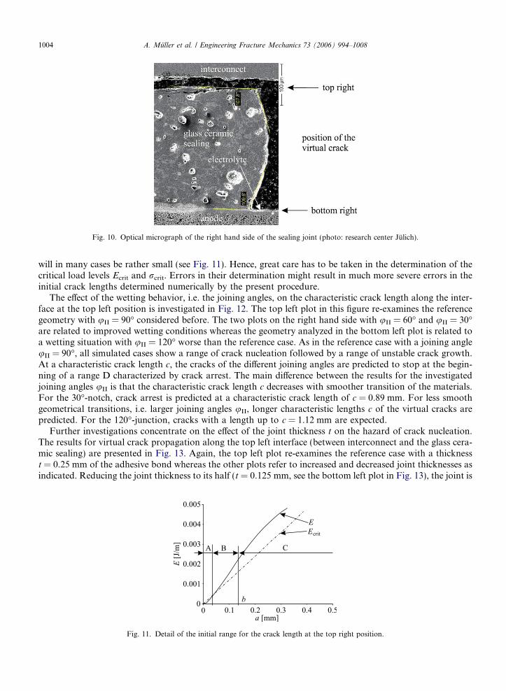
Fig. 10. Optical micrograph of the right hand side of the sealing joint (photo: research center Julich).
1004 A. Muller et al. / Engineering Fracture Mechanics 73 (2006) 994–1008
will in many cases be rather small (see Fig. 11). Hence, great care has to be taken in the determination of thecritical load levels Ecrit and rcrit. Errors in their determination might result in much more severe errors in theinitial crack lengths determined numerically by the present procedure.
The effect of the wetting behavior, i.e. the joining angles, on the characteristic crack length along the inter-face at the top left position is investigated in Fig. 12. The top left plot in this figure re-examines the referencegeometry with uII = 90� considered before. The two plots on the right hand side with uII = 60� and uII = 30�are related to improved wetting conditions whereas the geometry analyzed in the bottom left plot is related toa wetting situation with uII = 120� worse than the reference case. As in the reference case with a joining angleuII = 90�, all simulated cases show a range of crack nucleation followed by a range of unstable crack growth.At a characteristic crack length c, the cracks of the different joining angles are predicted to stop at the begin-ning of a range D characterized by crack arrest. The main difference between the results for the investigatedjoining angles uII is that the characteristic crack length c decreases with smoother transition of the materials.For the 30�-notch, crack arrest is predicted at a characteristic crack length of c = 0.89 mm. For less smoothgeometrical transitions, i.e. larger joining angles uII, longer characteristic lengths c of the virtual cracks arepredicted. For the 120�-junction, cracks with a length up to c = 1.12 mm are expected.
Further investigations concentrate on the effect of the joint thickness t on the hazard of crack nucleation.The results for virtual crack propagation along the top left interface (between interconnect and the glass cera-mic sealing) are presented in Fig. 13. Again, the top left plot re-examines the reference case with a thicknesst = 0.25 mm of the adhesive bond whereas the other plots refer to increased and decreased joint thicknesses asindicated. Reducing the joint thickness to its half (t = 0.125 mm, see the bottom left plot in Fig. 13), the joint is
Fig. 11. Detail of the initial range for the crack length at the top right position.

Fig. 12. Effect of the wetting behavior (joining angle uII) on the failure hazard.
A. Muller et al. / Engineering Fracture Mechanics 73 (2006) 994–1008 1005
predicted to be significantly more resistant to crack nucleation. Whereas for the reference configuration crackswith a finite characteristic length are expected, no crack nucleation is predicted here, as the energy criterion is
Fig. 13. Effect of the joints thickness t on the failure hazard.

Fig. 14. Effect of the joint width, i.e. the joining angle, on the criticality of the reference case.
1006 A. Muller et al. / Engineering Fracture Mechanics 73 (2006) 994–1008
never satisfied. Thus, the energy required for the creation of new crack surfaces is not available for any virtualcrack length a.
In the same manner, thicker joints do not improve the junction, as the graphs on the right hand side ofFig. 13 demonstrate where joints with a thickness of t = 0.5 mm and t = 1 mm respectively are analyzed. Thesejoining situations belong to the most critical configurations investigated within this work. From the beginningof the virtual crack growth, both the strength and the toughness criteria are satisfied simultaneously. Thestrength criterion is satisfied because of the singular stress fields in the vicinity of the underlying 90�-bimaterialnotch. Together with the simultaneously exceeded critical value of the released energy, a sufficient conditionfor crack nucleation is met. A crack is nucleated and is expected to grow along the interface. Since the nucle-ated cracks will grow as long as the required energy is available, no crack arrest is expected. Over the inves-tigated range up to half of the joint width (5 mm) no section point between the curve of the released energy E
and its critical value Ecrit could be observed.A final investigation is concerned with the effect of the joint width w on the hazard of interface crack nucle-
ation. The results are presented in Fig. 14. In addition to the reference case with a width of w = 10 mm re-examined in the top left plot of this figure, two alternative cases with w = 12 mm and w = 14 mm are analyzed.The curves of the wider joints exhibit a rather similar behavior as in the reference case with w = 10 mm. Alongthe considered interface, cracks are likely to be nucleated, but are in all cases predicted to be arrested at a char-acteristic crack length of approximately c � 1 mm. Almost no influence of the joint width w on the character-istic crack length c could be observed. Thus, the choice of wider joints does not reduce the hazard of cracknucleation.
7. Conclusion
The present study is concerned with a failure assessment of interface debonding of adhesive joints. Asymp-totically, adhesive joints can be regarded as bimaterial notches where one material is the base material of thebonded components whereas the adhesive material forms the second material. The notch opening angle as well

A. Muller et al. / Engineering Fracture Mechanics 73 (2006) 994–1008 1007
as the orientation of the interface with respect to the notch depend on the geometry of the bonded componentand on the wetting behavior of the adhesive material.
To assess this problem, the standard methods of fracture mechanics are not directly applicable. The notchopening angle between the adhesive and the base materials is, in general, much larger than zero. Hence, thegeometry under consideration deviates significantly from the geometry of a pre-cracked bimaterial with zeronotch opening angle. On the other hand, the fracture mechanics assessment of the given geometry based onassumed physically and geometrically long cracks emanating from the notch root, as it would be the standardprocedure of fracture assessment, might yield inaccurate results due to the small dimensions of the problem.
As an alternative, a hybrid method for assessment is proposed. This approach utilizes Leguillon’s hypoth-esis assuming that for crack nucleation at notches, two criteria have to be satisfied ensuring that both theactual stresses as well as the energy release exceed the corresponding strength and toughness limits. In addi-tion, the principles of finite fracture mechanics are adopted, assuming the instantaneous occurrence of crackswith a finite length during short term incidents.
The approach is applied to the assessgment of glass ceramic sealing joints as they are used in solid oxide fuelcell stacks. The sealing joints experience severe thermal stresses due to the high service temperature of the solidoxide fuel cell. Along the interface between the adhesive material and the respective base material, three dif-ferent zones can be identified. A nucleation zone, where both criteria are satisfied, is—in general—observedclose to the notch root. The nucleation zone is followed by a propagation zone, where unstable propagationof a freshly nucleated interface crack would occur. Since the total strain energy due to thermal stressing causedby thermal mismatch and a prescribed jump in the overall temperature is finite, the propagation zone is fol-lowed by an arrest zone, where the toughness criterion is no longer satisfied resulting in the arrest of cracksinitiated in the nucleation zone.
The presence and the extent of the different zones, especially the propagation zone strongly depend on thelocal joint geometry in terms of the notch opening angle, the dimensions of the adhesive layer, especially itsthickness as well as on the properties of the combined adhesive and base materials. For any specific configu-ration, the characteristic length of a freshly nucleated crack can be obtained as the distance between the notchroot and the border between the propagation and the arrest zone. Since short term incidents such as overload-ing, external impacts during handling of the system etc. leading to instantaneous nucleation of cracks in thenucleation zone cannot be avoided, cracks of this characteristic length have to be expected in the respectiveinterface. Cracks with this characteristic length have to be considered in a subsequent fracture mechanicsassessment of the respective component with respect to initiation under loads other than the nucleation loadsand especially with respect to a possible fatigue crack propagation.
Hence, the present study provides a tool for determining an appropriate starting point for a further struc-tural integrity assessment. Beside that, as it was shown in the parameter studies concerning a specific problem,the failure hazard of the adhesive joint may be reduced significantly or even entirely extinguished by an appro-priate design of the adhesive joint and the bonded components. In this context, the methods presented in thecurrent contribution can be employed as a powerful tool towards the design of failure resistant adhesive jointsunder consideration of the respective geometric and loading conditions.
Acknowledgements
The work presented in the present contribution has been perfomed at Siegen University under contract ofForschungszentrum Julich (Julich Research Center, FZJ). The financial support and the encouragement of theproject partners from Forschungszentrum Julich are gratefully acknowledged.
References
[1] Abe S, Kageyama K, Ohsawa I, Kanai M, Kato T. Analytical prediction and experiment of transverse lamina cracking inmultidirectionally reinforced symmetric laminates. In: Proc 7th Japan international SAMPE symposium and exhibition—informationand innovation in composites technologies; 2001. p. 817-02.
[2] Dunn ML, Suwito W, Cunningham S, May CW. Fracture initiation at sharp notches under mode I, mode II and mild mixed modeloading. Int J Frac 1997;84:367–81.

1008 A. Muller et al. / Engineering Fracture Mechanics 73 (2006) 994–1008
[3] Dunn ML, Suwito W, Cunningham S. Fracture initiation at sharp notches: correlation using critical stress intensities. Int J SolidsStruct 1997;34(29):3873–83.
[4] Hashin Z. Finite thermoelastic fracture criterion with application to laminate cracking analysis. J Mech Phys Solids1996;44(7):1129–45.
[5] Irwin GR. Analysis of stresses near the end of a crack traversing a plate. J Appl Mech 1957;24(3):361–4.[6] Jensen HM. Crack initiation and growth in brittle bonds. Eng Fract Mech 2003;70:1611–21.[7] Labossiere PEW, Dunn ML, Cunningham SJ. Application of bimaterial interface corner failure mechanics to silicon/glass anodic
bonds. J Mech Phys Solids 2002;50:405–33.[8] Leblond JB, Mouro P. Crack propagation from a pre-existing flaw at a notch root I: Introduction and general form of the stress
intensity factors at the initial crack tip. Int J Fract 2000;105:211–24.[9] Leguillon D, Lacroix C, Martin E. Interface debonding ahead of a primary crack. J Mech Phys Solids 2000;48:2137–61.[10] Leguillon D. Asymptotic analysis of a spontaneous crack growth—application to a blunt crack. In: Durban D, Pearson JRA, editors.
IUTAM symposium on analytical and computational fracture mechanics of non-homogeneous materials, vol. 21; 1999. p. 169–80.[11] Leguillon D, Siruguet K. Finite fracture mechanics—application to the onset of a crack at a bimaterial corner. In: Durban D, Pearson
JRA, editors. IUTAM symposium on analytical and computational fracture mechanics of non-homogeneous materials, vol. 21; 2001.p. 11–8.
[12] Leguillon D. A criterion for crack nucleation at a notch in homogeneous materials. Comptes Rendus de l’Academie des Sciences,Paris, Serie IIb 2001;t. 329:97–102.
[13] Leguillon D. Strength or toughness? A criterion for crack onset at a notch. Eur J Mech A/Solids 2002;21:61–72.[14] Leguillon D, Yosibash Z. Failure at corners in brittle materials—validation of a criterion. In: Bodner SR, Rittel D, editors. Proc 9th
int conf on the mechanical behavior of materials, ICM 9; 2003.[15] Malzbender J, Steinbrech RW, Singheiser L. Determination of the interfacial fracture energies of cathodes and glassceramic sealants
in a planar solid-oxide fuel cell design. J Mater Res 2003;4(18):929–34.[16] Martin E, Leguillon D, Lacroix C. An energy criterion for the initiation of interface failure ahead of a matrix crack in brittle matrix
composites. Comp Interf 2002;9(2):143–56.[17] Muller A, Hohe J, Becker W. Material- und Geometrieabhangigkeit der Spannungssingularitaten an Bimaterialkerben. In: Richard
HA, editor. Fortschritte in der Bruch- und Schadigungsmechanik. DVM-Report 234; 2002. p. 109–18.[18] Muller A, Hohe J, Goswami S, Becker W. Thermal effects on fracture initiation at bimaterial notches. In: Librescu L, Marzocca P,
editors. Proc 5th international congress on thermal stresses and related topics, Blacksburg VA; 2003. MA-7–4–1.[19] Muller A, Hohe J, Becker W. A closed form analysis of material and geometry effects on stress singularities at unsymmetric bimaterial
notches. Proc Appl Math Mech 2003;2:210–1.[20] Nairn JA. Application of finite fracture mechanics for predicting fracture events in composites. In: 5th international conference on
deformation and fracture; 1999.[21] Nairn JA, Matrix microcracking in composites. In: Talreja R, Manson JA, editors. Polymer matrix composites, comprehensive
composite materials, vol. 2; 1999. p. 403–32.[22] Oduleye OO, Penn SJ, Mc Alford N. The mechanical properties of (Bi–Pb)SrCaCuCo. Superconductor Sci Technol 1998;11:858–65.[23] Pliny, the Elder (Caius Plinius Secundus), Naturalis historiae, libri XVI. 23–79 AC.[24] Rybicki EF, Kanninen MF. A finite element calculation of stress intensity factors by a modified crack closure integral. Eng Fract
Mech 1977;9:913–38.[25] Suwito W, Dunn ML, Cunningham S. Fracture initiation at sharp notches in single crystal silicon. J Appl Phys 1998;83(7):3574–82.[26] Suwito W, Dunn ML, Cunningham S, Read DT. Elastic moduli, strength and fracture initiation at sharp notches in etched single
crystal microstructure. J Appl Phys 1999;85(7):3519–34.[27] Yosibash Z, Bussiba A, Gilad I. Failure criteria for brittle elastic materials. Int J Fract 2004;125:307–33.