Embed Size (px)
Citation preview

IOSR Journal of Electrical and Electronics Engineering (IOSR-JEEE)
e-ISSN: 2278-1676,p-ISSN: 2320-3331, Volume 10, Issue 3 Ver. III (May – Jun. 2015), PP 60-70
www.iosrjournals.org
DOI: 10.9790/1676-10336070 www.iosrjournals.org 60 | Page
A hybrid system based approach to Direct Torque Control (DTC)
of induction motors
Hamid Yantour1, Janah Saadi
1, Ahmed Khoumsi
2
1(Lab. of Automation and Production Engineering ENSEM, Casablanca, Morocco)
1(Lab. of Automation and Production Engineering ENSEM, Casablanca, Morocco)
2(Dept. Electrical & Computer Engineering University of Sherbrooke, Canada)
Abstract: In this paper, we study the Direct Torque Control (DTC) of an Induction Motor coupled to an
Inverter (Inv-IM). DTC permits to control directly the stator flux and the torque by selecting the appropriate
inverter state. DTC has been introduced because it presents several advantages in comparison to other
techniques such as voltage/frequency control, vector control and field control.
In this paper, we first model the DTC of Inv-IM as a hybrid system (HS). Then, we abstract the continuous
dynamics of the HS in terms of discrete events. We thus obtain a discrete event model of the HS. And finally, we
use Supervisory Control Theory of DES to drive Inv-IM to a desired working point.
Keywords: DTC, automaton, DES, Controler, IM, Inv
I. Introduction The main advantage of Induction motors (IM) is that no electrical connection is required between the
stator and the rotor. Another advantage of IMs is that they have low weight and inertia, high efficiency and a
high overload capability [1]. There exist several approaches to drive an IM. The Voltage/frequency (V/f)
controller is the simplest technique, but its main disadvantage is its lack of accuracy in both speed and torque.
Vector controllers is a technique that can reach a good accuracy, but its main disadvantages are the necessity of
a huge computational capability and of a good identification of motor parameters [2]. The method of Field
acceleration overcomes the computational problem of vector controllers by achieving some computational
reductions [3], [2], [4]. And the technique of Direct Torque Control (DTC), that has been developed by
Takahashi [5], [6], [7], [8], permits to control directly the stator flux and the torque by using an appropriate
voltage vector selected in a look-up table. The main advantages of DTC are a minimal torque response time and
the absence of: coordinate-transform, voltage modulator-block, controllers such as PID for flux and torque. For
these advantages, DTC is the control method adopted in this paper. Since the IM is driven through an inverter,
the system to be controlled consists actually of the inverter and the IM and will be denoted Inv-IM. The latter is
in fact a hybrid system, in the sense that it consists of a discrete component (the inverter) and a continuous
component (IM). We propose a three-step method to model the DTC of Inv-IM and then drive Inv-IM to a
desired working point.
• In a first step, we model the DTC of Inv-IM as a hybrid system (HS) with: a discrete event dynamics defined
by the voltage vectors used to control IM; and a continuous dynamics defined by continuous equations on the
stator flux vector ( sφ
) and the electromagnetic torque ( Γ ).
• In a second step, we abstract the continuous dynamics of the HS in terms of discrete events. Some events are
used to represent the entrance and exit of the torque Γ and the amplitude sφ of sφ
in and from a working point
region. And some other events are used to represent the passage of the vector sφ
between different zones. By
this abstraction, the continuous dynamics of the system IM is described as a discrete event system (DES).
• In a third step, we use Supervisory Control Theory (SCT) [9],[18],[19],[20] to drive Inv-IM to a desired
working point.
The remainder of the paper is structured as follows. Sect. II presents the inverter and its discrete event
dynamics. Sect. III presents the induction motor and its continuous dynamics. In Sect. IV, we propose an
abstraction of the continuous dynamics of the IM in terms of discrete events. Sect. V shows how to use SCT to
drive Inv-IM to a targeted working point. In Sect. VI, we presents simulation results and we conclude the paper
in sect VII.
II. Inverter And Its Discrete Event Model
The inverter (Fig. 1) is supplied by a voltage 0U and contains three pair of switches ( hiS , l
iS ), for i =a, b,
c. The input of the inverter is a three-bit value (SaSbSc) where each Si can be set to 0 or 1. A value 0 of Si sets

A hybrid system based approach to Direct Torque Control (DTC) of induction motors
DOI: 10.9790/1676-10336070 www.iosrjournals.org 61 | Page
( hi
S , li
S ) to (close,open), and a value 1 sets it to (open,close). The output of the inverter is a voltage vector
sV
that drives IM.
Fig.1. Inverter driving the induction motor Fig.2. the six non-null voltage vectors in the
reference frame fixed to the stator
Equation (1) computes the voltage vector sV
expressed in the α-β axes (i.e. the stationary reference
frame fixed to the stator) after Concordia transformation. Note that sV
depends uniquely on 0U and (ScSbSa).
Since 0U is fixed and (ScSbSa) can have eight different values, we expect to obtain at most 8 voltage vectors.
Actually, we have only 7 vectors, because the null vector is obtained for 000 and 111.
]eSeS[SU3
2V
)3
4π(j
c
)3
2π(j
ba0s
(1)
The correspondence between kV
and (ScSbSa) is as follows:( 0V
, 000, 111), ( 1V
, 001), ( 2V
, 011), ( 3V
,010),
( 4V
110), ( 5V
, 100), ( 6V
, 101).
The inverter can be modeled by a 7-state automaton whose each state qk (k = 0,...., 6) means: " kV
is the current
voltage vector". Since 0V
can be obtained from the inputs 000 or 111 of the inverter, the selection between the
two inputs can be done according to a specific control strategy. To adopt the terminology of hybrid systems, the
term mode will be used as a synonym of state. The transition from any mode q⋆ to a mode qk occurs by an event
kV which means "starting to apply kV
".
III. Induction Motor And Its Continuous Model The induction motor is a continuous system because its behavior is modeled by algebraic and
differential equations on two continuous variables: the stator flux sφ and the electromagnetic torque . For
conciseness, by flux we mean stator flux, and by torque we mean electromagnetic torque.
III.1 Model Of Flux And Torque
With DTC, the voltage vector sV
generated by the inverter is applied to the IM to control the flux sφ and
the torque . Let us first see how sφ and can be expressed. In a stationary reference frame, the flux vector sφ
is governed by the differential Eq. (2), where sR is the stator resistance and sI is the stator current vector.
Under the assumption that ssIR is negligible w.r.t. sV
(realistic if the amplitude of sφ
is sufficiently high), we
obtain Eq. (3) which approximates the evolution of sφ
from s0φ
after a delay t.
dt
φdIRV
s
sss
(2)
.tVφφ ss0s
(3)
The torque is expressed by Eq. (4), where k is a constant depending of physical parameters, sφ and
rφ are the amplitudes of sφ
(stator flux vector) and rφ
(rotor flux vector), and sr,θ is the angle from rφ
to sφ
[10], [11]. Because the rotor response time is much larger than the stator one, we assume that rφ
is constant in
comparison to the variation of sφ
. In this case, the torque increases (resp. ecreases) when sφ
rotates clockwise
(resp.counterclockwise) [12], [11].
)sin(θkΓ r,srs (4)

A hybrid system based approach to Direct Torque Control (DTC) of induction motors
DOI: 10.9790/1676-10336070 www.iosrjournals.org 62 | Page
III.2. Evolution Of Flux And Torque
Eq. (4) implies that the application of a vector voltage sV
generates a move of the end of sφ
in the
direction of sV
. Note that sV
consists of a radial vector 1sV
(parallel to sφ
) and a tangential vector 2
sV
(orthogonal to sφ
). 1sV
increases (resp. decreases) the flux sφ (i.e., the amplitude of sφ
) if it has the same (resp.
opposite) direction of sφ
. 2sV
rotates sφ
clockwise (resp. counterclockwise) if the angle from sφ
to 2
sV
is 2
(resp.2
). From Equation (4), we deduce that 2
sV
increases (resp. decreases) the torque if the angle from sφ
to
2sV
is
2
(resp.
2
). Figure 3 illustrates the evolution of sφ
when 1
sV
has the same direction as sφ
and the angle
from sφ
to 2sV
is +90 degrees. Therefore, in this example both the flux sφ and the torque increase.
Fig.3. Evolution of the vector sφ
Fig.4. Locus of sφ
divided into six zones
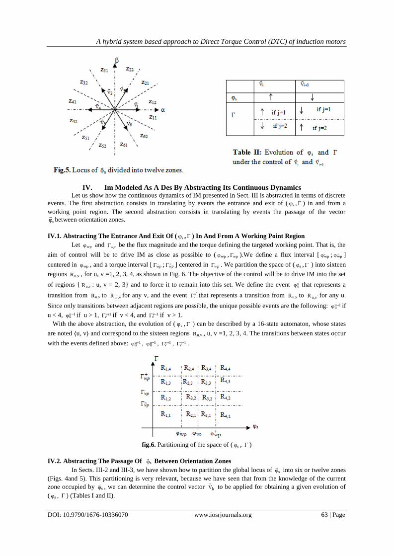
Takahashi has proposed in [5] to divide the possible global locus of sφ
into the six zones z1, z2, . . , z6 of Fig. 4.
Table I shows how the flux magnitude sφ and the torque evolve when sφ
is in zi (i = 1 · · · 6) under
the control of each of the seven vectors kV
(k = 0, i − 2 · · · i + 3), where indices i − 2 · · · i + 3 are defined
modulo 6 (from 1 to 6). Symbols , and = mean "increases", "decreases" and "is constant",
respectively. We see that under the control of 2-iV
, 1-iV
, 1iV
, 2iV
and 0V
, the evolution of sφ and is known.
But vectors iV
and 3iV
are problematic because they can both increase and decrease the torque in the same
zone zi, depending if sφ
is in the first or the second 30 degrees of zi. This problem will be called nondeterminism
of the six-zone division.
Table I: In a six zone division, evolution of sφ and when sφ is in zi (i=1,2...6) under the
control of )3,......2,0(Vk iik
III.3. Solving The Nondeterminism Of The 6-Zone Division
We propose two approaches to solve the nondeterminism of the 6-zone division. The first approach is
based on the observation that the nondeterminism occurs when sφ
is in a zone zi while one of the control vector
iV
or 3iV
is applied. A solution is to leave nondeterminism as soon as it appears, by applying a control vector
kV
different from iV
and 3iV
.We suggest to select the control vector to be applied among the four control
vectors 2-iV
, 1-iV
, 1iV
, 2iV
, because these four vectors permit to obtain all the combinations of the evolution of
( sφ , ) (see Table I).
A second approach to solve the nondeterminism is to use twelve zones by dividing each of the six
zones zi into two zones zi,1 and zi,2 comprising the first and the second 30 degrees, respectively [13], [1]. Figure
5 represents the twelve-zone division. In each zone zi,j and under the control of 2-iV
, 1-iV
, 1iV
, 2iV
and 0V
, the
evolution of sφ and is thus the one already indicated in Table I for zi. Table II shows the evolution of sφ and
in zone zi,j under the control of iV
and 3iV
.
iV
3iV
70 VorV
sφ =
? ?
2iV
1iV
1iV
2iV
sφ
A hybrid system based approach to Direct Torque Control (DTC) of induction motors
DOI: 10.9790/1676-10336070 www.iosrjournals.org 63 | Page
IV. Im Modeled As A Des By Abstracting Its Continuous Dynamics Let us show how the continuous dynamics of IM presented in Sect. III is abstracted in terms of discrete
events. The first abstraction consists in translating by events the entrance and exit of ( sφ , ) in and from a
working point region. The second abstraction consists in translating by events the passage of the vector
sφ
between orientation zones.
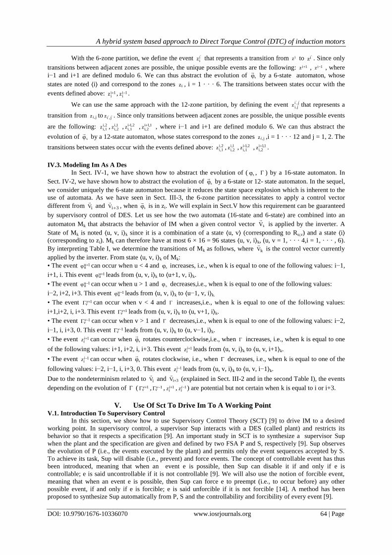
IV.1. Abstracting The Entrance And Exit Of ( sφ , ) In And From A Working Point Region
Let wpφ and wp be the flux magnitude and the torque defining the targeted working point. That is, the
aim of control will be to drive IM as close as possible to ( wpφ , wp ).We define a flux interval [ -wpφ ;
wpφ ]
centered in wpφ , and a torque interval [ wp ; wp ] centered in wp . We partition the space of ( sφ , ) into sixteen
regions vu,R , for u, v =1, 2, 3, 4, as shown in Fig. 6. The objective of the control will be to drive IM into the set
of regions { vu,R : u, v = 2, 3} and to force it to remain into this set. We define the event 'uuφ that represents a
transition from vu,R to v,u 'R for any v, and the event 'vv that represents a transition from vu,R to 'vu,R for any u.
Since only transitions between adjacent regions are possible, the unique possible events are the following: 1uuφ if
u < 4, 1uuφ if u > 1, 1v
v if v < 4, and 1vv if v > 1.
With the above abstraction, the evolution of ( sφ , ) can be described by a 16-state automaton, whose states
are noted ⟨u, v⟩ and correspond to the sixteen regions vu,R , u, v =1, 2, 3, 4. The transitions between states occur
with the events defined above: 1uuφ , 1u
uφ , 1v
v , 1vv .
fig.6. Partitioning of the space of ( sφ , )
IV.2. Abstracting The Passage Of sφ
Between Orientation Zones
In Sects. III-2 and III-3, we have shown how to partition the global locus of sφ
into six or twelve zones
(Figs. 4and 5). This partitioning is very relevant, because we have seen that from the knowledge of the current
zone occupied by sφ
, we can determine the control vector kV
to be applied for obtaining a given evolution of
( sφ , ) (Tables I and II).
A hybrid system based approach to Direct Torque Control (DTC) of induction motors
DOI: 10.9790/1676-10336070 www.iosrjournals.org 64 | Page
With the 6-zone partition, we define the event 'iiz that represents a transition from iz to 'iz . Since only
transitions between adjacent zones are possible, the unique possible events are the following: 1iz , 1iz , where
i−1 and i+1 are defined modulo 6. We can thus abstract the evolution of sφ
by a 6-state automaton, whose
states are noted ⟨i⟩ and correspond to the zones iz , i = 1 · · · 6. The transitions between states occur with the
events defined above: 1iiz , 1i
iz .
We can use the same approach with the 12-zone partition, by defining the event '' j,i
ji,z that represents a
transition from j,z i to '' j,zi . Since only transitions between adjacent zones are possible, the unique possible events
are the following: 2,ii,1z , 1,i
i,2z , 2,1-ii,1z , 1,1i
i,2z , where i−1 and i+1 are defined modulo 6. We can thus abstract the
evolution of sφ
by a 12-state automaton, whose states correspond to the zones j,z i ,i = 1 · · · 12 and j = 1, 2. The
transitions between states occur with the events defined above: 2,ii,1z , 1,i
i,2z , 2,1-ii,1z , 1,1i
i,2z .
IV.3. Modeling Im As A Des
In Sect. IV-1, we have shown how to abstract the evolution of ( sφ , ) by a 16-state automaton. In
Sect. IV-2, we have shown how to abstract the evolution of sφ
by a 6-state or 12- state automaton. In the sequel,
we consider uniquely the 6-state automaton because it reduces the state space explosion which is inherent to the
use of automata. As we have seen in Sect. III-3, the 6-zone partition necessitates to apply a control vector
different from iV
and 3iV
, when sφ
is in zi. We will explain in Sect.V how this requirement can be guaranteed
by supervisory control of DES. Let us see how the two automata (16-state and 6-state) are combined into an
automaton Mk that abstracts the behavior of IM when a given control vector kV
is applied by the inverter. A
State of Mk is noted ⟨u, v, i⟩k since it is a combination of a state ⟨u, v⟩ (corresponding to Ru,v) and a state ⟨i⟩ (corresponding to zi). Mk can therefore have at most 6 × 16 = 96 states ⟨u, v, i⟩k, (u, v = 1, · · · 4,i = 1, · · · , 6).
By interpreting Table I, we determine the transitions of Mk as follows, where kV
is the control vector currently
applied by the inverter. From state ⟨u, v, i⟩k of Mk:
• The event 1uuφ can occur when u < 4 and sφ increases, i.e., when k is equal to one of the following values: i−1,
i+1, i. This event 1uuφ leads from ⟨u, v, i⟩k to ⟨u+1, v, i⟩k.
• The event 1uuφ can occur when u > 1 and sφ decreases,i.e., when k is equal to one of the following values:
i−2, i+2, i+3. This event 1uuφ leads from ⟨u, v, i⟩k to ⟨u−1, v, i⟩k.
• The event 1vv can occur when v < 4 and increases,i.e., when k is equal to one of the following values:
i+1,i+2, i, i+3. This event 1vv leads from ⟨u, v, i⟩k to ⟨u, v+1, i⟩k.
• The event 1vv can occur when v > 1 and decreases,i.e., when k is equal to one of the following values: i−2,
i−1, i, i+3, 0. This event 1vv leads from ⟨u, v, i⟩k to ⟨u, v−1, i⟩k.
• The event 1iiz can occur when sφ
rotates counterclockwise,i.e., when increases, i.e., when k is equal to one
of the following values: i+1, i+2, i, i+3. This event 1iiz leads from ⟨u, v, i⟩k to ⟨u, v, i+1⟩k.
• The event 1iiz can occur when sφ
rotates clockwise, i.e., when decreases, i.e., when k is equal to one of the
following values: i−2, i−1, i, i+3, 0. This event 1iiz leads from ⟨u, v, i⟩k to ⟨u, v, i−1⟩k.
Due to the nondeterminism related to iV
and 3iV
(explained in Sect. III-2 and in the second Table I), the events
depending on the evolution of ( 1vv , 1v
v , 1iiz , 1i
iz ) are potential but not certain when k is equal to i or i+3.
V. Use Of Sct To Drive Im To A Working Point V.1. Introduction To Supervisory Control
In this section, we show how to use Supervisory Control Theory (SCT) [9] to drive IM to a desired
working point. In supervisory control, a supervisor Sup interacts with a DES (called plant) and restricts its
behavior so that it respects a specification [9]. An important study in SCT is to synthesize a supervisor Sup
when the plant and the specification are given and defined by two FSA P and S, respectively [9]. Sup observes
the evolution of P (i.e., the events executed by the plant) and permits only the event sequences accepted by S.
To achieve its task, Sup will disable (i.e., prevent) and force events. The concept of controllable event has thus
been introduced, meaning that when an event e is possible, then Sup can disable it if and only if e is
controllable; e is said uncontrollable if it is not controllable [9]. We will also use the notion of forcible event,
meaning that when an event e is possible, then Sup can force e to preempt (i.e., to occur before) any other
possible event, if and only if e is forcible; e is said unforcible if it is not forcible [14]. A method has been
proposed to synthesize Sup automatically from P, S and the controllability and forcibility of every event [9].
A hybrid system based approach to Direct Torque Control (DTC) of induction motors
DOI: 10.9790/1676-10336070 www.iosrjournals.org 65 | Page
V.2. The Plant Inv-Im Modeled As A Des
The plant to be controlled is the system Inv-IM (i.e.,inverter with IM). In Section II, we have modeled
the inverter by an automaton A with 7 states qk (k = 0, · · · 6) corresponding to the 7 control vectors kV
,
respectively. And in Section IV-3, when a given kV
is applied by the inverter to the IM, we have modeled the
evolution of IM by an automaton Mk that can have at most 6 × 16 = 96 states ⟨u, v, i⟩ k, (u, v = 1, ....4, i = 1,....,
6). Therefore, the system Inv-IM can be modeled by replacing in A each mode qk by the automaton Mk. The
transition from any state ⟨u, v, i⟩⋆ to a state ⟨u, v, i⟩k occurs by an event Vk. The obtained automaton, noted P,
can therefore have at most 7 × 96 = 672 states. The initial state is ⟨1; 1; 1⟩0, that is, initially: the flux and the
torque are in Region R1,1, the flux vector is in zone z1 and the null control vector 0V
is applied. The set of
marked states is {⟨u; v; i⟩k : u, v = 2, 3}, because the objective of the control is to drive Inv-IM into the set of
regions {Ru,v : u, v = 2, 3} (i.e., the set of states {⟨u; v; i⟩k : u, v = 2, 3}), and then to force it to remain into this
set. For the purpose of control, we define an undesirable event Null meaning that the flux or the torque has
decreased to zero, and a state E reached with the occurrence of Null . We will see later how Null and E are
necessary. Therefore, the automaton P has actually at most 673 (672 + the state E), and its alphabet is:
null1.....6k:V1,......6i:Z,Z
2,3,4vu,:Γ,φ1,2,3vu,:Γ,φ
k1i
i1i
i
1vv
1uu
1vv
1uu
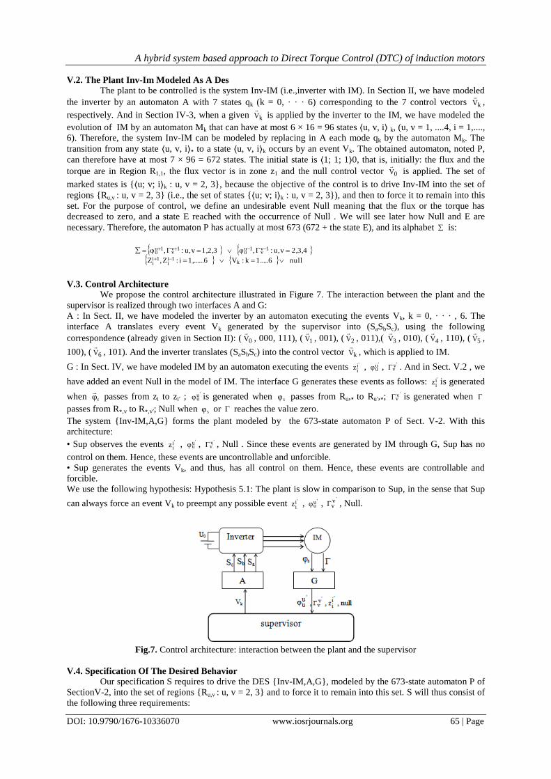
V.3. Control Architecture
We propose the control architecture illustrated in Figure 7. The interaction between the plant and the
supervisor is realized through two interfaces A and G:
A : In Sect. II, we have modeled the inverter by an automaton executing the events Vk, k = 0, · · · , 6. The
interface A translates every event Vk generated by the supervisor into (SaSbSc), using the following
correspondence (already given in Section II): ( 0V
, 000, 111), ( 1V
, 001), ( 2V
, 011),( 3V
, 010), ( 4V
, 110), ( 5V
,
100), ( 6V
, 101). And the inverter translates (SaSbSc) into the control vector kV
, which is applied to IM.
G : In Sect. IV, we have modeled IM by an automaton executing the events 'iiz , 'u
uφ , 'vv . And in Sect. V.2 , we
have added an event Null in the model of IM. The interface G generates these events as follows: 'iiz is generated
when sφ
passes from zi to zi′ ; 'uuφ is generated when sφ passes from Ru,⋆ to Ru′,⋆;
'vv is generated when
passes from R⋆,v to R⋆,v′; Null when sφ or reaches the value zero.
The system {Inv-IM,A,G} forms the plant modeled by the 673-state automaton P of Sect. V-2. With this
architecture:
• Sup observes the events 'iiz , 'u
uφ , 'vv , Null . Since these events are generated by IM through G, Sup has no
control on them. Hence, these events are uncontrollable and unforcible.
• Sup generates the events Vk, and thus, has all control on them. Hence, these events are controllable and
forcible.
We use the following hypothesis: Hypothesis 5.1: The plant is slow in comparison to Sup, in the sense that Sup
can always force an event Vk to preempt any possible event 'iiz , 'u
uφ , 'v
v , Null.
Fig.7. Control architecture: interaction between the plant and the supervisor
V.4. Specification Of The Desired Behavior
Our specification S requires to drive the DES {Inv-IM,A,G}, modeled by the 673-state automaton P of
SectionV-2, into the set of regions {Ru,v : u, v = 2, 3} and to force it to remain into this set. S will thus consist of
the following three requirements:
A hybrid system based approach to Direct Torque Control (DTC) of induction motors
DOI: 10.9790/1676-10336070 www.iosrjournals.org 66 | Page
1) P, which is initially in the region R1,1, must enter the set of regions {Ru,v : u, v = 2, 3}, i.e., the set
of states {⟨u; v; i⟩k : u, v = 2, 3}. Or equivalently: the plant must leave the set of regions {Ru,v : (u = 1)
∨ (v =1)}, i.e., the set of states {⟨u; v; i⟩k : (u = 1) ∨ (v =1)}. This requirement is guaranteed by the
following one: the event Null must never occur. Indeed, Null can occur only from a region in
{Ru,v : (u = 1)∨ (v =1)}, and can be avoided uniquely by driving IM to leave the set of regions
{Ru,v : (u = 1) ∨ (v = 1)}. In fact, the event Null has been introduced as a mean to express this first
requirement.
2) After the plant enters a region R2,v or R3,v, then it never goes to a region R1,v or R4,v. Or equivalently:
the events 12φ and 4
3φ must never occur.
3) After the plant enters a region Ru,2 or Ru,3, then it never goes to a region Ru,1 or Ru,4. Or
equivalently:the events 12 and 4
3 must never occur.
To recapitulate, S simply forbids the following five (uncontrollable and unforcible) events Null , 12φ , 4
3φ ,
12 , 4
3 . S can be expressed as a single-state automaton with self loops of all the events of the alphabet
except the above five events. If we apply a synchronized product of P and S, we have the specification S′
obtained from P by “cutting” the above five events.
V.5. Supervisor Synthesis
The inputs of the supervisor synthesis are:
• Automaton P modeling the plant (Sect. V-2).
• Automaton S modeling the specification (Sect. V-4).
• Controllability and forcibility of each event.
We have justified in Section V-3 that : the events 'iiz , 'u
uφ , 'vv , Null are uncontrollable and unforcible; and the
events Vk are controllable and forcible. We have applied the synthesis procedure of the software tool TTCT
[15]. With TTCT, forcible events can be forced to occur before an event tick that models the passing of one time
unit. To be able to use TTCT, we have adapted P and S by preceding every unforcible event by the event tick.
This adaptation is consistent with Hypothesis 5.1 in Section V-3. The solution synthesized provides several
possible scenarios of control. Here is the simplest one:
• Initially, we are in the initial state ⟨1; 1; 1⟩0, that is: the flux and the torque are in Region R1,1, the flux vector is
in zone z1, and the null control vector 0V
is applied.
• When a state ⟨u; v; i⟩k such that u < 3 and v < 3 is reached and k ≠ i+1, then Sup generates the event 1iV
.
Intuitively, when sφ < wpφ and < wp , the control vector 1iV
is applied to increase sφ and . Note that this
case applies to the initial state.
• When a state ⟨3; v; i⟩k such that v < 3 is reached and k ≠ i+2, then Sup generates the event 2iV
. Intuitively,
when sφ > wpφ and < wp , the control vector 2iV
is applied to decrease sφ and increase .
• When a state ⟨u; 3; i⟩k such that u < 3 is reached and k ≠ i−1, then Sup generates the event 1iV
. Intuitively,
when sφ < wpφ and > wp , the control vector 1iV
is applied to increase sφ and decrease .
• When a state ⟨3; 3; i⟩k is reached and k ≠ i−2, then Sup generates the event 2iV
. Intuitively, when
sφ > wpφ and > wp , the control vector 2iV
is applied todecrease sφ and .
Note that Sup never generates an event kV
that leads to a nondeterministic state ⟨u; v; i⟩k, i.e., such that k = i or
k = i+3. Nevertheless, a nondeterministic state can be reached by an event i1-iz or i
1iz . When such a situation
occurs, Sup has not a real control on , because it is not known whether increases or decreases. Sup will quit
such a nondeterministic situation by generating one of the four control vectors 2iV
, 1iV
, 1iV
, 2iV
, depending
on whether each of sφ and must be increased or decreased.
VI. Simulations Results
VI.1. Conditions Of Simulation
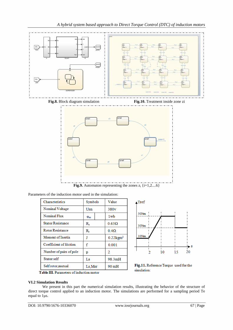
The simulation is performed in simulation environement MATLAB/SIMULINK/STATEFLOW
(2014b). In figure 8, we present the control architecture which consits of the interaction between the plant and
the supervisor through two interfaces A and G. The controler recieves in its inputs the events generated by
interface G and apply a command to the plant via the interface A.
A hybrid system based approach to Direct Torque Control (DTC) of induction motors
DOI: 10.9790/1676-10336070 www.iosrjournals.org 67 | Page
Fig.8. Block diagram simulation Fig.10. Treatment inside zone zi
Fig.9. Automaton representing the zones zi {i=1,2....6}
Parameters of the induction motor used in the simulation:
VI.2 Simulation Results
We present in this part the numerical simulation results, illustrating the behavior of the structure of
direct torque control applied to an induction motor. The simulations are performed for a sampling period Te
equal to 1μs.
A hybrid system based approach to Direct Torque Control (DTC) of induction motors
DOI: 10.9790/1676-10336070 www.iosrjournals.org 68 | Page
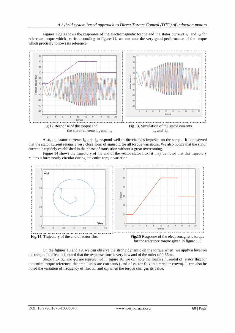
Figures 12,13 shows the responses of the electromagnetic torque and the stator currents isα and isβ for
reference torque which varies according to figure 11, we can note the very good performance of the torque
which precisely follows its reference.
Fig.12.Response of the torque and Fig.13. Simulation of the stator currents
the stator currents isα and isβ isα and isβ
Also, the stator currents isα and isβ respond well to the changes imposed on the torque. It is observed
that the stator current retains a very close form of sinusoid for all torque variations. We also notice that the stator
current is rapidely established in the phase of transistion without a great overcoming.
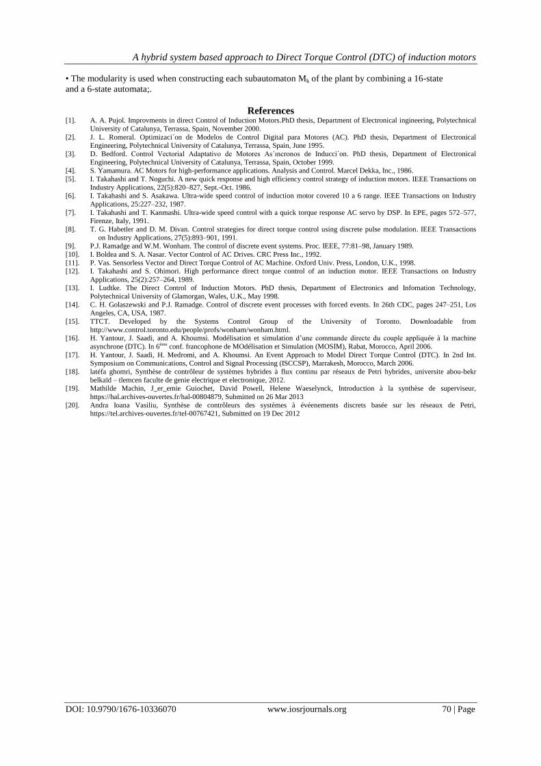
Figure 14 shows the trajectory of the end of the vector stator flux, it may be noted that this trajectory
retains a form nearly circular during the entire torque variation.
Fig.14. Trajectory of the end of stator flux Fig.15 Response of the electromagnetic torque
for the reference torque given in figure 11.
On the figures 15 and 19, we can observe the strong dynamic on the torque when we apply a level on
the torque. In effect it is noted that the response time is very low and of the order of 0.35ms.
Stator flux φsα and φsβ are represented in figure 16, we can note the forms sinusoidal of stator flux for
the entire torque reference, the amplitudes are constants ( end of vector flux in a circular crown). It can also be
noted the variation of frequency of flux φsα and φsβ when the torque changes its value.
ϕsα
ϕsβ

A hybrid system based approach to Direct Torque Control (DTC) of induction motors
DOI: 10.9790/1676-10336070 www.iosrjournals.org 69 | Page
Fig.16 Response of the stator flux φsα and φsβ Fig.17. Simulation of the voltage Vsα and Vsβ
Fig.18. Torque variation around the reference Tref=30Nm Fig.19. Response time of the torque
VII. Conclusion In this paper, we have studied the Direct Torque Control (DTC) of an Induction Motor coupled to an
Inverter (Inv-IM). DTC permits to control directly the stator flux and the torque by selecting the appropriate
inverter state. Our first contribution is the modeling of Inv-IM as a hybrid system (HS), where the inverter is
modeled as a discrete event system (DES) and the induction motor is modeled as a continuous system. Our
second contribution is the abstraction of the continuous dynamics of the induction motor as a DES. The HS is
thus modeled as a DES. The advantage of this abstraction is that all the rigorous analysis and design methods for
DES can be applied for studying DTC. Our third contribution is the use of Supervisory Control Theory (SCT)
of DES to drive Inv-IM to a desired working point.
For the sake of clarity, we have based all our study on the fact that the targeted working point is an
interval of stator flux and an interval of torque. But our study can be easily adapted for other working points, for
example moving the head of the stator flux vector in a circular ring.
An interesting previous work has been done in [16], [17], but the specification was defined with an a
priori knowledge of the solution and was not defined as the most permissive solution. Besides, no solution was
proposed to the nondeterminism of the 6-zone division. In the present paper, these limitations are solved by
taking more advantage of SCT.
As a future work, we intend to improve our control method by using a hierarchical control and a
modular control, which are very suitable to take advantage of the fact that the eventbased model of the plant has
been constructed hierarchically and modularly. Indeed:
• The hierarchy is in two levels in the construction of the plant. In a first level, the inverter is modeled by an
7-state automaton A, whose states qk correspond to the application of the control vectors 1....6k:Vk
. In a
second level, each state qk is replaced by an automaton Mk modeling the behavior of the induction motor under
the control of kV
.
temps
Vsα, Vsβ
Vsβ
A hybrid system based approach to Direct Torque Control (DTC) of induction motors
DOI: 10.9790/1676-10336070 www.iosrjournals.org 70 | Page
• The modularity is used when constructing each subautomaton Mk of the plant by combining a 16-state
and a 6-state automata;.
References [1]. A. A. Pujol. Improvments in direct Control of Induction Motors.PhD thesis, Department of Electronical ingineering, Polytechnical
University of Catalunya, Terrassa, Spain, November 2000.
[2]. J. L. Romeral. Optimizaci´on de Modelos de Control Digital para Motores (AC). PhD thesis, Department of Electronical Engineering, Polytechnical University of Catalunya, Terrassa, Spain, June 1995.
[3]. D. Bedford. Control Vectorial Adaptativo de Motores As´ıncronos de Inducci´on. PhD thesis, Department of Electronical
Engineering, Polytechnical University of Catalunya, Terrassa, Spain, October 1999. [4]. S. Yamamura. AC Motors for high-performance applications. Analysis and Control. Marcel Dekka, Inc., 1986.
[5]. I. Takahashi and T. Noguchi. A new quick response and high efficiency control strategy of induction motors. IEEE Transactions on
Industry Applications, 22(5):820–827, Sept.-Oct. 1986. [6]. I. Takahashi and S. Asakawa. Ultra-wide speed control of induction motor covered 10 a 6 range. IEEE Transactions on Industry
Applications, 25:227–232, 1987.
[7]. I. Takahashi and T. Kanmashi. Ultra-wide speed control with a quick torque response AC servo by DSP. In EPE, pages 572–577, Firenze, Italy, 1991.
[8]. T. G. Habetler and D. M. Divan. Control strategies for direct torque control using discrete pulse modulation. IEEE Transactions
on Industry Applications, 27(5):893–901, 1991. [9]. P.J. Ramadge and W.M. Wonham. The control of discrete event systems. Proc. IEEE, 77:81–98, January 1989.
[10]. I. Boldea and S. A. Nasar. Vector Control of AC Drives. CRC Press Inc., 1992.
[11]. P. Vas. Sensorless Vector and Direct Torque Control of AC Machine. Oxford Univ. Press, London, U.K., 1998. [12]. I. Takahashi and S. Ohimori. High performance direct torque control of an induction motor. IEEE Transactions on Industry
Applications, 25(2):257–264, 1989. [13]. I. Ludtke. The Direct Control of Induction Motors. PhD thesis, Department of Electronics and Infomation Technology,
Polytechnical University of Glamorgan, Wales, U.K., May 1998.
[14]. C. H. Golaszewski and P.J. Ramadge. Control of discrete event processes with forced events. In 26th CDC, pages 247–251, Los Angeles, CA, USA, 1987.
[15]. TTCT. Developed by the Systems Control Group of the University of Toronto. Downloadable from
http://www.control.toronto.edu/people/profs/wonham/wonham.html. [16]. H. Yantour, J. Saadi, and A. Khoumsi. Modélisation et simulation d’une commande directe du couple appliquée à la machine
asynchrone (DTC). In 6ème conf. francophone de MOdélisation et Simulation (MOSIM), Rabat, Morocco, April 2006.
[17]. H. Yantour, J. Saadi, H. Medromi, and A. Khoumsi. An Event Approach to Model Direct Torque Control (DTC). In 2nd Int. Symposium on Communications, Control and Signal Processing (ISCCSP), Marrakesh, Morocco, March 2006.
[18]. latéfa ghomri, Synthèse de contrôleur de systèmes hybrides à flux continu par réseaux de Petri hybrides, universite abou-bekr
belkaïd – tlemcen faculte de genie electrique et electronique, 2012. [19]. Mathilde Machin, J_er_emie Guiochet, David Powell, Helene Waeselynck, Introduction à la synthèse de superviseur,
https://hal.archives-ouvertes.fr/hal-00804879, Submitted on 26 Mar 2013
[20]. Andra Ioana Vasiliu, Synthèse de contrôleurs des systèmes à évéenements discrets basée sur les réseaux de Petri, https://tel.archives-ouvertes.fr/tel-00767421, Submitted on 19 Dec 2012


![Predictive Vector Selector for Direct Torque Control of ...Direct Torque Control using Matrix Converters are shown. I. INTRODUCTION Direct Torque Control (DTC) [1] and Direct Self](https://img.pdfslide.net/doc/110x75/5f70317e3425cd0d4608358b/predictive-vector-selector-for-direct-torque-control-of-direct-torque-control.jpg)