Embed Size (px)
Citation preview

Abstract— This paper proposes a novel design methodology
to synthesize flexure-based parallel manipulators (FPM) for
high precision micro/nano-scale manipulation. Unlike
traditional synthesis methods, the proposed method uses a
structural optimization algorithm that is independent of human
intuition, to synthesize compliant joints with optimal stiffness
characteristics. This algorithm is able to evolve the topology and
shape of the compliant joints. Based on finite element analysis,
the synthesized compliant joints are able to achieve better
stiffness characteristics than the traditional compliant joints.
This allows the synthesized joints to achieve a large deflection
range while maintaining their capabilities to resist external
wrenches in the non-actuating directions. A planar motion FPM
with a workspace of 4 mm2 × 2 is formed by assembling the
optimal compliant joints. The actuating compliance of the joints
and FPM are validated by experiments and their deviation
between the experimental results and the simulation prediction
are within 10% and 18% respectively.
I. INTRODUCTION
Compliant mechanisms are structures that have high compliance in the actuating directions while maintaining high stiffness in the non-actuating directions. As these structures achieve their motions via elastic deformation, they are able to eliminate backlash and mechanical play [1]. These unique characteristics allow the compliant mechanisms to achieve highly repetitive motions, making them the ideal candidates to perform micro/nano-scale manipulations [2-4].
The elasto-kinematics method is an established method to synthesize multiple degrees-of-freedom (DOF) compliant mechanisms [5, 6]. This method classifies the components of the compliant mechanism into groups of rigid-bodies (linkages) coupled together by the elastic-bodies (compliant joints). There are two basic types of compliant joints, the notch-type and beam-type, and their deformation characteristics resemble motion achieved by traditional joints that have springs attached to them. By integrating the compliant joints with rigid-bodies, motions of the compliant mechanisms and the traditional mechanisms resemble one another [5, 6]. Based on this concept, Ryu et al. and Lee et al.
have utilized notch-type compliant joints to develop X-Y-z planar motion compliant mechanisms [7, 8]. Ryu et al. is able to achieve 8 nm translational resolution and 0.057 arcsecond rotational resolution while Lee et al. is able to achieve 10 nm
1 School of Mechanical and Aerospace Engineering, Nanyang Technological University, Singapore 639798. 2 Department of Mechanical Engineering and Robotics Institute, Carnegie
Mellon University, PA 15213. 3 Mechatronics Group, Singapore Institute of Manufacturing Technology,
Singapore 638075.
translational resolution and 0.2 arcsecond rotational resolution respectively. However, their workspace is small - ranging between hundreds of micrometers in the translational direction and hundreds of arcseconds in the rotational direction. This small workspace characteristic is due to the high actuating stiffness nature of the notch-type compliant joint. In order to increase the workspace, the notch-type compliant joints can be replaced by the more compliant beam-type compliant joints. This was demonstrated by Yang
et al. where a beam-type X-Y-z planar motion compliant mechanism which has a much larger workspace of
2.5mm×2.5mm×2.5 is developed [9]. Although the beam-type compliant mechanisms have larger workspace than their notch-type counterparts, their non-actuating stiffness are also lower. This reduces the beam-type compliant mechanisms' capability to resist external wrenches in the non-actuating directions and thus affecting its overall precision.
Despite having intensive research on the design of the notch-type and beam-type compliant joints, it should be noted that these joints are fundamentally created via human intuition. Thus, the stiffness characteristics of these compliant joints might not be optimized. This prevents the assembled compliant mechanisms from achieving their full potential of enhancing their ratio of non-actuating to actuating stiffness. A promising new compliant joint synthesis method that is not limited by human intuition was suggested by Wang [10]. By using a structural optimization algorithm, Wang was able to independently synthesize a prismatic compliant joint that resembles the linear spring design [10]. The design procedure is to first discretize the design domain into a mesh of quadrilateral finite elements. During the optimization, behavior of the compliant mechanism is determined by finite element analysis (FEA). Subsequently, based on the fitness function, the loading and boundary conditions of the design domain, the optimization algorithm will determine the final state of these elements. Ideally, all the elements should either be black (solid) or white (void) at the final state. Although this synthesis method had demonstrated great potential, the final design obtained by Wang contains ambiguous "grey" elements which have no physical meaning. Thus, it is still a challenging task to synthesize feasible compliant joints by using a structural optimization algorithm and eventually assemble them into a multi-DOF compliant mechanism.
This paper presents a novel hybrid topological and structural optimization method that is able to synthesize feasible compliant joints with optimal stiffness characteristics. The obtained compliant joints are able to achieve actuating stiffness that are in the same order as the beam-type joints but with higher non-actuating stiffness. The synthesized compliant joints are eventually assembled to form a 3-DOF
A Hybrid Topological and Structural Optimization Method to
Design a 3-DOF Planar Motion Compliant Mechanism
Guo Zhan Lum1,2,3
, Student Member; IEEE, Tat Joo Teo3, Member; IEEE, Guilin Yang
3, Member;
IEEE, Song Huat Yeo1 and Metin Sitti
2, Senior Member; IEEE
2013 IEEE/ASME International Conference onAdvanced Intelligent Mechatronics (AIM)Wollongong, Australia, July 9-12, 2013
978-1-4673-5320-5/13/$31.00 ©2013 IEEE 247

planar motion flexure-based parallel manipulator (FPM). The organization of the paper is as follows: the kinematics configuration of the proposed FPM is described in Section II. Sections III and IV will discuss about the development of the compliant joints and their assembly into the FPM respectively. The experimental results of the compliant joints and FPM prototype are shown in Section V. Lastly, the conclusion is provided in Section VI.
II. PROPOSED 3PPR FPM
The proposed 3-DOF compliant mechanism is articulated
by a parallel kinematics configuration. In order to realize a
X-Y-z planar motion compliant mechanism, there are three
possible combinations, 3-legged Revolute-Revolute-
Revolute (3RRR), 3-legged Prismatic-Revolute-Revolute
(3PRR), and the 3-legged Prismatic-Prismatic-Revolute
(3PPR) [9]. Here, the 3-legged prismatic-prismatic-revolute
3PPR is selected over the 3PRR and 3RRR because
compliant prismatic joints are generally stiffer and more
deterministic than the compliant revolute joints. The 3PPR
schematic is shown in Fig. 1 where the end-effector (centre
of the moving platform) is connected to the fixed base by
three identical parallel kinematics chains. Each chain
comprises of a serially-connected active prismatic joint (P)
and a passive prismatic-revolute (PR) joint.
Fig. 1. Schematic drawings of the 3PPR at home pose.
A global frame, {g}, is fixed at the center of the mechanism when it is at the home pose. Each kinematic chain
is assigned a corresponding local frame, {i}, {i +, 1 ≤ i ≤
3}, and their origins are fixed at the home position of their P joint. The orientation of the frames {1}, {2} and {3} have a
relative z-axis rotation angle of [1 2 3] =
]
from the global frame respectively. The superscripts of the vectors or matrices indicate the frame used to describe them. For example, a vector
{g}r means that this vector is viewed in
the global frame. These frame conventions will be used for the analyses in Section IV.
III. SYNTHESIZING COMPLIANT JOINTS WITH OPTIMAL
STIFFNESS CHARACTERISTICS
In order to synthesize a compliant mechanism which has
identical kinematic requirements as the 3PPR parallel
manipulator, the utilized conventional joints are converted to
corresponding compliant joints. Two compliant joints – P
and PR joints will be synthesized via the hybrid topology and
structural optimization.
A. The Hybrid Topological and Structural Optimization
Algorithm
There are various types of structural optimization algorithms in literature such as the SIMP [11], morphological representation [12], homogenous methods [13] and the mechanism approach [14]. In this paper, the mechanism approach is the selected algorithm to synthesize the compliant joints. This algorithm uses traditional mechanisms as seeds to represent the topology and shape of the compliant joints. A notable advantage for this algorithm is that it is able to eliminate infeasible solutions such as disconnected solid elements and ambiguous “gray” elements while exhibiting good convergence capability.
In order to implement the mechanism approach, an appropriate traditional mechanism that has the same DOF requirement as the compliant joint is selected as the seed. The seed selection can be achieved by using the well-established classical mechanism synthesis methods as a guideline. This seed will then be superimposed onto a design domain where all its finite elements are initially void. The pose of the seed can be varied by changing the link lengths and their orientations. Each link of the seed is represented by one cubic curve, one harmonic curve, and their reflected curves about the link. This is illustrated in Fig. 2 using the four-bar linkage as the seed. The four curves form the boundaries used in the selection of solid elements. Based on the value of m assigned to each link ( ), different combinations of solid elements can be generated. If m = 1, all the elements bounded between the original curves and the link are solid. When m = 2, all the elements bounded by the reflected curves and the link are solid. When m = 3, the solid elements will be the combined elements of the first two cases.
Fig. 2. Curves generated by the last link of the seed.
A corresponding structure is produced when all the links
follow the above-mentioned description as shown in Fig. 3.
By varying the design parameters such as the seed’s pose and
the curve parameters, different structures are generated.
Although the mechanism approach uses a seeding method,
the topologies are not limited by its seed. The seed’s
topology can be changed if any link’s length approaches zero
during the optimization. The fixed points and the coupler
point of the seed correspond to the fixed points and loading
points of the compliant joints. Note that there is only one
loading point for compliant joints.
Original
Reflected
x1
Cubic curves
Harmonic curves
y1 m = 1
m = 2
m = 3
Seed
Design Domain
{g}
x1 y1
x2
y2
x3
y3
Moving
platform
P
P
P
PR
PR
PR
248
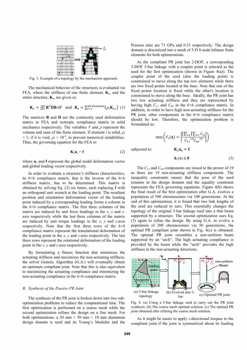
Fig. 3. Example of a topology by the mechanism approach.
The mechanical behavior of the structures is evaluated via
FEA, where the stiffness of one finite element, Ke, and the
entire structure, Ks, are given as:
∭ ∑ ( ) (1)
The matrices B and D are the commonly used deformation
matrix in FEA and isotropic compliance matrix in solid
mechanics respectively. The variables V and represent the
volume and state of the finite element. If element i is solid, i
= 1; if it is void, i = 10-6
, to prevent numerical instabilities.
Thus, the governing equation for the FEA is:
Ksus = f (2)
where us and f represent the global nodal deformation vector
and global loading vector respectively.
In order to evaluate a structure’s stiffness characteristics,
its 6×6 compliance matrix, that is the inverse of the 6×6
stiffness matrix, has to be determined. This matrix is
obtained by solving Eq. (2) six times, each replacing f with
an orthogonal unit wrench at the loading point. The resultant
position and orientation deformation vector of the loading
point induced by a corresponding loading forms a column in
the 6×6 compliance matrix. The first three columns of the
matrix are induced by unit force loadings in the x, y and z-
axis respectively while the last three columns of the matrix
are induced by unit torque loadings in the x, y and z-axis
respectively. Note that the first three rows of the 6×6
compliance matrix represent the translational deformation of
the loading point in the x, y and z-axis respectively. The last
three rows represent the rotational deformation of the loading
point in the x, y and z-axis respectively.
By formulating a fitness function that minimizes the
actuating stiffness and maximizes the non-actuating stiffness,
the solver Genetic Algorithm (G.A.) will eventually obtain
an optimum compliant joint. Note that this is also equivalent
to maximizing the actuating compliance and minimizing the
non-actuating compliance in the 6×6 compliance matrix.
B. Synthesis of the Passive PR Joint
The synthesis of the PR joint is broken down into two sub-
optimization problems to reduce the computational time. The
first optimization is performed on a coarse mesh while the
second optimization refines the design on a fine mesh. For
both optimizations, a 20 mm × 50 mm × 10 mm aluminum
design domain is used and its Young’s Modulus and the
Poisson ratio are 71 GPa and 0.33 respectively. The design
domain is discretized into a mesh of 3-D 8-node bilinear finite
elements for both optimizations.
As the compliant PR joint has 2-DOF, a corresponding
2-DOF 5-bar linkage with a coupler point is selected as the
seed for the first optimization (shown in Figure 4(a)). The
coupler point of the seed (also the loading point) is
constrained to move along the top row elements while there
are two fixed points located at the base. Note that one of the
fixed points location is fixed while the other's location is
constrained to move along the base. Ideally, the PR joint has
two low actuating stiffness and they are represented by
having high C11 and C66 in the 6×6 compliance matrix. In
addition, in order to have high non-actuating stiffness for the
PR joint, other components in the 6×6 compliance matrix
should be low. Therefore, the optimization problem is
formulated as:
( ( ) |∏ ∏
|)
subjected to:
h1(x) ≤ 0 (3)
The C11 and C66 components are raised to the power of 19
as there are 19 non-actuating stiffness components. The
inequality constraints ensure that the pose of the seed
remains in the design domain and the equality constraint
represents the FEA governing equations. Figure 4(b) shows
the final result of the first optimization after G.A. evolves a
population of 500 chromosomes via 100 generations. At the
end of this optimization, it is found that two link lengths of
the seed are reduced to zero. This essentially changes the
topology of the original 5-bar linkage seed into a thin beam
supported by a structure. The second optimization uses Eq.
(3) again to refine the design. By using G.A. to evolve a
population of 200 chromosomes via 50 generations, the
optimal PR compliant joint shown in Fig. 4(c) is obtained.
The optimal PR joint resembles a non-uniform beam
supported by an “arch”. The high actuating compliance is
provided by the beam while the “arch” provides the high
stiffness in the non-actuating directions.
Fig. 4. (a) Using a 5-bar linkage seed to carry out the PR joint
synthesis. (b) The coarse mesh optimal solution. (c) The optimal PR
joint obtained after refining the coarse mesh solution.
As it might be easier to apply z-directional torques to the
compliant joint if the joint is symmetrical about its loading
fx
non-uniform Beam
x
y
Arch Supports
loading point
fx mz fx
mz
(a) 5-bar linkage
topology (b) Evolved into 3-
bar (c) Optimal PR joint
249

point, the finalized PR joint (Fig. 5(a)) is obtained by
reflecting the obtained structure about its loading point. The
6×6 stiffness matrix of the finalized design, KPR, is shown in
Eq. (4) and it is compared to the stiffness matrix of the
traditional beam-type design, KEK1 in Eq. (5). If any
components in KPR and KEK1 are smaller than 10-2
, a zero is
assigned to them as they are relatively insignificant. Note
that the traditional beam-type design is a thin beam that is
fixed on both ends (Fig. 5(b)). As it might be easier to
compare if both designs have at least one identical actuating
compliance, the beam thickness of the traditional design is
adjusted to 0.56 mm to match the rotary actuating stiffness,
K66, of the finalized PR joint design.
[
]
(4)
[
]
(5)
A matrix Ra is used to compare KPR and KEK1. Each
component in Ra, R
aij, represents the ratio of KPR,ij against
KEK1,ij if neither are zero. A zero will be assigned to Raij if
both KPR,ij and KEK1,ij are zero.
[
]
(6)
In order for the finalized PR joint to exhibit lower actuating stiffness and higher non-actuating stiffness, R
a11 and
Ra66 should be less than 1 while other non-zero R
aij should be
more than 1. Based on Eq. (6), the final design has a lower translational actuating stiffness than the traditional design as R
a11 is less than 1. Furthermore, except for R
a33, the finalized
PR joint has higher non-actuating stiffness than the traditional design too. This is especially true for the R
a55 and R
a42 where
the finalized design is more than 2 and 1.5 times stiffer than the traditional design respectively. Note that out of the seven non-zero stiffness components, five components have improved. Since the finalized PR joint is shown to have lower actuating stiffness and higher non-actuating stiffness, it can be concluded that the finalized PR joint design is better.
Fig. 5. (a) The finalized PR joint design that is obtained by reflecting Fig. 4(c) about its loading point. (b) The traditional PR joint design.
C. Synthesis of the Active P Joint
Similar to the synthesis of the PR joint, the P joint
synthesis is split into two optimization problems so as to
reduce computational time. The first optimization uses a
coarse mesh while the second optimization refines the design
with a fine mesh. For both optimizations, the design domain
is a 25 mm × 50 mm × 10 mm aluminum metal plate and its
Young’s Modulus and Poisson ratio are 71 GPa and 0.3
respectively. The design domain is discretized into a mesh of
identical 3-D 8-node bilinear finite elements.
Similar to a linear guide, the ideal characteristic of a
compliant P joint is that it has low stiffness in one actuating
translational direction and high stiffness for other non-
actuating directions. This infers that the P-joint is a 1-DOF
compliant joint and thus a simple 4-bar linkage with a coupler
point is selected as the seed for the first optimization. The
seed’s coupler point (loading point) is located at the top row's
central element. There are two fixed points and they are
located at the extreme ends of the bottom row. Note that the
pose of the seed used in the first optimization is random (as
shown in figure 6(a)) and it can be evolved.
The actuating stiffness is represented by the C11
component in the C6×6. In order to minimize this stiffness and
maximize the non-actuating stiffness, C11 and other
components in C6×6 have to be maximized and minimized
respectively. As C6×6 is a symmetry matrix, the optimization
problem is:
( ( ) |∏ ∏
|)
subjected to:
h2(x) ≤ 0 (7)
The C11 component is raised to the power of 20 as there
are 20 non-actuating stiffness components. The vector x
represents the design variables while the equality constraints
represent the FEA governing equation. The inequality
constraints are used to ensure that the seed's pose remains in
the design domain. The first optimization is carried out by
evolving a population of 400 chromosomes via 100
generations of evolution and Fig. 6(b) shows the final result.
Although the topology of the optimal seed remains as a four-
bar linkage after the first optimization, the optimal pose has
been determined. The links of the seed are placed either
vertically or horizontally (see the outlined yellow lines in Fig.
6(b)). The second optimization refines this design with a fine
mesh by using Eq. (7) and the optimal seed pose shown in
Fig. 6(b). The optimal P joint is obtained after G.A. evolves a
random initial population of 200 chromosomes via 50
generations and it is shown in figure 6(c).
The optimal P joint resembles a tapered-shape rigid-link
supported by two thin beams. A comparison between the
optimal P joint and the traditional beam-type linear-spring
design is made in Fig. 7. The 6×6 stiffness matrix for the
optimal P joint, KP, and the traditional beam-type design,
KEK2, are shown in Eq. (8) and (9) respectively. Note that any
x
y
fx
mz
a) Finalized PR joint design
fx
mz
b) Traditional design
10 mm
2 mm 0.4 mm
0.56 mm
250

components in KP and KEK2 that are smaller than 10-2
are
assigned with a zero because they are relatively insignificant.
Fig. 6. (a) Using a 4-bar linkage seed to carry out the P joint
synthesis. (b) The coarse mesh optimal solution. (c) The optimal P
joint obtained after refining the coarse mesh solution.
Fig. 7. (a) The traditional linear spring P joint. (b) The obtained
optimal P joint
[
]
(8)
[
]
(9)
A matrix Rb is used to compare KP and KEK2. Each
component in Rb, R
bij, represents the ratio of KP,ij against
KEK2,ij if neither are zero. A zero will be assigned to Rbij if
both KP,ij and KEK2,ij are zero.
[
]
(10)
In order for the optimal P joint to exhibit lower actuating
stiffness and higher non-actuating, Rb11 should be less than 1
while other non-zero components should be more than 1. As
all the non-zero components in Rb are either more than or
equal to 1, this means that the overall stiffness for the
optimal P joint is higher than the traditional design. Thus,
this also implies that the optimal P joint has higher non-
actuating stiffness too. This is especially true for the Rb
32 and
Rb22 where the optimal topology design is about 14% and 9%
stiffer respectively. Since both the designs have identical
actuating stiffness (Rb11 = 1), it can be concluded that the
optimal P joint has a better overall stiffness characteristics.
The optimal P joint is able to exhibit higher non-actuating
stiffness because its tapered-shape rigid link has more layers
of finite elements. However, as the compliance in the
actuating direction is largely attributed by the supporting thin
beams, when both designs have identical beams, their
actuating stiffness are identical too.
IV. ASSEMBLY OF THE PROPOSED 3PPR FPM
The optimal compliant joints from Section III are
combined together to form the 3PPR FPM as shown in Fig.
8. Note that the sharp edges which appeared in the compliant
joints have been smoothen out to prevent stress
concentration. In this work, electromagnetic voice-coil (VC)
actuators are used to drive this 3PPR FPM due to their ability
to provide millimeter range stroke. During the design stage,
it is estimated that each VC actuator should provide a
continuous force of at least 30 N. In addition, the minimum
dimension of such VC actuators is estimated to be at least
Ø60 × 60mm2. Thus, each kinematic chain is fixed at 90 mm
× 90 mm in order to encase each VC actuator within it. In
this work, the 3PPR FPM is monolithically cut from a
SUS316 stainless steel work-piece. Young's Modulus, E, and
Poisson ratio, , of SUS316 are 200 GPa and 0.33
respectively. Lastly, a standard 19-mm thick work-piece is
used to enhance the non-actuating stiffness along the z-axis.
Fig. 8. Schematic drawing for the 3PPR FPM.
A size optimization is required to determine the optimal
space distribution between the compliant joints so as to
achieve the best stiffness characteristics for the end-effector.
This is because increasing l3 (refer to Fig. 8) will increase the
non-actuating stiffness of the PR joints but it will also
decrease the actuating compliance of the P joint. In order to
retain the actuating compliance of the joints, the size
optimization does not alter the thickness of the beams. The
stiffness matrices for the compliant joints are determined via
FEA and are expressed in terms of their local chain frame.
The chain frames are the same as the ones shown in Section
II where {1}, {2} and {3} have a relative z-axis rotation
angle of [1 2 3] =
] from the global frame {g}
respectively. The 6×6 compliance matrix of kinematic chain
i, Cchain i,6×6, at the PR joint loading point can be obtained by:
l3
90- l3
P
Length (90 mm)
PR
ri
Smoothen
edges bi
x
y
x
y fx
(b) Parallel 4-bar (c) Optimal P joint (a) 4-bar linkage topology
Supports
Loading point
(a) Traditional Design
fx
25.2 mm
Thin
Beams
Rigid link 50
mm 0.4mm
2mm
mm 10 mm
(b) Optimal P joint
fx
Thin
Beams
25.2 mm
Tapered-shape
rigid link
251

[
] (11)
where [ ̂
] is the Jacobian matrix.
The 3x3 matrices I3x3, O3x3 and ̂ ( ) represent the identity
matrix, zero matrix and the skew-symmetry matrix form of
the position vector ri (shown in Fig. 8) respectively. Note
that ri represent the displacement vector from chain i's the
loading point to its P joint's loading point. Once the chain's
stiffness is identified, the 6×6 end-effector’s stiffness matrix,
Kee,6×6, can be obtained by:
∑ ]
[
]
] (12)
where [ ( ) ̂ ( )
( )] is the adjoint matrix.
The 3x3 matrices Rz and ̂ represent the standard z-axis
rotational matrix and the skew-symmetry matrix form of the
position vector bi (shown in Fig. 8) respectively. Note that bi
represents the displacement vector from the end-effector to
chain i's loading point. As the size optimization aims to
maximize the non-actuating diagonal stiffness while
minimizing the actuating stiffness of the end-effector, the
fitness function is formulated as:
(
) (13)
After Eq. (13) was solved by G.A using a population of
10 chromosomes which undergoes 10 generations of
evolution, the optimal solution l3 = 20 mm is obtained. Based
on the optimal space distribution, the 3PPR FPM prototype
shown in Fig. 9 has been developed.
Fig. 9. The 3PPR FPM prototype.
V. EXPERIMENTAL RESULTS
In this section, the actuating compliance of the synthesized joints and FPM will be investigated. The
actuating compliances can be determined by finding the linear relationship between the loadings and their corresponding deformations. The compliant P and PR joints are fabricated from a monolithic piece and they are shown in Fig. 10. Note that the sharp notches of the joints are not smoothen out yet as the authors would like to replicate similar design to evaluate the accuracy of the FEA. However, experiments for the FPM are performed on the FPM prototype (with smoothen edges) shown in Fig. 9. All experiments are performed on an anti-vibration table.
Fig. 10. Fabricated compliant joints.
A. Evaluation of Translational Compliance for Joints
In these experiments, the fixed points of the compliant joints are constrained by a fixed plate and their loading points are mounted by an electromagnetic nano-positioner, FELA[15]. Different magnitudes of force can be applied to the joints by varying the current supplied to the actuator. Upon loading, the applied force and linear deflections of the joints will be measured by a force sensor and a linear probe respectively. Fig. 11 shows the experimental set ups. Note that the force sensor is located between the joints and FELA.
Fig. 11. Experiment setups for force loadings.
Fig. 12. Experimental results for P joint's linear deflection where the input force, f, is plotted against the deflection, x. The best fit line is f = 1.42x.
For both experiments, three sets of data were collected; each set consists of 10 data points. The compiled data for the P and PR joints' experiments are shown via the scatter plots (which have a best fit line) in Fig. 12 and 13 respectively. Based on the gradient of the best fit lines, the P and PR joints have an average compliance of 7.04×10
-4 m/N and 6.00×10
-4
m/N respectively. These experimental results agree with the
Loading for PR joint
FELA
Linear
Probe
Force Sensor
PR joint
Loading for P joint
FELA Linear
Probe
P joint
Force
Sensor
Loading point
of PR joint
Loading point
of P joint
10 cm P joint
PR joint
Smoothen
edges
Metrology
frame 3PPR FPM
VC
actuator
Structure
frame
1 cm
252

FEA simulation where the predicted compliance for the P and PR joints should be 7.47×10
-4 m/N and 6.68×10
-4 m/N (based
on Eq. (8) and Eq.(4)) respectively. The deviation between the FEA and experiments for the P and PR joints are 6% and 10% respectively and they may be caused by manufacturing errors, such as having non-uniform beam widths. However, these deviations are negligible and this implies that the FEA translational compliance predictions have high credibility.
Fig. 13. Experimental results for PR joint's linear deflection where the input force, f, is plotted against the deflection, x. The obtained best fit line is f = 1.66x.
B. Evaluation of Angular Compliance for Joints
The actuating angular compliance of the PR joint is investigated in these experiments. Similar to the previous experiments, the fixed points of the PR joint are constrained by a fixed plate. In order to apply an external torque to the loading point of the PR joint, a stepper motor is used to replace the FELA. Likewise to FELA, different magnitudes of torques can be applied to the joints by varying the current supplied to the actuator. Upon loading, the linear deflections of a specific point (defined as point A) and applied torque will be measured by using the linear probe and torque sensor respectively. Note that the torque sensor is located between the joints and FELA. The angular deflection can be obtained by dividing the point A’s linear deflection by a prior known moment arm. Note that the moment arm is 20 mm as shown in the experimental setup in Fig. 14.
Fig. 14. Experiment setup for torque loading.
Similarly, three sets of 10 data points were collected. The compiled data is represented by the scatter plot (with a best fit line) shown in Fig. 15. Based on the gradient of the best fit line, the PR joint should have an angular compliance of 0.834 rad/(Nm). This result agrees with FEA where the predicted angular compliance is 0.909 rad/(Nm) (based on Eq. (4)). The deviation between the experiments and FEA simulation is 9% and this might be due to manufacturing errors, such as non-uniform beam widths. The small deviation
suggests high credibility in FEA predictions for the angular compliance.
Fig. 15. Experimental results for PR joint's angular deflection where
the input torque, , is plotted against the angular deflection, . The
obtained best fit line is = 1.19.
C. Evaluation of 3PPR FPM's Actuating Compliance
The actuating compliances of the 3PPR FPM are investigated in these experiments. As the FPM has 3-DOF, its end-effector has three actuating compliances - x-axis force loading Fx, y-axis force loading Fy and z-axis torque loading Mz. Due to the symmetrical configuration of the FPM, the Fx and Fy loadings of the FPM should be identical. Thus, in this section, experiments are only conducted to investigate the Fy and Mz loadings' actuating compliance.
In the Fy loading experiments, a picomotor is placed collinearly with the end-effector's y-axis. This picomotor will provide a range of y-axis force loadings to the end-effector. Similarly, in the Mz loading experiments, the picomotor is used to provide a range of z-axis torque loadings to the end-effector. This is achieved by placing the picomotor with an offset distance along the x-axis from its original position in the Fy loading experiments. Note that the angular z-axis deflections induced by Fy loadings are found to be negligible, thus these induced deflections are neglected in the Mz loading experiments. For both types of experiments, the deflections of the end-effector are measured by a 3-D measurement GOM camera. The force and torque loadings are measured by using a 6-axis force/torque sensor. Note that the force/torque sensor is placed between the end-effector and the picomotor for both types of experiments. The experimental setup for the y-axis loading experiments is shown in Fig. 16.
Fig. 16. Experimental setup for the Fy loading experiments
For both types of experiments, three sets of 10 data points
were collected. The compiled data for the Fy loading and Mz
loading experiments are represented by the scatter plots
shown in Fig. 17 and Fig. 18 respectively. Based on the
PR joint
Torque
sensor
Linear Probe Motor
Point A
20 mm
Picomotor
Force/torque
sensor
GOM Camera
3PPR FPM
253

gradient of the best fit lines, the FPM's actuating compliance
in the Fy and Mz axes are 3.91×10⁻⁵
m/N and 0.0301 rad/(Nm)
respectively. The predicted actuating Fy and Mz compliance
by FEA (based on the final values of Eq. (13)) are
3.39 ×10⁻⁵
m/N and 0.0248 rad/(Nm) respectively. Thus, the
experimental results agree with the FEA prediction and the
deviation between the experiments and FEA for the Fy and Mz
loadings are 15% and 18% respectively. These deviations
might be caused by manufacturing errors such as non-uniform
beam widths or lengths. However, these deviations are
considered small and it suggests that the FEA for the FPM
stiffness characteristics have high credibility. Based on the
experimental stiffness characteristics, VC actuators with
26.35 N output forces are selected so as to enable the 3PPR
FPM to achieve a workspace of 4 mm2 × 2.
Fig. 17. Experimental results for FPM Fy loading where the input force, f, is plotted against the deflection, y. The best fit line is f = 25.6y.
Fig. 18. Experimental results for FPM Mz loading where the input
moment, Mz, is plotted against the deflection, . The obtained best fit
line is Mz= 33.2.
VI. CONCLUSION
This paper describes a novel design methodology to
synthesize multi-DOF compliant mechanisms for high
precision micro/nano-manipulation. The design of a 3PPR
FPM which comprises of two basic compliant joints - P and
PR joints, is used to illustrate the synthesis process. Unlike
traditional synthesis methods, a novel structural optimization
synthesis method which is not limited by human intuition has
been used to design compliant joints with optimal stiffness
characteristics. The proposed structural optimization
algorithm uses traditional mechanisms as seeds to represent
the compliant joints. During the optimization process, the
topology and shape of the compliant joints are evolved
gradually until an optimal solution is achieved. Based on
FEA, the optimal compliant joints have better overall
stiffness characteristics than their traditional counterparts.
For example, the P joint is able to increase its non-actuating
stiffness while achieving the same magnitude of actuating
compliance as the traditional design. Similarly, the PR joint
also has higher non-actuating and lower actuating stiffness
compared to the traditional design. When these compliant
joints are assembled, the optimal space distribution between
the joints are determined via another optimization process so
as to achieve the optimal stiffness characteristics for the
3PPR FPM. The actuating compliance for the joints and
FPM are validated by experiments and their deviation with
their FEA predications are within 10% and 18% respectively.
The developed 3PPR FPM has a workspace of 4 mm2 × 2.
REFERENCES
[1] S. T. Smith, Flexures: Elements of Elastic Mechanisms: Gordon &
Breach, 2000.
[2] T. J. Teo, G. L. Yang, I.-M. Chen and W. Lin, "Analysis and Design of a 3-DOF Flexure-Based Zero-Torsion Parallel Manipulator for Nano-
Alignment Applications," in Proc. of 2011 IEEE International
Conference on Robotics and Automation, ICRA’11, Shanghai, China, 2011, pp. 2751-2756.
[3] T. J. Teo, I. M. Chen, C. M. Kiew, G. Yang, and W. Lin, "Model-based
control of a high-precision imprinting actuator for micro-channel fabrications," in Proc. of 2010 IEEE International Conference on
Robotics and Automation, ICRA’10, Anchorage, Alaska, 2010, pp.
3159-3164. [4] T. J. Teo, I. M. Chen, G. Yang, and W. Lin, "A novel actuator for high-
precision alignment in a nano-imprint multi-layers-interconnection
fabrication," in Proc. of 2007 International Conference on Robotics and Automation, ICRA’07, Rome, Italy, 2007, pp. 1419-1424.
[5] L. L. Howell, Compliant Mechanisms: Wiley, 2001.
[6] T. J. Teo, I. M. Chen, G. Yang, and W. Lin, "A generic approximation
model for analyzing large nonlinear deflection of beam-based flexure
joints," Precision Engineering, vol. 34, pp. 607-618, 2010.
[7] J. W. Ryu, D. G. Gweon, and K. S. Moon, "Optimal design of a flexure hinge based XYθ wafer stage," Precision Engineering, vol. 21, pp. 18-
28, 1997.
[8] C. W. Lee and S. W. Kim, "An ultraprecision stage for alignment of wafers in advanced microlithography," Precision Engineering, vol. 21,
pp. 113-122, 1997.
[9] G.L. Yang, W. Lin, T.J. Teo, C.M. Kiew, H.L. Ho, "A Flexure-based Planar Parallel Nanopositioner with Partially Decoupled Kinematic
Architecture," in Proceedings of the EUSPEN International Conference,
Switzerland Zurich, 2008, pp. 160-165. [10] M. Y. Wang, "A kinetoelastic approach to continuum compliant
mechanism optimization," ASME International Design Engineering
Technical Conferences and Computers and Information in Engineering Conference, New York, USA, 2009, pp. 183-195.
[11] M. P. Bendsøe and O. Sigmund, Topology Optimization: Theory,
Methods, and Applications: Springer, 2003. [12] K. Tai and T. H. Chee, "Design of structures and compliant mechanisms
by evolutionary optimization of morphological representations of
topology," Journal of Mechanical Design, Transactions of the ASME, vol. 122, pp. 560-566, 2000.
[13] M. P. Bendsøe and N. Kikuchi, "Generating optimal topologies in
structural design using a homogenization method," Computer Methods in Applied Mechanics and Engineering, vol. 71, pp. 197-224, 1988.
[14] G.Z. Lum, S. H. Yeo, G.L. Yang, T.J. Teo, and M. Sitti, "Topological
Optimization for Continuum Compliant Mechanisms via Morphological Evolution of Traditional Mechanisms," in 4th International Conference
on Computational Methods, Gold Coast, Australia, 2012, p. 8.
[15] T. J. Teo, I. M. Chen, G. Yang, and W. Lin, "A flexure-based electromagnetic linear actuator," Nanotechnology, vol. 19, 2008.
254


![DESIGN OPTIMIZATION OF A PRISMATIC-REVOLUTE-REVOLUTE … · the utility of a hand that combines prismatic and revolute joints in series in each finger [36]. Building upon these results,](https://img.pdfslide.net/doc/110x75/5f827b97758214192765ee25/design-optimization-of-a-prismatic-revolute-revolute-the-utility-of-a-hand-that.jpg)