Embed Size (px)
Citation preview

USE THIS FILE
Compiled IPC-D-620 Final Industry Review Comments
Preferred Reply is by e-mail attachment to [email protected] and include in subject line COMMENT IPC-A-620
Hint: In MS Word, just tab from the last cell to create a new row in the table.
# Commenter Paragraph # Figure or
Table
Type of comment
Technical (T)Editorial (E)
Recommendation Reason for Recommendation Committee Disposition
1 Jeffrey Rowe, Lockheed Martin General T
It appears the authors of IPC-D-620 are trying to circumvent the technical document process by placing actionable requirements in a white paper.
No action required.06/09/2015
2 Larry Joy, Amptech, Inc.
General E Delete all °F temperatures. IPC says use only °C unless there is a compelling reason and you have permission.
Reject. Significant use of imperial units.06/09/2015
3 Rob Boyd, Schleuniger Inc.
General E Some “should” words are highlighted and bold whereas others are not. Ex. 4.5.17 is not bold, 4.6.2 b + c are bold. 4.6.2 d is not bold.
This should be consistent throughout the document. Chair: Accept 05/12/2015
4 Stefan Hanigk, Airbus
General E Make a IPC-D-620x and a IPC-D-620xS and not a “Space” attachment.
To the IPC-J-STD-001F there exists a J-STD-001FS "Space Addendum".Ditto IPC/WHMA-A-620B and IPC/WHMA-A620BS.And in the future there will be an IPC-6012D and IPC 6012DS.
This is the first publication and all space requirements are listed in Appendix A.Reject06/09/2015
5 Steve Fribbins, Fribbins Training Services
1.4.1 T Delete whole paragraph and all bracket conditions within the standard.
There are no P or D conditions in any of the brackets following the word shall.. In almost every case where there is an N1 or N2 there is an A3. No Defect condition. Delete the brackets.
Chair: This is a design document. As such, there are no QA conditions (P/D).
Recommendation is to reject comment, but modify title to add word “design” as indicated. This also follows wording in IPC-A-640.
Accept / Modify06/09/2015
6 Scott Meyer, UTAS
1.6 E Change…are listed in Section 10 “Definitions and Acronyms”…to section 9.
It is section 9. Chair: typo. Accept 05/12/2015
Page 1 of 66document.doc

USE THIS FILE
# Commenter Paragraph # Figure or
Table
Type of comment
Technical (T)Editorial (E)
Recommendation Reason for Recommendation Committee Disposition
7 Larry Joy, Amptech, Inc.
1.9 Appendices A-C
E 2nd line, “IPC-D-620, which additional…” I think should be , “IPC-D-620, which is additional…”
Grammar. Chair: Accept/mod. Sentence corrected to improve readability.05/12/2015
8 Larry Joy, Amptech, Inc.
2.2 Commercial
E ASME Y14.44 “Revision Designations…” This should be “Reference Designations…”
Correct title. TypoChair: Accept 05/12/2015
9 Larry Joy, Amptech, Inc.
2.6 Reference
E IACS (UR) E11, “E-11 Unified Requirements…1kV up to 15kV… Should be “1 kV” and “15 kV”.
Proper SI usage. SI usage issueChair: Accept 05/12/2015
10 Larry Joy, Amptech, Inc.
2.6 Reference
E Between IPC-2611 and IPC-OI-645 need a line space.
To agree with rest of list. Typesetting issueChair: Accept 05/12/2015
11 Scott Meyer, UTAS
2.6 Reference
E Between MIL-W-22759 and MIL-W-83575 need a line space.
To agree with rest of list. Typesetting issueChair: Accept 05/12/2015
12 Scott Meyer, UTAS
3.2.2 T Repeat of 3.1 Repeat Reject 06/09/2015
13 Scott Meyer, UTAS
3.2.2.2 c E Delete "etc". Use of e.g and etc is redundant. Chair: Accept, deleted "etc.", 05/13/2015
14 Scott Meyer, UTAS
4.5.1[4.6.1]
E Delete "etc". Redundant Chair: Accept, deleted "etc.", 05/13/2015
15 Scott Meyer, UTAS
4.5.3[4.6.3]
E 'c.' Redundant with paragraph under 4.5.3. Redundant Accept / modify, by moving (c) to main paragraph.06/09/2015
16 Larry Joy, Amptech, Inc.
4.5.8 FN/HN Grade…[4.6.8]
E 4th line above the 4.5.9 heading, “potentials of +28 Vdc…” It should be “+28 V dc”. No attachment is to be made to the SI unit symbol.
Proper SI usage. SI units format issue.Chair: accept 05/12/2015
17 Larry Joy, Amptech, Inc.
4.5.9 Glass-Like Materials[4.6.9]
E 3rd line, “…be used for in critical” should be “…be used in critical”.
Grammar. Grammar issue.Chair: Accept 05/12/2015
Page 2 of 66document.doc

USE THIS FILE
# Commenter Paragraph # Figure or
Table
Type of comment
Technical (T)Editorial (E)
Recommendation Reason for Recommendation Committee Disposition
18 Larry Joy, Amptech, Inc.
Figure 4-5 E The dimension of “8.0mm” should be “8.0 mm”. Proper SI usage. Chair: will need to locate original image.Use as is.Accept 06/09/2015
19 Scott Meyer, UTAS
4.5.9[4.6.9]
E Delete "etc."
Exception: E/E components (e.g.: connectors, RF feed-through, diodes, components with glass-body seals, fiber optic, etc.)
Redundant Chair: Accept, deleted "etc.", 05/13/2015
20 Jeffrey Rowe, Lockheed Martin
IPC-D-620, 4.5.10
T Change title from: “Lead-Free Tin (<3% Pb) Technology –Control Level 2C (Figure 4-5)” To “Lead-Free Tin (<3% Pb) (Figure 4-5)”
Lead free tin is not a “technology”. Any reference to it being a technology must be removed. Control Level 2C is a specific level based on a number of equipment and system factors. It should not be called out to the exclusion of the other Control Levels.
Chair: Recommendation is to modify as shown in marked up copy.
Accept modify06/09/2015
21 Jeffrey Rowe, Lockheed Martin
IPC-D-620, 4.5.10
T Replace all text with the following:“Lead-free tin materials can significantly impact the performance, reliability and service life of equipment and systems. See GEIA-STD-0005-1 and GEIA-STD-0005-2 for technical guidance and requirements”
GEIA-STD-0005-1 and GEIA-STD-0005-2 are the existing industry standards for lead-free risk management and Lead-free Control Plans. They were developed and are maintained by recognized experts on the IPC PERM Council.
Accept modify06/09/2015
22 Scott Meyer, UTAS
4.5.10 T Should tin (Sn) be removed throughout the section? Consideration is for any lead-free metallurgy with whisker concerns.
Accept modify06/09/2015
23 Scott Meyer, UTAS
4.5.11[4.6.11]
E Delete 'etc' Redundant Chair: A/M, deleted "etc.", 05/13/2015
24 Scott Meyer, UTAS
4.5.12 E Figure 4.6 should be placed with 4.5.11 (not 4.5.12) Typesetting issue.
Page 3 of 66document.doc

USE THIS FILE
# Commenter Paragraph # Figure or
Table
Type of comment
Technical (T)Editorial (E)
Recommendation Reason for Recommendation Committee Disposition
25 Barrie Dunn, School of Engineering, University of Portsmouth, UK
4.5.18 Splices (Figure 4-7) [4.6.18]
T 4.5.18 Splices (Figure 4-7) f. Solder splices utilizing 'contained solder rings and flux' for space electronics or other hardware exposed to vacuum should be kept to a minimum. They shall not be used in the vicinity of high voltage equipment or delicate optical systems designed to operate in space or vacuum chambers. Note: Flux entrapped within the sleeve and underneath wire insulation after soldering with heat guns, can outgas and give rise to corona discharge. Similarly, outgassed flux can condense onto optical surface as a contaminant, and become darkened under solar radiation. Preferred methods include the manual soldering of such splices using heat sinks to limit flux flow underneath wire insulation, followed by cleaning with lint-free cloth containing IPA , then cover with heat shrink tubing. Residual flux, after soldering is expected (from tests) have a weight loss, WL, of 34 - 63% and a volatile condensable material VCM of 3 - 12% when tested to ASTM E595 and ECSS Q-ST-70-02.
No reason provided. Contact information available
Chair: Discussion with commenter resolved issue by placing the new requirement in Appendix A, as it is a primarily a Space requirement.
See Appendix A for suggested resolution..
Accept 06/09/2015
Page 4 of 66document.doc

USE THIS FILE
# Commenter Paragraph # Figure or
Table
Type of comment
Technical (T)Editorial (E)
Recommendation Reason for Recommendation Committee Disposition
26 Dave Kelly, Daniels Manufacturing Corp. (DMC)
Page 24, 4.7 (f)
[4.8.f]
T Connectors that are not self-locking, and which are used in high vibration, mechanical shock, or thermal-cycling environments, shall [A1A2A3] be capable of being safety wired, Safety Cabled, staked, or locked with thread adhesive. (1) Adhesives / doping / staking compounds shall [A1A2A3] be compliant with flammability and outgassing requirements.
(2) Safety wire / lock wire, adhesives, and staking shall not [A1A2A3] be used to secure the coupling mechanism in applications where the connector is frequently mated / demated during normal operations, but may be used to secure backshells and other components not loosened during demating. Note: Cutting the safety wire may create an unacceptable metallic FOD concern, or present a sharp edge, puncture, snagging or injury concern to operating personnel. Safety Cable can minimize these conditions, and is a preferred retention system to safety wire.
Changes shown in red text…
The referenced document for Safety Wire, Etc. is:
NASM 33540 Safety Wiring, Safety Cabling, Cotter Pinning, General Practices for
Which is listed on page 10 of this document. Safety Cable is an approved and preferable method of threaded fastener security in that document, and should be so stated in the IPC-620 series documents.
Chair: Proposed resolution in draft.
Suggestion is to modify the last sentence to prevent vendor proprietary (preference) issue.
Add document to Reference.
Add Safety Cable to definitions.
Accept / modify 06/09/2015
27 Scott Meyer, UTAS 4.7.h
[4.8.h] E Delete 'etc' Redundant
Chair: A/M, deleted "e.g." and changed "i.e.", 05/13/2015
28 Scott Meyer, UTAS 4.7.1 a (1)
[4.8.1.a.1] E Delete 'etc' Redundant
Chair: A/M, deleted "e.g." and changed "i.e.", 05/13/2015
29 Scott Meyer, UTAS 4.7.1 a (2)
[4.8.1.a.2] E Delete 'etc' RedundantChair: A/M, deleted "e.g.", 05/13/2015
30 Larry Joy, Amptech, Inc.
4.7.3 Pin Assignment[4.8.3.d.2]
E Why is d.(2) indented instead of at the left margin as in (1) and (3)?
Correct indentation. Chair: This is a pdf conversion anomaly.OBE – 05/13/2015
31 Scott Meyer, UTAS 4.7.4
[4.8.4] E Delete 'etc' RedundantChair: A/M, deleted "e.g.", 05/13/2015
Page 5 of 66document.doc

USE THIS FILE
# Commenter Paragraph # Figure or
Table
Type of comment
Technical (T)Editorial (E)
Recommendation Reason for Recommendation Committee Disposition
32 Scott Meyer, UTAS 5.1 d T All info in 'd' is contained in 'e'.
Chair: 5.1.d and 5.1.e are different requirements.
Possible solution would be to include UL temperature requirements in 5.1.d. See draft
Retained (d), and moved (e) to Appendix A06/16/15
33 Scott Meyer, UTAS
5.4.2 E Define EEDS Clarity
<IC-33E> Chair: Reworded for clarity. Definitions added, Sec 9 05/19/2015
34 Larry Joy, Amptech, inc.
5.5.2 Separation of Redundant Systems
E Paragraph after Figure 5-1, 4th line, “…(e.g..:…”. There are too many periods, should be “…(e.g.:…”.
Grammar/ Chair: Typo. Accept 05/19/2015
35 Rob Boyd, Schleuniger Inc.
6.1 Wire Terminations
T - Wire and connector combinations for crimped contact application shall [N1,A2,A3] be designed such that the combination when properly executed provides a gas-tight crimp.- The designer shall [N1,A2,A3] ensure via microsections, etc. that a gas-tight crimp is achieved with the specified wire/connector combination.
We have seen some applications where the terminal specified is not best suited for the wire size and does not result in a gas-tight (e.g. good quality) crimp. Sometimes the wire size is within the technical specification of the terminal but a “properly executed” crimp does not provide a gas-tight connection. the designer should ensure via microsections, etc. that a gas-tight crimp is achieved
Chair: See draft for possible resolution.
e. Wire and crimp contact combinations and tooling shall [N1A2A3] be selected such that a gas-tight, cold-weld is created between the conductor and contact during the crimping process. <IC-35T>
f. The designer shall [N1A2A3] ensure via microsections, etc. that a gas-tight crimp is achieved with the specified wire/connector combination.
Accept / mod. mod (e) delete (f).06/16/2015
36 Rob Boyd, Schleuniger Inc.
Table 4 T - Ultrasonic splicing is a very common method for splicing (e.g. automotive) but it is not included in the table of acceptable splicing methods.
Chair: Table 4 is specifically designed for splices demonstrated to be acceptable for critical, Class 3, and/or Space applications or products.
Does the committee want to expand the table?
Action to Garry to generate a newer table.
New Table 4 approved 06/23/2015
Page 6 of 66document.doc

USE THIS FILE
# Commenter Paragraph # Figure or
Table
Type of comment
Technical (T)Editorial (E)
Recommendation Reason for Recommendation Committee Disposition
37 Scott Meyer, UTAS
6.1 d E CMA to definitions.
Chair: See draft for proposed rewording to improved clarity. CMA added to definitions.
d. Crimping Undersized Conductors. Circular Mil Area (CMA) buildup is required when the wire gauge / CMA of the conductor to be crimp terminated is below the minimum wire gauge / CMA range of the crimp contact. Methods to increase the effective CMA of the undersized conductor so that it falls within the minimum and maximum CMA range of the contact shall [A1A2A3] be determined by design engineering and documented in the drawing, or by manufacturing engineering and documented in the process.
Accept / modify06/16/2015
38 Scott Meyer, UTAS 6.4 E Use i.e. Chair: Accept
05/20/201539 Rob Boyd,
Schleuniger Inc.6.9.3 Coaxial Cable
T - Change location of “Unless specified by the User,…” to include the entire statement.“Unless specified by the User, Coaxial cable shall [N1A2A3] be identified by a colored marker of 2.5 cm [1 in] nominal width, at intervals not greater than 61 cm [24 in] of length and within 15 cm [6 in] of termination. The color of the marker shall [N1A2A3] be solid violet (VIO, 7) in accordance with ANSI/EIA-359-A.”
Many coaxial cables used outside the military are black and continuous labeling is not required. Most often a white ink is used.
Chair: See draft for possible resolution.
Unless specified by the User, coaxial cable shall [N1A2A3] be identified by a colored marker of 2.5 cm [1 in] nominal width, at intervals not greater than 61 cm [24 in] of length and within 15 cm [6 in] of termination. The color of the marker shall [N1A2A3] be solid violet (VIO, 7) in accordance with ANSI/EIA-359-A.
Comment not accepted. Committee decision that specific marking requirement is not needed. 6.9.3 deleted. unanimous vote.06/16
40 Scott Meyer, UTAS 6.9.4 c (1) E i.e. Chair: Accept
/mod 05/20/201541 Scott Meyer,
UTAS 6.9.4 c (2) E i.e. Chair: Accept /mod 05/20/2015
42 Larry Joy, Amptech, Inc.
6.9.4 Connectors
E a., 1st line at end, “…marker shall [N1A2A3] may be…” Delete the “may”.
Grammar. Chair: Accept 05/20/2015
Page 7 of 66document.doc

USE THIS FILE
# Commenter Paragraph # Figure or
Table
Type of comment
Technical (T)Editorial (E)
Recommendation Reason for Recommendation Committee Disposition
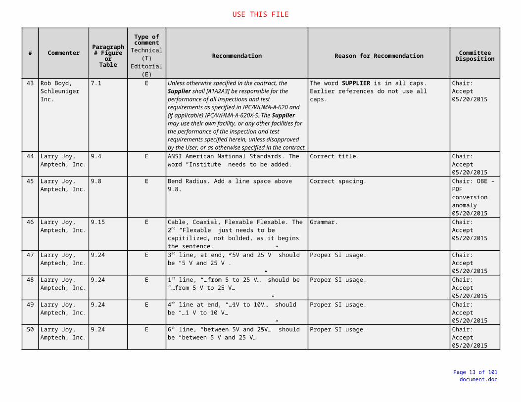
43 Rob Boyd, Schleuniger Inc.
7.1 E Unless otherwise specified in the contract, the Supplier shall [A1A2A3] be responsible for the performance of all inspections and test requirements as specified in IPC/WHMA-A-620 and (if applicable) IPC/WHMA-A-620X-S. The Supplier may use their own facility, or any other facilities for the performance of the inspection and test requirements specified herein, unless disapproved by the User, or as otherwise specified in the contract.
The word SUPPLIER is in all caps. Earlier references do not use all caps.
Chair: Accept 05/20/2015
44 Larry Joy, Amptech, Inc.
9.4 E ANSI American National Standards. The word “Institute” needs to be added.
Correct title. Chair: Accept 05/20/2015
45 Larry Joy, Amptech, Inc.
9.8 E Bend Radius. Add a line space above 9.8. Correct spacing. Chair: OBE – PDF conversion anomaly05/20/2015
46 Larry Joy, Amptech, Inc.
9.15 E Cable, Coaxial, Flexable Flexable. The 2nd “Flexable” just needs to be capitilized, not bolded, as it begins the sentence.
Grammar. Chair: Accept 05/20/2015
47 Larry Joy, Amptech, Inc.
9.24 E 3rd line, at end, “5V and 25 V” should be “5 V and 25 V”.
Proper SI usage. Chair: Accept 05/20/2015
48 Larry Joy, Amptech, Inc.
9.24 E 1st line, “…from 5 to 25 V…” should be “…from 5 V to 25 V…
Proper SI usage. Chair: Accept 05/20/2015
49 Larry Joy, Amptech, Inc.
9.24 E 4th line at end, “…1V to 10V…” should be “…1 V to 10 V…”
Proper SI usage. Chair: Accept 05/20/2015
50 Larry Joy, Amptech, Inc.
9.24 E 6th line, “between 5V and 25V…” should be “between 5 V and 25 V…”
Proper SI usage. Chair: Accept 05/20/2015
51 Larry Joy, Amptech, Inc.
9.24 E Last line, “between 1V and 10V.” should be “between 1 V and 10 V.”
Proper SI usage. Chair: Accept 05/20/2015
52 Larry Joy, Amptech, Inc.
9.24 E In this clause and throughout the document the word “microsecond” or “microseconds” should be replaced with “µs”.
Proper SI usage. Chair: Accept 05/20/2015
53 Larry Joy, Amptech, Inc.
9.25 E 1st line, “…below 10V and less than 5A…” should be “…below 10 V and less than 5 A…”.
Proper SI usage. Chair: Accept 05/20/2015
54 Larry Joy, Amptech, Inc.
9.25 E 2nd line, “…less than 1V…” should be “…less than 1 V…”
Proper SI usage. Chair: Accept 05/20/2015
55 Larry Joy, Amptech, Inc.
9.25 E 3rd line, “…less than 5V…” and “…less than 1V…” should be “…less than 5 V…” and “…less than 1 V…”.
Proper SI usage. Chair: Accept 05/20/2015
56 Larry Joy, Amptech, Inc.
9.25 E 4th line, “…less than 5V…” should be “…less than 5 V…”.
Proper SI usage. Chair: Accept 05/20/2015
57 Larry Joy, Amptech, Inc.
9.27 E 2nd line, “10V” should be “10 V”. Proper SI usage Chair: Accept 05/20/2015
Page 8 of 66document.doc

USE THIS FILE
# Commenter Paragraph # Figure or
Table
Type of comment
Technical (T)Editorial (E)
Recommendation Reason for Recommendation Committee Disposition
58 Larry Joy, Amptech, Inc.
9.29 E 2nd line, “10V” should be “10 V” in two places. Proper SI usage. Chair: Accept 05/20/2015
59 Larry Joy, Amptech, Inc.
9.29 E 3rd line, “25V” should be “25 V”. Proper SI usage. Chair: Accept 05/20/2015
60 Larry Joy, Amptech, Inc.
9.30.1 E 1st line, “10V” and “5A” should be “10 V” and “5 A” respectively.
Proper SI usage. Chair: Accept 05/20/2015
61 Larry Joy, Amptech, Inc.
9.30.1 E 2nd line, “1V” should be “1 V”. Proper SI usage. Chair: Accept 05/20/2015
62 Larry Joy, Amptech, Inc.
9.30.1 E 3rd line, “5V” should be “5 V” and “1V” should be “1 V”.
Proper SI usage. Chair: Accept 05/20/2015
63 Larry Joy, Amptech, Inc.
9.30.1 E 4th line, “5 V” should be “5 V”. Proper SI usage. Chair: Accept 05/20/2015
64 Larry Joy, Amptech, Inc.
9.30.2 E 1st line, “5 to 25 V” should be “5 V to 25 V”. Proper SI usage. Chair: Accept 05/20/2015
65 Larry Joy, Amptech, Inc.
9.43 E At the end, “Torr” should be “torr”. Units of measure are considered common nouns and are not capitilized.
Grammar. Chair: Accept 05/20/2015
66 Larry Joy, Amptech, Inc.
9.47 E Change “Association” to “Alliance”. Proper name title Chair: Accept 05/20/2015
67 Stefan Hanigk, Airbus
Apendix A; Reference 4.5.20 (new)(4.6.20 <New>)
T It was not defined what is a military application/product, and what is called a space application/product.
It is not defined whether it is to use risk to the application or for the people who applied.
NEW:Parylene-C coatings shall not be used without user approval.
In space applications, it may be that extreme mechanical loads in the starting phase and thermal cyclic stresses occur during operation. In addition, an operation in vacuum.For military applications, there is a long-term mechanical stress without vacuum.There is an unclear definition of military space applications (e.g. satellites).
Chair: See draft for possible resolution.
Parylene (Poly-Paraxylene) Coatings Containing Chlorine (Cl)Parylene-C coatings shall not be used without prior User approval.Rationale: Thermal decomposition of this product (exposure to high heat applications or contact with flame) can produce irritating vapors, acrid smoke, and toxic gases (i.e.: chlorine, carbon monoxide, dioxins, furans, hydrogen chloride, and carbon dioxide).
Accept / modify 06/16/2015
Page 9 of 66document.doc

USE THIS FILE
# Commenter Paragraph # Figure or
Table
Type of comment
Technical (T)Editorial (E)
Recommendation Reason for Recommendation Committee Disposition
68 Barrie Dunn, School of Engineering, University of Portsmouth, UK
Appendix B T Cert. ProcessesStorage shelf life: add: silver-coated copper wire that has passed the red-plague corrosion test (e.g ECSS Q-70-20), or wires that have full traceability that ensures they have been stored in dry, nitrogen filled bags or other containers with activated desiccant (ref 3.6.1.d) should have unlimited storage life. Wire refers to cut lengths or long stranded wires and cables stored on reels.
No reason provided. Contact information available.
Chair: Not sure how to disposition.
Deferred to WP-01306/16
69 Barrie Dunn, School of Engineering, University of Portsmouth, UK
WP-013 RED
PLAGUE CONTROL
PLAN
T This is a useful document, Good to see the ESA work is cited and ECSS Q-ST-70-20 is a Ref Doc. In Europe this standard is applied by all the wire and cable manufacturers supplying to ESA spacecraft. Years of experience with this standard and its requirement for routine Anthony and Brown testing has prevented the red plague problems seen in earlier years. After the ref to my book .......Wiley-Praxis; 1997; ISBN 0-471-96428-X you could indicate (the revised edition of this book will be published by Springer at end-2015).
See recommendation.
Chair: Unable to reference a publication that has not been released.
Defer to committee and IPC for resolution.
Defer to next revision, because we cannot reference a document that has not been released.
70 Larry Joy, Amptech, Inc.
WP-013 RED PLAGUE CONTROL PLAN Page 2, Chemical attack.
E 4th line, “…often contain and outgas small amounts of sulfur.” Think this should be “…often contain an outgas of small amounts of sulfur.”
Grammar Chair: Accept / mod. 05/27/2015
71 Larry Joy, Amptech, Inc.
WP-013 RED PLAGUE CONTROL PLAN Page 2, FIGURE 2.
E There are several pictures that overlap and block some text. Rearrange the pictures and text as necessary.
To make presentation clear. Chair: This is an artifact of the pdf generation process. Will be corrected in typesetting
Page 10 of 66document.doc

USE THIS FILE
# Commenter Paragraph # Figure or
Table
Type of comment
Technical (T)Editorial (E)
Recommendation Reason for Recommendation Committee Disposition
72 Jim Blanche and Garry McGuire, MARSHALL FLIGHT SPACE CENTER
WP-013 RED PLAGUE CONTROL Global
T Delete all “/cupric”. Red plague is cuprous oxide, not cupric oxide. Chair: Accept as global change to document. 05/27/2015
73 Jim Blanche and Garry McGuire, MARSHALL FLIGHT SPACE CENTER
WP-013 RED PLAGUE CONTROL Global
E After the first paragraph, delete all “cuprous oxide corrosion” and just call it Red Plague in the document.
It is called a Red Plague Control Plan. Once it is defined in the 1st paragraph, there is no reason to constantly keep repeating it.
Chair: Accept as global change to document. 05/27/2015
74 Jim Blanche and Garry McGuire, MARSHALL FLIGHT SPACE CENTER
WP-013 RED PLAGUE CONTROL Page 2
E Delete the paragraphs for “Inadequate Silver Coating Thickness”, “High Temperature”, and “Chemical Attack”.
They are repeats of the three paragraphs in front of them.
Chair: Accept. 05/27/2015
75 Jim Blanche and Garry McGuire, MARSHALL FLIGHT SPACE CENTER
WP-013 RED PLAGUE CONTROL Page 2
T Top paragraph, last sentence - Exposure to atomic oxygen (AO) in spaceflight applications has been shown to tarnish and pit silver coatings.
Clarify or delete
This condition should preclude red plague since being in space would eliminate the moisture necessary for the galvanic couple?
Chair: See suggested resolution of comment in draft
Accept 06/23/2015
76 Jim Blanche and Garry McGuire, MARSHALL FLIGHT SPACE CENTER
WP-013 RED PLAGUE CONTROL Page 2
T From: High Temperature, last sentence - This effect is typically experienced only in long duration operation at temperatures beyond the wire’s continuous rating, or in instances where the wiring is exposed to excessive heat during test or highly accelerated burn-in.
To: High Temperature - This effect is typically experienced in instances where the wiring is exposed to excessive heat during test or highly accelerated burn-in.
If the wire is going to be operated above its continuous rating for long durations there may be bigger problems than Red Plague that does not rapidly cause failure.
Chair: See suggested resolution of comment in draft
High Temperature Though the upper continuous operating temperature rating of most silver-coated wiring is +200 °C [+392 °F], exposure to temperatures approaching +200 °C [+392 °F] or higher, induces migration of the copper base metal through the silver coating. This may reduce the silver coating thickness and create porosity sites for cuprous/cupric oxide corrosion to occur. This effect is typically experienced in instances where the wiring is exposed to excessive heat during test or highly accelerated burn-in.
Accept 06/23/15
Page 11 of 66document.doc

USE THIS FILE
# Commenter Paragraph # Figure or
Table
Type of comment
Technical (T)Editorial (E)
Recommendation Reason for Recommendation Committee Disposition
77 Jim Blanche and Garry McGuire, MARSHALL FLIGHT SPACE CENTER
WP-013 RED PLAGUE CONTROL 1.4
E Reword to:The authority for this document derives from the Red Plague Control requirements in the space addendums (addenda?) to IPC/WHMA-A-620, Requirements and Acceptance for Cable and Wire Harness Assemblies, and IPC J-STD-001, Requirements for Soldered Electrical and Electronic Assemblies.
The documents cited should not be revision specific since this white paper will probably exist in perpetuity.For the same reason, there is no reason to cite the specific clause numbers as they may change over time.
Chair: Accept 05/27/2015
78 Jim Blanche and Garry McGuire, MARSHALL FLIGHT SPACE CENTER
WP-013 RED PLAGUE CONTROL 1.5
T?E
(rwc: 05/27/2015)
1st sentence: Delete “design”. The reason for taking this out of the design document was so that it can apply to storage and fabrication processes as well.
Chair: Change this comment to Editorial (E) and accept. 05/27/2015
79 Jim Blanche and Garry McGuire, MARSHALL FLIGHT SPACE CENTER
WP-013 RED PLAGUE CONTROL 1.9.b & .c
E Delete one of these. These are redundant. The “less stringent” plan allowed by “c” is still an alternate control plan.
Chair: Deleted (c) as redundant to the intent of (b).Accept 05/27/2015
80 Jim Blanche and Garry McGuire, MARSHALL FLIGHT SPACE CENTER
WP-013 RED PLAGUE CONTROL Table B-1
T Label the third column - Coating Thickness, or change the title of the table to Table B-1 Conductor Strand Material and Coating Thickness.
Just “Thickness” is subject to misinterpretation as the strand thickness, even though 3.2 immediately following does clarify it.
Chair: See suggested resolution of comment in draft
Accept 06/23/15
81 Larry Joy, Amptech, Inc.
WP-013 RED PLAGUE CONTROL PLAN 2.4 REFERENCE DOCUMENTS.
E 1st line, “…these documents fall in order…” Close up the space, should be, “…these documents fall in order…”
Proper editing. Chair: The spacing issue noted is an artifact of the pdf conversion.
82 Larry Joy, Amptech, Inc.
WP-013 RED PLAGUE CONTROL PLAN 3.2.1.
E “1 Micrometer…” should be “1 µm…” Proper SI usage. Chair: Accept 05/27/2015
Page 12 of 66document.doc
USE THIS FILE
# Commenter Paragraph # Figure or
Table
Type of comment
Technical (T)Editorial (E)
Recommendation Reason for Recommendation Committee Disposition
83 Jim Blanche and Garry McGuire, MARSHALL FLIGHT SPACE CENTER
3.2.1 T Primary and shield conductors shall have a coating thickness of not less than 1 μm [~40 μin] average, when measured in accordance with ASTM B 298-07.
Average is made up of less than and more than the average. “Not less than X average” is as meaningless as “average minimum” thickness for copper plating on a through-hole wall. If ASTM B 298-07 takes an average then the 1µm is still ok.
Chair: Accept 05/27/2015
84 Larry Joy, Amptech, Inc.
WP-013 RED PLAGUE CONTROL PLAN 3.2.2.
E “2 Micrometer…” should be “2 µm…” Proper SI usage. Chair: Accept 05/27/2015
85 Jim Blanche and Garry McGuire, MARSHALL FLIGHT SPACE CENTER
WP-013 RED PLAGUE CONTROL PLAN 3.2.2
T See above comment to 3.2.1…Delete “average”. Chair: Accept 05/27/2015
86 Jim Blanche and Garry McGuire, MARSHALL FLIGHT SPACE CENTER
WP-013 RED PLAGUE CONTROL PLAN 3.2.2
T Conflicts with 3.2.1 It doubles the thickness for the same thing. – Clarify the difference.
Chair: See suggested resolution of comment in draft
Accept 06/23/15
87 Jim Blanche and Garry McGuire, MARSHALL FLIGHT SPACE CENTER
WP-013 RED PLAGUE CONTROL PLAN 3.2.3
E Correct the list to a. b. and c. rather than a. a. c. Typo Chair: Accept 05/27/2015
88
244T
Jim Blanche and Garry McGuire, MARSHALL FLIGHT SPACE CENTER
WP-013 RED PLAGUE CONTROL PLAN 3.2.3
T Second a. - Must samples of every roll of wire be microsectioned and analyzed by a lab certified to IPC-QL-653A or it that done by the wire manufacturer?
Chair: “or as agreed upon by the User” should allow the use of the wire manufacturer’s facility.
Accept 06/23/15, 244T OBE by 88T
89 Jim Blanche and Garry McGuire, MARSHALL FLIGHT SPACE CENTER
WP-013 RED PLAGUE CONTROL PLAN 3.4
T/E ? White Plague – Reference WP-014 here. Or delete this clause because a white paper on white plague exists.
Make sure the reader knows WP-014 exists
Chair: see proposed resolution in draft.
Accept 06/23/15
90 Jim Blanche and Garry McGuire, MARSHALL FLIGHT SPACE CENTER
WP-013 RED PLAGUE CONTROL PLAN 3.5
T Limited Life Article - Document what action, if any, is called for with a cable incorporating silver-coated copper conductors that has been in use for more than ten years
Clarity
Chair: See second sentence.
Accept 06/23/15
Page 13 of 66document.doc

USE THIS FILE
# Commenter Paragraph # Figure or
Table
Type of comment
Technical (T)Editorial (E)
Recommendation Reason for Recommendation Committee Disposition
91 Jim Blanche and Garry McGuire, MARSHALL FLIGHT SPACE CENTER
WP-013 RED PLAGUE CONTROL PLAN 3.6
E Add a space between the clause title and start of 1st sentence.
Chair: Accept 05/27/2015
Page 14 of 66document.doc

USE THIS FILE
# Commenter Paragraph # Figure or
Table
Type of comment
Technical (T)Editorial (E)
Recommendation Reason for Recommendation Committee Disposition
92 Jim Blanche and Garry McGuire, MARSHALL FLIGHT SPACE CENTER
WP-013 RED PLAGUE CONTROL PLAN 3.6.1 & 3.6.1.e.(2)
T Delete “irreversible” in both sentences. Discussions during the 2014 Fall Meeting for 001FS resulted in the committee not using reversible or irreversible in the text, just requiring a humidity indicator card. Garry McGuire proposed during that meeting to allow only irreversible cards but was soundly rejected by the committee (I think availability in the real world was the issue but I’m not sure).The 620 space addendum will probably follow this lead when 620CS opens for revision.
Chair:1. See proposed resolution in draft.2. Definition updated [5.8]
Chair: Irreversible (Maximum) Humidity Indicator Cards are available from the following:Texas Technologies (https://texastechnologies.com/moisture-control/humidity-indicators/cards/non-reversible-humidity-indicator.htm)Mid-South Packaging Inc. (www.midsouthpackaging.com)Telatemp (http://www.telatemp.com/c/172/humidity-indicator-cards)AGM Container (http://www.agmcontainer.com/products/hi-cards.html)James Dawson Enterprises (http://packagingmaterial.jamesdawson.com/item/humidity-indicators/humidity-indicator-cards/mx56789)Clariant (http://www.clariant.com/en/Solutions/Products/2013/12/09/18/28/Humidity-Indicator-Cards--Humidity-Indicator-Plugs)Cole-Parmer (http://www.coleparmer.com/Product/Cole_Parmer_NIST_Traceable_Humidity_Card_6_pk/EW-03313-06)Dry Pak Industries (http://www.drypak.com/humidityIndicatingCards.html)
Comment withdrawn, but inserted “Maximum” to correctly identify the technology by its industry term.06/23/15
Page 15 of 66document.doc

USE THIS FILE
# Commenter Paragraph # Figure or
Table
Type of comment
Technical (T)Editorial (E)
Recommendation Reason for Recommendation Committee Disposition
93 Jim Blanche and Garry McGuire, MARSHALL FLIGHT SPACE CENTER
WP-013 RED PLAGUE CONTROL PLAN 3.6.1.e.(2)
T Clarify how this humidity indicator (quality record) must be stored to assure it does not change over time.
If it were to see higher or lower humidity in storage it would change its reading. Perhaps the reading at the time of receipt should be recorded and that should become the quality record. Chair: see proposed resolution in draft.
accepted as modified 06/23
94 Larry Joy, Amptech, Inc.
WP-013 RED PLAGUE CONTROL PLAN 3.6.1g.
E 2nd line, “…for a period of 24 hours…” should be “…for a period of 24 h…”
Proper SI usage.
Chair: Agree that “24 h” is the proper SI format, but suggestion is to leave as “24 hours” to minimize reader confusion.
Not accept. Committee decision was to leave as “24 hours” to minimize reader confusion.06/23/2015
95 Larry Joy, Amptech, Inc.
WP-013 RED PLAGUE CONTROL PLAN 3.6.2.
E 2nd line, “…relative humidity is less than 70%RH.” This should be, “…relative humidity is < 70 %.” It is redundant to say relative humidity and put RH.
Grammar. Chair: Accept/mod. to improve readability 05/27/2015
96 Jim Blanche and Garry McGuire, MARSHALL FLIGHT SPACE CENTER
WP-013 RED PLAGUE CONTROL PLAN 3.6.2.b
T 1st sentence: Change pointer from 4.1.c to 4. There are two methods for capping in section 4 so the pointer shouldn’t be so specific.
Chair: see proposed resolution in draft.
Accept 06/23/15
97 Jim Blanche and Garry McGuire, MARSHALL FLIGHT SPACE CENTER
WP-013 RED PLAGUE CONTROL PLAN 3.6.2.b
T 2nd sentence: Fix the pointer to 4.1. There is no storage discussed in Section 4….maybe a pointer back to 3.6.1?
Chair: see proposed resolution in draft.
Accept with modification, 06/23/15
98 Larry Joy, Amptech, Inc.
WP-013 RED PLAGUE CONTROL PLAN 3.6.2c.<3.6.2.d>
E Same as 3.6.2. Grammar. Chair: Accept/mod. 05/28/2015
99 Jim Blanche and Garry McGuire, MARSHALL FLIGHT SPACE CENTER
WP-013 RED PLAGUE CONTROL PLAN 3.7
T 2nd sentence: Change “Material Review Board (MRB) to “authority”.
This document will have broad applications. Not all contracts, organizations, or programs use MRBs.
Chair: see proposed resolution in draft.
Accept / modify 06/23/2015
Page 16 of 66document.doc

USE THIS FILE
# Commenter Paragraph # Figure or
Table
Type of comment
Technical (T)Editorial (E)
Recommendation Reason for Recommendation Committee Disposition
100 Jim Blanche and Garry McGuire, MARSHALL FLIGHT SPACE CENTER
WP-013 RED PLAGUE CONTROL PLAN 3.7
T Deleted “[See 6, NONCONFORMANCE]”. There is no Section 6. An organization’s quality system will have a defined process for handling non-conformances.
Chair: OBE, reference changed to 3.9.
101 Jim Blanche and Garry McGuire, MARSHALL FLIGHT SPACE CENTER
WP-013 RED PLAGUE CONTROL PLAN 3.7.1.b
Use increased magnification than the ranges listed in J-STD-001 or A-620. Recommend a single magnification of least 10X or 20X.
The magnification ranges is the referenced standards are based on land size or wire gauge and range from 1.5X to 20X depending on feature sizes. Red plague, especially in the onset stages can be difficult to see and doesn’t care what wire size it is on. For instance – per A-620, wires larger than 14AWG require no magnification.
Chair: see proposed resolution in draft.
Accept / modify 06/23/15
102 Larry Joy, Amptech, Inc.
WP-013 RED PLAGUE CONTROL PLAN 3.7.1c.
E Note: “…from 3000 – 5000 K…” should be “…from 3000 K to 5000 K…”
Proper SI usage. Chair: Accept / modify. Instead of suggested “3000 K to 5000 K” changed to “3000 to 5000 K” to improve readability.05/28/2015
103 Larry Joy, Amptech, Inc.
WP-013 RED PLAGUE CONTROL PLAN 3.7.2.
E Same as 3.6.2 Grammar. Chair: Accept/mod. 05/28/2015
104 Jim Blanche and Garry McGuire, MARSHALL FLIGHT SPACE CENTER
WP-013 RED PLAGUE CONTROL PLAN 3.8.2.b
E “cooper wire” should be “ copper wire”. Typo Chair: Accept 05/28/2015
105 Jim Blanche and Garry McGuire, MARSHALL FLIGHT SPACE CENTER
WP-013 RED PLAGUE CONTROL PLAN 3.8.2.b
T Either delete “heavier plating thickness” from the parenthetical statement or delete everything after the parenthetical statement. I recommend the latter.
It doesn’t matter how thick the plating is, it will not protect the cut end of the conductor. However, a heavier thickness will be less prone to exposing copper at the location the tool indenters form the crimp. Chair: See proposed resolution in draft.
Accept <IC-105T> as modified 06/23/2015
Page 17 of 66document.doc

USE THIS FILE
# Commenter Paragraph # Figure or
Table
Type of comment
Technical (T)Editorial (E)
Recommendation Reason for Recommendation Committee Disposition
106 Jim Blanche and Garry McGuire, MARSHALL FLIGHT SPACE CENTER
WP-013 RED PLAGUE CONTROL PLAN 3.9
T This is awfully specific. Recommend just saying something like “Nonconformances shall be processed in accordance with the Manufacturer’s Quality System.”If this is not accepted, “MRB” in “c” should be changed to “authority” if the similar previous comment to 3.7 was accepted.
Any organization required to have this plan will most likely be required to be compliant to ISO 9000 or AS9100. They will have a very well defined process for handling non-conforming products. We don’t need to tell them how to do it here.
Chair: See draft
Accept Option 1, deleted (a) – (d)06/23/15
107 Larry Joy, Amptech, Inc.
WP-013 RED PLAGUE CONTROL PLAN 4.1e.
E 2nd line, “Hold pressure on the ‘tail’ for 20 to 40 seconds…” should be “Hold pressure on the ‘tail’ for 20 s to 40 s…”
Proper SI usage.
Chair: Agree that 20 s to 40 s is the proper SI format, but suggestion is to leave as “20 to 40 seconds” to minimize reader confusion.
Not accepted. Committee decision was to leave as “20 to 40 seconds” to minimize reader confusion.06/23/2015
108 Larry Joy, Amptech, Inc.
WP-013 RED PLAGUE CONTROL PLAN 5.16.
E 2nd line, “…+77 °F [+25 °C]…” should be “…+25 °C [+77 °F]…’ And “3 gm” should be “3 g”.
Proper SI usage. Chair: Accept 05/28/2015
109 Larry Joy, Amptech, Inc.
WP-013 RED PLAGUE CONTROL PLAN 5.16.
E 3rd line, “6 gm” should be “6 g”. Proper SI usage. Chair: Accept 05/28/2015
Page 18 of 66document.doc

USE THIS FILE
# Commenter Paragraph # Figure or
Table
Type of comment
Technical (T)Editorial (E)
Recommendation Reason for Recommendation Committee Disposition
110 Dave Hillman, Rockwell Collins
White Paper WP-013And White WP-014
Technical The 620 committee should either: (1) needs to move these documents into the 620 Handbook with significant reformatting or (2) make this document a true Appendix of the 620 specification
Per the IPC Committee Chairman’s Handbook:
“7.3 Technical Reports, Technical Papers and White Papers
There will be times when your committee feels there is a need for published data about a specific area of technology which is either not addressed or current with the times. These reports can fill a need found during the development of a standard or publication or may come from a request by someone or a group of people in the industry. Many technical reports and technical papers are a result of round robin testing programs. These reports and papers can follow a similar format to the IPC Standardization Procedures, but they do not have to meet the procedures. To assure relevance, these reports should go through some level of peer review by a committee or group of SMEs. The final report or paper will be submitted to the TAEC for review and approval. “
The current WP-013/014 is not a white paper per the CC Handbook definition. The WP-013/014 is written as a actionable specification addressing a technical topic germane to the 620 specification. If the committee intention is to have the industry utilize WP-013/014 as a contractionable control plan addressing Red/White Plague then the technical descriptive information would be best suited in the 620 Handbook and the remaining material as an Appendix that could be selected and invoked as part of the overall 620 specification design protocols.
Defer to IPC Staff for resolution / mediation
Page 19 of 66document.doc

USE THIS FILE
# Commenter Paragraph # Figure or
Table
Type of comment
Technical (T)Editorial (E)
Recommendation Reason for Recommendation Committee Disposition
111 Jim Blanche and Garry McGuire, MARSHALL FLIGHT SPACE CENTER
WP-014 WHITE PLAGUE CONTROL PLAN General
T The control requirements for White Plague appear to be identical to the control requirements for Red Plague other than specifying the allowable rate of fluorine outgassing.
Does it need to be a separate white paper? Have always heard the mitigation for white plague was to not store in in a sealed environment, allowing all the bad stuff to dissipate into the air. Recommend discussing this with the engineers at GSFC who first brought this to light. “Red” and “White” should be the same paper if the controls are the same.
Chair comment: The basic control requirements for Red Plague and White Plague are identical, given that the conductor constructions (silver-coated copper) are the same. The issue is control and mitigation of fluorine outgassing during shipping and storage.
Chair: See proposed resolution in draft. Affected by change: 3.1.b; 3.2.1; 3.2.2 (new)
Accept 06/30/2015
112 Barrie Dunn, School of Engineering, University of Portsmouth, UK
WP-014 WHITE
PLAGUE CONTROL
PLAN
T A better Figure D1 with a cleaner cut insulation is preferred.
Clarity
Chair: proposal is to add an arrow to indicate area of concern. See draft.
Accept as modified with an increased magnification and an arrow.06/30/15
113 Jim Blanche and Garry McGuire, MARSHALL FLIGHT SPACE CENTER
WP-014 WHITE PLAGUE CONTROL PLAN 1.4
E Reword to:The authority for this document derives from the White Plague Control requirements in the space addendum to IPC/WHMA-A-620, Requirements and Acceptance for Cable and Wire Harness Assemblies.
The document cited should not be revision specific since this white paper will probably exist in perpetuity.For the same reason, there is no reason to cite the specific clause number as it may also change over time.
Chair: Accept 05/28/2015
114 Jim Blanche and Garry McGuire, MARSHALL FLIGHT SPACE CENTER
WP-014 WHITE PLAGUE CONTROL PLAN 1.5
T? 1st sentence: Delete “design”. The reason for taking this out of the design document was so that it can apply to storage and fabrication processes as well.
Chair: Change this comment to Editorial (E) and accept. 05/28/2015
Page 20 of 66document.doc

USE THIS FILE
# Commenter Paragraph # Figure or
Table
Type of comment
Technical (T)Editorial (E)
Recommendation Reason for Recommendation Committee Disposition
115 Jim Blanche and Garry McGuire, MARSHALL FLIGHT SPACE CENTER
WP-014 WHITE PLAGUE CONTROL PLAN 1.5.1
E Second sentence – From: When this standard is contractually invoked, the applicable requirements of this standard shall be imposed on all applicable subcontracts, assembly drawing(s), documentation and purchase orders
To: When the requirements of this document are contractually invoked, the applicable requirements of this document shall be imposed on all applicable subcontracts, assembly drawing(s), documentation and purchase orders.
This is a White Paper and not a standard. If it is to be called a standard its title should be changed.
Chair: OBE by rewrite to match WP-013 language. 05/28/2015
116
79E
Jim Blanche and Garry McGuire, MARSHALL FLIGHT SPACE CENTER
WP-014 WHITE PLAGUE CONTROL PLAN 1.9
E Approval of Departures from this Document- delete a. thru d.
The lead-in sentence covers all 4 of these items
Chair: The wording of this section is virtually identical to the recommended change to the same section in WP-013. Recommendation is to either (a) synergize this document to WP-013, or (b) delete a-c (d) in both documents.
Chair: See proposed resolution in draft – synergy to WP-013 [1.9], comment <IC-79E>.
Any changes, revisions, or deviations to this document or to the requirements referenced by this document shall require technical evaluation and approval by the User prior to handling or processing of hardware.a. Oral statements shall not be permitted in any
manner or degree to modify or otherwise affect the requirements of any portion of this document.
b. Use of alternate control plans, documents, or processes shall require review and approval of the User prior to use.
c. Requests for relief from requirements in this document shall require review and approval of the User prior to use.
Chair: OBE to <IC-79E>
Chair: Accept 05/27/2015
Accept as global change. 06/30/15
117 Larry Joy, Amptech, Inc.
WP-014 WHITE PLAGUE CONTROL PLAN 3.1a.
E 1st line, “…of th insulation…” should be “…of the insulation…”
Typographical error. Typo. Accept 05/29/2015
Page 21 of 66document.doc

USE THIS FILE
# Commenter Paragraph # Figure or
Table
Type of comment
Technical (T)Editorial (E)
Recommendation Reason for Recommendation Committee Disposition
118 Larry Joy, Amptech, Inc.
WP-014 WHITE PLAGUE CONTROL PLAN 3.1b.
E 2nd line, “24 hours” should be “24 h”. Proper SI usage.
Chair: Agree that 24 h is the proper SI format, but suggestion is to leave as “24 hours” to minimize reader confusion.
Not accept. Committee decision was to leave as “24 hours” to minimize reader confusion.06/23/2015
Page 22 of 66document.doc

USE THIS FILE
# Commenter Paragraph # Figure or
Table
Type of comment
Technical (T)Editorial (E)
Recommendation Reason for Recommendation Committee Disposition
119 Jim Blanche and Garry McGuire, MARSHALL FLIGHT SPACE CENTER
WP-014 WHITE PLAGUE CONTROL PLAN 3.2.1 & 3.2.1.d
Delete “irreversible” in both sentences. Discussions during the 2014 Fall Meeting for 001FS resulted in the committee not using reversible or irreversible in the text, just requiring a humidity indicator card. Garry McGuire proposed during that meeting to allow only irreversible cards but was soundly rejected by the committee (I think availability in the real world was the issue but I’m not sure).The 620 space addendum will probably follow this lead when 620CS opens for revision.
Chair: 1. See proposed resolution in draft. 2. Definition updated, see [5.8]
Chair: Irreversible (Maximum) Humidity Indicator Cards are available from the following:Texas Technologies (https://texastechnologies.com/moisture-control/humidity-indicators/cards/non-reversible-humidity-indicator.htm)Mid-South Packaging Inc. (www.midsouthpackaging.com)Telatemp (http://www.telatemp.com/c/172/humidity-indicator-cards)AGM Container (http://www.agmcontainer.com/products/hi-cards.html)James Dawson Enterprises (http://packagingmaterial.jamesdawson.com/item/humidity-indicators/humidity-indicator-cards/mx56789)Clariant (http://www.clariant.com/en/Solutions/Products/2013/12/09/18/28/Humidity-Indicator-Cards--Humidity-Indicator-Plugs)Cole-Parmer (http://www.coleparmer.com/Product/Cole_Parmer_NIST_Traceable_Humidity_Card_6_pk/EW-03313-06)Dry Pak Industries (http://www.drypak.com/humidityIndicatingCards.html)
Withdrawn06/30/15
OBE by 013
Page 23 of 66document.doc

USE THIS FILE
# Commenter Paragraph # Figure or
Table
Type of comment
Technical (T)Editorial (E)
Recommendation Reason for Recommendation Committee Disposition
120 Jim Blanche and Garry McGuire, MARSHALL FLIGHT SPACE CENTER
WP-014 WHITE PLAGUE CONTROL PLAN 3.2.1.d.(2)
T Clarify how must it be stored to assure it cannot change.
It is a Quality Record (QR) that is subject to change if it sees higher humidity in storage. Chair: see proposed resolution in draft.
OBE by 013
121 Jim Blanche and Garry McGuire, MARSHALL FLIGHT SPACE CENTER
WP-014 WHITE PLAGUE CONTROL PLAN 3.3
T 2nd sentence: Change “Material Review Board (MRB) to “authority”.
This document will have broad applications. Not all contracts, organizations, or programs use MRBs. Chair: see proposed resolution in draft.
OBE by 013 change06/30/15
122 Larry Joy, Amptech, Inc.
WP-014 WHITE PLAGUE CONTROL PLAN 3.3.1c Note.
E 2nd line, “…from 3000 – 5000°K…” should be “…from 3000 K to 5000 K…”
Proper SI usage.
Chair: Instead of suggested “3000 K to 5000 K” changed to “3000 to 5000 K” to minimize reader confusion.
Chair: Accept / modify. 05/28/2015
123 Larry Joy, Amptech, Inc.
WP-014 WHITE PLAGUE CONTROL PLAN 3.3.1e.
E 3rd (last) line, “…and the relative humidity is less than 70% RH.” Should be, “…and the relative humidity is < 70%.” Or “…and < 70% RH.”
Grammar. Chair: Accept/mod. to improve readability 05/29/2015
124 Larry Joy, Amptech, Inc.
WP-014 WHITE PLAGUE CONTROL PLAN 4.1e.
E 2nd line, “Maintain pressure on the ‘tail’ for 20 to 40 seconds…” Should be, “Maintain pressure on the ‘tail’ for 20 s to 40 s…”
Proper SI usage.
Chair: Agree that 20 s to 40 s is the proper SI format, but suggestion is to leave as "20 to 40 seconds” to minimize reader confusion.
OBE by 01306/30/15
125 Jim Blanche and Garry McGuire, MARSHALL FLIGHT SPACE CENTER
WP-014 WHITE PLAGUE CONTROL PLAN 3.3.1.e
E The paragraph references are not correct. I think 5.1.d should be 3.3.1.d and 4.1 should be 3.2.1.
Chair: Accept/mod.05/29/2015
126 Jim Blanche and Garry McGuire, MARSHALL FLIGHT SPACE CENTER
WP-014 WHITE PLAGUE CONTROL PLAN 3.4.a
E Change reference to 5.1.d to [I think] 3.3.1.d. OBE: 05/29/2015
Page 24 of 66document.doc

USE THIS FILE
# Commenter Paragraph # Figure or
Table
Type of comment
Technical (T)Editorial (E)
Recommendation Reason for Recommendation Committee Disposition
127 Jim Blanche and Garry McGuire, MARSHALL FLIGHT SPACE CENTER
WP-014 WHITE PLAGUE CONTROL PLAN 7 which is actually after 3.4 and before 4
T Reword to: Nonconformances shall be processed in accordance with the Manufacturer’s Quality System.”If this is not accepted, “MRB” in “c” should be changed to “authority” if the similar previous comment to 3.7 was accepted.
Any organization required to have this plan will most likely be required to be compliant to ISO 9000 or AS9100. They will have a very well defined process for handling non-conforming products. We don’t need to tell them how to do it here.
Chair: see proposed resolution in draft.
Resolved in 13. Bob make sure words are identical.
Accept / mod 06/30/15
128 Jim Blanche and Garry McGuire, MARSHALL FLIGHT SPACE CENTER
WP-014 WHITE PLAGUE CONTROL PLAN 4.2
T Delete the 2nd sentence. The requirement is to “seal by coating and saturating the exposed end…”. User approval should not be required for different ways to accomplish it.
Chair: Potential synergy issue with WP-013 [4.2], as that paragraph is unchanged by IC Review. Requested deletion of second sentence is non-technical, as no requirement is levied.
Chair: see proposed resolution in draft
Accept 06/30/15.Global to 013.Completed in 013
129 Larry Joy, Amptech, Inc.
WP-014 WHITE PLAGUE CONTROL PLAN 5.10.
E 2nd line, “air at +77 °F [+25 °C]…” should be “air at +25 °C [+77 °F]…”
Proper SI usage. Chair: Accept 05/29/2015
130 Dave Hillman, Rockwell Collins
White Paper WP-015
Technical The 620 committee should either: (1) move this document into the 620 Handbook with significant reformatting or (2) refer this white paper to the IPC PERM Council for action/implementation and have it removed from inclusion in the 620 specification or (3) include the white paper as an invokeable appendix with significant reformatting addressing the specific topic cable and wire harness assemblies in such a manner as to not conflict with the existing IPC PERM Council LFCP specification.
Several significant issues with this white paper:
(1) Per the IPC Committee Chairman’s Handbook:
“7.3 Technical Reports, Technical Papers and White Papers
There will be times when your committee feels there is a need for published data about a specific area of technology which is either not addressed or current with the times. These reports can fill a need found during the development of a standard or publication or may come from a request by someone or a group of people in the industry. Many technical reports and technical papers are a result of round robin testing programs. These reports and papers can follow a similar format to the IPC Standardization Procedures, but they do not have to meet the procedures. To assure relevance, these reports should go through some level of peer review by a
Page 25 of 66document.doc

USE THIS FILE
# Commenter Paragraph # Figure or
Table
Type of comment
Technical (T)Editorial (E)
Recommendation Reason for Recommendation Committee Disposition
committee or group of SMEs. The final report or paper will be submitted to the TAEC for review and approval. “
The current WP-015 is not a white paper per the CC Handbook definition and is written as a actionable specification. The white paper is written beyond the scope of the 620 specification for cable and wire harness assemblies as it addresses components, modules and assemblies in various sections. This white paper could be a 620 Handbook topic with considerable reformatting.
(2) Conflict with IPC PERM Council specificationThe WP-015 clearly intrudes into a specification space being addressed by another IPC committee/council. The WP-015 only addresses the topics of tin whiskers and tin pest which is a significant deviation of scope from the IPC PERM specification which will potentially cause confusion and misinterpretation in the industry. The working paper requirements are often in conflict with the IPC PERM specification requirements and are biased toward a specific electronics industry segment. A number of WP-015 requirements are not consensus supported by industry publications/investigation.
(3) Alternatively, the WP-015 could be included as an actionable appendix specifically for the topics of tin whiskers/tin pest. It would not be designated as a “lead-free control plan” but as an action plan for cable and harness assemblies on those two technical topics. The appendix would need to have significant broader review as a number of technical aspects are not balanced per current industry published reports/investigations. This option needs to be configured as to not create a conflict with the IPC PERM Council specification.
Page 26 of 66document.doc

USE THIS FILE
# Commenter Paragraph # Figure or
Table
Type of comment
Technical (T)Editorial (E)
Recommendation Reason for Recommendation Committee Disposition
131 Jeffrey Rowe, Lockheed Martin
White Paper WP-015
Technical Remove/delete this document in its entirety. Refer the document to the PERM Council for a complete review and any subsequent action/implementation.
There are numerous errors in the document that I will not go into detail as the document absolutely must not be released.
The document does not meet the definition or intent of a white paper.
The document content conflicts in numerous places with requirements in other released standards such as GEIA-STD-0005-1, GEIA-STD-0005-2 and GEIA-STD-0006.
The document defaults to Control Level 2C without consideration for the applicable equipment or system.
Chair: Recommendation is to not accept this comment.
132 Barrie Dunn, School of Engineering, University of Portsmouth, UK
WP-015 LEAD-FREE CONTROL PLAN (LFCP)
T No specific comments, looks good as it is. You may like to add some of the Figures from the ESA Guidelines for a LFCP (ESA STM-285 is attached). I personally like to include the "audit check list" in Appendix B.
Clarity
133 Barrie Dunn, School of Engineering, University of Portsmouth, UK
WP-015 LEAD-FREE CONTROL PLAN (LFCP)
T As a "living document" some of the: problems vs mitigation solutions contained in the Table 1 vs Table 2 of Appendix A will in time, be modified based on newer tests and experience. These have proved useful during Material Review Boards when actual hardware is discussed and decisions are urgently needed.
See recommendation
134 Jim Blanche and Garry McGuire, MARSHALL FLIGHT SPACE CENTER
WP-015 LEAD-FREE CONTROL PLAN (LFCP) 1st page, 1st sentence
E Insert “tin containing less than 3 percent lead (<3% Pb) by weight” after “high-tin content”.
Although defined later, it helps the conversation by stating this right up front.
Chair: accept 06/29/15
Page 27 of 66document.doc

USE THIS FILE
# Commenter Paragraph # Figure or
Table
Type of comment
Technical (T)Editorial (E)
Recommendation Reason for Recommendation Committee Disposition
135 Jim Blanche and Garry McGuire, MARSHALL FLIGHT SPACE CENTER
WP-015 LEAD-FREE CONTROL PLAN (LFCP) 1.3
T Applicability - Delete 1.5.1, 1.5.2, 1.5.2 are all repeats of 1.3 and state it more clearly. Chair - Suggested resolution:This document is targeted for applications where the introduction and/or use of lead-free Tin (Sn) materials, technologies, and/or processes is determined to be a performance and reliability concern, due to the potential for metallic whisker or pest development. The requirements of this document apply to all organizations involved in the design, manufacture, and installation of electrical / electronic components and associated mechanical hardware and materials composed of, or coated / plated (internal / external surfaces) with, metallic Tin (Sn) containing less than 3 percent lead (<3% Pb) by weight as an alloying constituent.
The User shall be responsible for determining whether the control of lead-free Tin (Sn) materials and/or processes may be required to ensure performance or reliability.
136 Jim Blanche and Garry McGuire, MARSHALL FLIGHT SPACE CENTER
WP-015 LEAD-FREE CONTROL PLAN (LFCP) 1.4
E Reword to:The authority for this document derives from the lead free control requirements in the space addendums to IPC/WHMA-A-620, Requirements and Acceptance for Cable and Wire Harness Assemblies, and IPC J-STD-001, Requirements for Soldered Electrical and Electronic Assemblies.
The documents cited should not be revision specific since this white paper will probably exist in perpetuity.For the same reason, there is no reason to cite the specific clause numbers as they may change over time.
137 Jim Blanche and Garry McGuire, MARSHALL FLIGHT SPACE CENTER
WP-015 LEAD-FREE CONTROL PLAN (LFCP) 1.6.f
T Delete. Verbal correspondence is never accepted in conflict resolutions. If it isn’t in writing, it didn’t happen.
OBE by global change by <IC-240T>
<IC-240T> Accept – delete (f) 06/23/2015
138 Jim Blanche and Garry McGuire, MARSHALL FLIGHT SPACE CENTER
WP-015 LEAD-FREE CONTROL PLAN (LFCP) 1.9.b
E Delete. Redundant to 1.9.a. “less stringent” is still an alternate.
OBE. Synergy to <IC-79E>; Accept 06/29/2015
Page 28 of 66document.doc

USE THIS FILE
# Commenter Paragraph # Figure or
Table
Type of comment
Technical (T)Editorial (E)
Recommendation Reason for Recommendation Committee Disposition
139 Jim Blanche and Garry McGuire, MARSHALL FLIGHT SPACE CENTER
WP-015 LEAD-FREE CONTROL PLAN (LFCP) 1.10.a
T 1st sentence, reword to: The Supplier shall establish a Lead Free Control Board and document every incidence of use of lead-free tin technology in compliance with the requirements of this document.
Although implied by Table 1, the document does not ascribe who is responsible for establishing the Board.
a. Supplier. The Supplier shall establish a Lead Free Control Board (LFCB) and document every incidence of use of lead-free tin technology in compliance with the requirements of this document. See 5 - Lead-Free Control Plan (LFCP) Report for guidance on the minimum documentation and technical rationale content required for a Lead-Free Control Plan (LFCP).
140 WP-015 LEAD-FREE CONTROL PLAN (LFCP) 1.10.a
E 2nd sentence: Insert “(see Section 5)” after “LFCP Report”.
The addition lets the reader know this report will be discussed later. It made me pause what this was because I read it as this white paper is the LFCP Report.
Chair: Accept 06/29/2015
141 Jim Blanche and Garry McGuire, MARSHALL FLIGHT SPACE CENTER
WP-015 LEAD-FREE CONTROL PLAN (LFCP) 1.10.b
T Add a requirement to establish a lead free control board with the responsibilities and authority as defined in the current 1.10.b, with a typical LFCB as shown in Table 1.
As written it seems to presume that a Lead Free Control Board already exists.
Chair: It does. The LFCB was established in 1.10.aChair: Possible resolution:b. Lead-Free Control Board (LFCB). The LFCB shall be the controlling authority with responsibility for establishing the configuration baseline requirements for use of lead-free tin technology and subsequent mitigation(s). c. Structure. The structure of a typical LFCB is depicted in Table 1.d. Activity Level. The Lead-Free Control Board (LFCB) shall be convened on an as-needed basis as a decision-making forum for the technical review and approval of requests for:(1) changes, revisions, or deviations to the requirements of this document(2)use of alternate control plans, documents, or processes
Page 29 of 66document.doc

USE THIS FILE
# Commenter Paragraph # Figure or
Table
Type of comment
Technical (T)Editorial (E)
Recommendation Reason for Recommendation Committee Disposition
142Lee Wilmot, TTM Technologies, Inc.
WP-015 LEAD-FREE CONTROL
PLAN (LFCP)
2.3
E
Reference should be J-STD-609ANOTE: J-STD-609B currently proposed
Proposed reference has been superseded
Chair: Established precedent is to delete all revision designations, unless there is a specific technical rationale for use of “revision-lock”.
Chair: Accept 06/29/2015
143 Jim Blanche and Garry McGuire, MARSHALL FLIGHT SPACE CENTER
WP-015 LEAD-FREE CONTROL
PLAN (LFCP)
3
T The LFCP in this document is specified for Control Level 2C.
Isn’t a control plan required for Control Level 2B?
Chair: Suggested resolution:
a. The use of Control Level 2B or lower (2A, 1, 0, Limited Life) shall be allowed in exceptional cases with the review and approval of the LFCB and User prior to implementation. <IC-143T>
b. The use of lead-free Tin (Sn) technology in applications with exposure to temperatures at or below -30 °C [-22 °F] shall be prohibited unless controlled through mitigation. See 3.2.5, Tin Pest (Tin Disease) Mitigation.
144 Jim Blanche and Garry McGuire, MARSHALL FLIGHT SPACE CENTER
WP-015 LEAD-FREE CONTROL
PLAN (LFCP)
3.a
E Correct the paragraph pointer to 3.2.5. Chair: Accept 07/06/2015
145 Jim Blanche and Garry McGuire, MARSHALL FLIGHT SPACE CENTER
WP-015 LEAD-FREE CONTROL
PLAN (LFCP)
3.a
T “at or below -30C” is a significantly lower temperature than the +13C mentioned in the introductory section. They should be consistent, or at least not so far apart without some explanation.
+13C=+56F and it may be able to start there but really doesn’t or many of the tin cans in the pantry would occasionally disintegrate.
Chair: Accept as synergy to 3.a07/06/2015
146 Jim Blanche and Garry McGuire, MARSHALL FLIGHT SPACE CENTER
WP-015 LEAD-FREE CONTROL
PLAN (LFCP)
3.1
T Lead-Free Tin (Sn) Fourth bullet. – add “printed wiring board (PWB)” to the list
PWBs with immersion tin finish are Pb-free tin. Chair: OBE07/06/2015
Page 30 of 66document.doc

USE THIS FILE
# Commenter Paragraph # Figure or
Table
Type of comment
Technical (T)Editorial (E)
Recommendation Reason for Recommendation Committee Disposition
147 Jim Blanche and Garry McGuire, MARSHALL FLIGHT SPACE CENTER
WP-015 LEAD-FREE CONTROL
PLAN (LFCP)
3.1
T Delete the note at the end of the section. This is controlled by the governing assembly standards and has nothing to do with whisker control.
148 Jim Blanche and Garry McGuire, MARSHALL FLIGHT SPACE CENTER
WP-015 LEAD-FREE CONTROL
PLAN (LFCP)
3.2
T Disagree with these requirements for anything less than 2C.
These assume a control level of 2C. Is there any requirement for a control level less that 2C? Many of the lower levels are to specifically build lead-free hardware and their control plan, if they have one, might be very different.
Chair: Section 3 imposes Control Level 2C as the default. The intent of this comment may be addressed by acceptance of proposed resolution of comment 143T (3.a).
149 Jim Blanche and Garry McGuire, MARSHALL FLIGHT SPACE CENTER
WP-015 LEAD-FREE CONTROL
PLAN (LFCP)
3.2.4.1.b
T Insert “expected mission, including storage,” in front of “life”.
“life of the hardware” is ambiguous. The actual life of most hardware could be in the tens of years when their expected useful life could be much shorter.
150 Jim Blanche and Garry McGuire, MARSHALL FLIGHT SPACE CENTER
WP-015 LEAD-FREE CONTROL
PLAN (LFCP)
3.2.4.2
E 1st sentence: delete the parenthetical J-STD reference.
The sentence is clear without it and keeps the white paper from needing unnecessary updates as the referenced standards in the Authority paragraph go through revisions.Consider this for the following paragraphs where there are multiple references to 001 and 620.
Chair: Accept 07/06/2015
151 Larry Joy, Amptech, Inc.
WP-015 LEAD-FREE CONTROL
PLAN (LFCP)
3.2.4.2c.
E (1) “Not greater than +4 °C/sec. [+7.2 °F/sec.]” should be “≤+4 °C/s [+7.2 °F/s]”.
Proper SI usage.
Chair: Agree that “s” is the proper SI format, but suggestion is to leave as “sec” to minimize reader confusion.
152 Larry Joy, Amptech, Inc.
WP-015 LEAD-FREE CONTROL
PLAN (LFCP)
3.2.4.2c.
E (2) “Not greater than –6 °C/sec. [-10.8 °F/sec.]” should be “≤-6 °C/s [-10.8 °F/s]”.
Proper SI usage.
Chair: Agree that “s” is the proper SI format, but suggestion is to leave as “sec” to minimize reader confusion.
Page 31 of 66document.doc

USE THIS FILE
# Commenter Paragraph # Figure or
Table
Type of comment
Technical (T)Editorial (E)
Recommendation Reason for Recommendation Committee Disposition
153 Larry Joy, Amptech, Inc.
WP-015 LEAD-FREE CONTROL
PLAN (LFCP)
3.2.4.2d
E 1st line, “5 seconds” should be “5 s”. Proper SI usage.
Chair: Agree that “s” is the proper SI format, but suggestion is to leave as “seconds” to minimize reader confusion.
154 Larry Joy, Amptech, Inc.
WP-015 LEAD-FREE CONTROL
PLAN (LFCP)
3.2.4.2d
E 4th line, “3 seconds” should be “3 s”. Proper SI usage.
Chair: Agree that “s” is the proper SI format, but suggestion is to leave as “seconds” to minimize reader confusion.
155 Jim Blanche and Garry McGuire, MARSHALL FLIGHT SPACE CENTER
3.2.4.2.e T Reword to:All components shall be properly cleaned, visually inspected per J-STD-001ES [4.2.3] and [11.2.2]. Moisture sensitive components shall be demoisturized per IPC-1601, J-STD-020, J-STD-033, or other demoisturization schedule approved by the User.
The current words would require organizations to unnecessarily demoisturize a lot of components (glass, ceramic, metal).
Chair. Suggested resolution:All components shall be properly cleaned and visually inspected per IPC/WHMA-A-620 and/or J-STD-001. Moisture sensitive components shall be demoisturized per IPC-1601, J-STD-020, J-STD-033, or other demoisturization schedule approved by the User.
156 Jim Blanche and Garry McGuire, MARSHALL FLIGHT SPACE CENTER
3.2.4.2.1 E Fix Hsd to HSD in title Chair: OBE 07/06/2015
157 Larry Joy, Amptech, Inc.
WP-015 LEAD-FREE CONTROL
PLAN (LFCP)
3.244
E “Embedment/Encapsulation (Figure C-5)”. I believe this should be “3.2.4.4” and “Figure C-5” should be “Figure 4”
Editing errors. Chair: accept07/06/2015
158 Larry Joy, Amptech, Inc.
WP-015 LEAD-FREE CONTROL
PLAN (LFCP)
4.10
E 2nd line, “A FEMA is” should be “An FEMA is”. Grammar. Chair: Not Accept. The grammar is correct as written. 07/06/2015
Page 32 of 66document.doc

USE THIS FILE
# Commenter Paragraph # Figure or
Table
Type of comment
Technical (T)Editorial (E)
Recommendation Reason for Recommendation Committee Disposition
159 Lee Wilmot, TTM Technologies, Inc.
WP-015 LEAD-FREE CONTROL
PLAN (LFCP)
4.15
E Spell “Tin” correctly Correct spelling of tin
Chair: Typo. Accept 07/06/2015
160 Larry Joy, Amptech, Inc.
WP-015 LEAD-FREE CONTROL
PLAN (LFCP)
4.15
E “Lead-Free Tim (Sn)” should be “Lead-Free Tin (Sn)”.
Spelling/typographical error. Chair: OBE by disposition of <IC-159E>,07/06/2015
Page 33 of 66document.doc

USE THIS FILE
# Commenter Paragraph # Figure or
Table
Type of comment
Technical (T)Editorial (E)
Recommendation Reason for Recommendation Committee Disposition
161 Stefan Hanigk, Airbus
WP-015; "Lead-Free Control Plan"
Technical Background
T Add:The risk of tin whiskers shall be mitigated. The method of mitigation is dependent on the component (i.e. lead materials and construction). Whiskers are not only observed on lead free tin but also on zinc, cadmium, Indium, silver, aluminum, tin silver copper alloys, gold and on lead (Pb).Tin (Sn) whiskers are highly conductive ‘‘hair-like’’ protrusions of tin that can grow from the surface of pure tin plated parts (parts having <3% lead (Pb)) due in part to compressive stress from the tin plating process or from other sources of compressive stress (e.g., tightening of a fastener). Tin whiskers have been known to result in equipment operating problems due to an electrical short-circuit resulting from a tin whisker bridging the gap between conductors or between conductors and ground. A LFCP provides recommendations to minimize but not completely eliminate risks pertaining to tin whisker growth.
Compressive stress by Coefficient of Thermal Expansion mismatchThe maximum achievable compressive stress in the tin layer is the yield limit of tin (~ -15MPa). Cu base material (Coefficient of Thermal Expansion (CTE) ~ 16ppm) does show only a small interval where compressive stress can be achieved (20°C – 80°C). FeNi42 base material (CTE ~4ppm) does show a larger interval, where a compressive stress can be achieved (+10°C – 80°C).However: The texture of the plating is most relevant for whisker growth.
More informationIt provides the reader with the information, which is a whisker. The whisker when using lead-containing materials is a rather unknown phenomenon. Practice in the use of lead-free materials, such as in the industry for about 10 years, mitigation measures to avoid whiskers are necessary.
Page 34 of 66document.doc

USE THIS FILE
# Commenter Paragraph # Figure or
Table
Type of comment
Technical (T)Editorial (E)
Recommendation Reason for Recommendation Committee Disposition
162 Stefan Hanigk, Airbus
WP-015; "Lead-Free Control Plan"
Technical Background
ongoing Depending on the texture of the tin a component is not prone to grow whisker or has a high risk to show whisker after TC-testing. The texture is depending on the electrolyte and the process parameters. The texture can be optimized. Minimization by low mismatch of CTE is reducing whisker growth. CTE of Sn depending on grain orientation: e.g. [101] with 36.6ppm, [220] with 13.4ppm. Grain orientation is depending from chemistry and process parameters.
Compressive stress by external forceWhiskers are growing concentrated in an area around the location of the mechanical imprint. It is assumed, that the main whisker growth will take place in an area, where the yield limit is reached, but no plastic deformation took place.Every stress which is causing the necessary stress gradient and level (driving force) will cause whisker growth in all applications, e.g. molding, press-fit, connectors, etc., therefore no molding over bright tin shall take place.A pin shall never be pressed into a plated through hole as it is deforming the crystalline structure and causes a stress gradient which leads to whisker growth. Bending processes are not causing whisker growth if the layer system is not totally destroyed (e.g. cracks, welding of Al, etc.).
163 Stefan Hanigk, Airbus
WP-0151.3a
E 1.3 a can be deleted 1.3.a is a copy from 1.5.2
164 Stefan Hanigk, Airbus
WP-0151.3.b
E 1.3 b can be deleted 1.3.b is a copy from 1.5.3
Page 35 of 66document.doc

USE THIS FILE
# Commenter Paragraph # Figure or
Table
Type of comment
Technical (T)Editorial (E)
Recommendation Reason for Recommendation Committee Disposition
165 Stefan Hanigk, Airbus
WP-0151.4
E Rewording from:"Authority"To:"Responsibilities" in headline and text.IPC J-STD-001 is now version "F" and "FS".
Chair: The use of the word “Responsibilities” instead of “Authority” is not common. A similar comment <IC-239T> for WP-013 was dispositioned as Accept / Modify, by retaining the use of the word “Authority” and modification of the sentence.
Suggested resolution:The authority for invoking the requirements of this document derives from the lead free control requirements in the Space Addendums to IPC/WHMA-A-620, “Requirements and Acceptance for Cable and Wire Harness Assemblies”, and IPC J-STD-001, “Requirements for Soldered Electrical and Electronic Assemblies”.
166 Stefan Hanigk, Airbus
WP-0151.6.f
T Delete f Verbal correspondence or e-mails are not contractual
OBE by global change accepted as resolution of <IC-137T><IC-240T>. Closed 07/06/2015
167 Stefan Hanigk, Airbus
WP-0151.9
T Rewording from:…with the User having waiver authority.To:…with the User having approval authority.
According the IPC-J-STD-001FS is an approval by the USER required.
168 Stefan Hanigk, Airbus
WP-0151.10
E Change from in headline and in graphical representation from "Table-1" to "Figure-1"
It is a figure not a table Chair: Accept 07/06/2015
169 Stefan Hanigk, Airbus
WP-0152.2
E IPC J-STD-001 is now version "F" and "FS" Chair: The documents cited should not be revision specific since this white paper will probably exist in perpetuity. The removal of revision designations has been a global change to all documents in this review.
Chair: OBE by previous comments and committee decision to remove all revision designations.07/06/2015
170 Stefan Hanigk, Airbus
WP-0153.a
E Delete … (see 3.2.6.) Chapter 3.2.6 does not existing Chair: OBE 07/06/2015
Page 36 of 66document.doc

USE THIS FILE
# Commenter Paragraph # Figure or
Table
Type of comment
Technical (T)Editorial (E)
Recommendation Reason for Recommendation Committee Disposition
171 Stefan Hanigk, Airbus
WP-0153.a
T Delete complete point a. The application of a LFCP at temperatures of about -30 ° is therefore unnecessarily. This is contrary to the requirements of IPC-J-STD-001FS and IPC/WHMA-A-620BS.
Chair: Avionics and military equipment is frequently exposed to temperatures that can promote the development of tin pest. Recommendation is to not accept comment.
172 Stefan Hanigk, Airbus
WP-0153.1
T Add a second note:Many component manufacturers use J-STD-609 to classify their termination finishes.
Add a link to J-STD-609, ref. to chapter 3.2.2 Chair. Suggested resolution:
[2] See IPC J-STD-609 for guidance on the use of marking and labeling codes to identify Lead (Pb), Lead-Free (Pb-Free) electrical / electronic components and assemblies, associated mechanical hardware, and materials.
173 Stefan Hanigk, Airbus
WP-0153.2.1
E Change from:The default lead-free control level shall be 2C.To:The recommended default lead-free control level shall be 2C.
Page 37 of 66document.doc

USE THIS FILE
# Commenter Paragraph # Figure or
Table
Type of comment
Technical (T)Editorial (E)
Recommendation Reason for Recommendation Committee Disposition
174 Stefan Hanigk, Airbus
WP-0153.2.2
T LEAD-FREE TIN IDENTIFICATION AND REPORTINGThe standard IPC-J-STD-609 describes the marking of components and the labeling of their shipping containers to identify their 2nd level terminal finish or material and applies to components that are intended to be attached to boards or assemblies with solder or mechanical clamping or are press fit termination material and finish alloy compositions of piece parts. All components are checked in the incoming inspection for Lead Free of connections and external surfaces that appear similar to tin in color and texture (i.e. matte nickel, silver etc.). An X-ray fluorescence (XRF) or similar testing must be used.This standard uses codes e0 to e9 to classify termination finishes. See table below for an explanation of the codes:
Code - Explanatione1 - tin-silver-copper (SnAgCu) with silver content greater than 1.5% and no other intentionally added elementse2 - tin (Sn) alloys with no bismuth (Bi) nor zinc (Zn), excluding tin-silver-copper (SnAgCu) alloys in e1 and e8e3 - tin (Sn)e4 - precious metal (e.g., silver (Ag), gold (Au), nickel-palladium (NiPd), nickel-palladium-gold (NiPdAu) (no tin (Sn))e5 - tin-zinc (SnZn), tin-zinc-other (SnZnX) (all other alloys containing tin (Sn) and zinc (Zn) and not containing bismuth (Bi))e6 - contains bismuth (Bi)e7 - low temperature solder (≤150 °C) containing indium (In) [no bismuth (Bi)]e8 - tin-silver-copper (SnAgCu) with silver content less than or equal to 1.5%, with or without intentionally added alloying elements. This category does not include any alloys described by e1 and e2 or containing bismuth or zinc in any quantity.e9 - symbol - unassigned.
Add reference to J-STD-609Marking of surface materials as a part of the labeling from the components via the "e#" code.
Page 38 of 66document.doc
MaterialsAg Silver Bi BismuthCu Copper Pb LeadNi Nickel Fe IronPd Palladium Au GoldSn Tin

USE THIS FILE
# Commenter Paragraph # Figure or
Table
Type of comment
Technical (T)Editorial (E)
Recommendation Reason for Recommendation Committee Disposition
175 Stefan Hanigk, Airbus
WP-0153.2.2.A
T APPROVAL TABLESThe best method for preventing tin whiskers in a design is not to use any component with a tin plated finish whenever possible. However, if a tin plated component finish must be used because no other technically acceptable component finish is available, then there should be some form of tin whisker mitigation method employed by the component manufacturer, or by others, as applicable.
The following table-a and table-b shows commonly available termination finishes on common base materials.
Table-a; Component Lead-Free Finishes
Table-b; Termination Finishes for Separable Connectors (and wires, cables, terminations, clamps, etc.)
Table-a and -b is in the annex to this document.
Add this chapterTables are from and IPC-AJ-820A "Assembly and Joining Handbook"
The tables must be added in the new chapter 3.2.4.1.2 of this document.
176 Stefan Hanigk, Airbus
WP-0153.2.2.B
T SOLDER ALLOYS ON PRINTED CIRCUIT BOARDS (BARE BOARDS)The manufacturer shall identify the solder alloys used on printed wiring boards in such a manner that users, maintainers, and repairers of the equipment have sufficient information to perform their functions reliably. The alloy identification is documented in the drawing of the bare board. Common PCB finishes are ENIG or SnPb-fused. Do not use immersion silver or immersion tin.
Add this chapterIn general, we must take what the market offers for EEE-Components etc.In the case of PCBs we can free choose the plating. So here is an indication of preferred PCB plating sense.
Page 39 of 66document.doc

USE THIS FILE
# Commenter Paragraph # Figure or
Table
Type of comment
Technical (T)Editorial (E)
Recommendation Reason for Recommendation Committee Disposition
177 Stefan Hanigk, Airbus
WP-0153.2.2.C
T ASSISTANCE AND RECOMMENDATIONS FOR COMPONENT SELECTIONIn the following some recommendations to assist in the choice of some special platings and component housings are presented.
Avoid the use of Pure Tin Plated ComponentsThe best strategy to prevent tin whisker induced failures is to avoid using pure tin plating altogether. Finishes such as tin lead (SnPb), nickel palladium (NiPd), nickel palladium gold (NiPdAu), nickel gold (NiAu) do not grow whiskers. Historically the predominant whisker mitigation strategy has been the addition of lead to the tin plating on the terminations (minimum of 3% Lead by weight). These parts can be used with no tin whisker mitigation. It is recognized that avoiding tin containing finishes is not always possible; it is however, the best choice.
Add this chapterIt is advisable for the user to provide information to the hand around him dealing with lead-free surfaces / materials.
Page 40 of 66document.doc

USE THIS FILE
# Commenter Paragraph # Figure or
Table
Type of comment
Technical (T)Editorial (E)
Recommendation Reason for Recommendation Committee Disposition
178 Stefan Hanigk, Airbus
WP-0153.2.4.
T & W The best method for preventing tin whiskers in a design is not to use any component with a tin plated finish whenever possible. However, if a tin plated component finish must be used because no other technically acceptable component finish is available, then there should be some form of tin whisker mitigation method employed by the component manufacturer, or by others, as applicable.
Lead-free Tin (Sn) technology shall be protected by at least two (2) design or process mitigation techniques to reduce or eliminate the risks created by metallic whisker formation and/or tin pest in the expected end-use application / environment.
MITIGATION STRATEGIES3.2.4.1) Design3.2.4.1.1) Design and Topography3.2.4.1.2) Selection of components acc. Table-a & -b3.2.4.1.3) Spacing/component positioning
3.2.4.2) Technical3.2.4.2.1) HSD3.2.4.2.2) Replating3.2.4.2.3) Reflowed Tin3.2.4.2.4) Conformal Coating3.2.4.2.5) Encapsulation
The mitigation strategies can be divided into two groups. First in design and second in technical/replating.
The HSD with SnPb Solder is the preferred mitigation strategy. This information clearly belong in the chapter on HSD.
Point a. Design and Topography (no modifications)Selection of components acc. Table-a & -b (new)Point b. Spacing/component positioning (with modifications)Point c. Finish-Adjacent Surfaces (no modifications)
179 Stefan Hanigk, Airbus
WP-0153.2.4.1.2
T Electronic component lead and terminal finishes refer to the solderable finishes applied to electronic components. These include lead-frames for ICs, leads for other solderable components, terminations for discrete components and solderable finishes applied to plated covers on electronic components. Lead-frames are the metal tabs that electrically connect the chip die to the printed circuit board. The majority of current lead-frames are made of copper or a copper alloy. The options available are shown in the approval table-" short terms of materials".Electronic component lead and terminal finishes refer to the solderable finishes applied to electronic components. These include lead-frames for ICs, leads for other solderable components, terminations for discrete components, and solderable finishes
new
Page 41 of 66document.doc

USE THIS FILE
# Commenter Paragraph # Figure or
Table
Type of comment
Technical (T)Editorial (E)
Recommendation Reason for Recommendation Committee Disposition
applied to plated covers on electronic components. Lead-frames are the metal tabs that electrically connect the chip die to the printed circuit board. The majority of current lead-frames are made of copper or a copper alloy. In addition, some lead-frames are still made of an iron-nickel alloy (e.g., alloy 42). Typically, the lead-frames are purchased without a finish (or plating) and processed at the manufacturing site into a package. Tin lead-frame plating is done after the molding operation. Historically, the predominant lead-frame finish was a tin-lead alloy with typical nominal Pb content ranging from 7% to 37% Pb. However, this transitioned primarily to tinbased Pb-free alloys in the 2005/2006 timeframe. About 10% of the lead-frame finishes are NiPdAu, which is purchased in a pre-plated form by the component assembly manufacturer.
Replace figure-3 with this picture:
NASA Tin whisker Photograph
Page 42 of 66document.doc

USE THIS FILE
# Commenter Paragraph # Figure or
Table
Type of comment
Technical (T)Editorial (E)
Recommendation Reason for Recommendation Committee Disposition
180 Stefan Hanigk, Airbus
WP-0153.2.4.1.2
Tongoing
Table-a lists all the lead-free finishes that the User Group has identified as offered or proposed finishes for electronic components. For each finish, which includes under-layer plating if applicable, and associated base material, the finishes are placed in one of three categories. This table is specific to tin whiskers and does not directly address other possible issues and concerns with these finishes. Category 1 indicates that the proposed solderable finish will be accepted by the User Group without any tin whisker testing. Category 2 indicates that the finish will only be accepted if it passes the whisker test requirements given in JESD201, Environmental Acceptance Requirements for Tin Whisker Susceptibility of Tin and Tin Alloy Surface Finishes. Previous data generated according to the iNEMI Tin Whisker Acceptance Test Requirements may also be acceptable to users. A Category 3 rating indicates that User Group members consider this finish a high risk for tin whiskers and will not accept it in any case, regardless of tin whisker test data provided. The table summarizes what the majority of companies will accept for each finish. Suppliers should be aware that though this table represents the majority opinion, individual company requirements may vary.
181 Stefan Hanigk, Airbus
WP-0153.2.4.2.1 HSD
T Rewording from:HSD solder alloy shall be Sn60Pb40, Sn62Pb36Ag02 or Sn63Pb37. Other alloys may be used with prior approval from the User (See J-STD-001ES [3.1] / IPC/WHMA-A-620B-S [4.1.1.2]).To:HSD solder alloy shall be Sn60Pb40, Sn62Pb36Ag02 or Sn63Pb37. Other alloys may be used with prior approval from the User (See J-STD-001ES [3.1] / IPC/WHMA-A-620B-S [4.1.1.2]). The solder alloy used for the HSD shall be the same solder alloy as for further assembly/soldering operations.
Page 43 of 66document.doc

USE THIS FILE
# Commenter Paragraph # Figure or
Table
Type of comment
Technical (T)Editorial (E)
Recommendation Reason for Recommendation Committee Disposition
182 Stefan Hanigk, Airbus
WP-0153.2.4.1.3
T MITIGATION BY CONDUCTOR SPACING OR COMPONENT POSITIONINGIn certain exceptional cases it is acceptable to evaluate the tin whisker risk on an individual component basis. Perform a detailed analysis on the individual part considering the following issues.Consider the risks of component lead pitch and component positioning. Fine pitch components pre-sent a higher risk as the spacing between conductors is small. Whiskers infrequently grow longer then 3mm (growth rates 1mm/yr.) thus add a margin and consider a radius of 5mm around the conductor as the danger area. Analyze the circuit around the component, consider the voltages present. Tin whiskers are coated with an oxide layer, which has an average breakdown voltage of approximately 5 volts. If the circuitry around the part operates below this voltage, the risk of shorting is mitigated.Consider locally mitigating against whiskers by locally applying conformal coating by brush on the affected areas.All of the following can increase the propensity of a finish to grow whiskers; compressive stresses induced in the tin coating caused by trimming and forming the leads and scratches or nicks in the tin plating as a result of handling or test probe contact.If it can be justified that if whiskers do grow, the risk of shorting is absolutely minimal, it is possible to approve the use of individual components with non-compliant finishes.
new
Page 44 of 66document.doc
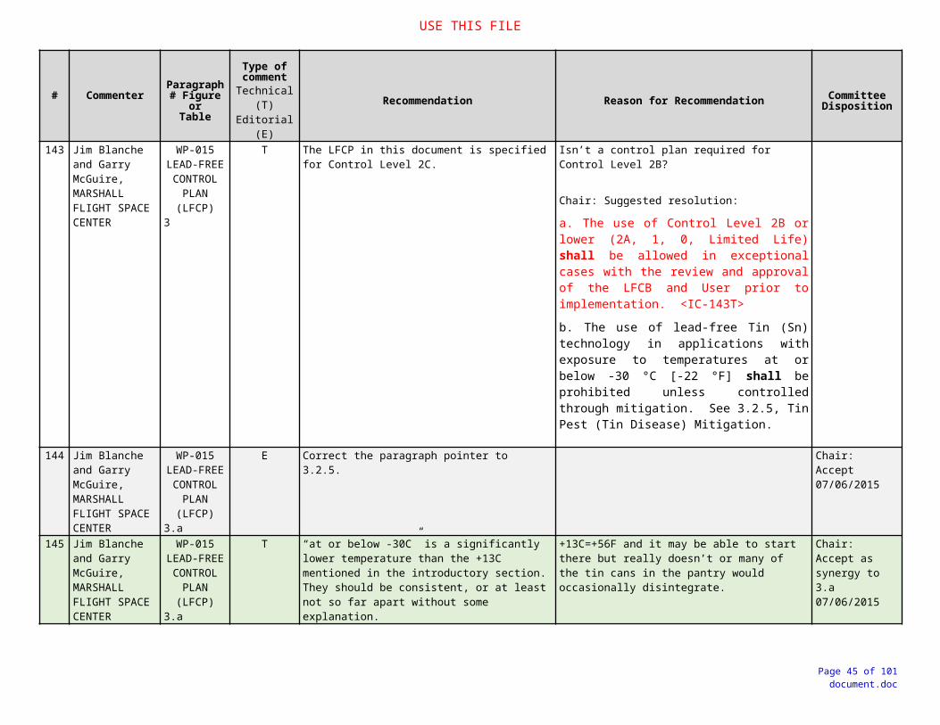
USE THIS FILE
# Commenter Paragraph # Figure or
Table
Type of comment
Technical (T)Editorial (E)
Recommendation Reason for Recommendation Committee Disposition
183 Stefan Hanigk, Airbus
WP-0153.2.4.2
T STRIP AND RE-PLATE TERMINATIONSIf alternatives to tin plated parts cannot be obtained, it may be possible to remove the tin finish. This is normally considered a high risk when performed on electronic components; the ability to remove the tin plating from the affected surfaces and refinish these surfaces must be made based on a risk and cost analysis.Such processes should be reviewed to determine the potential for affecting the reliability of the original product (e.g., chemical attack on component materials). This method is currently not approved and should be carefully reviewed prior to any use as it is perceived to be very high risk.
High risk, but why not.In special cases, an available alternative.
184 Stefan Hanigk, Airbus
WP-0153.2.4.2.1
T Possible damage to parts can include package cracking or loss of hermeticity resulting from thermal shock, popcorning of plastic packages, solder bridging between leads on fine pitch packages, solder bridging between leads and component body and handling damage such as bent or non-coplanar leads, electrostatic discharge, etc.
At the end of the first paragraph add this sentence.
185 Stefan Hanigk, Airbus
WP-0153.2.4.2.3
T Reflowed /Fusing TinReflowed tin is a stress relieving process applied to the component before it is soldered to the board.Fusing tin plating shortly after plating mitigates whisker formation. Fusing is a reflowing operation usually done by dipping the tin-plated surfaces into a hot oil bath.
Annealed TinAnnealing after plating has become a widely accepted whisker mitigation technique. Annealing at 150°C for 1 hour within 1 hr of plating is an acceptable mitigation technique as long as the part is also conformal coated after soldering to the board. Annealing has been proven to reduce the maximum whisker length and the growth rate by relieving plating stresses; causing grain growth increasing grain sizes and also forming a uniform intermetallic layer (IMC) of Cu6Sn5 over Cu3Sn which slows further intermetallic growth.
Two available alternatives.
Page 45 of 66document.doc

USE THIS FILE
# Commenter Paragraph # Figure or
Table
Type of comment
Technical (T)Editorial (E)
Recommendation Reason for Recommendation Committee Disposition
186 Stefan Hanigk, Airbus
WP-0153.2.4.2.4
T & E Conformal CoatingConformal coating or foam encapsulation over the whisker prone surface can significantly reduce the risk of electrical short circuits caused by whiskers. The effectiveness of this approach appears to be specific to the material types used and the environment. Publicly available data does not support conformal coating to be a cure for whisker growth. However, it does add an insulation barrier that may prevent shorting should long whisker growth occur.
Delete:External surfaces, platings, metallization, etc., with a lead-free Tin (Sn) finish shall be fully coated with conformal coating with a total cured finish thickness of not less than 100 μm [0.004 in] for silicone (SR) and urethane (UR), and not less than 50 μm [0.002 in] for paraxylene coatings. Total cured finish thicknesses specified shall take precedence over requirements imposed by J-STD-001(SPACE) [Table 10-1], or other user-approved conformal coating / polymeric standard.
New (3):Total cured finish thicknesses specified shall take precedence over requirements imposed by J-STD-001(SPACE) [Table 10-1], or other user-approved conformal coating / polymeric standard.
New (4) Using a combination of two different coatings parylene under either urethane or acrylic can be used, e.g. for repair.
Add this sentence in the beginning of the chapter.
The finish thicknesses are specified in point d. (1) and (2).
The LFCP overruled the IPC-J-STD-001x for lead-free surfaces.
For repair activities.
Page 46 of 66document.doc

USE THIS FILE
# Commenter Paragraph # Figure or
Table
Type of comment
Technical (T)Editorial (E)
Recommendation Reason for Recommendation Committee Disposition
187 Stefan Hanigk, Airbus
WP-0153.2.6
T REPAIR, REWORK, MAINTENANCE AND SUPPORTAll data and information required to conduct repair and rework shall be made available to those responsible for repair, rework, maintenance and support. All repair or rework must conform to the requirements of the drawing, items list and any referenced manufacturing documents. At the time of writing there are no PCB assemblies containing lead free solder, the approved repair/rework process is to use a tin/lead solder to solder all components, irrespective of whether the components contain lead or not. Refer to the PCB assembly documentation (e.g. drawing, bill of material, etc.) to determine whether to apply conformal coating.
A very important point that should definitely be included.
Page 47 of 66document.doc

USE THIS FILE
# Commenter Paragraph # Figure or
Table
Type of comment
Technical (T)Editorial (E)
Recommendation Reason for Recommendation Committee Disposition
188 Dave Hillman, Rockwell Collins
WP-016 Technical The 620 committee should either: (1) needs to move this document into the 620 Handbook with significant reformatting or (2) refer this white paper to the IPC JSTD 001/610 committees action/implementation and have it removed from inclusion in the 620 specification
Per the IPC Committee Chairman’s Handbook:
“7.3 Technical Reports, Technical Papers and White Papers
There will be times when your committee feels there is a need for published data about a specific area of technology which is either not addressed or current with the times. These reports can fill a need found during the development of a standard or publication or may come from a request by someone or a group of people in the industry. Many technical reports and technical papers are a result of round robin testing programs. These reports and papers can follow a similar format to the IPC Standardization Procedures, but they do not have to meet the procedures. To assure relevance, these reports should go through some level of peer review by a committee or group of SMEs. The final report or paper will be submitted to the TAEC for review and approval. “
The current WP-016 is not a white paper per the CC Handbook definition. The WP-016 is written as an actionable specification addressing a technical topic that is not exclusive to the 620 specification. The working paper could be tailored to reflect FOD topics specific to the 620 specification and included in the 620 specification as an actionable appendix. Alternatively, since the working paper does cover FOD at a high level, the working paper could be incorporated into the IPC JSTD 001/610 specifications either in the body of those documents or as an actionable appendix.
189 Barrie Dunn, School of Engineering, University of Portsmouth, UK
WP-016 FOREIGN OBJECT DEBRIS (FOD) CONTROL
E No specific comments, but am undecided if it is more convenient to include all these requirements into J-STD 001.
See recommendation
Page 48 of 66document.doc

USE THIS FILE
# Commenter Paragraph # Figure or
Table
Type of comment
Technical (T)Editorial (E)
Recommendation Reason for Recommendation Committee Disposition
190 Jim Blanche and Garry McGuire, MARSHALL FLIGHT SPACE CENTER
WP-016 FOREIGN OBJECT DEBRIS (FOD) CONTROL 1.2
T 2nd paragraph - add to the end of the 2nd sentence: when a FOD Control Plan is required by the User.
Unlike the other three white papers we are reviewing as part of this exercise, a FOD control plan is not imposed as a requirement so we should not require prior User approval of a plan that isn’t contractually imposed.
191 Jim Blanche and Garry McGuire, MARSHALL FLIGHT SPACE CENTER
WP-016 FOREIGN OBJECT DEBRIS (FOD) CONTROL 1.3.1
(1.5.1.a)
T Second sentence - From: When this standard is contractually invoked, the applicable requirements of this standard shall be imposed on all applicable subcontracts, assembly drawing(s), documentation and purchase orders
To: When the requirements of this document are contractually invoked, the applicable requirements of this document shall be imposed on all applicable subcontracts, assembly drawing(s), documentation and purchase orders
This is a White Paper and not a standard. If it is to be called a standard its title should be changed.
Chair: OBE 05/29/2015 synergy to WP-013, WP-014, WP-015
192 Jim Blanche and Garry McGuire, MARSHALL FLIGHT SPACE CENTER
WP-016 FOREIGN OBJECT DEBRIS (FOD) CONTROL 1.3.1
(1.5.1)
T Delete. A white paper cannot be (or at least definitely should not) be contractually imposed. There are no requirements in 001 or 620 to have a FOD Control Plan.
Chair: 1. There is a requirement for control of FOD in J-STD-001.2. There is a requirement for a FOD Control Plan in IPC-D-620.
Chair: OBE 05/29/2015 synergy to WP-013, WP-014, WP-015
193 Jim Blanche and Garry McGuire, MARSHALL FLIGHT SPACE CENTER
WP-016 FOREIGN OBJECT DEBRIS (FOD) CONTROL 1.3.2
(1.4)
T Delete. The references provided are not authority for a FOD control plan. Although they discuss FOD, they do not invoke a requirement for a plan.
Chair:There is a requirement for a FOD Control Plan in IPC-D-620.
Page 49 of 66document.doc

USE THIS FILE
# Commenter Paragraph # Figure or
Table
Type of comment
Technical (T)Editorial (E)
Recommendation Reason for Recommendation Committee Disposition
194 Jim Blanche and Garry McGuire, MARSHALL FLIGHT SPACE CENTER
WP-016 FOREIGN OBJECT DEBRIS (FOD) CONTROL 1.4
(1.6)
T Delete fANDSwitch c with d
Verbal correspondence is never accepted in conflict resolutions. If it isn’t in writing, it didn’t happen.ANDAs a white paper, it’s hard to defend that it would have precedence over a published IPC standard.
Chair: This is standard boiler-plate language and is included in WP-013, WP-014, and WP-015 (of which no comments were received for this specific requirement).
OBE by resolution of <IC-240T>
<IC-240T> Accept – delete (f) 06/23/2015
195 Jim Blanche and Garry McGuire, MARSHALL FLIGHT SPACE CENTER
WP-016 FOREIGN OBJECT DEBRIS (FOD) CONTROL 1.7
T Delete a. thru d. The lead-in sentence covers all 4 of these items.
Chair: This is standard boiler-plate language and is included in WP-013, WP-014, and WP-015 (of which no comments were received for this specific requirement).
196 Jim Blanche and Garry McGuire, MARSHALL FLIGHT SPACE CENTER
WP-016 FOREIGN OBJECT DEBRIS (FOD) CONTROL 3
T 2nd paragraph: Delete. As mentioned previously, there is no requirement for a FOD Control Plan unless a User specifically requires one. This paragraph reads as if it is using this white paper as justification for its existence.Alternatively, start the paragraph with “When required”.
Chair: See draft for possible resolution options.197 Jim Blanche and
Garry McGuire, MARSHALL FLIGHT SPACE CENTER
WP-016 FOREIGN OBJECT DEBRIS (FOD) CONTROL 3.1.d
E Change Figure reference to 1-1. Chair: Accept / mod. 05/29/2015
198 Larry Joy, Amptech, Inc.
WP-016 FOREIGN OBJECT DEBRIS (FOD) CONTROL 3.1d.
E The sentence refers to “Figure 2-1”. There is no Figure 2-1, the only figure in the document is “Figure F-1”.
Editing error. Chair: Accept / mod. 05/29/2015
Page 50 of 66document.doc

USE THIS FILE
# Commenter Paragraph # Figure or
Table
Type of comment
Technical (T)Editorial (E)
Recommendation Reason for Recommendation Committee Disposition
199 Jim Blanche and Garry McGuire, MARSHALL FLIGHT SPACE CENTER
WP-016 FOREIGN OBJECT DEBRIS (FOD) CONTROL 3.2
T Delete d. Grounds and other facility areas / surfaces over which FOD-sensitive hardware are transported shall be maintained free of FOD.
Grounds do not fit into 1.3 Applicability: “The requirements of this document apply to all work areas where both critical and complex work is performed; and, to operations involved with designing, developing, manufacturing, assembling, testing, operating, repairing, modifying, refurbishing, and maintaining Class 3 (or higher) hardware.”
FOD sensitive hardware should be in protective packaging while being transported. Keeping the grounds clear of FOD would seem to be an impossible task.
200 Jim Blanche and Garry McGuire, MARSHALL FLIGHT SPACE CENTER
WP-016 FOREIGN OBJECT DEBRIS (FOD) CONTROL 3.5
T FOD Awareness and Prevention Training - delete b. and e. and if necessary identify them in the second paragraph.
The bullets that address what training shall include mix who should be trained with what shall be taught. The second paragraph identifies who should have the training
Chair: See draft for proposed resolution.
201 Jim Blanche and Garry McGuire, MARSHALL FLIGHT SPACE CENTER
WP-016 FOREIGN OBJECT DEBRIS (FOD) CONTROL 3.7
T From: When FOD results in damage or suspected damage, the FOD Focal Point shall lead an investigation into the incident and identify corrective action as part of the overall FOD trending and measurement assessment.
To: When FOD results in damage or suspected damage, the FOD Focal Point shall lead an investigation into the incident and identify corrective action and recurrence control as part of the overall FOD trending and measurement assessment.
Recurrence control is as essential as corrective action and is included in the note but not in the requirements.
Chair: See draft for proposed resolution.
202 Larry Joy, Amptech, Inc.
WP-016 FOREIGN OBJECT DEBRIS (FOD) CONTROL 3.8a.
E Reference is made to “Figure 1” in two places. There is only a “Figure F-1” in the document.
Editing error. Chair: OBE
Page 51 of 66document.doc

USE THIS FILE
# Commenter Paragraph # Figure or
Table
Type of comment
Technical (T)Editorial (E)
Recommendation Reason for Recommendation Committee Disposition
203 Jim Blanche and Garry McGuire, MARSHALL FLIGHT SPACE CENTER
WP-016 FOREIGN OBJECT DEBRIS (FOD) CONTROL 4.1
T Cleanliness Level – Identify the cleanliness levels in this document somewhere.
To avoid having to go to another document to identify them.
Chair: The use of the phrase “Cleanliness Level” opens a can of worms, as “Cleanliness” and “FOD Control” are often separate but overlapping issues. It is not the intention of this document to serve as a “Contamination Control” document.
Suggestions:1. Delete all references “specified cleanliness level”2. Add the definition in section 4 as detailed in mark-up and hope no one notices.3. Add the definition in section 4, embrace the chaos, and insert a new section 3.2 as detailed in mark up.
204205206207208209210
211 Jim Blanche & Garry McGuire - MSFC
1.3 T Performance/Product Classification Change second paragraph to: It is the responsibility of the contract to specify the performance class required, whether compliance to any of the A through G Appendices is required, and indicate any exceptions to specific parameters where appropriate.
A standard cannot impose requirements on a contract.
Chair: Suggested resolution:The User is responsible for defining the performance class required, whether compliance to any of the A through C Appendices is required, and to indicate any exceptions to specific parameters where appropriate.
Accept / modify 06/16/15
Page 52 of 66document.doc

USE THIS FILE
# Commenter Paragraph # Figure or
Table
Type of comment
Technical (T)Editorial (E)
Recommendation Reason for Recommendation Committee Disposition
212 Jim Blanche & Garry McGuire - MSFC
1.3 Class 1 E Change from: Includes consumer products, as well as general military hardware suitable for applications where cosmetic imperfections are not important and the major requirement is function of the completed assemblyTo; Includes products for applications where the major requirement is the function of the completed assembly
The design standard should define the product classes the same way as the fabrication/acceptance standard. The proposed paragraph is what is used for the definition of Class 1 products in both A-620B and J-STD-001F.
Chair: Accept, synergy to J-STD-001F and IPC/WHMA-A-620B. 06/09/2015
213 Jim Blanche & Garry McGuire - MSFC
1.3 Space E Insert a new paragraph above the existing statement:The same expectations as Class 3 with extra considerations for unique materials requirements and more extreme operational environments, e.g., vibration and thermal cycling.
Class 1-3 give a good idea on what to expect if you choose a particular class. The Space paragraph should provide similar information.
Chair: Accept 06/09/2015
214 Jim Blanche & Garry McGuire - MSFC
1.4.1 T Requirement Format (A/N)
Delete the example [N1N2N3]
There are not any requirements in this document that are not applicable to any of the three classes of hardware. This notation is saying a requirement would not be imposed on Class 1, 2 or 3 therefore it would not be a requirement.
Accept.06/16
215 Jim Blanche & Garry McGuire - MSFC
1.6 E Definition of Terms Reference to Section 10 should be Section 9.
Typo Chair: OBE <IC-06E> 06/01/2015
216 Jim Blanche & Garry McGuire - MSFC
1.9 E Appendices A-C In the second line change “which” to “with”
Typo Chair: OBE by change implemented by <IC-07E>. 06/01/2015>
217 Jim Blanche & Garry McGuire - MSFC
1.9 T Delete the current “c” Either the appendices are invoked or they’re not. If they are not invoked why would AABUS be necessary and if they are invoked there is no need for AABUS.
Withdrawn06/16
218 Jim Blanche & Garry McGuire - MSFC
1.10 E 3rd paragraph: Change “DESIGNER” to “Designer”. Use the proper noun form as defined in 1.2…no need to shout it.
Chair: Accept 06/01/2015
219 Schuyler Williams, Lockheed Martin
Section 2.1, Page 12 T
ADD: A wire splice to the specification.
AIA/NAS NAS1744................Splice, Conductor, Solder Style, Hot Air or Infrared, Shrinkable, Insulated, Immersion Resistant
Aerospace specifications section only includes a shield splice. A shield splice is a larger component for shields and multiple wires. The specification should include a small high performance splice for small gauge single wire splices.
Chair: See draft for proposed resolution.
A/M Referenced 1747, which includes 1744-174606/16
Page 53 of 66document.doc

USE THIS FILE
# Commenter Paragraph # Figure or
Table
Type of comment
Technical (T)Editorial (E)
Recommendation Reason for Recommendation Committee Disposition
220 Jim Blanche & Garry McGuire - MSFC
3.2.2.2.e E Delete “and cable installations” Seems out of scope for the rest of the sentence. Chair: Accept 06/01/2015
221 Jim Blanche & Garry McGuire - MSFC
4.5 T 4.5 FOREIGN OBJECT DEBRIS (FOD) CONTROL PLAN The first 4.5 FOD Control Plan has a Shall with no applicability identified.Start the first sentence with, “When a Foreign Object Debris Prevention Program is required it shall [A1A2A3] be established for the ………”
Do not push designers to mandate FOD control plans if they’re not necessary.
Chair: See draft for proposed resolution.
4.5 FOREIGN OBJECT DEBRIS (FOD) CONTROL PLANWhen a Foreign Object Debris (FOD) Prevention Program (a.k.a.: FOD Control Plan) is required, it shall [A1A2A3] be established for the design, development, manufacturing, assembly, repair, processing, testing, maintenance, operation, and check out of cable and wiring harness assemblies to prevent immediate and latent damage, and to ensure compliance to the specified cleanliness level. See WP-016, Foreign Object Debris (FOD) Control Plan for technical guidance and requirements.
Accept 06/16
222 Jim Blanche & Garry McGuire - MSFC
4.5 E 4.5 Prohibited / Restricted Usage Parts, Materials, Processes (PMP) The second 4.5 and its subparagraphs need renumbering
Chair: OBE 06/01/2015
223 Jim Blanche & Garry McGuire - MSFC
4.5.5(4.6.5)
T Crimping Of Solder-Tinned and Solid Conductors –Delete first paragraph
These are all D1D2D3 in 620 so there is a conflict. The 2nd paragraph has the meat for when it must be done for whatever reason.
Accept as modified by 224T/E
224 Jim Blanche & Garry McGuire - MSFC
4.5.5(4.6.5)
T/E Crimping Of Solder-Tinned and Solid Conductors -Second paragraph From: Designs requiring any of the following shall [A1A2A3] detail the process and acceptance criteria on the engineering documentation and prior approval from the User:
To: Designs requiring any of the following shall [A1A2A3] detail the process and acceptance criteria on the engineering documentation and have prior approval from the User:
It appears that it is requiring that these designs will detail prior approval from the User rather than have prior approval from the User and detail the process and acceptance criteria.
Chair: See draft for proposed resolution.
Accept06/16
225 Jim Blanche & Garry McGuire - MSFC
4.5.6(4.6.6)
E Cuprous Oxide Corrosion Reference WP-013
Per committee agreement. It is referenced in 4.6.2.c.3 but it should be referenced here as well.
Chair: OBE06/01/2015
Page 54 of 66document.doc

USE THIS FILE
# Commenter Paragraph # Figure or
Table
Type of comment
Technical (T)Editorial (E)
Recommendation Reason for Recommendation Committee Disposition
226 Jim Blanche & Garry McGuire - MSFC
4.5.11(4.6.11)
E Replace the Figure with a picture that does not show the split lockwasher.
It is out of scope for this paragraph and may lead the reader to believe it is prohibited.
Chair: Please see 06/01/15 draft to see if rewording caused by <IC-23E> addresses the concern.
Withdrawn06/16/15
227 Jim Blanche & Garry McGuire - MSFC
4.5.11(4.6.11)
E The figure for this section is below the title for the following paragraph
Chair: This is a typesetting issue.
228 Jim Blanche & Garry McGuire - MSFC
4.5.14(4.6.14)
T Micro-D Connectors Expand on the rationale
This rationale does not justify not using them. What are the weaknesses or failure modes other than they may not be good enough?
Chair: Please see 06/01/15 draft to see if rewording addresses the concern.
Micro-D size connectors shall not [N1N2A3] be used in Category IV (EED), life-critical, and/or extreme operational environment (high vibration, thermal cycling, mechanical shock) designs or products, unless provided with (a) hood “clamping” mechanisms surrounding the female contact engagement tine(s) or a reverse gender “bulged wire twist” pin design, (b) positive locking / retention devices, and (c) prior approval by the User.Rationale: Connector contact systems having two (2) points of contact engagement, or less; that do not utilize a military style hood “clamping” mechanism to support female contact engagement tines; and, that do not incorporate a positive locking / retention device may not be suitable for use in high vibration and/or thermal cycling environments where signal integrity and EMI immunity are critical to performance and reliability of critical circuits.
Accept / modify 06/16/15
229 Jim Blanche & Garry McGuire - MSFC
4.5.18(4.6.18)
T Splices Don’t see a prohibition for splices in pyrotechnic cables.
Is this now allowed? It is prohibited in Class 3/A, Table A1,4.5.18.g (New), why not in Class 3?
Chair: This issue was moved to Appendix A per APEX15.
A/M 06/16/15
Page 55 of 66document.doc
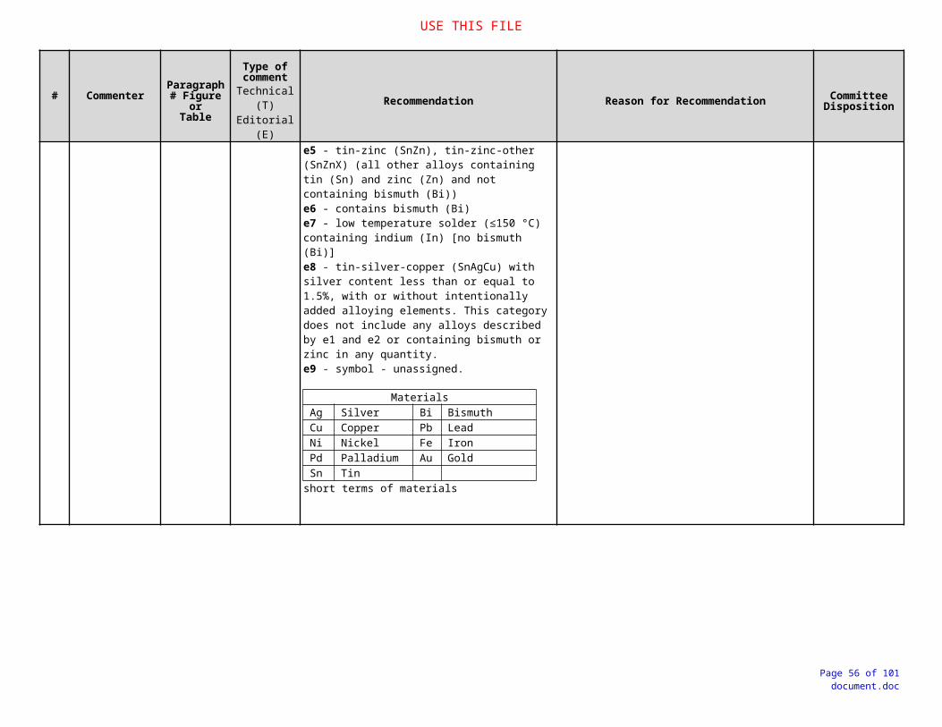
USE THIS FILE
# Commenter Paragraph # Figure or
Table
Type of comment
Technical (T)Editorial (E)
Recommendation Reason for Recommendation Committee Disposition
230 Jim Blanche & Garry McGuire - MSFC
4.7.1.a.3(4.8.1.a.3)
T Mating Provisions From: Selection of alternative polarization, keying, colors, electrical interlock / confidence loop circuits, and/or clocking of adjacent, similar connectors only if this requirement cannot be met with either method (1) or (2) above.
To: Selection of alternative polarization, keying, colors, electrical interlock / confidence loop circuits, and/or clocking of adjacent, similar connectors.
This is an unnecessary prohibition
Chair: Please see draft to see if rewording addresses the concern.
(3) Selection of alternative polarization, keying, colors, electrical interlock / confidence loop circuits, and/or clocking of adjacent, similar connectors.
Accept 06/16/2015
231 Jim Blanche & Garry McGuire - MSFC
4.7.1.b(4.8.1.b)
T Mating Provisions
Change shall to should.
“When practical” can be in the eye of the inspector and difficult to enforce. The application of the system the cable will be used in may dictate using one of these control techniques.
Chair: Please see draft to see if rewording addresses the concern.
b. The following control techniques should only be employed when the above physical design features are not practical:
Accept as modified06/16
232 Jim Blanche & Garry McGuire - MSFC
5.2 T Corona Suppression – Second sentence from:Test(s) or analysis shall [A1A2A3] be performed to demonstrate that the cable and wiring harness assemblies will remain protected for the design service life of the hardware (See 3.1.1.6).To: Test(s) or analysis shall [A1A2A3] be performed to demonstrate that that detrimental corona discharge will not occur under any operating conditions and the cable and wiring harness assemblies will remain protected for the design service life of the hardware (See 3.1.1.6).
How are cable and harness assemblies designed such that detrimental corona discharge will not occur under any operating conditions? This is a design document. Possibly provide some direction on how to meet the requirement such as is done in 5.4.1 EMP Environment
Chair: Please see draft to see if rewording addresses the concern.
Accept as modified06/16
Page 56 of 66document.doc

USE THIS FILE
# Commenter Paragraph # Figure or
Table
Type of comment
Technical (T)Editorial (E)
Recommendation Reason for Recommendation Committee Disposition
233 Schuyler Williams, Lockheed Martin
Section 6.7.b, Page 44
T
Define proper design requirements for cable branch strain relief.
Suggested Rewording….
WAS:b. Breakout Support. Breakouts shall [A1A2A3] be long enough to provide proper support at installation. Breakouts shall [A1A2A3] be secured by connector backshells or clamps as close to the connector as practical but shall not [A1A2A3] violate stress relief.NOW:b. Breakout Support. Breakouts shall [A1A2A3] be long enough to provide proper support at installation. Breakouts shall [A1A2A3] be mechanically supported at the cable branch joints. Cable branch joints shall [A1A2A3] use heat shrinkable boots, potting, mechanical wire routing organizers, or other appropriate methods to strain relief each individual branched joint. Strain relief shall [A1A2A3] be a minimum of two diameters in length for each cable branch. The diameter used to determine strain relief distance shall be based on the diameter of the largest cable branch entering into the cable branch joint transition area.
Example:
Protection and Support section does not adequately define proper or adequate cable branch joint strain relief support methods.
Chair: Please see draft to see if rewording addresses the concern.
Accept / modified 06/23/2015
Page 57 of 66document.doc

USE THIS FILE
# Commenter Paragraph # Figure or
Table
Type of comment
Technical (T)Editorial (E)
Recommendation Reason for Recommendation Committee Disposition
234 Jim Blanche & Garry McGuire - MSFC
6.7.a T/EE (Chair)
From: Main Bundle Support. The main bundle shall [A1A2A3] be secured within two harness diameters (2d) of the emergence of a breakout from the main bundle, within two harness diameters (2d) following the emergence of a breakout, and at intervals not to exceed 61 cm [24 in]. To: Main Bundle Support. The main bundle shall [A1A2A3] be secured within two harness diameters (2d) ahead of the emergence of a breakout from the main bundle, within two harness diameters (2d) following the emergence of a breakout, and at intervals not to exceed 61 cm [24 in].
This is confusing as stated and can be interpreted to be repeating itself. A one word addition eliminates ambiguity.
Chair: accept as editorial. 05/01/2015
235 Jim Blanche & Garry McGuire - MSFC
6.8 T Etching Fluoropolymer-Insulated Electrical WireChange the first shall [N1N2A3] to [A1A2A3]
If the design requires mechanical bond or environmental seal etching is required regardless of the Class of the cable.
Chair: See draft for proposed resolution.
Designs requiring the development of a mechanical bond and/or environmental seal to fluoropolymer-insulated / coated electrical wire or cable shall [A1A2A3] require the portion of the wire or cable to be wetted to be etched prior to application of adhesive / polymer.
Accept / modify 06/23/2015
236 Jim Blanche & Garry McGuire - MSFC
Table A1, 6.9
T Delete MSFC does NOT do this, nor do we agree that it is necessary.
Accept 06/23/2015
237 Jim Blanche & Garry McGuire - MSFC
Table A1, 7.5
T This should be moved as a 7.5 to the body of the document as a shall [A1A2A3[.
Why are time critical or limited life items not tracked for anything but Military/Space Applications Hardware?These should be very important for Class 3 hardware at the very least.
Chair: This section used to be in the body of the document and was moved to Appendix A, because the committee decided that it should only be applicable to Space and Military.
Accept / modify06/23/2015
Deleted from Appendix A and moved to 7.5 in body, with modifications
Page 58 of 66document.doc

USE THIS FILE
# Commenter Paragraph # Figure or
Table
Type of comment
Technical (T)Editorial (E)
Recommendation Reason for Recommendation Committee Disposition
238 Stefan Hanigk, Airbus Defence and Space
WP-013; "Red-Plague-Control-Plan"
Technical Background
T It is observed that the electrically conductive path has been degraded, in particular with thin wires.
The color of the corrosion by-product (cuprous oxide crystals) may vary depending on the amount of oxygen available, but is commonly noted as a red/reddish-brown discoloration on the silver plating surface.
At the end of the first paragraph add this sentence.
Chair: See proposed resolution in draft.
Accept 06/23/2015
239 Stefan Hanigk, Airbus Defence and Space
WP-0131.4
T Rewording from:"Authority"To:"Responsibilities" in headline and text.IPC J-STD-001 is now version "F" and "FS".
Clarification
Chair: This requirement was initially OBE by IC-77E.
The authority for invoking the requirements of this document derives from the Red Plague Control requirements in the Space Addendums to IPC/WHMA-A-620, “Requirements and Acceptance for Cable and Wire Harness Assemblies”, and IPC J-STD-001, “Requirements for Soldered Electrical and Electronic Assemblies”.
Accept / modify: add “… invoking the requirements of …”. 06/23/2015
240 Stefan Hanigk, Airbus Defence and Space
WP-0131.6.f
T Delete f Verbal correspondence or e-mails are not contractual
Chair: This requirement is directed towards resolution of conflicts between documents. While verbal correspondence is not recommended (and risky) it is used to resolve conflicts. See proposed resolution in draft.
Chair: Disposition of this comment will be global to all documents in this review set.
Accept – delete (f) 06/23/2015
241 Stefan Hanigk, Airbus Defence and Space
WP-0133.2.1.1
E Rewording from:"Micrometer"To:"SCC/SCA & SCU Cable"
Chair: Accept 06/09/2015
242 Stefan Hanigk, Airbus Defence and Space
WP-0133.2.1.2
E Rewording from:"Micrometer"To:"SCC1/SCA1 Cable"
Chair: Accept 06/09/2015
Page 59 of 66document.doc
USE THIS FILE
# Commenter Paragraph # Figure or
Table
Type of comment
Technical (T)Editorial (E)
Recommendation Reason for Recommendation Committee Disposition
243 Stefan Hanigk, Airbus Defence and Space
WP-0133.2.3 a
(3.3.a)
T Can be deleted. These requirements are already in the IPC-J-STD-001 and IPC / WHMA-A-620 available.
Chair: The requirements in 3.2.3 are wire acceptance specifications specific to detection and control of Red Plague.
Action: Bob
Accept 06/30/15
244 Stefan Hanigk, Airbus Defence and Space
WP-0133.2.3 b
(3.3.b)
T Can be deleted This is a recommendation and not a mandatory requirement. The minimum requirements are already defined in IPC-J-STD-001 and IPC / WHMA-A-620.
Chair: The requirements in 3.2.3 are wire acceptance specifications specific to detection and control of Red Plague.
Accept / modify 06/30/15
245 Stefan Hanigk, Airbus Defence and Space
WP-0133.2.3 c
T Can be deleted If requirements in the production documentation from the manufacturer, is present must be complied with these requirements in general.
Chair: The requirements in 3.2.3 are wire acceptance specifications specific to detection and control of Red Plague.
See recommended solution in draft.
Accept / modify 06/30/15
246 Stefan Hanigk, Airbus Defence and Space
WP-0133.3. a(moved to 3.2.3)
T Can be deleted or rewording to:"All wire and cable shall have full lot traceability and manufacturer’s test reports according IPC-J-STD-001 and IPC / WHMA-A-620 requirements.
The traceability is always addressed in IPC-J-STD-001 and IPC / WHMA-A-620.
Chair: Lot traceability and manufacturer test reports (component level) are not addressed in either document.
Accept / modify 06/30/15
247 Stefan Hanigk, Airbus Defence and Space
WP-0133.3 b
T Rewording from:"Test reports, and all tested and untested micro-section analysis coupons, shall be delivered to the User as part of the procurement."To:"When required by the procurement specification, Test reports, and all tested and untested micro-section analysis coupons, shall be delivered to the User as part of the procurement."
Chair: Requested change to (b) nullifies intent of (a), which was to require lot traceability and test reports.
Accept / modify 06/30/15
Page 60 of 66document.doc

USE THIS FILE
# Commenter Paragraph # Figure or
Table
Type of comment
Technical (T)Editorial (E)
Recommendation Reason for Recommendation Committee Disposition
248 Stefan Hanigk, Airbus Defence and Space
WP-0133.6.1
T Further requirements on the IPC-J-STD-001 and IPC / WHMA-A-620 beyond as a recommendation.
There may be no further claim on the requirements of IPC-J-STD-001 and IPC / WHMA-A-620, see also 1.4.
Chair: The requirements in this document are specific to control of Red Plague.
Not accept. Once WP-013 is published, the requirements in -001 and -620 for red plague control will be reduced to a pointer to WP-013.06/30/15
249 Stefan Hanigk, Airbus Defence and Space
WP-0133.7.1 a (1) to (3)
T Rewording:a. One (1) test specimen, approximately 30 cm in length (including the capped end), to perform the required inspection(s) shall be required. Original reel/spool only on the outer end:(1) From each end of each continuous, unspliced length reel or spool. (2) From each end of reeled or spooled wire sections (non-continuous lengths).(3) From each end of coiled lengths.Note: The last few meters of reel/spool are not to use it.
In points 1 to 3 are described tests are suitable for a test after cutting to the length of cables. This test is not for cable on reel suitable. No one is at the receiving inspection winding / rewinding several 100 m cable.
<IC-249T> Change (a) as follows:Test Specimen. One (1) test specimen, approximately
30 cm [12 in] in length (including the capped end), to perform the required inspection(s) shall be required: (1) From the outer end of each continuous, unspliced length reel or spool.(2) From the outer end of each reeled or spooled wire section (non-continuous lengths).(3) From each end of coiled lengths.
Note: It is not recommended that the last remaining 100 cm (39.4 in) length of wire on either a continuous, unspliced length reel or spool, or a reeled or spooled wire section (non-continuous lengths) be used for assembly build.
Accept / modify 06/30/15
250 Stefan Hanigk, Airbus Defence and Space
WP-0133.7.2
T Rewording:…. shall be stored per 4.1 - Shipping and Storage….to….are in accordance with 4. Capping to be stored….
4.1 Shipping and Storage is an invalid link.
Chair: Correct reference is 3.6.1 - Packaging - Shipping and Storage
Chair: OBE by previous edits.06/10/2015
250a
Jim Blanche & Garry McGuire - MSFC
WP-0133.7.2
T Change pointer from 4.1 to 3.6.1 4.1 does not address Shipping and Storage Chair: OBE by previous edits.06/10/2015
Page 61 of 66document.doc

USE THIS FILE
# Commenter Paragraph # Figure or
Table
Type of comment
Technical (T)Editorial (E)
Recommendation Reason for Recommendation Committee Disposition
251 Stefan Hanigk, Airbus Defence and Space
WP-0133.7.3
T Rewording:See 3.9 - Non-Conformance
Add:Missing humidity indicator card leads also to the result rejection and segregation.
7. is an invalid link
Without HIC there are no clear information available.
See recommended solution in draft.
Accept 06/30/15
252 Stefan Hanigk, Airbus Defence and Space
WP-0133.8.3
T Add:The minimum permitted bending radius are described in the IPC-J-STD-001F and IPC / WHMA-A-620B.
Clear definitions
See recommended solution in draft.
Accept / modify 06/30/15
253 Stefan Hanigk, Airbus Defence and Space
WP-013 & WP-015
T Move WP-013 and WP-015 to the IPC AJ 820. The demands on the LFCP and RPCP are described in detail in the Space Addendum´s of the IPC-J-STD-001FS and IPC / WHMA-A-620BS. The documents WP-013 and WP-015 are therefore content in the IPC-AJ820 better, for example after the topic Wisker. The documents WP-013 and WP-015 only give more general guidance in addition to the demands of the standards 001 and 620.
Chair: WP-013 and WP-015 were specifically written to allow the corresponding requirements in J-STD-001xS and IPC/WHMA-A-620xS to be reduced to a single sentence similar to the paragraphs in IPC-D-620.
Additionally, both WP-013 and WP-015 are structured as templates for control plan documents, and not just technical information.
OBE by IPC staff decision to separate the WPs as individual documents. 06/30/15
Page 62 of 66document.doc

USE THIS FILE
# Commenter Paragraph # Figure or
Table
Type of comment
Technical (T)Editorial (E)
Recommendation Reason for Recommendation Committee Disposition
254 Jim Blanche and Garry McGuire, MARSHALL FLIGHT SPACE CENTER
WP-014 WHITE PLAGUE CONTROL PLAN 1.7
T First sentence from:All dimensions and tolerances, as well as other forms of measurement in this standard are expressed in SI (System International) units, with Imperial English equivalent dimensions provided in [brackets].
To:All dimensions and tolerances, as well as other forms of measurement in this standard are expressed in SI (System International) units, with Imperial English equivalent dimensions provided in [brackets] except as noted.
And add an f.f. Time values are expressed in hours, minutes and seconds.
Chair: This change is likely global to all of the WPs.
1.7 Measurement Units and Tolerances <IC-254T>All dimensions and tolerances, as well as other forms of measurement in this standard are expressed in SI (System International) units, with Imperial English equivalent dimensions provided in [brackets], except as noted. a. Linear dimensions and tolerances use
centimeters (cm) [inches (in)] as the main form of dimensional expression; millimeters (mm) [inches (in)] or micrometers (µm) [microinches (µin)] are used when the required precision makes the use of centimeters (cm) too cumbersome.
b. Temperature values are expressed in degrees Celsius (°C) [Fahrenheit (°F)].
c. Mass is expressed in grams (g) [ounces (oz)].d. Wire, wire harness, and cable diameters are
expressed in the non-dimensional unit (d), where a numerical dimension, such as 2d, is solely dependent on a physical attribute of the hardware (e.g.: wire gauge, harness diameter, etc.).
e. Time values are expressed in hours, minutes and seconds (hh:mm:ss).
f. For the purposes of determining conformance to this specification, all specified limits in this standard are absolute limits as defined in ASTM E29.
Accept 06/30/15
Waterfall to all documents as global change
255 Robert CookeNASA/ JSC
D-620, WP-(all)1.2
E Add (d) For military contracts, the User is considered the “Contracting Agency” or their designated “Contracting Agent”.
Add guidance for use by military contractors, in anticipation of J-STD-001(military). This would be a global change to all the documents in the suite.
Reject original addition. 06/30/2015 Inserted and modified definitions from J-STD-001F. This change is global to all documents.
256
Page 63 of 66document.doc

USE THIS FILE
S Hanigk Comment - Annex:Component Lead-Free Finishes
Base Material
Solderable Finish
Thru Hole parts (Typically Cu 7025, 194 etc. lead; excluding brass)
SMD Devices Low expansion alloys (FeNi, Alloy 42, Kovar™ etc. Typical CTE ±5ppm)
SMD Devices Ceramics, no lead frame (Resistors & Capacitors)
NiPdAuNiPdNiAuSn/Pb plating (>3% Pb)Gold Flash over CuSnAgCu (SAC Alloy)Ag (over Ni)Ag (over Cu) see also WP-013; Red Plague Control Plan
Sn (fused), no barrier layerHot dipped SnAgCuHot dipped SnAgMatte SnCu 150°C annealPlated SnAg (1.5 to 4% Ag)Sn over BrassBright Sn with Ni barrier layerSn over steel, Ag, Cu or Ni barrier
SnBi (2 to 4% Bi)Matte Sn with Ni barrier layer n/aMatte Sn with Ag barrier layerSn, 150°C anneal
AgPd (over Ni)Ag (over Ni)AgSnCuBright TinMatte SnCu, 150 anneal (2% Cu)Bright Tin with Ni barrier layer
Page 64 of 66document.doc

USE THIS FILE
Component Lead-Free FinishesBase Material
Solderable Finish
Thru Hole parts (Typically Cu 7025, 194 etc. lead; excluding brass)
SMD Devices Low expansion alloys (FeNi, Alloy 42, Kovar™ etc. Typical CTE ±5ppm)
SMD Devices Ceramics, no lead frame (Resistors & Capacitors)
Matte SnSemi Matte Sn
Table-a
Page 65 of 66document.doc

USE THIS FILE
Termination Finishes for Separable Connectors
Finish
Termination finish use only as a solderable finish
Terminal finish use as a separable interface for fine spacing applications.
Terminal finish use as a separable interface for large spacing applications
NiAuNiPdNiPdAuAg (over Ni)
Hot dipped SnAgCuReflowed SnHot Dipped SnHot Dipped SnCuMatte Sn w/Nickel underplateMatte Sn w/Silver underplate
Matte Sn - 150C annealMatte SnBi (2-4% Bi) w/Nickel UnderplateMatte SnAg (1.5 - 4% Ag) w/Nickel underplateSnCu w/Nickel underplate
Bright Tin w/nickel underplateMatte SNBi (2-4% Bi)Matte SnAg (1.5-4% Ag)Matte Sn (No underplate)Bright TinSnCu
Table-b
Page 66 of 66document.doc