Embed Size (px)
Citation preview

IRRInet–XL Remote Terminal Unit
Owner’s Manual
A
68P02962C86-O
@6802962C86@September, 2001
Commercial, Government andIndustrial Solutions Sector
i
Contents
CHAPTER 1 GENERAL DESCRIPTION .....................................................................................1-1 1.1 IRRInet-XL - RTU Wall Mount and Housing Options..........................................................1-1 1.2 RTU Models ..........................................................................................................................1-4 1.3 I/O & Communication Modules............................................................................................1-5 1.4 Power Supply and Backup Battery Options .......................................................................1-6
CHAPTER 2 INSTALLATION......................................................................................................2-1 2.1 Before Mounting the RTU ....................................................................................................2-1 2.2 Wall Mounting of RTU Without Housing Enclosure...........................................................2-2 2.3 Wall Mounting of RTU in NEMA4X Housing Enclosure .....................................................2-3 2.4 Wall Mounting of RTU with NEMA4 Housing Enclosure....................................................2-4 2.5 Electrical Connections.........................................................................................................2-5
2.5.1 Ground Connection...........................................................................................................2-5 2.5.2 Main Power Connections..................................................................................................2-6 2.5.3 Electrical Connections For 8 Ampere Power Supply .........................................................2-8 2.5.4 8 Ampere Power Supply Field Replaceable Parts...........................................................2-11 2.5.5 Electrical Connections for 45 VA Power Transformer .....................................................2-11 2.5.6 45 VA Transformer Field Replaceable Parts...................................................................2-14
2.6 Backup Battery Connections.............................................................................................2-14 2.6.1 5AH Backup Battery .......................................................................................................2-14 2.6.2 5AH Backup Battery Field Replaceable Parts .................................................................2-15 2.6.3 3AH Backup Battery .......................................................................................................2-16 2.6.4 3AH Backup Battery Field Replaceable Parts .................................................................2-16
2.7 Radio Connections.............................................................................................................2-17 2.7.1 Mobile Radio...................................................................................................................2-17 2.7.2 Mobile Radio Field Replaceable Parts ............................................................................2-18 2.7.3 Portable Radios ..............................................................................................................2-19 2.7.4 Portable Radio Field Replaceable Parts .........................................................................2-21
2.8 RTU Configuration Block Diagrams..................................................................................2-22 2.8.1 Basic Interconnection Block Diagram..............................................................................2-22 2.8.2 Connecting the RTU by Wire Line...................................................................................2-23 2.8.3 Connecting the RTU by Single Mobile Radio ..................................................................2-24 2.8.4 Connecting the RTU by Two Separate Mobile Radios ....................................................2-25
2.9 Installation of Plug-in Modules and Units.........................................................................2-26 2.10 Module Replacement........................................................................................................2-27
2.10.1 Removing the Power Supply Module ............................................................................2-27 2.10.2 Installing the Power Supply Module ..............................................................................2-27
2.11 Radio Antenna Placement ...............................................................................................2-28 2.12 IRRInet-XL Field Replaceable Parts ................................................................................2-29
ii
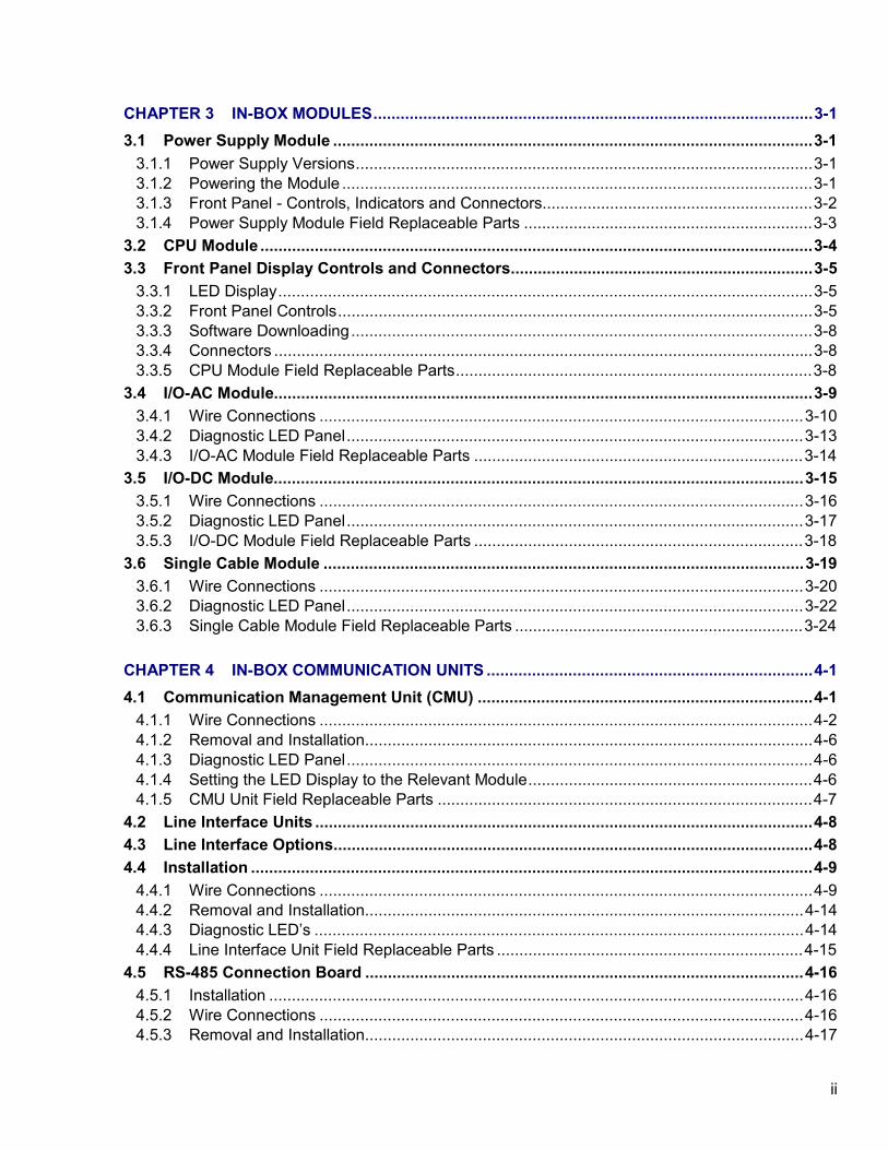
CHAPTER 3 IN-BOX MODULES.................................................................................................3-1 3.1 Power Supply Module ..........................................................................................................3-1
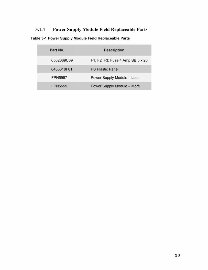
3.1.1 Power Supply Versions.....................................................................................................3-1 3.1.2 Powering the Module ........................................................................................................3-1 3.1.3 Front Panel - Controls, Indicators and Connectors............................................................3-2 3.1.4 Power Supply Module Field Replaceable Parts ................................................................3-3
3.2 CPU Module ..........................................................................................................................3-4 3.3 Front Panel Display Controls and Connectors...................................................................3-5
3.3.1 LED Display......................................................................................................................3-5 3.3.2 Front Panel Controls.........................................................................................................3-5 3.3.3 Software Downloading......................................................................................................3-8 3.3.4 Connectors .......................................................................................................................3-8 3.3.5 CPU Module Field Replaceable Parts...............................................................................3-8
3.4 I/O-AC Module.......................................................................................................................3-9 3.4.1 Wire Connections ...........................................................................................................3-10 3.4.2 Diagnostic LED Panel.....................................................................................................3-13 3.4.3 I/O-AC Module Field Replaceable Parts .........................................................................3-14
3.5 I/O-DC Module.....................................................................................................................3-15 3.5.1 Wire Connections ...........................................................................................................3-16 3.5.2 Diagnostic LED Panel.....................................................................................................3-17 3.5.3 I/O-DC Module Field Replaceable Parts .........................................................................3-18
3.6 Single Cable Module ..........................................................................................................3-19 3.6.1 Wire Connections ...........................................................................................................3-20 3.6.2 Diagnostic LED Panel.....................................................................................................3-22 3.6.3 Single Cable Module Field Replaceable Parts ................................................................3-24
CHAPTER 4 IN-BOX COMMUNICATION UNITS ........................................................................4-1 4.1 Communication Management Unit (CMU) ..........................................................................4-1
4.1.1 Wire Connections .............................................................................................................4-2 4.1.2 Removal and Installation...................................................................................................4-6 4.1.3 Diagnostic LED Panel.......................................................................................................4-6 4.1.4 Setting the LED Display to the Relevant Module...............................................................4-6 4.1.5 CMU Unit Field Replaceable Parts ...................................................................................4-7
4.2 Line Interface Units ..............................................................................................................4-8 4.3 Line Interface Options..........................................................................................................4-8 4.4 Installation ............................................................................................................................4-9
4.4.1 Wire Connections .............................................................................................................4-9 4.4.2 Removal and Installation.................................................................................................4-14 4.4.3 Diagnostic LED’s ............................................................................................................4-14 4.4.4 Line Interface Unit Field Replaceable Parts ....................................................................4-15
4.5 RS-485 Connection Board .................................................................................................4-16 4.5.1 Installation ......................................................................................................................4-16 4.5.2 Wire Connections ...........................................................................................................4-16 4.5.3 Removal and Installation.................................................................................................4-17
iii
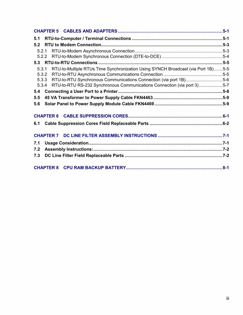
CHAPTER 5 CABLES AND ADAPTERS ....................................................................................5-1 5.1 RTU-to-Computer / Terminal Connections .........................................................................5-1 5.2 RTU to Modem Connection..................................................................................................5-3
5.2.1 RTU-to-Modem Asynchronous Connection.......................................................................5-3 5.2.2 RTU-to-Modem Synchronous Connection (DTE-to-DCE) .................................................5-4
5.3 RTU-to-RTU Connections ....................................................................................................5-5 5.3.1 RTU-to-Multiple RTUs Time Synchronization Using SYNCH Broadcast (via Port 1B).......5-5 5.3.2 RTU-to-RTU Asynchronous Communications Connection ................................................5-5 5.3.3 RTU-to-RTU Synchronous Communications Connection (via port 1B)..............................5-6 5.3.4 RTU-to-RTU RS-232 Synchronous Communications Connection (via port 3) ...................5-7
5.4 Connecting a User Port to a Printer ....................................................................................5-8 5.5 45 VA Transformer to Power Supply Cable FKN4463 ........................................................5-9 5.6 Solar Panel to Power Supply Module Cable FKN4469 .......................................................5-9
CHAPTER 6 CABLE SUPPRESSION CORES............................................................................6-1 6.1 Cable Suppression Cores Field Replaceable Parts ...........................................................6-2
CHAPTER 7 DC LINE FILTER ASSEMBLY INSTRUCTIONS ....................................................7-1 7.1 Usage Consideration............................................................................................................7-1 7.2 Assembly Instructions:........................................................................................................7-2 7.3 DC Line Filter Field Replaceable Parts ...............................................................................7-2
CHAPTER 8 CPU RAM BACKUP BATTERY..............................................................................8-1
iv
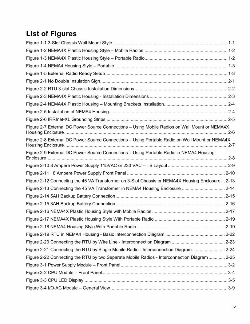
List of Figures Figure 1-1 3-Slot Chassis Wall Mount Style .......................................................................................... 1-1 Figure 1-2 NEMA4X Plastic Housing Style – Mobile Radios ................................................................. 1-2 Figure 1-3 NEMA4X Plastic Housing Style – Portable Radio................................................................. 1-2 Figure 1-4 NEMA4 Housing Style – Portable ........................................................................................ 1-3 Figure 1-5 External Radio Ready Setup................................................................................................ 1-3 Figure 2-1 No Double Insulation Sign.................................................................................................... 2-1 Figure 2-2 RTU 3-slot Chassis Installation Dimensions......................................................................... 2-2 Figure 2-3 NEMA4X Plastic Housing - Installation Dimensions ............................................................. 2-3 Figure 2-4 NEMA4X Plastic Housing – Mounting Brackets Installation.................................................. 2-4 Figure 2-5 Installation of NEMA4 Housing............................................................................................. 2-4 Figure 2-6 IRRInet-XL Grounding Strips ............................................................................................... 2-5 Figure 2-7 External DC Power Source Connections – Using Mobile Radios on Wall Mount or NEMA4X Housing Enclosure................................................................................................................................ 2-6 Figure 2-8 External DC Power Source Connections – Using Portable Radio on Wall Mount or NEMA4X Housing Enclosure................................................................................................................................ 2-7 Figure 2-9 External DC Power Source Connections – Using Portable Radio in NEMA4 Housing Enclosure.............................................................................................................................................. 2-8 Figure 2-10 8 Ampere Power Supply 115VAC or 230 VAC – TB Layout ............................................... 2-9 Figure 2-11 8 Ampere Power Supply Front Panel ............................................................................. 2-10 Figure 2-12 Connecting the 45 VA Transformer on 3-Slot Chassis or NEMA4X Housing Enclosure ... 2-13 Figure 2-13 Connecting the 45 VA Transformer in NEMA4 Housing Enclosure .................................. 2-14 Figure 2-14 5AH Backup Battery Connection...................................................................................... 2-15 Figure 2-15 3AH Backup Battery Connection...................................................................................... 2-16 Figure 2-16 NEMA4X Plastic Housing Style with Mobile Radios ......................................................... 2-17 Figure 2-17 NEMA4X Plastic Housing Style With Portable Radio ....................................................... 2-19 Figure 2-18 NEMA4 Housing Style With Portable Radio ..................................................................... 2-19 Figure 2-19 RTU in NEMA4 Housing - Basic Interconnection Diagram ............................................... 2-22 Figure 2-20 Connecting the RTU by Wire Line - Interconnection Diagram .......................................... 2-23 Figure 2-21 Connecting the RTU by Single Mobile Radio - Interconnection Diagram.......................... 2-24 Figure 2-22 Connecting the RTU by two Separate Mobile Radios - Interconnection Diagram ............. 2-25 Figure 3-1 Power Supply Module – Front Panel.................................................................................... 3-2 Figure 3-2 CPU Module – Front Panel .................................................................................................. 3-4 Figure 3-3 CPU LED Display................................................................................................................. 3-5 Figure 3-4 I/O-AC Module – General View............................................................................................ 3-9
v
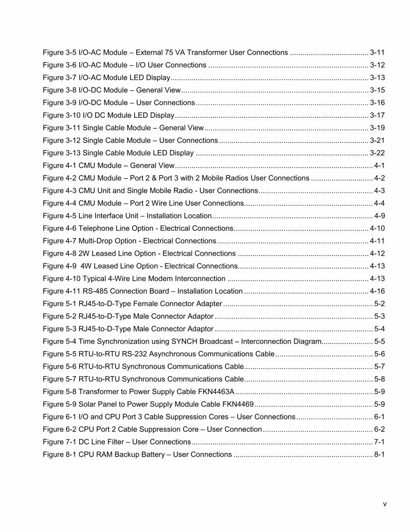
Figure 3-5 I/O-AC Module – External 75 VA Transformer User Connections ...................................... 3-11 Figure 3-6 I/O-AC Module – I/O User Connections ............................................................................. 3-12 Figure 3-7 I/O-AC Module LED Display............................................................................................... 3-13 Figure 3-8 I/O-DC Module – General View.......................................................................................... 3-15 Figure 3-9 I/O-DC Module – User Connections................................................................................... 3-16 Figure 3-10 I/O DC Module LED Display............................................................................................. 3-17 Figure 3-11 Single Cable Module – General View............................................................................... 3-19 Figure 3-12 Single Cable Module – User Connections........................................................................ 3-21 Figure 3-13 Single Cable Module LED Display ................................................................................... 3-22 Figure 4-1 CMU Module – General View............................................................................................... 4-1 Figure 4-2 CMU Module – Port 2 & Port 3 with 2 Mobile Radios User Connections .............................. 4-2 Figure 4-3 CMU Unit and Single Mobile Radio - User Connections....................................................... 4-3 Figure 4-4 CMU Module – Port 2 Wire Line User Connections.............................................................. 4-4 Figure 4-5 Line Interface Unit – Installation Location............................................................................. 4-9 Figure 4-6 Telephone Line Option - Electrical Connections................................................................. 4-10 Figure 4-7 Multi-Drop Option - Electrical Connections......................................................................... 4-11 Figure 4-8 2W Leased Line Option - Electrical Connections ............................................................... 4-12 Figure 4-9 4W Leased Line Option - Electrical Connections............................................................... 4-13 Figure 4-10 Typical 4-Wire Line Modem Interconnection .................................................................... 4-13 Figure 4-11 RS-485 Connection Board – Installation Location ............................................................ 4-16 Figure 5-1 RJ45-to-D-Type Female Connector Adapter ........................................................................ 5-2 Figure 5-2 RJ45-to-D-Type Male Connector Adaptor ............................................................................ 5-3 Figure 5-3 RJ45-to-D-Type Male Connector Adaptor ............................................................................ 5-4 Figure 5-4 Time Synchronization using SYNCH Broadcast – Interconnection Diagram......................... 5-5 Figure 5-5 RTU-to-RTU RS-232 Asynchronous Communications Cable............................................... 5-6 Figure 5-6 RTU-to-RTU Synchronous Communications Cable.............................................................. 5-7 Figure 5-7 RTU-to-RTU Synchronous Communications Cable.............................................................. 5-8 Figure 5-8 Transformer to Power Supply Cable FKN4463A .................................................................. 5-9 Figure 5-9 Solar Panel to Power Supply Module Cable FKN4469......................................................... 5-9 Figure 6-1 I/O and CPU Port 3 Cable Suppression Cores – User Connections..................................... 6-1 Figure 6-2 CPU Port 2 Cable Suppression Core – User Connection..................................................... 6-2 Figure 7-1 DC Line Filter – User Connections....................................................................................... 7-1 Figure 8-1 CPU RAM Backup Battery – User Connections ................................................................... 8-1
vi
List of Tables Table 1-1 RTU Models.....................................................................................................................1-4 Table 1-2 I/O & Communication Modules.........................................................................................1-5 Table 1-3 Power Supplies and Backup Battery Options ...................................................................1-6 Table 2-1 8 Ampere Power Supply – Front Panel Controls, Indicators, and Connectors ................ 2-10 Table 2-2 8 Ampere Power Supply Field Replaceable Parts .......................................................... 2-11 Table 2-3 45 VA Transformer Field Replaceable Parts .................................................................. 2-14 Table 2-4 5AH Backup Battery Field Replaceable Parts ................................................................ 2-15 Table 2-5 3AH Backup Battery Field Replaceable Parts ................................................................ 2-16 Table 2-6 Mobile Radio Field Replaceable Parts ........................................................................... 2-18 Table 2-7 Portable Radio Field Replaceable Parts......................................................................... 2-21 Table 2-8 IRRInet-XL Field Replaceable Parts............................................................................... 2-29 Table 3-1 Power Supply Module Field Replaceable Parts................................................................3-3 Table 3-2 CPU Matrix Display - LED Status Indications ...................................................................3-6 Table 3-3 CPU Module Field Replaceable Parts ..............................................................................3-8 Table 3-4 I/O-AC Module Indication Display .................................................................................. 3-13 Table 3-5 I/O-AC Module Field Replaceable Parts......................................................................... 3-14 Table 3-6 I/O-DC Module Diagnostic Led Display .......................................................................... 3-17 Table 3-7 I/O-DC Module Field Replaceable Parts ........................................................................ 3-18 Table 3-8 Single Cable Module - Diagnostic Led Display............................................................... 3-22 Table 3-9 Single Cable Module Field Replaceable Parts ............................................................... 3-24 Table 4-1 CMU and P3 Jumper Site Configuration settings per Radio and / or Wire Line: ...............4-5 Table 4-2 CMU Diagnostic Led Display ...........................................................................................4-7 Table 4-3 CMU Unit Field Replaceable Parts...................................................................................4-7 Table 4-4 Line Interface Unit - Connection Types ............................................................................4-8 Table 4-5 Line Interface Unit Field Replaceable Parts ................................................................... 4-15 Table 5-1 RTU to Modem Asynchronous Connection ......................................................................5-3 Table 5-2 RTU-to-Modem Synchronous Connection (DTE-to-DCE).................................................5-4 Table 6-1 Cable Suppression Cores Field Replaceable Parts..........................................................6-2 Table 7-1 DC Line Filter Field Replaceable Parts ............................................................................7-2
vii
Safety and General Information IMPORTANT INFORMATION ON SAFE AND EFFICIENT OPERATION. READ THIS INFORMATION BEFORE USING YOUR IRRInet-XL Terminal. Avoid risk of fire by only using fuses of the specified type and rating. For fuse replacement refer to qualified persons. Avoid electric shock from this equipment by supplying power from a properly grounded outlet. Prevent electric shock by always disconnecting the power line before servicing the equipment. This equipment does not have any user-serviceable parts. Do not remove panels or attempt to service this equipment unless you are instructed to do so.
Electromagnetic Interference / Compatibility The installer must make sure that the radio connected to the system has all required approvals. The installation must meet the requirements of the standard. This equipment was tested with cables 3 meters in length for indoor installation. If longer cables and/or cabinets for outdoor installation are used, the installer is responsible for making sure that the installation complies with the requirements of the standard. The product is a radio accessory. Medical Devices Pacemakers The Health Industry Manufacturers Association recommends that a minimum separation of 15 centimetres be maintained between a terminal and a pacemaker. These recommendations are consistent with the independent research by, and recommendations of, Wireless Technology Research. Persons with pacemakers should: ALWAYS keep the terminal more than 15 centimetres from their pacemaker when the IRRInet-XL is turned ON. Hearing Aids Some terminals may interfere with some hearing aids. In the event of such interference you may want to consult your hearing aid manufacturer to discuss alternatives. Other Medical Devices If you use any other personal medical device, consult the manufacturer of your device to determine if it is adequately shielded from RF energy. Your physician may be able to assist you in obtaining this information.
Antennas Do not use any terminal that has a damaged antenna. If a damaged antenna comes into contact with your skin, a minor burn can result. The antenna installation must comply with the following requirements in order to assure optimal performance and make sure human exposure to radio frequency electromagnetic energy is within the guidelines set forth in the above standards: The antenna must be mounted outside the building Mount the antenna on a tower if at all possible If the antenna is to be mounted on a building then it must be mounted on the roof. As with all fixed site antenna installations, it is the responsibility of the licensee to manage the site in accordance with applicable regulatory requirements and may require additional compliance actions such as site survey measurements, signage, and site access restrictions in order to insure that exposure limits are not exceeded.
Batteries All batteries can cause property damage and/or bodily injury such as burns if a conductive material such as jewellery, keys, or beaded chains touch exposed terminals. The conductive material may complete an electrical circuit (short circuit) and become quite hot. Exercise care in handling any charged battery, particularly when placing it inside a pocket, purse, or other container with metal objects. Battery Disposal For environmental protection used batteries should be disposed of properly for recycling. Never dispose of a battery on a fire as it may explode.
COPYRIGHT Copyright © 1999- 2001 Motorola Inc. All rights reserved. No part of this manual may be reproduced, transmitted, stored in a retrieval system, or translated into any language or computer language, in any form or by any means, without the prior written permission of Motorola Inc.
TRADEMARKS: Motorola and a are trademarks of Motorola Inc.
viii
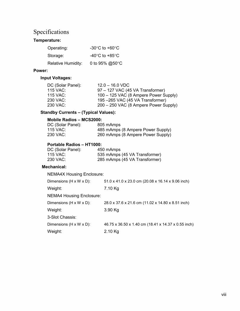
Specifications Temperature:
Operating: -30°C to +60°C
Storage: -40°C to +85°C
Relative Humidity: 0 to 95% @50°C Power:
Input Voltages: DC (Solar Panel): 12.0 – 16.0 VDC 115 VAC: 97 – 127 VAC (45 VA Transformer) 115 VAC: 100 – 125 VAC (8 Ampere Power Supply) 230 VAC: 195 –265 VAC (45 VA Transformer) 230 VAC: 200 – 250 VAC (8 Ampere Power Supply)
Standby Currents – (Typical Values): Mobile Radios – MCS2000: DC (Solar Panel): 805 mAmps 115 VAC: 485 mAmps (8 Ampere Power Supply) 230 VAC: 260 mAmps (8 Ampere Power Supply) Portable Radios – HT1000: DC (Solar Panel): 450 mAmps 115 VAC: 535 mAmps (45 VA Transformer) 230 VAC: 285 mAmps (45 VA Transformer)
Mechanical: NEMA4X Housing Enclosure: Dimensions (H x W x D): 51.0 x 41.0 x 23.0 cm (20.08 x 16.14 x 9.06 inch)
Weight: 7.10 Kg NEMA4 Housing Enclosure: Dimensions (H x W x D): 28.0 x 37.6 x 21.6 cm (11.02 x 14.80 x 8.51 inch)
Weight: 3.90 Kg 3-Slot Chassis: Dimensions (H x W x D): 46.75 x 36.50 x 1.40 cm (18.41 x 14.37 x 0.55 inch)
Weight: 2.10 Kg

ix
Scope of This Manual This manual provides installation and operation instructions for the IRRInet-XL RTU (Remote Terminal Unit). It also provides on-site replacement instructions for RTU elements that do not necessarily require shop level assistance. This manual also covers the enclosure assemblies, communication options, and various Input / Output (I/O) options.
1-1
CHAPTER 1 General Description
The IRRInet-XL is a field irrigation controller designed for many irrigation applications, such as: turf, landscaping, highway medians, and agricultural. The RTU can operate as a smart stand-alone controller, or as part of a larger distributed irrigation system that communicates by radio(s) or \ and wire line(s) connection(s). The IRRInet-XL is a modular unit made up of 3 I/O plug-in modules (installed in a 3-slot I/O card cage) CPU Module, Power Supply Module, radio(s) and AC Power Supply. Figure 1-1 shows a typical RTU setup.
The RTU can be powered by a battery or solar panel. This option is useful where AC power is not available. For DC power connections see “Electrical Connections for External DC Power Supply” in the Installation section.
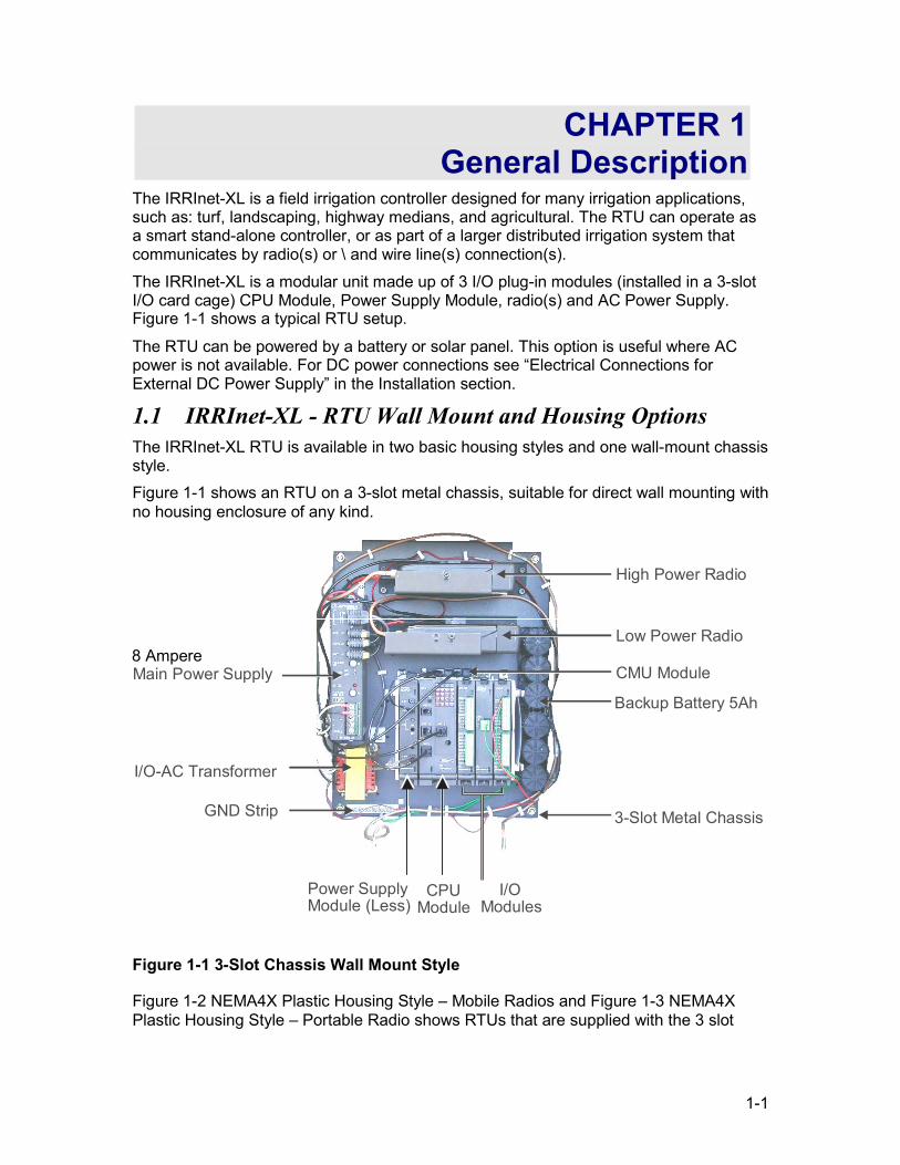
1.1 IRRInet-XL - RTU Wall Mount and Housing Options The IRRInet-XL RTU is available in two basic housing styles and one wall-mount chassis style. Figure 1-1 shows an RTU on a 3-slot metal chassis, suitable for direct wall mounting with no housing enclosure of any kind.
High Power Radio
Low Power Radio
CMU Module
Backup Battery 5Ah
3-Slot Metal Chassis
I/O Modules
CPUModule
Power SupplyModule (Less)
Main Power Supply
I/O-AC Transformer
GND Strip
Figure 1-1 3-Slot Chassis Wall Mount Style
Figure 1-2 NEMA4X Plastic Housing Style – Mobile Radios and Figure 1-3 NEMA4X Plastic Housing Style – Portable Radio shows RTUs that are supplied with the 3 slot
8 Ampere
1-2
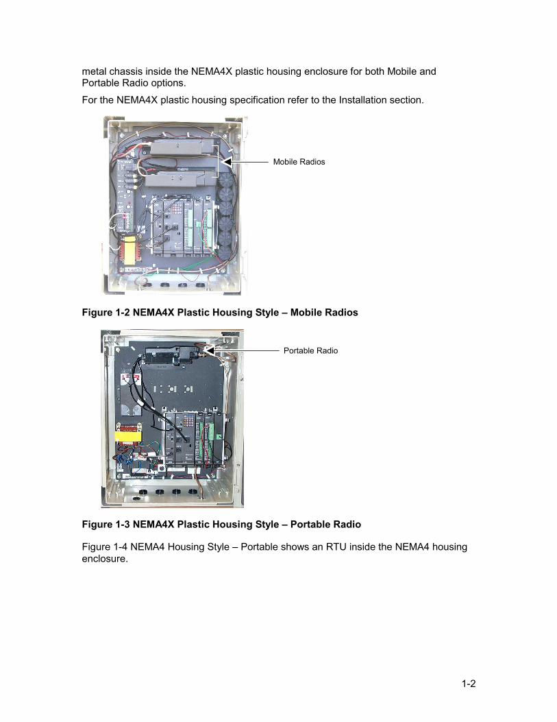
metal chassis inside the NEMA4X plastic housing enclosure for both Mobile and Portable Radio options. For the NEMA4X plastic housing specification refer to the Installation section.
Figure 1-2 NEMA4X Plastic Housing Style – Mobile Radios
Figure 1-3 NEMA4X Plastic Housing Style – Portable Radio
Figure 1-4 NEMA4 Housing Style – Portable shows an RTU inside the NEMA4 housing enclosure.
Portable Radio
Mobile Radios
1-3
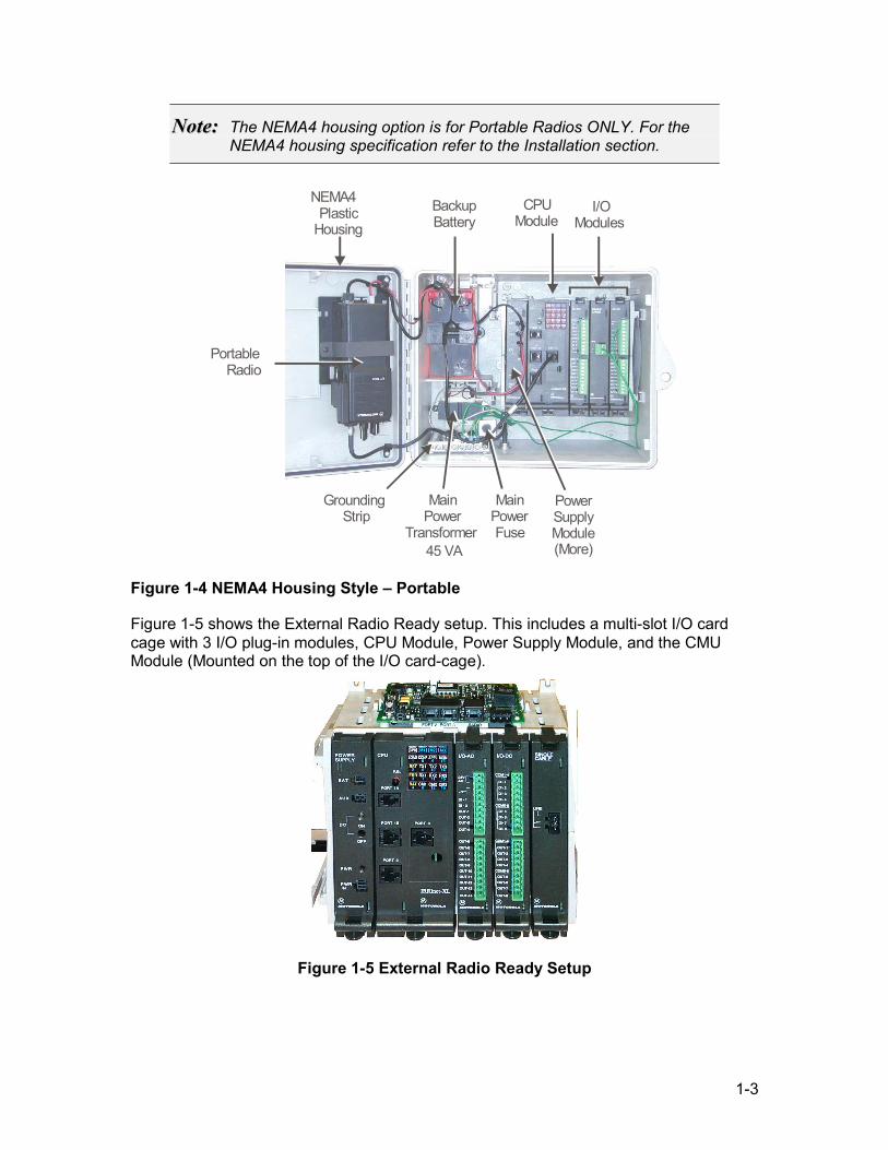
NNoottee:: The NEMA4 housing option is for Portable Radios ONLY. For the NEMA4 housing specification refer to the Installation section.
BackupBattery
Portable Radio
NEMA4 Plastic
HousingI/O
ModulesCPU
Module
GroundingStrip
PowerSupply Module (More)
Main Power
Transformer45 VA
MainPower Fuse
Figure 1-4 NEMA4 Housing Style – Portable
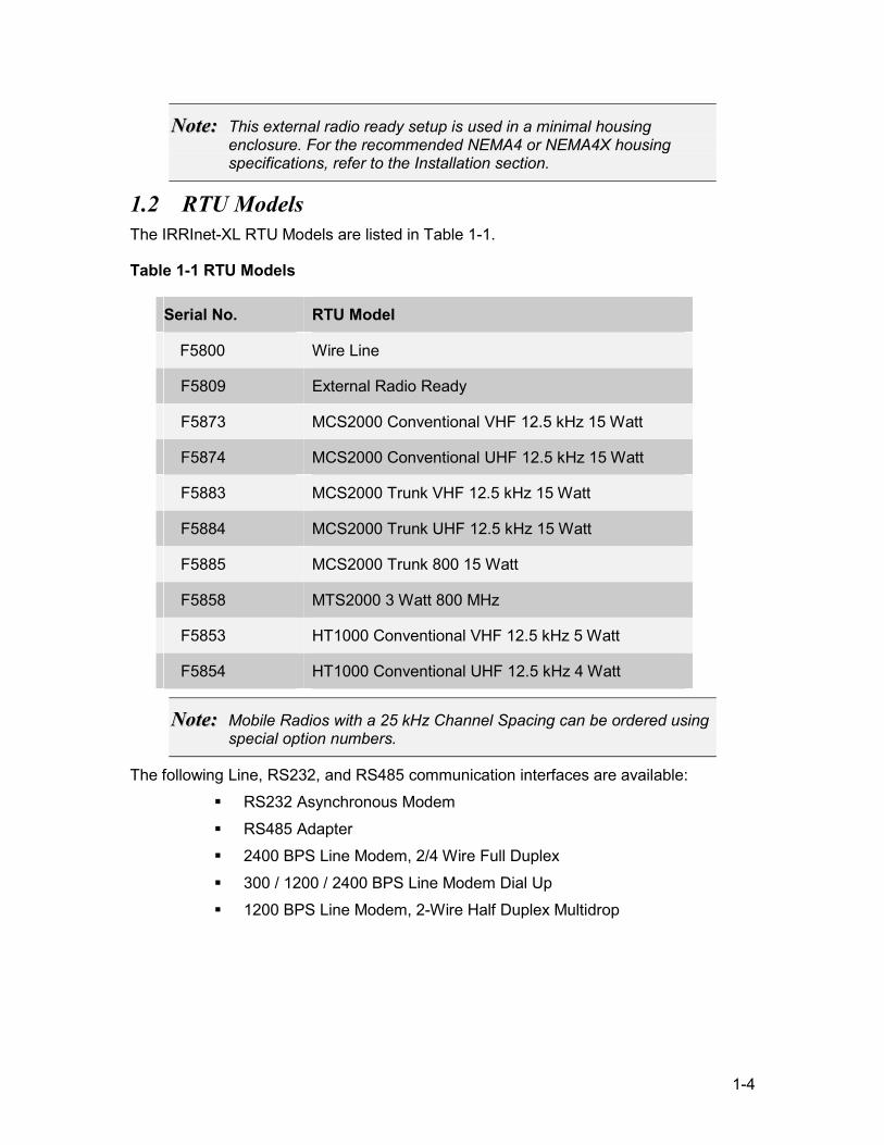
Figure 1-5 shows the External Radio Ready setup. This includes a multi-slot I/O card cage with 3 I/O plug-in modules, CPU Module, Power Supply Module, and the CMU Module (Mounted on the top of the I/O card-cage).
Figure 1-5 External Radio Ready Setup
1-4
NNoottee:: This external radio ready setup is used in a minimal housing enclosure. For the recommended NEMA4 or NEMA4X housing specifications, refer to the Installation section.
1.2 RTU Models The IRRInet-XL RTU Models are listed in Table 1-1.
Table 1-1 RTU Models
Serial No. RTU Model
F5800 Wire Line
F5809 External Radio Ready
F5873 MCS2000 Conventional VHF 12.5 kHz 15 Watt
F5874 MCS2000 Conventional UHF 12.5 kHz 15 Watt
F5883 MCS2000 Trunk VHF 12.5 kHz 15 Watt
F5884 MCS2000 Trunk UHF 12.5 kHz 15 Watt
F5885 MCS2000 Trunk 800 15 Watt
F5858 MTS2000 3 Watt 800 MHz
F5853 HT1000 Conventional VHF 12.5 kHz 5 Watt
F5854 HT1000 Conventional UHF 12.5 kHz 4 Watt
NNoottee:: Mobile Radios with a 25 kHz Channel Spacing can be ordered using special option numbers.
The following Line, RS232, and RS485 communication interfaces are available: RS232 Asynchronous Modem RS485 Adapter 2400 BPS Line Modem, 2/4 Wire Full Duplex 300 / 1200 / 2400 BPS Line Modem Dial Up 1200 BPS Line Modem, 2-Wire Half Duplex Multidrop
1-5
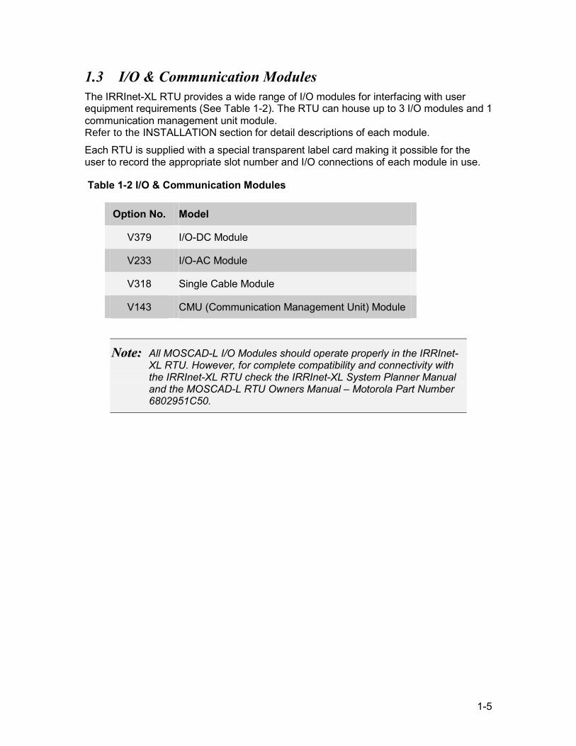
1.3 I/O & Communication Modules The IRRInet-XL RTU provides a wide range of I/O modules for interfacing with user equipment requirements (See Table 1-2). The RTU can house up to 3 I/O modules and 1 communication management unit module. Refer to the INSTALLATION section for detail descriptions of each module. Each RTU is supplied with a special transparent label card making it possible for the user to record the appropriate slot number and I/O connections of each module in use.
Table 1-2 I/O & Communication Modules
Option No. Model
V379 I/O-DC Module
V233 I/O-AC Module
V318 Single Cable Module
V143 CMU (Communication Management Unit) Module
NNoottee:: All MOSCAD-L I/O Modules should operate properly in the IRRInet-XL RTU. However, for complete compatibility and connectivity with the IRRInet-XL RTU check the IRRInet-XL System Planner Manual and the MOSCAD-L RTU Owners Manual – Motorola Part Number 6802951C50.
1-6
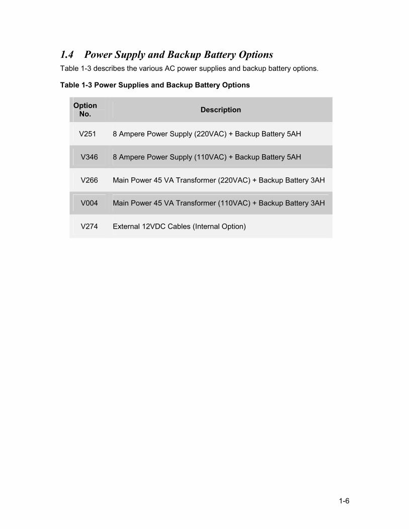
1.4 Power Supply and Backup Battery Options Table 1-3 describes the various AC power supplies and backup battery options.
Table 1-3 Power Supplies and Backup Battery Options
Option No. Description
V251 8 Ampere Power Supply (220VAC) + Backup Battery 5AH
V346 8 Ampere Power Supply (110VAC) + Backup Battery 5AH
V266 Main Power 45 VA Transformer (220VAC) + Backup Battery 3AH
V004 Main Power 45 VA Transformer (110VAC) + Backup Battery 3AH
V274 External 12VDC Cables (Internal Option)
2-1
CHAPTER 2 INSTALLATION
This chapter provides mounting, assembly, disassembly, and connection instructions for all models of the IRRInet-XL. This chapter also provides part numbers of field replaceable components. This chapter covers the following installation procedures:
1. Wall Mounting with and without a Housing enclosure 2. Module Preparation and Installation 3. Electrical Connections
2.1 Before Mounting the RTU Only qualified and authorized technicians should install the IRRInet-XL RTU. If
the installation involves high-voltage connections technicians must be specifically qualified to handle such high voltages.
When the IRRInet-XL is operated from a DC power source and has mobile radio(s), use a 10 Amp disconnect device (circuit breaker) in series to the DC power cable according to the local electrical standards and requirements.
When the IRRInet-XL is operated from a DC power source and has a portable radio, a use 5 Amp disconnect device (circuit breaker) in series to the AC power cable according to the local electrical standards and requirements.
When the IRRInet-XL is operated from an AC power source by 8 Ampere power supply; use 10 Amp disconnect device (circuit breaker) in series to the AC power cable according to the local electrical standards and requirements.
When the IRRInet-XL is operated from an AC power source by 45 VA Main Power Transformer; use 6 Amp disconnect device (circuit breaker) in series to the DC power cable, according to the local electrical standards and requirements.
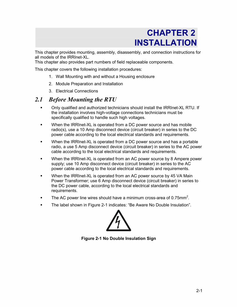
The AC power line wires should have a minimum cross-area of 0.75mm2. The label shown in Figure 2-1 indicates: “Be Aware No Double Insulation”.
Figure 2-1 No Double Insulation Sign
2-2
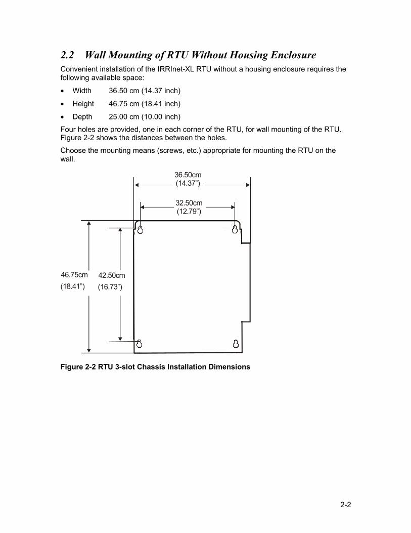
2.2 Wall Mounting of RTU Without Housing Enclosure Convenient installation of the IRRInet-XL RTU without a housing enclosure requires the following available space:
• Width 36.50 cm (14.37 inch)
• Height 46.75 cm (18.41 inch)
• Depth 25.00 cm (10.00 inch) Four holes are provided, one in each corner of the RTU, for wall mounting of the RTU. Figure 2-2 shows the distances between the holes.
Choose the mounting means (screws, etc.) appropriate for mounting the RTU on the wall.
32.50cm (12.79”)
36.50cm (14.37”)
(18.41”) 46.75cm
(16.73”) 42.50cm
Figure 2-2 RTU 3-slot Chassis Installation Dimensions
2-3
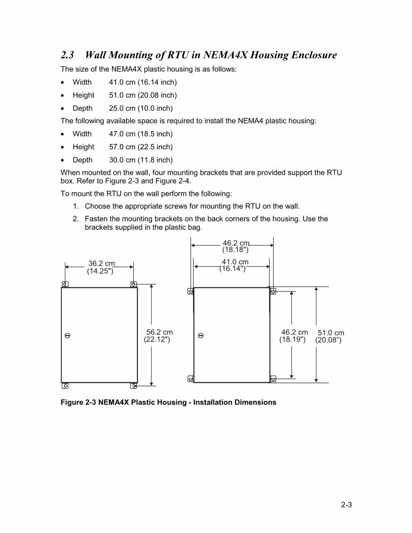
2.3 Wall Mounting of RTU in NEMA4X Housing Enclosure The size of the NEMA4X plastic housing is as follows:
• Width 41.0 cm (16.14 inch)
• Height 51.0 cm (20.08 inch)
• Depth 25.0 cm (10.0 inch) The following available space is required to install the NEMA4 plastic housing:
• Width 47.0 cm (18.5 inch)
• Height 57.0 cm (22.5 inch)
• Depth 30.0 cm (11.8 inch) When mounted on the wall, four mounting brackets that are provided support the RTU box. Refer to Figure 2-3 and Figure 2-4.
To mount the RTU on the wall perform the following: 1. Choose the appropriate screws for mounting the RTU on the wall. 2. Fasten the mounting brackets on the back corners of the housing. Use the
brackets supplied in the plastic bag.
36.2 cm (14.25")
56.2 cm (22.12")
46.2 cm (18.19")
46.2 cm (18.18")
51.0 cm(20.08”)
41.0 cm(16.14")
Figure 2-3 NEMA4X Plastic Housing - Installation Dimensions
2-4
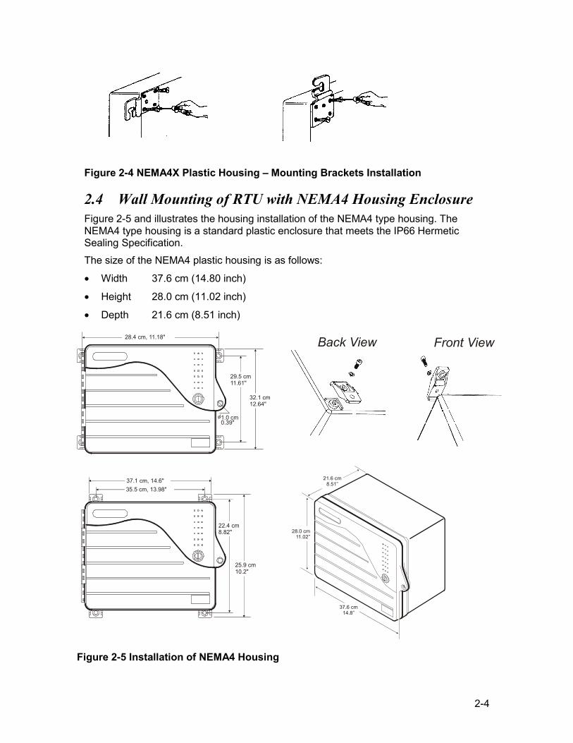
Figure 2-4 NEMA4X Plastic Housing – Mounting Brackets Installation
2.4 Wall Mounting of RTU with NEMA4 Housing Enclosure Figure 2-5 and illustrates the housing installation of the NEMA4 type housing. The NEMA4 type housing is a standard plastic enclosure that meets the IP66 Hermetic Sealing Specification. The size of the NEMA4 plastic housing is as follows:
• Width 37.6 cm (14.80 inch)
• Height 28.0 cm (11.02 inch)
• Depth 21.6 cm (8.51 inch)
28.4 cm, 11.18"
29.5 cm11.61"
32.1 cm12.64"
37.1 cm, 14.6"35.5 cm, 13.98"
22.4 cm8.82"
25.9 cm10.2"
1.0 cm0.39"
Back View Front View
21.6 cm8.51”
28.0 cm11.02”
37.6 cm14.8”
Figure 2-5 Installation of NEMA4 Housing
2-5
2.5 Electrical Connections
NNoottee:: - To comply with CE and FCC Standards, Cable Suppression Cores (Ferrites) must be installed on all I/O and communication cables connected to Port 2 and Port 3 of the CPU. Refer to CHAPTER 6 for assembly instructions. - To comply with CE standards a DC line filter should be used when the IRRInet-XL with a portable radio and a power supply (Less) module (FPN5957) is powered from a DC power source (such as solar panel). This DC Line Filter is supplied with the option number V274. Refer to CHAPTER 7 for assembly instructions.
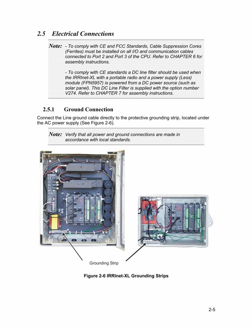
2.5.1 Ground Connection Connect the Line ground cable directly to the protective grounding strip, located under the AC power supply (See Figure 2-6).
NNoottee:: Verify that all power and ground connections are made in accordance with local standards.
Grounding Strip
Figure 2-6 IRRInet-XL Grounding Strips
2-6
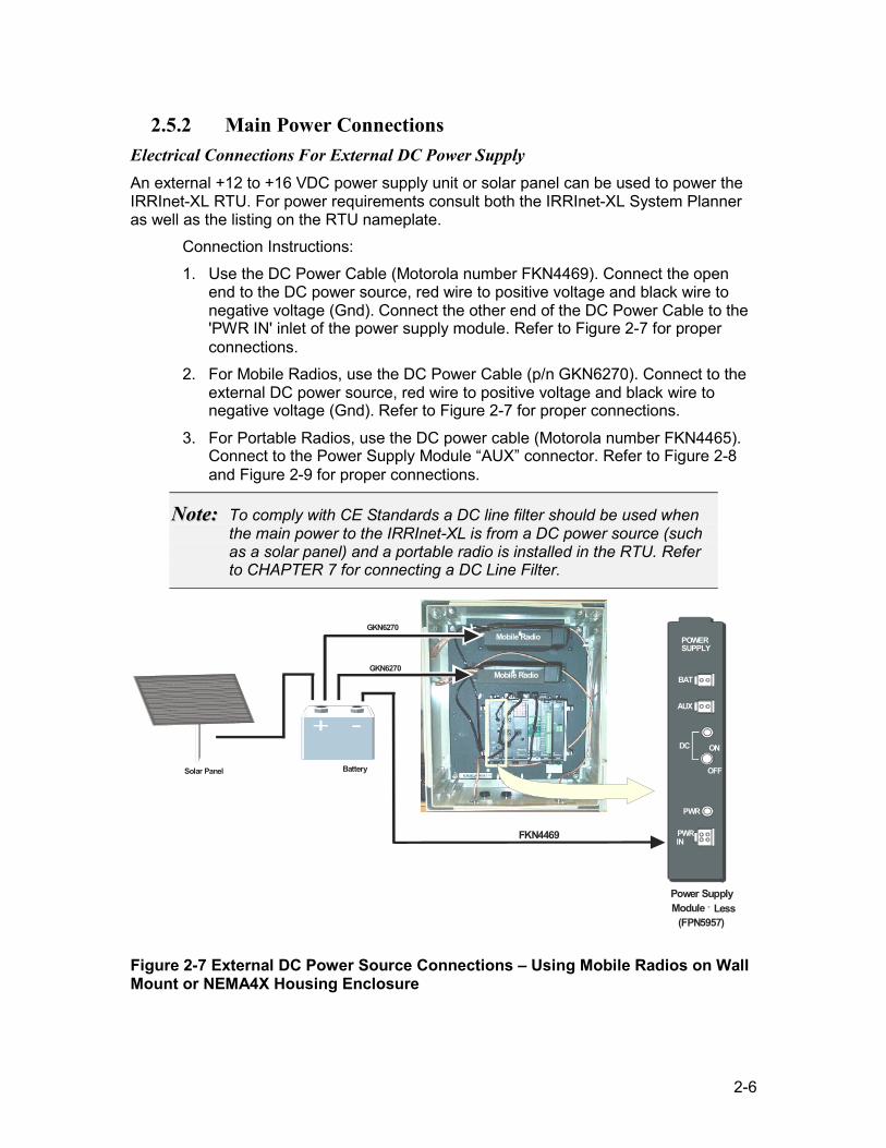
2.5.2 Main Power Connections Electrical Connections For External DC Power Supply An external +12 to +16 VDC power supply unit or solar panel can be used to power the IRRInet-XL RTU. For power requirements consult both the IRRInet-XL System Planner as well as the listing on the RTU nameplate.
Connection Instructions: 1. Use the DC Power Cable (Motorola number FKN4469). Connect the open
end to the DC power source, red wire to positive voltage and black wire to negative voltage (Gnd). Connect the other end of the DC Power Cable to the 'PWR IN' inlet of the power supply module. Refer to Figure 2-7 for proper connections.
2. For Mobile Radios, use the DC Power Cable (p/n GKN6270). Connect to the external DC power source, red wire to positive voltage and black wire to negative voltage (Gnd). Refer to Figure 2-7 for proper connections.
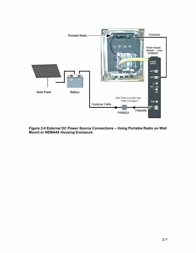
3. For Portable Radios, use the DC power cable (Motorola number FKN4465). Connect to the Power Supply Module “AUX” connector. Refer to Figure 2-8 and Figure 2-9 for proper connections.
NNoottee:: To comply with CE Standards a DC line filter should be used when the main power to the IRRInet-XL is from a DC power source (such as a solar panel) and a portable radio is installed in the RTU. Refer to CHAPTER 7 for connecting a DC Line Filter.
POWER SUPPLY
BAT
AUX
DC ON
OFF
PWR
PWR IN
FKN4469
Power Supply Module - Less
(FPN5957)
Solar Panel Battery
GKN6270
GKN6270
Mobile Radio
Mobile Radio
Figure 2-7 External DC Power Source Connections – Using Mobile Radios on Wall Mount or NEMA4X Housing Enclosure
2-7
POWER SUPPLY BAT
AUX DC ON
OFF
PWR PWR IN Customer Cable
FKN4465
Power Supply Module - Less
(FPN5957)
Solar Panel Battery
Portable Radio
Note: Place Line filter here. Refer to Chapter 7
FKN8024 FKN4469
Figure 2-8 External DC Power Source Connections – Using Portable Radio on Wall Mount or NEMA4X Housing Enclosure
2-8
POWER SUPPLY
BAT
AUX
DC ON
OFF
PWR
PWR IN
FKN4465
Power Supply Module - Less
(FPN5957) Portable
Radio
Note: Place Line filter here. Solar Panel Battery
Customer Cable Refer to Chapter 7
FKN8024FKN4469
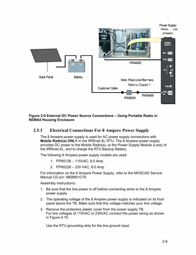
Figure 2-9 External DC Power Source Connections – Using Portable Radio in NEMA4 Housing Enclosure
2.5.3 Electrical Connections For 8 Ampere Power Supply The 8 Ampere power supply is used for AC power supply connections with Mobile Radio(s) ONLY in the IRRInet-XL RTU. The 8 Ampere power supply provides DC power to the Mobile Radio(s), to the Power Supply Module (Less) of the IRRInet-XL, and to charge the RTU Backup Battery. The following 8 Ampere power supply models are used:
1. FPN5128 – 115VAC, 8.0 Amp 2. FPN5228 – 230 VAC, 8.0 Amp
For information on the 8 Ampere Power Supply, refer to the MOSCAD Service Manual CD p/n: 9808901C76. Assembly Instructions: 1. Be sure that the line power is off before connecting wires to the 8 Ampere
power supply. 2. The operating voltage of the 8 Ampere power supply is indicated on its front
panel above the TB. Make sure that this voltage matches your line voltage. 3. Remove the protective plastic cover from the power supply TB.
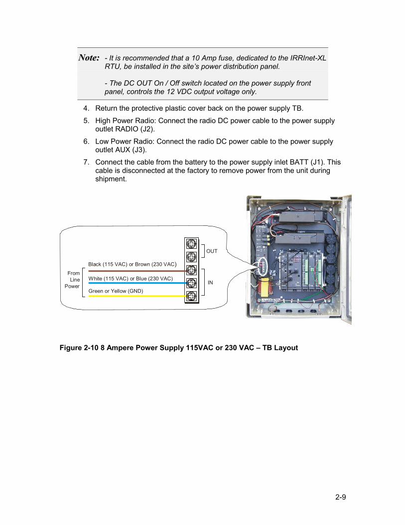
For line voltages of 115VAC or 230VAC connect the power wiring as shown in Figure 2-10. Use the RTU grounding strip for the line ground input.
2-9
NNoottee:: - It is recommended that a 10 Amp fuse, dedicated to the IRRInet-XL RTU, be installed in the site’s power distribution panel. - The DC OUT On / Off switch located on the power supply front panel, controls the 12 VDC output voltage only.
4. Return the protective plastic cover back on the power supply TB. 5. High Power Radio: Connect the radio DC power cable to the power supply
outlet RADIO (J2). 6. Low Power Radio: Connect the radio DC power cable to the power supply
outlet AUX (J3). 7. Connect the cable from the battery to the power supply inlet BATT (J1). This
cable is disconnected at the factory to remove power from the unit during shipment.
OUT
IN
Black (115 VAC) or Brown (230 VAC)
White (115 VAC) or Blue (230 VAC)
Green or Yellow (GND)
From Line
Power
Figure 2-10 8 Ampere Power Supply 115VAC or 230 VAC – TB Layout
2-10
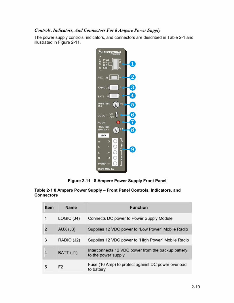
Controls, Indicators, And Connectors For 8 Ampere Power Supply The power supply controls, indicators, and connectors are described in Table 2-1 and illustrated in Figure 2-11.
N
L
L
N
P GND
230 V 50Hz 1A
230V
FUSE (SB)250V 3A T
FUSE (SB)10A
AC ON
OFFON
DC OUT
J1BATT
RADIO
AUX J3
LOGIC
+
+
+
F2
+G
G
FPN5225A
P OXP FD DL B
J2
230V
F1
Figure 2-11 8 Ampere Power Supply Front Panel
Table 2-1 8 Ampere Power Supply – Front Panel Controls, Indicators, and Connectors
Item Name Function
1 LOGIC (J4) Connects DC power to Power Supply Module
2 AUX (J3) Supplies 12 VDC power to “Low Power” Mobile Radio
3 RADIO (J2) Supplies 12 VDC power to “High Power” Mobile Radio
4 BATT (J1) Interconnects 12 VDC power from the backup battery to the power supply
5 F2 Fuse (10 Amp) to protect against DC power overload to battery
2-11
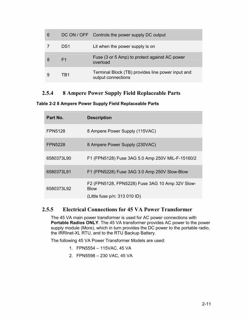
6 DC ON / OFF Controls the power supply DC output
7 DS1 Lit when the power supply is on
8 F1 Fuse (3 or 5 Amp) to protect against AC power overload
9 TB1 Terminal Block (TB) provides line power input and output connections
2.5.4 8 Ampere Power Supply Field Replaceable Parts
Table 2-2 8 Ampere Power Supply Field Replaceable Parts
Part No. Description
FPN5128 8 Ampere Power Supply (115VAC)
FPN5228 8 Ampere Power Supply (230VAC)
6580373L90 F1 (FPN5128) Fuse 3AG 5.0 Amp 250V MIL-F-15160/2
6580373L91 F1 (FPN5228) Fuse 3AG 3.0 Amp 250V Slow-Blow
6580373L92 F2 (FPN5128, FPN5228) Fuse 3AG 10 Amp 32V Slow-Blow (Little fuse p/n: 313 010 ID)
2.5.5 Electrical Connections for 45 VA Power Transformer The 45 VA main power transformer is used for AC power connections with Portable Radios ONLY. The 45 VA transformer provides AC power to the power supply module (More), which in turn provides the DC power to the portable radio, the IRRInet-XL RTU, and to the RTU Backup Battery. The following 45 VA Power Transformer Models are used:
1. FPN5554 – 115VAC, 45 VA 2. FPN5598 – 230 VAC, 45 VA
2-12
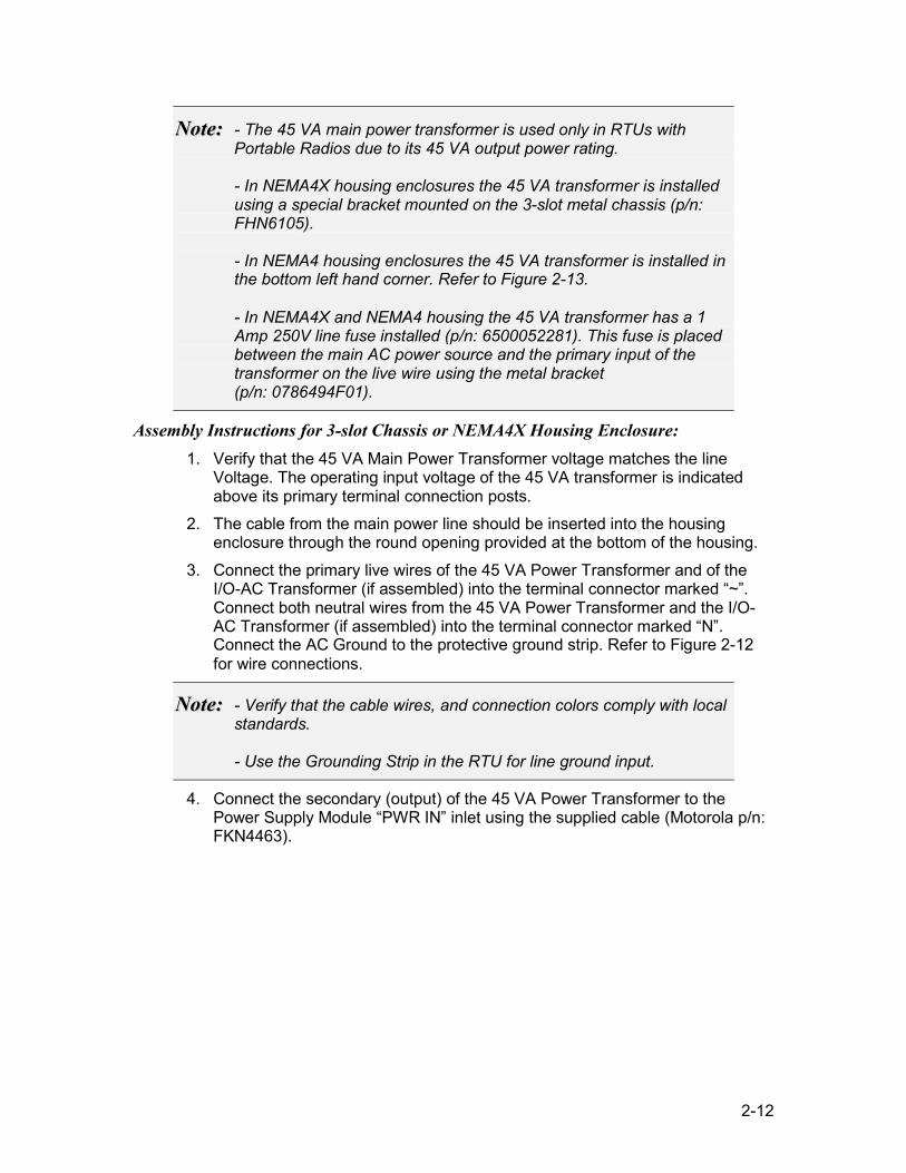
NNoottee:: - The 45 VA main power transformer is used only in RTUs with Portable Radios due to its 45 VA output power rating. - In NEMA4X housing enclosures the 45 VA transformer is installed using a special bracket mounted on the 3-slot metal chassis (p/n: FHN6105). - In NEMA4 housing enclosures the 45 VA transformer is installed in the bottom left hand corner. Refer to Figure 2-13. - In NEMA4X and NEMA4 housing the 45 VA transformer has a 1 Amp 250V line fuse installed (p/n: 6500052281). This fuse is placed between the main AC power source and the primary input of the transformer on the live wire using the metal bracket (p/n: 0786494F01).
Assembly Instructions for 3-slot Chassis or NEMA4X Housing Enclosure: 1. Verify that the 45 VA Main Power Transformer voltage matches the line
Voltage. The operating input voltage of the 45 VA transformer is indicated above its primary terminal connection posts.
2. The cable from the main power line should be inserted into the housing enclosure through the round opening provided at the bottom of the housing.
3. Connect the primary live wires of the 45 VA Power Transformer and of the I/O-AC Transformer (if assembled) into the terminal connector marked “~”. Connect both neutral wires from the 45 VA Power Transformer and the I/O-AC Transformer (if assembled) into the terminal connector marked “N”. Connect the AC Ground to the protective ground strip. Refer to Figure 2-12 for wire connections.
NNoottee:: - Verify that the cable wires, and connection colors comply with local standards. - Use the Grounding Strip in the RTU for line ground input.
4. Connect the secondary (output) of the 45 VA Power Transformer to the Power Supply Module “PWR IN” inlet using the supplied cable (Motorola p/n: FKN4463).
2-13
Black (115 VAC) or Brown (230 VAC)
White (115 VAC) or Blue (230 VAC)
Green or Yellow (GND)
From Line
Power
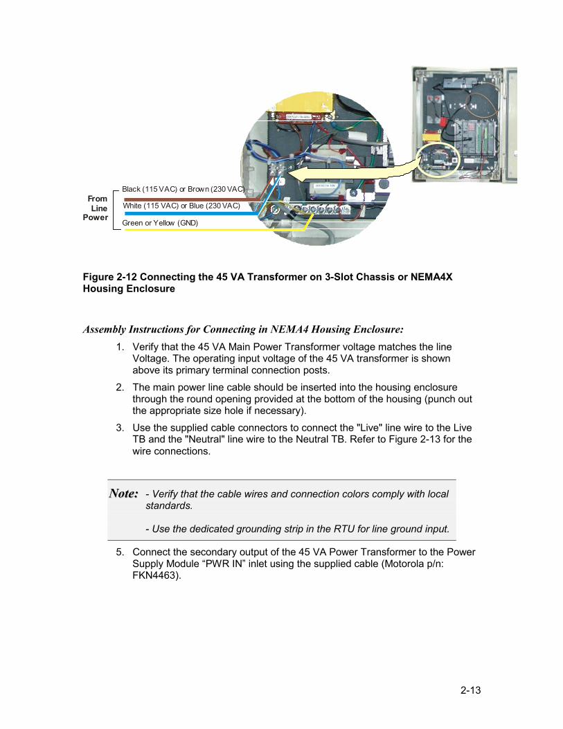
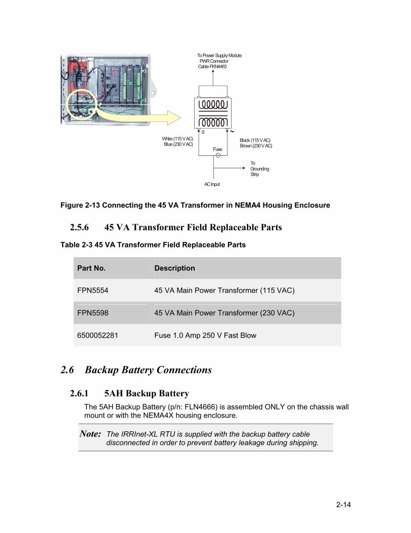
Figure 2-12 Connecting the 45 VA Transformer on 3-Slot Chassis or NEMA4X Housing Enclosure
Assembly Instructions for Connecting in NEMA4 Housing Enclosure: 1. Verify that the 45 VA Main Power Transformer voltage matches the line
Voltage. The operating input voltage of the 45 VA transformer is shown above its primary terminal connection posts.
2. The main power line cable should be inserted into the housing enclosure through the round opening provided at the bottom of the housing (punch out the appropriate size hole if necessary).
3. Use the supplied cable connectors to connect the "Live" line wire to the Live TB and the "Neutral" line wire to the Neutral TB. Refer to Figure 2-13 for the wire connections.
NNoottee:: - Verify that the cable wires and connection colors comply with local standards. - Use the dedicated grounding strip in the RTU for line ground input.
5. Connect the secondary output of the 45 VA Power Transformer to the Power Supply Module “PWR IN” inlet using the supplied cable (Motorola p/n: FKN4463).
2-14
AC Input
To Grounding Strip
Fuse
Black (115 V AC) Brown (230 V AC) White (115 V AC)
Blue (230 V AC)
To Power Supply ModulePWR Connector
Cable FKN4463
0
Figure 2-13 Connecting the 45 VA Transformer in NEMA4 Housing Enclosure
2.5.6 45 VA Transformer Field Replaceable Parts
Table 2-3 45 VA Transformer Field Replaceable Parts
Part No. Description
FPN5554 45 VA Main Power Transformer (115 VAC)
FPN5598 45 VA Main Power Transformer (230 VAC)
6500052281 Fuse 1.0 Amp 250 V Fast Blow
2.6 Backup Battery Connections
2.6.1 5AH Backup Battery The 5AH Backup Battery (p/n: FLN4666) is assembled ONLY on the chassis wall mount or with the NEMA4X housing enclosure.
NNoottee:: The IRRInet-XL RTU is supplied with the backup battery cable disconnected in order to prevent battery leakage during shipping.
2-15
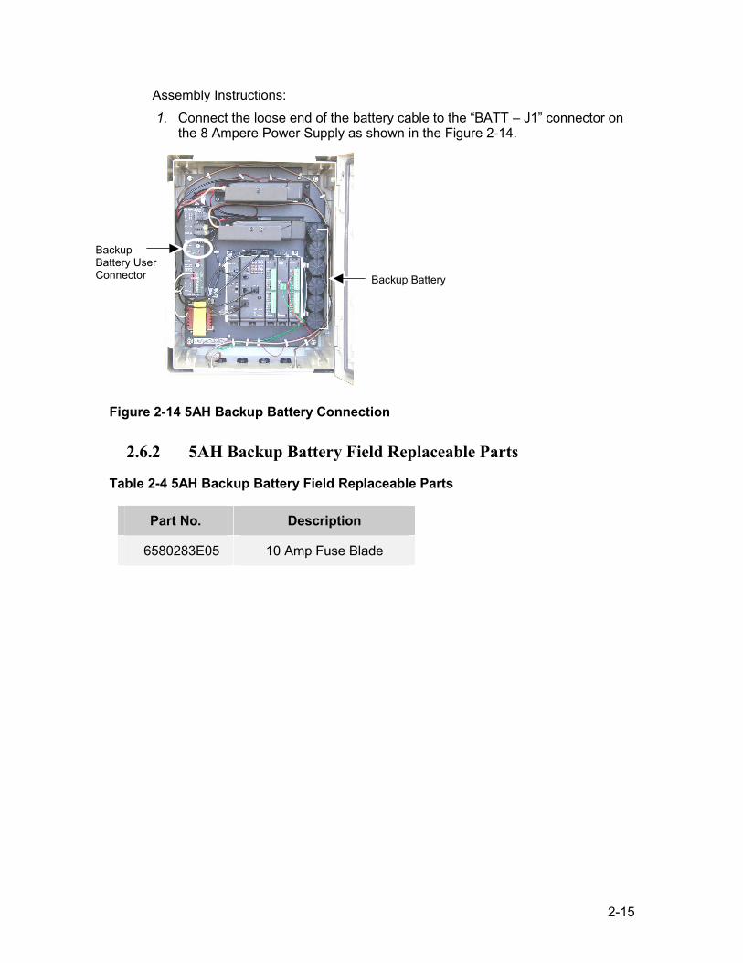
Assembly Instructions: 1. Connect the loose end of the battery cable to the “BATT – J1” connector on
the 8 Ampere Power Supply as shown in the Figure 2-14.
Figure 2-14 5AH Backup Battery Connection
2.6.2 5AH Backup Battery Field Replaceable Parts
Table 2-4 5AH Backup Battery Field Replaceable Parts
Part No. Description
6580283E05 10 Amp Fuse Blade
Backup Battery
Backup Battery User Connector
2-16
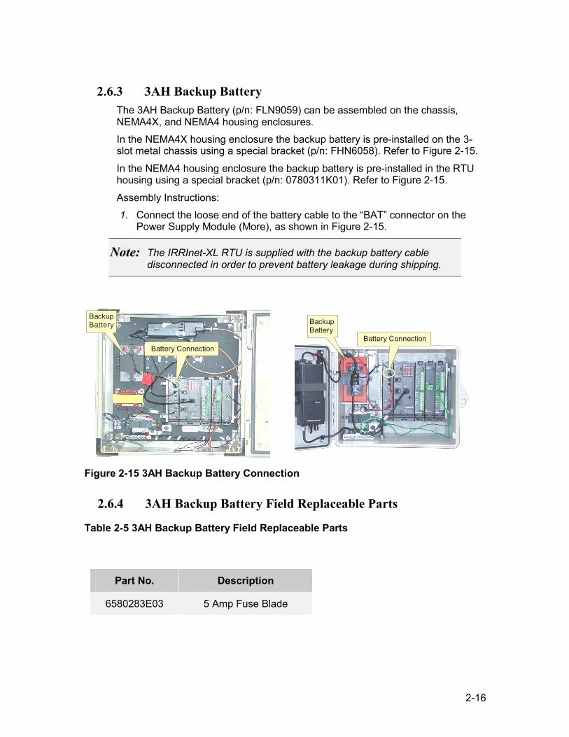
2.6.3 3AH Backup Battery The 3AH Backup Battery (p/n: FLN9059) can be assembled on the chassis, NEMA4X, and NEMA4 housing enclosures. In the NEMA4X housing enclosure the backup battery is pre-installed on the 3-slot metal chassis using a special bracket (p/n: FHN6058). Refer to Figure 2-15.
In the NEMA4 housing enclosure the backup battery is pre-installed in the RTU housing using a special bracket (p/n: 0780311K01). Refer to Figure 2-15.
Assembly Instructions: 1. Connect the loose end of the battery cable to the “BAT” connector on the
Power Supply Module (More), as shown in Figure 2-15.
NNoottee:: The IRRInet-XL RTU is supplied with the backup battery cable disconnected in order to prevent battery leakage during shipping.
Battery Connection Battery Connection
BackupBattery
BackupBattery
Figure 2-15 3AH Backup Battery Connection
2.6.4 3AH Backup Battery Field Replaceable Parts
Table 2-5 3AH Backup Battery Field Replaceable Parts
Part No. Description
6580283E03 5 Amp Fuse Blade
2-17
2.7 Radio Connections The IRRInet-XL RTU may contain either Mobile (High and/or Low Power) or Portable radios. The 3-slot chassis is compatible with both Mobile and Portable radios; refer to Figure 1-2 and Figure 1-3. The NEMA4 housing enclosure is compatible with only the Portable Radio. Refer to Figure 1-4.
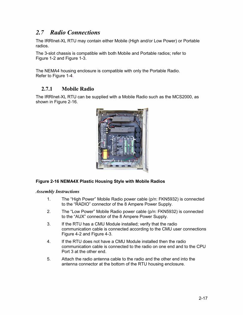
2.7.1 Mobile Radio The IRRInet-XL RTU can be supplied with a Mobile Radio such as the MCS2000, as shown in Figure 2-16.
Figure 2-16 NEMA4X Plastic Housing Style with Mobile Radios
Assembly Instructions 1. The “High Power” Mobile Radio power cable (p/n: FKN5932) is connected
to the “RADIO” connector of the 8 Ampere Power Supply. 2. The “Low Power” Mobile Radio power cable (p/n: FKN5932) is connected
to the “AUX” connector of the 8 Ampere Power Supply. 3. If the RTU has a CMU Module installed; verify that the radio
communication cable is connected according to the CMU user connections Figure 4-2 and Figure 4-3.
4. If the RTU does not have a CMU Module installed then the radio communication cable is connected to the radio on one end and to the CPU Port 3 at the other end.
5. Attach the radio antenna cable to the radio and the other end into the antenna connector at the bottom of the RTU housing enclosure.
2-18
NNoottee:: Setting the radio volume level is insignificant. However, set the volume knob to minimum to save battery power in case of power failure.
Operation Turn the radio ON-OFF/Volume knob to the ON position.
Removing The Mobile Radio To remove the radio from the RTU proceed as follows:
1. Turn off the DC power. 2. Disconnect the DC power and antenna cable from the radio. 3. Disconnect the communication cable. 4. Remove the screws securing the radio to its mounting bracket.
Installing The Mobile Radio To install the radio from the RTU proceed as follows:
1. Turn off the DC power. 2. Place the radio and secure the screw of the mounting bracket to the door. 3. Reconnect the communication cable. 4. Reconnect the DC power and antenna cables to the radio.
2.7.2 Mobile Radio Field Replaceable Parts
Table 2-6 Mobile Radio Field Replaceable Parts
Part No. Description
FRN5843 MCS2000 Adapter Connector
FKN5932 Mobile Radio Power Cable to 8 Ampere Power Supply
GKN6270 Mobile Radio Power Cable to Solar Panel
FKN5952 Mobile Radio Antenna Cable
FKN5953 Mobile Radio Communication Cable
2-19
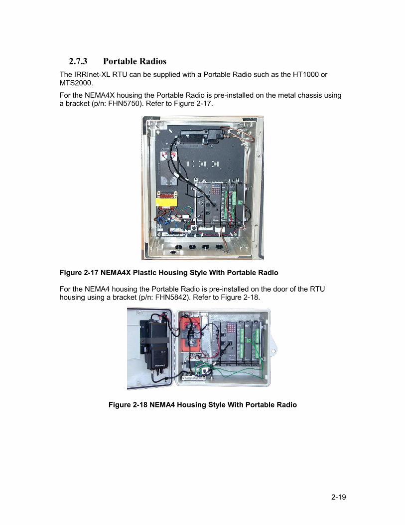
2.7.3 Portable Radios The IRRInet-XL RTU can be supplied with a Portable Radio such as the HT1000 or MTS2000. For the NEMA4X housing the Portable Radio is pre-installed on the metal chassis using a bracket (p/n: FHN5750). Refer to Figure 2-17.
Figure 2-17 NEMA4X Plastic Housing Style With Portable Radio
For the NEMA4 housing the Portable Radio is pre-installed on the door of the RTU housing using a bracket (p/n: FHN5842). Refer to Figure 2-18.
Figure 2-18 NEMA4 Housing Style With Portable Radio
2-20
Assembly Instructions: 1. Verify that the Portable Radio power cable (p/n: FKN4465) is connected to
the 'AUX' connector of the Power Supply Module. 2. Verify that the radio communication cable (FKN5953) is connected to the
radio on one end, and to the CPU module Port 3 at the other end. 3. If assembly is on the 3-slot metal chassis: attach the Portable Radio Antenna
Cable (p/n: FKN5752) to the radio, using the female adapter SMA-to-BNC (p/n: 5880384G68), and the other end to the bottom of the RTU housing enclosure.
4. If assembly is in the NEMA4 housing enclosure: attach the Portable Radio Antenna Cable (p/n: FKN4464) to the radio, using the female adapter SMA-to-SMA (p/n: 0980411L01), and the other end to the RTU housing enclosure.
Operation Turn the radio On-OFF / Volume knob to the ON position.
NNoottee:: Setting the radio volume level is insignificant. However, set the volume knob to minimum, to save battery power in case of power failure.
Removing The Portable Radio To remove the radio from the RTU proceed as follows:
1. Turn off the DC power. 2. Disconnect the DC power and antenna cable from the radio. 3. Disconnect the communication cable. 4. Remove the screws securing the radio to its mounting bracket.
Installing The Portable Radio To install the radio from the RTU proceed as follows:
1. Turn off the DC power. 2. Place the radio and secure the screw of the radio-mounting bracket to the
radio. 3. Reconnect the communication cable. 4. Reconnect the DC power and antenna cables to the radio.
2-21
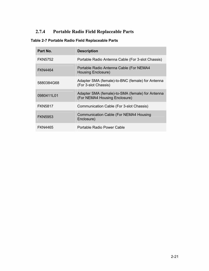
2.7.4 Portable Radio Field Replaceable Parts
Table 2-7 Portable Radio Field Replaceable Parts
Part No. Description
FKN5752 Portable Radio Antenna Cable (For 3-slot Chassis)
FKN4464 Portable Radio Antenna Cable (For NEMA4 Housing Enclosure)
5880384G68 Adapter SMA (female)-to-BNC (female) for Antenna (For 3-slot Chassis)
0980411L01 Adapter SMA (female)-to-SMA (female) for Antenna (For NEMA4 Housing Enclosure)
FKN5817 Communication Cable (For 3-slot Chassis)
FKN5953 Communication Cable (For NEMA4 Housing Enclosure)
FKN4465 Portable Radio Power Cable
2-22
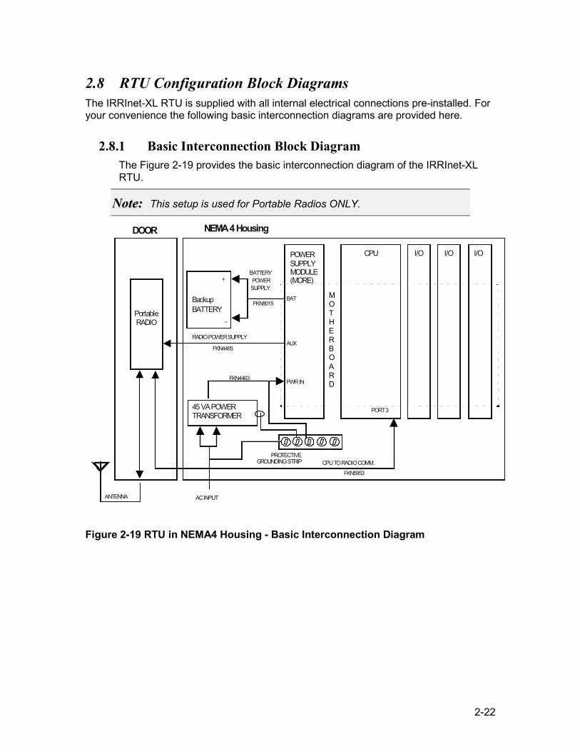
2.8 RTU Configuration Block Diagrams The IRRInet-XL RTU is supplied with all internal electrical connections pre-installed. For your convenience the following basic interconnection diagrams are provided here.
2.8.1 Basic Interconnection Block Diagram The Figure 2-19 provides the basic interconnection diagram of the IRRInet-XL RTU.
NNoottee:: This setup is used for Portable Radios ONLY.
POWER SUPPLY CPU
Backup BATTERY Portable
RADIO AUX
BAT
PORT 3
+
–
ANTENNA
PROTECTIVE GROUNDING STRIP CPU TO RADIO COMM.
RADIO POWER SUPPLY
BATTERY POWER SUPPLY FKN8015
FKN4465
FKN5953
45 VA POWER TRANSFORMER
PWR INFKN4463
AC INPUT
I/O I/O I/O DOOR NEMA 4 Housing
MO TH E R B O A R D
MODULE(MORE)
Figure 2-19 RTU in NEMA4 Housing - Basic Interconnection Diagram
2-23
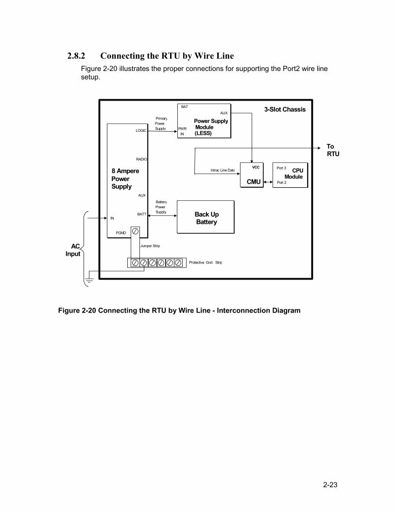
2.8.2 Connecting the RTU by Wire Line Figure 2-20 illustrates the proper connections for supporting the Port2 wire line setup.
VCC
CMU
VCC
CMU
3-Slot Chassis
Power Supply
LOGIC
RADIO
PGND
IN BATT Back UpBattery
Jumper Strip Protective Gnd Strip
Power SupplyModule
AUX BAT
PWR IN
PrimaryPowerSupply
AUX
BatteryPowerSupply
Intrac Line Data CPU Module
Port 3
Port 2
ACInput
ToRTU
8 Ampere
(LESS)
Figure 2-20 Connecting the RTU by Wire Line - Interconnection Diagram
2-24
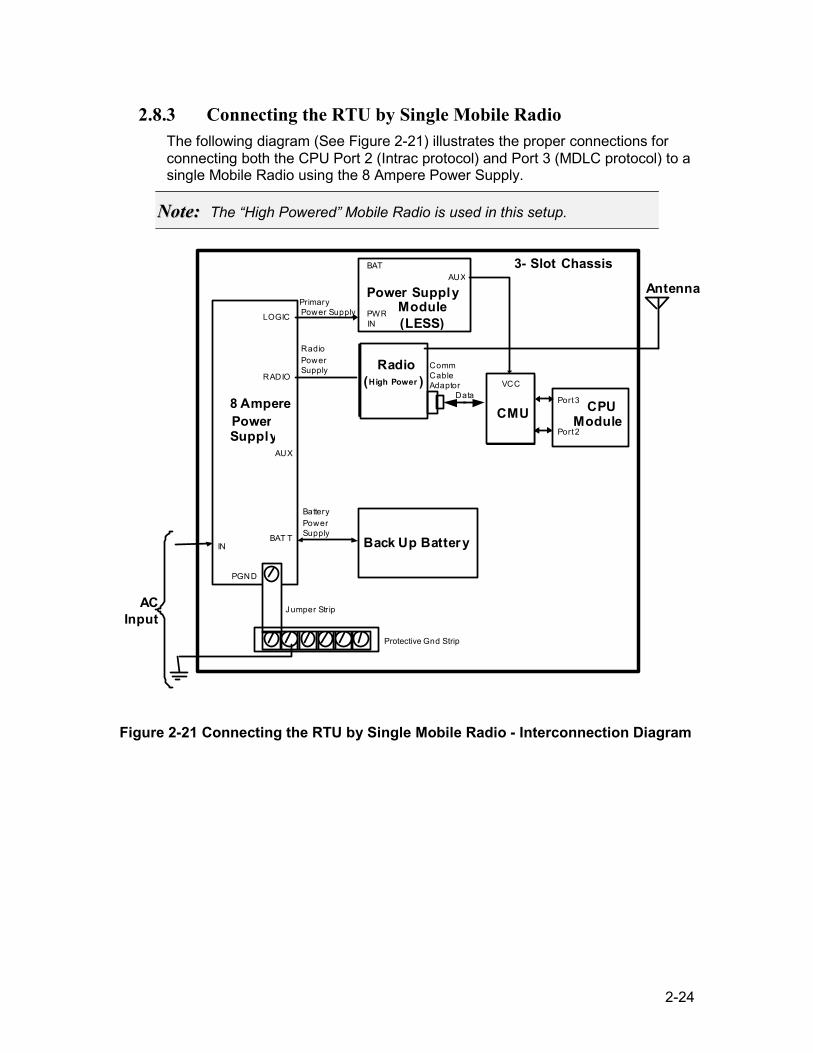
2.8.3 Connecting the RTU by Single Mobile Radio The following diagram (See Figure 2-21) illustrates the proper connections for connecting both the CPU Port 2 (Intrac protocol) and Port 3 (MDLC protocol) to a single Mobile Radio using the 8 Ampere Power Supply.
NNoottee:: The “High Powered” Mobile Radio is used in this setup.
VCC
CMU
3- Slot Chassis
AC Input
Antenna
PowerSupply
LOGIC
RADIO
PGND IN BAT T Back Up Battery
Radio(High Power )
Jumper Str ip
CPU Module
Port 3 Port 2
Data
Protective Gnd Strip
Power SupplyModule(LESS)
AUXBAT
PWRIN
Primary Power Supply
RadioPower Supply
AUX
Battery Power Supply
Comm CableAdaptor VCC
CMU8 Ampere
Figure 2-21 Connecting the RTU by Single Mobile Radio - Interconnection Diagram
2-25
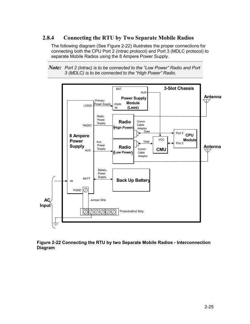
2.8.4 Connecting the RTU by Two Separate Mobile Radios The following diagram (See Figure 2-22) illustrates the proper connections for connecting both the CPU Port 2 (Intrac protocol) and Port 3 (MDLC protocol) to separate Mobile Radios using the 8 Ampere Power Supply.
NNoottee:: Port 2 (Intrac) is to be connected to the “Low Power” Radio and Port 3 (MDLC) is to be connected to the “High Power” Radio.
VCC
CMU
VCC
CMU
3-Slot Chassis
AC Input
Antenna
Power Supply
LOGIC
RADIO
PGND
INBATT Back Up Battery
Radio(High Power)
Radio(Low Power )
Jumper Strip
CPU Module
Port 3 Port 2
Data
Data
Protective Gnd Strip
Power Supply Module(Less)
AUX BAT
PWRIN
Primary Power Supply
RadioPowerSupply
AuxPowerSupplyAUX
BatteryPowerSupply
CommCableAdaptor
Antenna
CommCableAdaptor
8 Ampere
Figure 2-22 Connecting the RTU by two Separate Mobile Radios - Interconnection Diagram
2-26
2.9 Installation of Plug-in Modules and Units The RTU comprises a multi-slot I/O card cage with five vertical slots for the following plug-in modules:
• The Power Supply Module is installed in the first left-hand slot.
• The CPU Module is installed in the second slot from the left.
• The optional I/O Modules are installed in the remaining 3-slots, in accordance with the setup made in the site configuration file inside the MOSCAD ToolBox.
One of the following RTU communication units can be installed horizontally on the top of the card cage:
• CMU Module
• RS485 Adaptor
NNoottee:: All modules and units ordered are pre-installed in the factory.
2-27
2.10 Module Replacement
NNoottee:: To avoid data loss from the CPU memory during I/O Module replacement, refer to CHAPTER 8.
For details on the installation and replacement of all RTU modules, (Power Supply, CPU, Single Cable, I/O-AC, I/O-DC, CMU, or RS485 Adapter), refer to the relevant sections in this manual.
WWaarrnniinngg!! Verify that the DC power is turned off before removing or installing a module or any unit.
2.10.1 Removing the Power Supply Module To remove the module from the RTU card cage proceed as follows:
1. Turn off the DC power. 2. Disconnect all wire connections from the module. 3. Press the snap, located at the bottom of the front plastic panel, in the downward
direction and pull the module out.
2.10.2 Installing the Power Supply Module To install module in the RTU card cage proceed as follows:
1. Turn off the DC power. 2. Place the module into the first left-hand slot. 3. Slide it into the slot until the snaps click into place. 4. Reconnect all wire connections. 5. Turn on the DC power.
NNoottee:: The IRRInet-XL RTU is supplied with a transparent label card that allows the user to record the slot number and I/O connections for each module in use. For every I/O Module there is also a pre-printed user I/O Label Card. These labels are designed to be placed onto the transparent Label Card for easy reference.
2-28
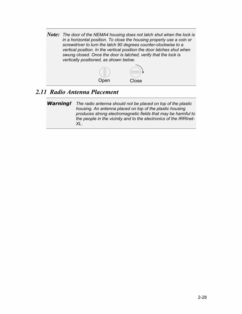
NNoottee:: The door of the NEMA4 housing does not latch shut when the lock is in a horizontal position. To close the housing properly use a coin or screwdriver to turn the latch 90 degrees counter-clockwise to a vertical position. In the vertical position the door latches shut when swung closed. Once the door is latched, verify that the lock is vertically positioned, as shown below.
Open Close
2.11 Radio Antenna Placement
WWaarrnniinngg!! The radio antenna should not be placed on top of the plastic housing. An antenna placed on top of the plastic housing produces strong electromagnetic fields that may be harmful to the people in the vicinity and to the electronics of the IRRInet-XL.
2-29
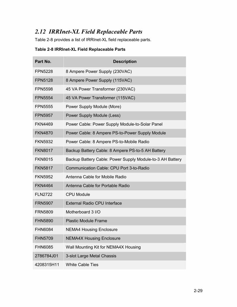
2.12 IRRInet-XL Field Replaceable Parts Table 2-8 provides a list of IRRInet-XL field replaceable parts.
Table 2-8 IRRInet-XL Field Replaceable Parts
Part No. Description
FPN5228 8 Ampere Power Supply (230VAC)
FPN5128 8 Ampere Power Supply (115VAC)
FPN5598 45 VA Power Transformer (230VAC)
FPN5554 45 VA Power Transformer (115VAC)
FPN5555 Power Supply Module (More)
FPN5957 Power Supply Module (Less)
FKN4469 Power Cable: Power Supply Module-to-Solar Panel
FKN4870 Power Cable: 8 Ampere PS-to-Power Supply Module
FKN5932 Power Cable: 8 Ampere PS-to-Mobile Radio
FKN8017 Backup Battery Cable: 8 Ampere PS-to-5 AH Battery
FKN8015 Backup Battery Cable: Power Supply Module-to-3 AH Battery
FKN5817 Communication Cable: CPU Port 3-to-Radio
FKN5952 Antenna Cable for Mobile Radio
FKN4464 Antenna Cable for Portable Radio
FLN2722 CPU Module
FRN5907 External Radio CPU Interface
FRN5809 Motherboard 3 I/O
FHN5890 Plastic Module Frame
FHN6084 NEMA4 Housing Enclosure
FHN5709 NEMA4X Housing Enclosure
FHN6085 Wall Mounting Kit for NEMA4X Housing
2786784J01 3-slot Large Metal Chassis
4208315H11 White Cable Ties
3-1
CHAPTER 3 In-box Modules
3.1 Power Supply Module
3.1.1 Power Supply Versions The following versions of the Power Supply Modules exist: 1. Less (FPN5957) – Used with Mobile Radios 2. More (FPN5555) – Used with Portable Radios The Less Power Supply Module is used with the following power sources:
1. External +12 to +16 VDC Power Supply or Solar Panel 2. 8 Ampere Power Supply
The More Power Supply Module is used with the following power sources: 3. 45 VA Main Power Transformer
3.1.2 Powering the Module
NNoottee:: The input and output circuits of the Power Supply Module are protected by on-board fuses.
External +12 to +16 VDC Power Supply or Solar Panel To power-on the IRRInet-XL RTU use power cable (p/n FKN4469A). Connect this power cable directly from the external source to the “PWR IN” of the Power Supply Module.
8 Ampere Power Supply To power-on the IRRInet-XL RTU turn the “DC OUT” Switch on the front panel of the 8 Ampere Power Supply to the ON position.
45 VA Power Transformer To power-on the IRRInet-XL RTU turn the “DC” switch on the front panel of the Power Supply Module to the ON position.
3-2
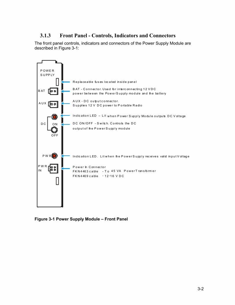
3.1.3 Front Panel - Controls, Indicators and Connectors The front panel controls, indicators and connectors of the Power Supply Module are described in Figure 3-1:
P O W E R S U PP LY
B AT
A U X
D C O N
O FF
P W R
P W R IN
B AT - C o n n ec to r. U se d fo r i n te rc on n ec ti n g 1 2 V D C p o w e r be tw e en the Po w e r S u p pl y mo d ul e an d th e ba tte ry
R e p la ce a bl e fu s es l oc a ted in si d e p an e l
A U X - D C o u tp u t c o nn ec to r. S u p pl ie s 1 2 V D C p o we r to P o rta ble R a di o
D C O N /O FF - S w i tc h. C o ntro ls the D C
o u tp u t o f th e P o w e r S u pp l y mo d ul e
In d ic a ti o n L ED . L i t w h e n th e P o w e r S u pp l y rec ei ve s val id in p u t V ol tag e
P o w e r In C on n ec to r FK N 4 46 3 c a ble - T o 4 5 VA P o w e r T ran s fo rm e r
FK N 4 46 9 c a ble - 1 2 - 1 6 V D C
In d ic a ti o n L ED – L i t w h e n P o we r S up p l y Mo du l e o u tpu ts D C V ol ta ge
Figure 3-1 Power Supply Module – Front Panel
3-3
3.1.4 Power Supply Module Field Replaceable Parts
Table 3-1 Power Supply Module Field Replaceable Parts
Part No. Description
6502069C09 F1, F2, F3: Fuse 4 Amp SB 5 x 20
6486318F01 PS Plastic Panel
FPN5957 Power Supply Module – Less
FPN5555 Power Supply Module – More
3-4
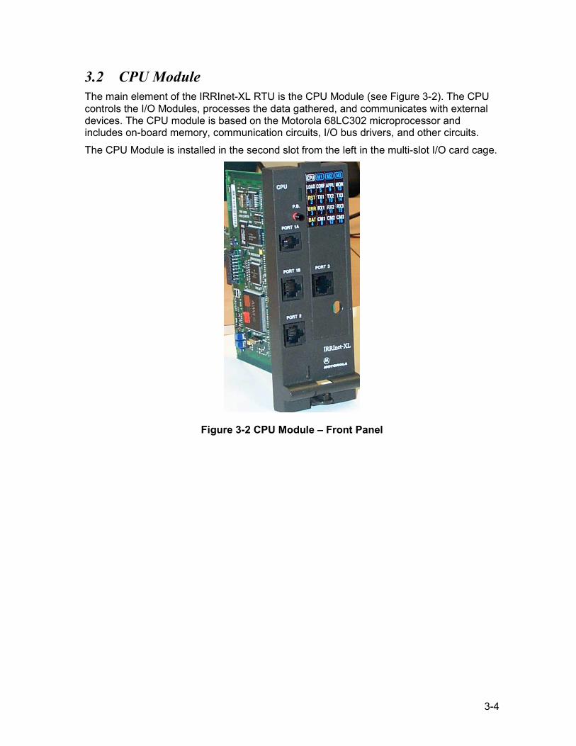
3.2 CPU Module The main element of the IRRInet-XL RTU is the CPU Module (see Figure 3-2). The CPU controls the I/O Modules, processes the data gathered, and communicates with external devices. The CPU module is based on the Motorola 68LC302 microprocessor and includes on-board memory, communication circuits, I/O bus drivers, and other circuits. The CPU Module is installed in the second slot from the left in the multi-slot I/O card cage.
Figure 3-2 CPU Module – Front Panel
3-5
3.3 Front Panel Display Controls and Connectors
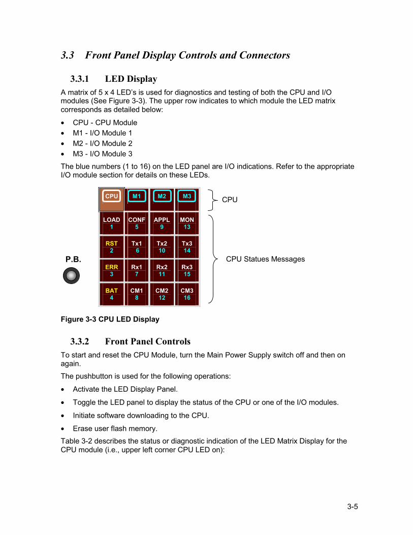
3.3.1 LED Display A matrix of 5 x 4 LED’s is used for diagnostics and testing of both the CPU and I/O modules (See Figure 3-3). The upper row indicates to which module the LED matrix corresponds as detailed below:
• CPU - CPU Module • M1 - I/O Module 1 • M2 - I/O Module 2 • M3 - I/O Module 3 The blue numbers (1 to 16) on the LED panel are I/O indications. Refer to the appropriate I/O module section for details on these LEDs.
CPU M1 M2 M3
LOAD 1
CONF 5
APPL 9
MON 13
RST 2
Tx1 6
Tx2 10
Tx3 14
ERR 3
Rx1 7
Rx2 11
Rx3 15
BAT 4
CM1 8
CM2 12
CM3 16
Figure 3-3 CPU LED Display
3.3.2 Front Panel Controls To start and reset the CPU Module, turn the Main Power Supply switch off and then on again. The pushbutton is used for the following operations:
• Activate the LED Display Panel.
• Toggle the LED panel to display the status of the CPU or one of the I/O modules.
• Initiate software downloading to the CPU.
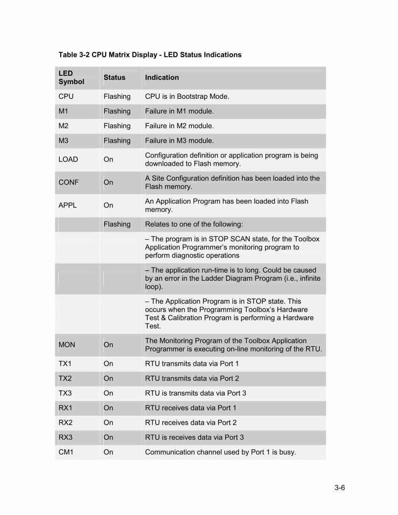
• Erase user flash memory. Table 3-2 describes the status or diagnostic indication of the LED Matrix Display for the CPU module (i.e., upper left corner CPU LED on):
CPU
CPU Statues Messages P.B.
3-6
Table 3-2 CPU Matrix Display - LED Status Indications
LED Symbol Status Indication
CPU Flashing CPU is in Bootstrap Mode.
M1 Flashing Failure in M1 module.
M2 Flashing Failure in M2 module.
M3 Flashing Failure in M3 module.
LOAD On Configuration definition or application program is being downloaded to Flash memory.
CONF On A Site Configuration definition has been loaded into the Flash memory.
APPL On An Application Program has been loaded into Flash memory.
Flashing Relates to one of the following:
– The program is in STOP SCAN state, for the Toolbox Application Programmer’s monitoring program to perform diagnostic operations
– The application run-time is to long. Could be caused by an error in the Ladder Diagram Program (i.e., infinite loop).
– The Application Program is in STOP state. This occurs when the Programming Toolbox’s Hardware Test & Calibration Program is performing a Hardware Test.
MON On The Monitoring Program of the Toolbox Application Programmer is executing on-line monitoring of the RTU.
TX1 On RTU transmits data via Port 1
TX2 On RTU transmits data via Port 2
TX3 On RTU is transmits data via Port 3
RX1 On RTU receives data via Port 1
RX2 On RTU receives data via Port 2
RX3 On RTU is receives data via Port 3
CM1 On Communication channel used by Port 1 is busy.
3-7
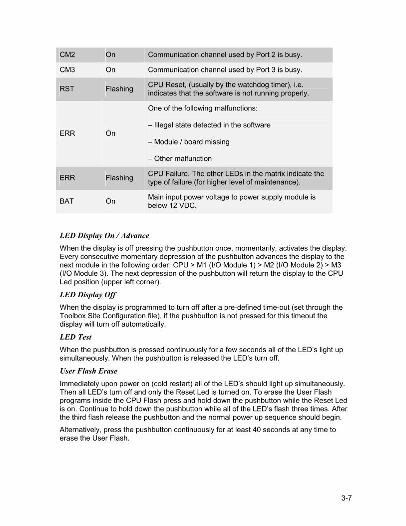
CM2 On Communication channel used by Port 2 is busy.
CM3 On Communication channel used by Port 3 is busy.
RST Flashing CPU Reset, (usually by the watchdog timer), i.e. indicates that the software is not running properly.
ERR On
One of the following malfunctions: – Illegal state detected in the software – Module / board missing – Other malfunction
ERR Flashing CPU Failure. The other LEDs in the matrix indicate the type of failure (for higher level of maintenance).
BAT On Main input power voltage to power supply module is below 12 VDC.
LED Display On / Advance When the display is off pressing the pushbutton once, momentarily, activates the display. Every consecutive momentary depression of the pushbutton advances the display to the next module in the following order: CPU > M1 (I/O Module 1) > M2 (I/O Module 2) > M3 (I/O Module 3). The next depression of the pushbutton will return the display to the CPU Led position (upper left corner).
LED Display Off When the display is programmed to turn off after a pre-defined time-out (set through the Toolbox Site Configuration file), if the pushbutton is not pressed for this timeout the display will turn off automatically.
LED Test When the pushbutton is pressed continuously for a few seconds all of the LED’s light up simultaneously. When the pushbutton is released the LED’s turn off.
User Flash Erase Immediately upon power on (cold restart) all of the LED’s should light up simultaneously. Then all LED’s turn off and only the Reset Led is turned on. To erase the User Flash programs inside the CPU Flash press and hold down the pushbutton while the Reset Led is on. Continue to hold down the pushbutton while all of the LED’s flash three times. After the third flash release the pushbutton and the normal power up sequence should begin. Alternatively, press the pushbutton continuously for at least 40 seconds at any time to erase the User Flash.
3-8
3.3.3 Software Downloading While powering on the RTU press and hold down the pushbutton. This should cause the CPU LED Display (upper left corner) to flash on / off indicating that the CPU has entered into its bootstrap mode. Now it is possible to download a system file into the CPU Flash. Connect a PC to the CPU Port 2 for downloading. If after approximately 120 seconds no bootstrap software is loaded and executed the normal power-up procedure is performed or an error message is displayed on the PC.
3.3.4 Connectors The CPU ports are designed for the following uses: PORT 1A – Data Port (RS-485) PORT 1B – Data Port (RS-232) PORT 2 – Data Port (RS-232) PORT 3 – Data Port (RS-232, Radio, or Line Connection)
NNoottee:: Ports 2 and 3 can operate simultaneously with each other and with either Port 1A or Port 1B. Ports 1A and 1B cannot work simultaneously.
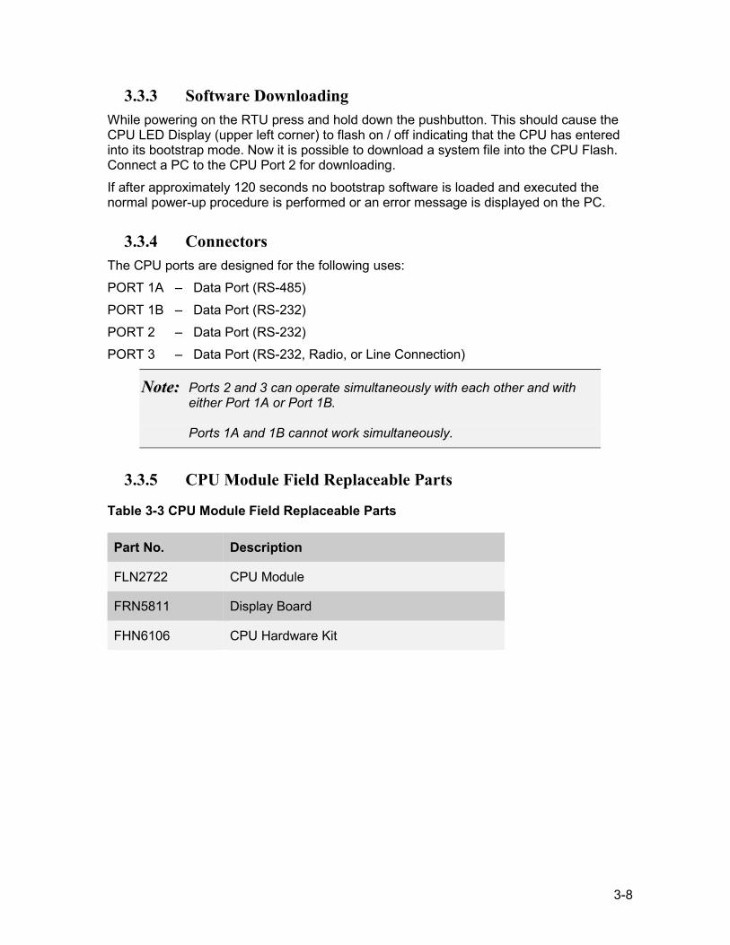
3.3.5 CPU Module Field Replaceable Parts
Table 3-3 CPU Module Field Replaceable Parts
Part No. Description
FLN2722 CPU Module
FRN5811 Display Board
FHN6106 CPU Hardware Kit
3-9
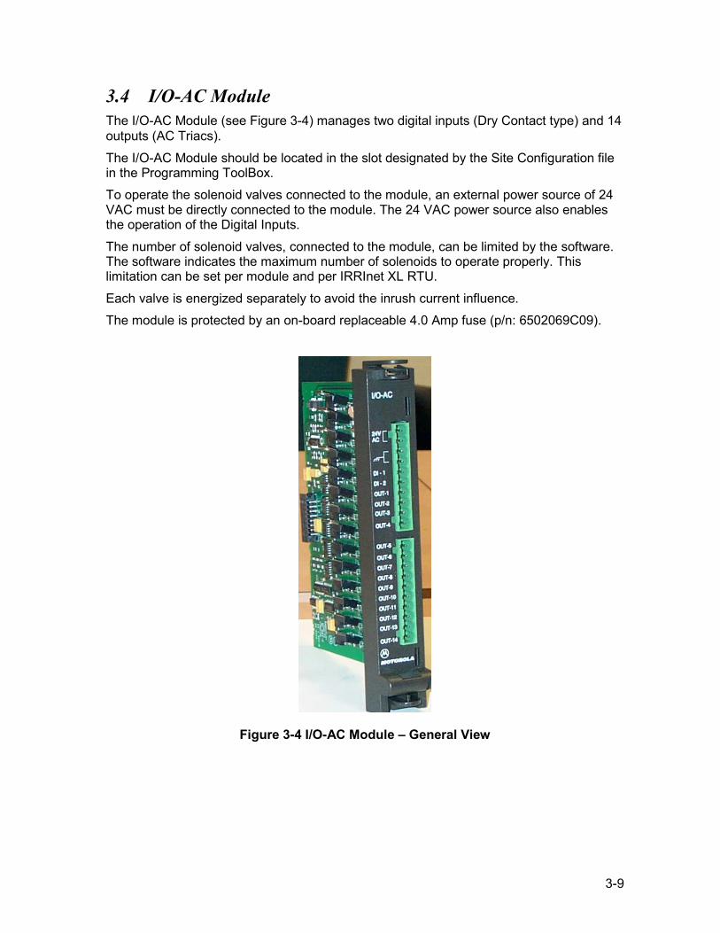
3.4 I/O-AC Module The I/O-AC Module (see Figure 3-4) manages two digital inputs (Dry Contact type) and 14 outputs (AC Triacs). The I/O-AC Module should be located in the slot designated by the Site Configuration file in the Programming ToolBox. To operate the solenoid valves connected to the module, an external power source of 24 VAC must be directly connected to the module. The 24 VAC power source also enables the operation of the Digital Inputs. The number of solenoid valves, connected to the module, can be limited by the software. The software indicates the maximum number of solenoids to operate properly. This limitation can be set per module and per IRRInet XL RTU. Each valve is energized separately to avoid the inrush current influence. The module is protected by an on-board replaceable 4.0 Amp fuse (p/n: 6502069C09).
Figure 3-4 I/O-AC Module – General View
3-10
3.4.1 Wire Connections 1. For the NEMA4 housing enclosure punch a hole in one of the perforated circles at
the bottom of the RTU housing and insert the wires through the opening. For the NEMA4X housing enclosure use the existing holes located at the bottom of the housing.
2. To operate AC Solenoids an external 24 VAC Power Transformer (75VA) must be connected to the I/O-AC Module as shown in Figure 3-5. External Transformer Connections:
3. Connect the primary inputs of the transformer to the AC Mains. 115 VAC to Black and White wires. 230 VAC to Brown and Blue wires.
4. Connect the secondary outputs of the transformer to the I/O-AC module. +VAC to pin 1 or 2 (Red wire if using Motorola option V240 or V260). -VAC to pin 3 or 4 (Green wire connected to protective ground strip if using Motorola option V240 or V260).
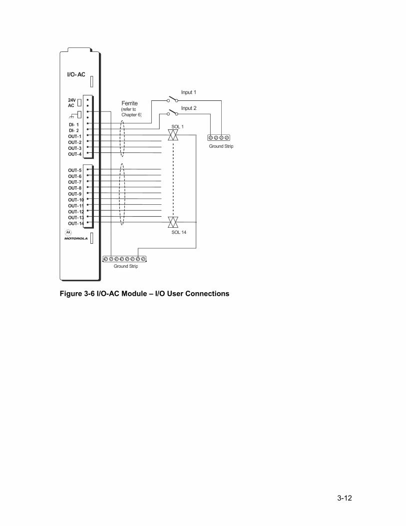
5. Connect all I/O wires to the mating connector according to your settings in the Site Configuration Program in the Programming Tool Box (see Figure 3-6). Ensure that the mating connector with connections #1 - #10 is inserted into the upper TB and that the mating connector with connections #11 - #20 is inserted into the lower TB of the module.
NNoottee:: To comply with CE and FCC standards a ferrite (p/n: FLN9448) must be clamped onto the I/O wires. Refer to CHAPTER 6 for assembly instructions.
6...Use the ID label card to record the TB pin connections.

3-11
I/O - AC
24V AC
OUT - 5 OUT - 6 OUT - 7 OUT - 8 OUT - 9 OUT - 10 OUT - 11 OUT - 12 OUT - 13 OUT - 14
DI - 1 DI - 2 OUT - 1 OUT - 2 OUT - 3 OUT - 4
Ground Strip
Externa l 75VA Tr ansformer Black or Brown (Hot)
White or Blue (Neutral)Black
115 or 230 V ACFrom Power Supply
NOT ES:1. If us ing 45 VA Main Power T ransformer connect to AC Line source
us ing Line Connector on Chassis . 2. In the NEMA4 hous ing enclosure there is no designated location for
the I/O - AC 24 V AC Power T ransformer.
Green
Green Red
Tied to Tra nsfor mer Housing
GND W ire FKN8037
Figure 3-5 I/O-AC Module – External 75 VA Transformer User Connections
3-12
I/O-AC
24VAC
OUT-5OUT-6OUT-7OUT-8OUT-9OUT-10OUT-11OUT-12OUT-13OUT-14
DI- 1DI- 2OUT-1OUT-2OUT-3OUT-4
Ferrite(refer toChapter 6)
Ground Strip
Ground Strip
SOL 1
SOL 14
Input 2
Input 1
Figure 3-6 I/O-AC Module – I/O User Connections
3-13
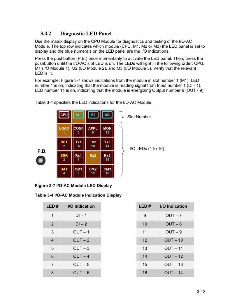
3.4.2 Diagnostic LED Panel Use the matrix display on the CPU Module for diagnostics and testing of the I/O-AC Module. The top row indicates which module (CPU, M1, M2 or M3) the LED panel is set to display and the blue numerals on the LED panel are the I/O indications. Press the pushbutton (P.B.) once momentarily to activate the LED panel. Then, press the pushbutton until the I/O-AC slot LED is on. The LEDs will light in the following order: CPU, M1 (I/O Module 1), M2 (I/O Module 2), and M3 (I/O Module 3). Verify that the relevant LED is lit. For example; Figure 3-7 shows indications from the module in slot number 1 (M1). LED number 1 is on, indicating that the module is reading signal from Input number 1 (DI - 1). LED number 11 is on, indicating that the module is energizing Output number 9 (OUT - 9) Table 3-4 specifies the LED indications for the I/O-AC Module.
CPU M1 M2 M3
LOAD 1
CONF 5
APPL 9
MON 13
RST 2
Tx1 6
Tx2 10
Tx3 14
ERR 3
Rx1 7
Rx2 11
Rx3 15
BAT 4
CM1 8
CM2 12
CM3 16
Figure 3-7 I/O-AC Module LED Display
Table 3-4 I/O-AC Module Indication Display
LED # I/O Indication LED # I/O Indication
1 DI – 1 9 OUT – 7
2 DI – 2 10 OUT – 8
3 OUT – 1 11 OUT – 9
4 OUT – 2 12 OUT – 10
5 OUT – 3 13 OUT – 11
6 OUT – 4 14 OUT – 12
7 OUT – 5 15 OUT – 13
8 OUT – 6 16 OUT – 14
Slot Number
I/O LEDs (1 to 16) P.B.
3-14
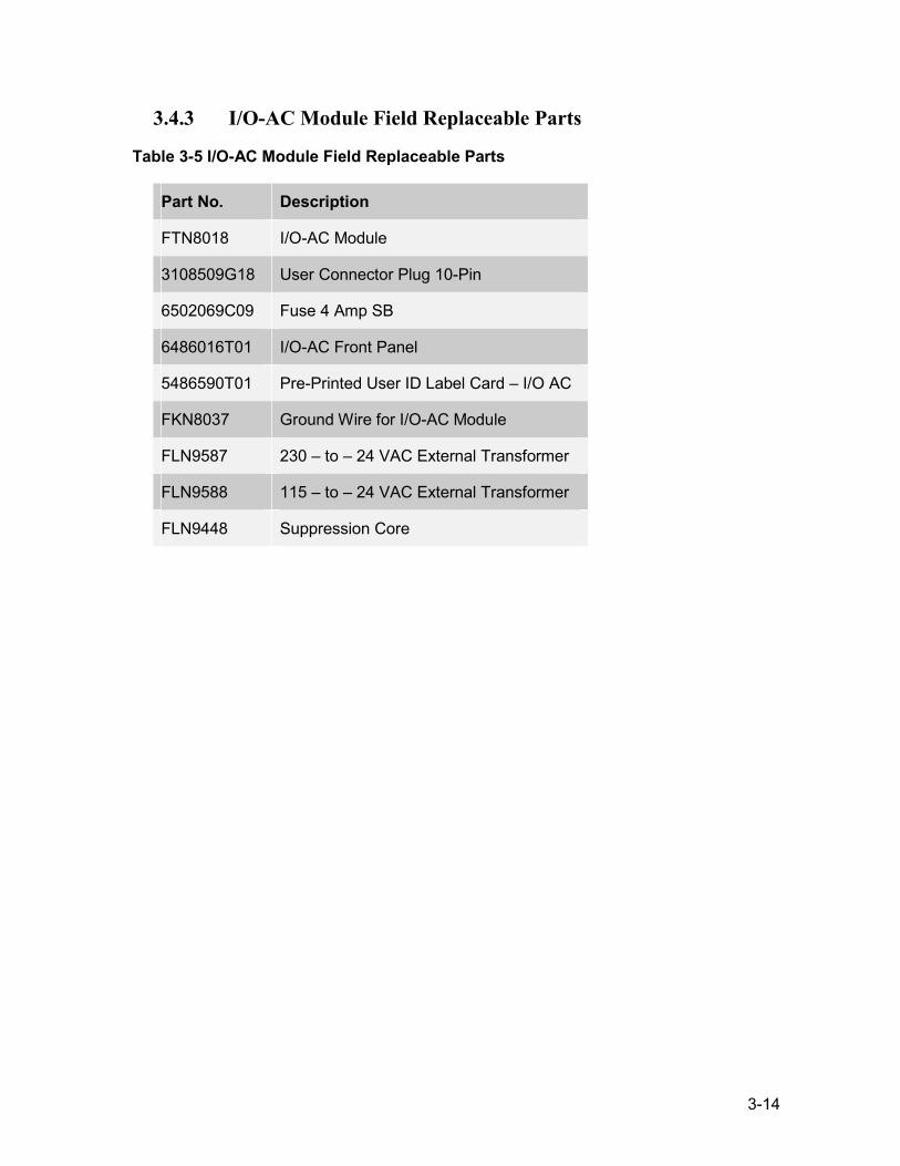
3.4.3 I/O-AC Module Field Replaceable Parts
Table 3-5 I/O-AC Module Field Replaceable Parts
Part No. Description
FTN8018 I/O-AC Module
3108509G18 User Connector Plug 10-Pin
6502069C09 Fuse 4 Amp SB
6486016T01 I/O-AC Front Panel
5486590T01 Pre-Printed User ID Label Card – I/O AC
FKN8037 Ground Wire for I/O-AC Module
FLN9587 230 – to – 24 VAC External Transformer
FLN9588 115 – to – 24 VAC External Transformer
FLN9448 Suppression Core
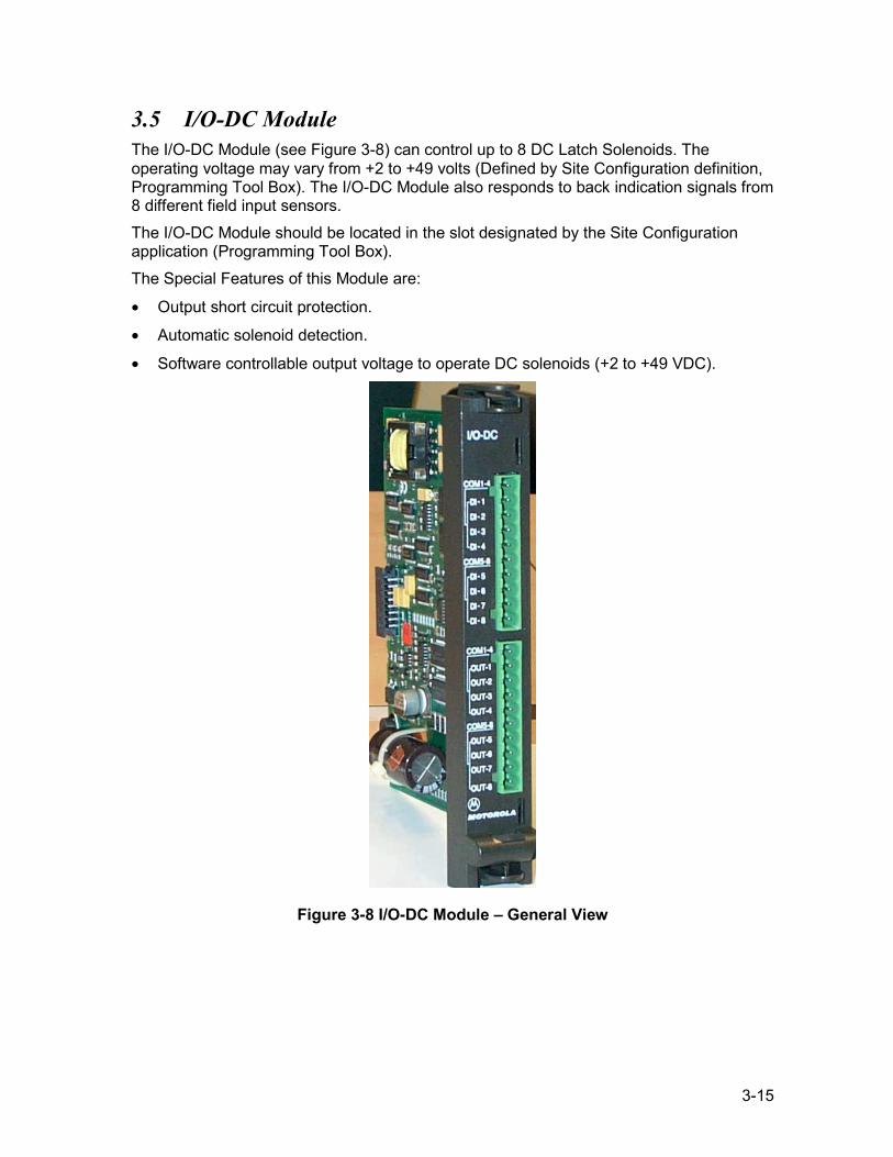
3-15
3.5 I/O-DC Module The I/O-DC Module (see Figure 3-8) can control up to 8 DC Latch Solenoids. The operating voltage may vary from +2 to +49 volts (Defined by Site Configuration definition, Programming Tool Box). The I/O-DC Module also responds to back indication signals from 8 different field input sensors. The I/O-DC Module should be located in the slot designated by the Site Configuration application (Programming Tool Box). The Special Features of this Module are:
• Output short circuit protection.
• Automatic solenoid detection.
• Software controllable output voltage to operate DC solenoids (+2 to +49 VDC).
Figure 3-8 I/O-DC Module – General View
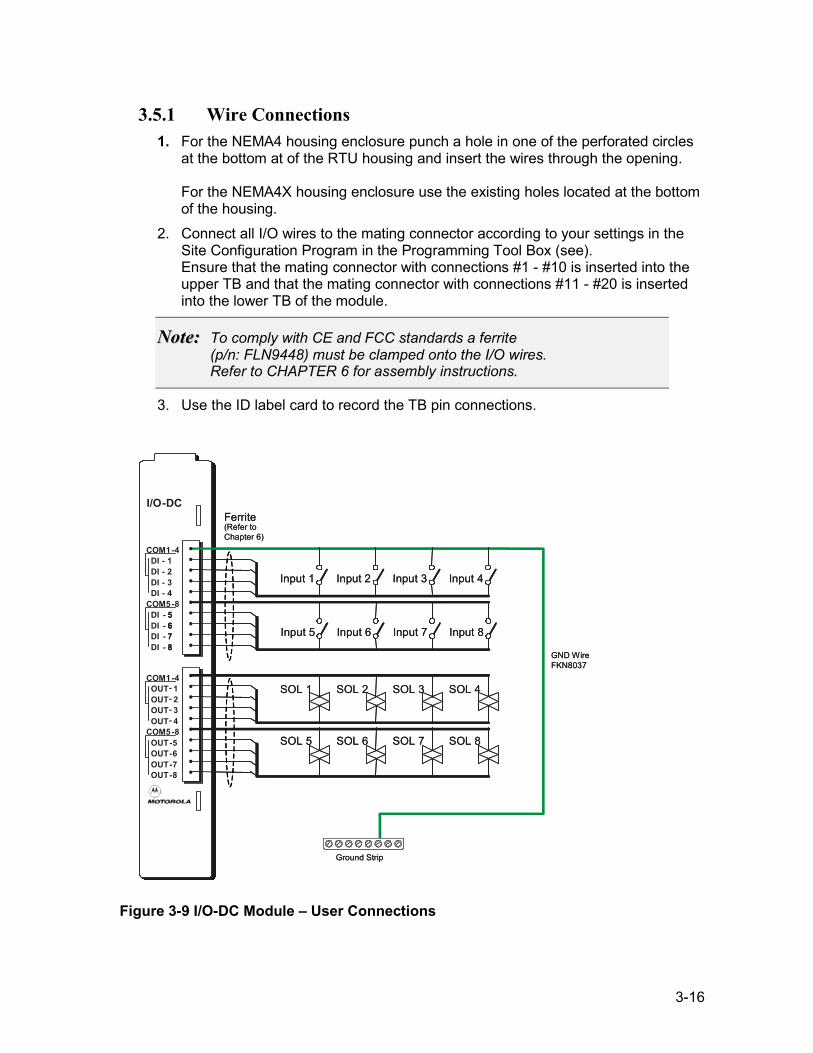
3-16
3.5.1 Wire Connections 1. For the NEMA4 housing enclosure punch a hole in one of the perforated circles
at the bottom at of the RTU housing and insert the wires through the opening. For the NEMA4X housing enclosure use the existing holes located at the bottom of the housing.
2. Connect all I/O wires to the mating connector according to your settings in the Site Configuration Program in the Programming Tool Box (see). Ensure that the mating connector with connections #1 - #10 is inserted into the upper TB and that the mating connector with connections #11 - #20 is inserted into the lower TB of the module.
NNoottee:: To comply with CE and FCC standards a ferrite (p/n: FLN9448) must be clamped onto the I/O wires. Refer to CHAPTER 6 for assembly instructions.
3. Use the ID label card to record the TB pin connections.
Figure 3-9 I/O-DC Module – User Connections
I/O-DC
COM1 -4OUT- 1OUT- 2OUT- 3OUT- 4
COM5 -8OUT-5OUT-6OUT-7OUT-8
COM1 -4DI - 1DI - 2DI - 3DI - 4
COM5 -8DI -DI -DI -DI -
5678
5678
Input 1
SOL 1
SOL 5
Input 5
Input 2
SOL 2
SOL 6
Input 6
Input 3
SOL 3
SOL 7
Input 7
Input 4
SOL 4
SOL 8
Input 8
Ferrite(Refer toChapter 6)
Ground Strip
GND Wire FKN8037
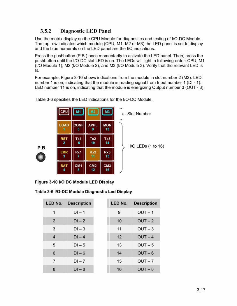
3-17
3.5.2 Diagnostic LED Panel Use the matrix display on the CPU Module for diagnostics and testing of I/O-DC Module. The top row indicates which module (CPU, M1, M2 or M3) the LED panel is set to display and the blue numerals on the LED panel are the I/O indications. Press the pushbutton (P.B.) once momentarily to activate the LED panel. Then, press the pushbutton until the I/O-DC slot LED is on. The LEDs will light in following order: CPU, M1 (I/O Module 1), M2 (I/O Module 2), and M3 (I/O Module 3). Verify that the relevant LED is lit. For example; Figure 3-10 shows indications from the module in slot number 2 (M2). LED number 1 is on, indicating that the module is reading signal from Input number 1 (DI - 1). LED number 11 is on, indicating that the module is energizing Output number 3 (OUT - 3) Table 3-6 specifies the LED indications for the I/O-DC Module.
CPU M1 M2 M3
LOAD 1
CONF 5
APPL 9
MON 13
RST 2
Tx1 6
Tx2 10
Tx3 14
ERR 3
Rx1 7
Rx2 11
Rx3 15
BAT 4
CM1 8
CM2 12
CM3 16
Figure 3-10 I/O DC Module LED Display
Table 3-6 I/O-DC Module Diagnostic Led Display
LED No. Description LED No. Description
1 DI – 1 9 OUT – 1
2 DI – 2 10 OUT – 2
3 DI – 3 11 OUT – 3
4 DI – 4 12 OUT – 4
5 DI – 5 13 OUT – 5
6 DI – 6 14 OUT – 6
7 DI – 7 15 OUT – 7
8 DI – 8 16 OUT – 8
Slot Number
I/O LEDs (1 to 16) P.B.
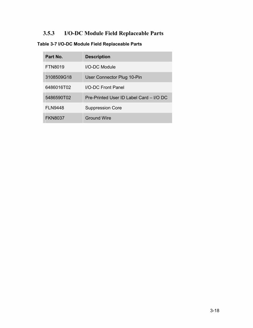
3-18
3.5.3 I/O-DC Module Field Replaceable Parts
Table 3-7 I/O-DC Module Field Replaceable Parts
Part No. Description
FTN8019 I/O-DC Module
3108509G18 User Connector Plug 10-Pin
6486016T02 I/O-DC Front Panel
5486590T02 Pre-Printed User ID Label Card – I/O DC
FLN9448 Suppression Core
FKN8037 Ground Wire
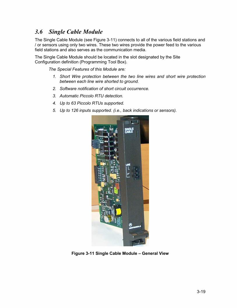
3-19
3.6 Single Cable Module The Single Cable Module (see Figure 3-11) connects to all of the various field stations and / or sensors using only two wires. These two wires provide the power feed to the various field stations and also serves as the communication media. The Single Cable Module should be located in the slot designated by the Site Configuration definition (Programming Tool Box).
The Special Features of this Module are: 1. Short Wire protection between the two line wires and short wire protection
between each line wire shorted to ground. 2. Software notification of short circuit occurrence. 3. Automatic Piccolo RTU detection.
4. Up to 63 Piccolo RTUs supported. 5. Up to 126 inputs supported. (i.e., back indications or sensors).
Figure 3-11 Single Cable Module – General View
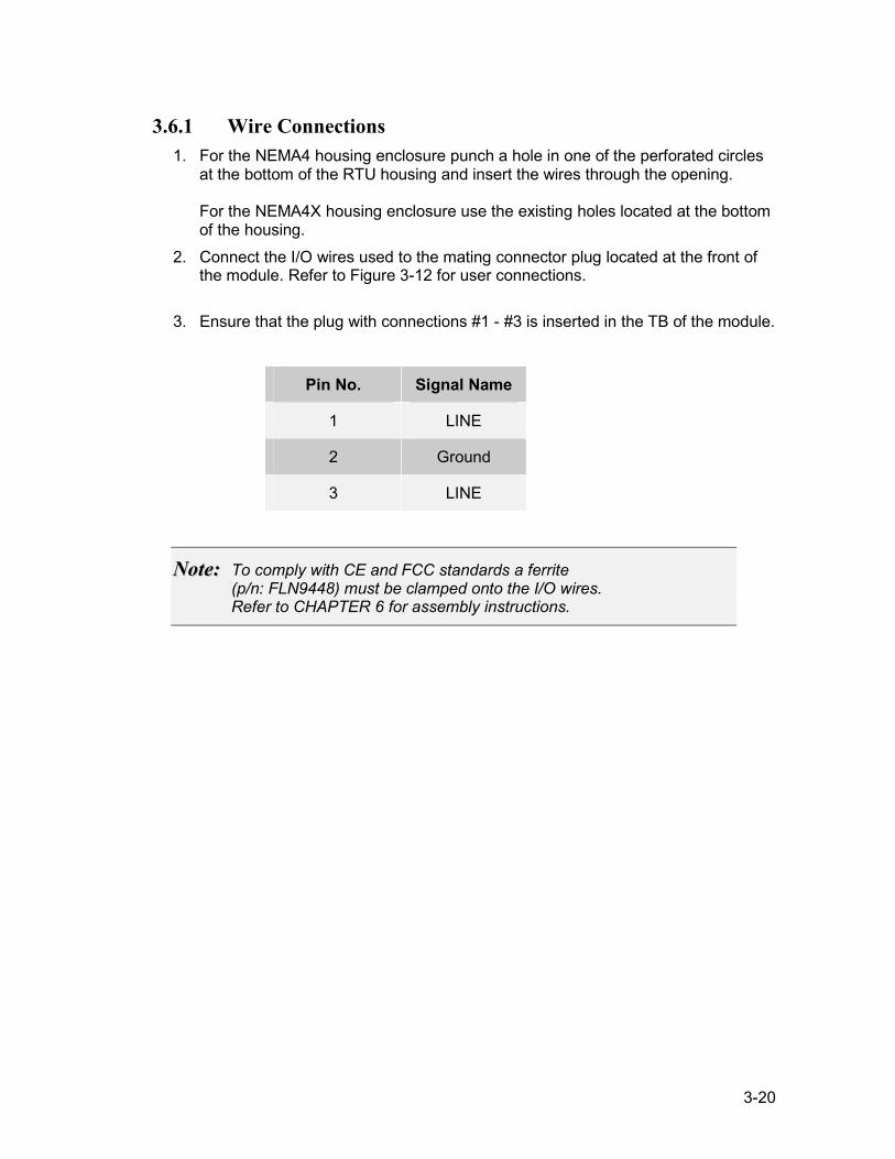
3-20
3.6.1 Wire Connections 1. For the NEMA4 housing enclosure punch a hole in one of the perforated circles
at the bottom of the RTU housing and insert the wires through the opening. For the NEMA4X housing enclosure use the existing holes located at the bottom of the housing.
2. Connect the I/O wires used to the mating connector plug located at the front of the module. Refer to Figure 3-12 for user connections.
3. Ensure that the plug with connections #1 - #3 is inserted in the TB of the module.
Pin No. Signal Name
1 LINE
2 Ground
3 LINE
NNoottee:: To comply with CE and FCC standards a ferrite (p/n: FLN9448) must be clamped onto the I/O wires. Refer to CHAPTER 6 for assembly instructions.
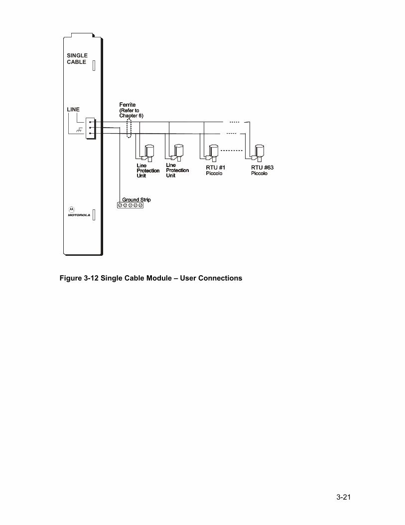
3-21
Figure 3-12 Single Cable Module – User Connections
SINGLECABLE
LINEFerrite(Refer toChapter 6)
Ground Strip
SINGLECABLE
LINE
RTU #1Piccolo
RTU #63Piccolo
Ferrite(Refer toChapter 6)
LineProtectionUnit
LineProtectionUnit
Ground Strip
LineProtectionUnit
LineProtectionUnit
SINGLECABLE
LINEFerrite(Refer toChapter 6)
Ground Strip
SINGLECABLE
LINE
RTU #1Piccolo
RTU #63Piccolo
RTU #1Piccolo
RTU #63Piccolo
Ferrite(Refer toChapter 6)
LineProtectionUnit
LineProtectionUnit
LineProtectionUnit
LineProtectionUnit
Ground Strip
LineProtectionUnit
LineProtectionUnit
LineProtectionUnit
LineProtectionUnit
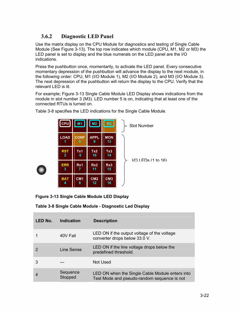
3-22
3.6.2 Diagnostic LED Panel Use the matrix display on the CPU Module for diagnostics and testing of Single Cable Module (See Figure 3-13). The top row indicates which module (CPU, M1, M2 or M3) the LED panel is set to display and the blue numerals on the LED panel are the I/O indications. Press the pushbutton once, momentarily, to activate the LED panel. Every consecutive momentary depression of the pushbutton will advance the display to the next module, in the following order: CPU, M1 (I/O Module 1), M2 (I/O Module 2), and M3 (I/O Module 3). The next depression of the pushbutton will return the display to the CPU. Verify that the relevant LED is lit. For example; Figure 3-13 Single Cable Module LED Display shows indications from the module in slot number 3 (M3). LED number 5 is on, indicating that at least one of the connected RTUs is turned on. Table 3-8 specifies the LED indications for the Single Cable Module.
CPU M1 M2 M3
LOAD 1
CONF 5
APPL 9
MON 13
RST 2
Tx1 6
Tx2 10
Tx3 14
ERR 3
Rx1 7
Rx2 11
Rx3 15
BAT 4
CM1 8
CM2 12
CM3 16
Figure 3-13 Single Cable Module LED Display
Table 3-8 Single Cable Module - Diagnostic Led Display
LED No. Indication Description
1 40V Fail LED ON if the output voltage of the voltage converter drops below 33.0 V.
2 Line Sense LED ON if the line voltage drops below the predefined threshold.
3 --- Not Used
4 Sequence Stopped
LED ON when the Single Cable Module enters into Test Mode and pseudo-random sequence is not o u t p u t t e d t o t h e l i n e d r i v e r . t
Slot Number
I/O LEDs (1 to 16)
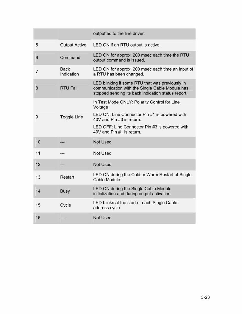
3-23
5 Output Active LED ON if an RTU output is active.
6 Command LED ON for approx. 200 msec each time the RTU output command is issued.
7 Back Indication
LED ON for approx. 200 msec each time an input of a RTU has been changed.
8 RTU Fail LED blinking if some RTU that was previously in communication with the Single Cable Module has stopped sending its back indication status report.
9 Toggle Line
In Test Mode ONLY: Polarity Control for Line Voltage LED ON: Line Connector Pin #1 is powered with 40V and Pin #3 is return. LED OFF: Line Connector Pin #3 is powered with 40V and Pin #1 is return.
10 --- Not Used
11 --- Not Used
12 --- Not Used
13 Restart LED ON during the Cold or Warm Restart of Single Cable Module.
14 Busy LED ON during the Single Cable Module initialization and during output activation.
15 Cycle LED blinks at the start of each Single Cable address cycle.
16 --- Not Used
outputted to the line driver.
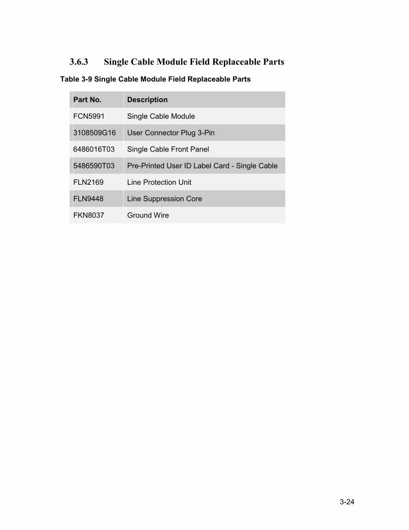
3-24
3.6.3 Single Cable Module Field Replaceable Parts
Table 3-9 Single Cable Module Field Replaceable Parts
Part No. Description
FCN5991 Single Cable Module
3108509G16 User Connector Plug 3-Pin
6486016T03 Single Cable Front Panel
5486590T03 Pre-Printed User ID Label Card - Single Cable
FLN2169 Line Protection Unit
FLN9448 Line Suppression Core
FKN8037 Ground Wire
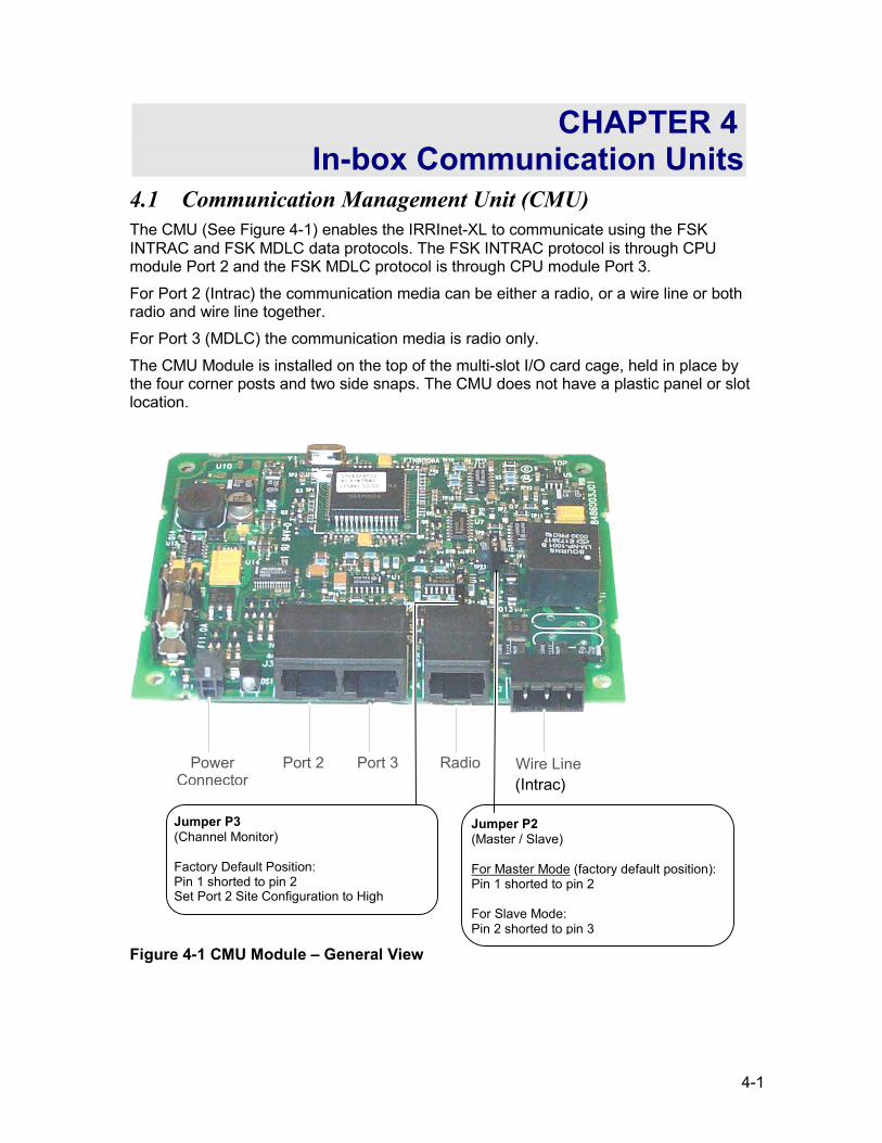
4-1
CHAPTER 4 In-box Communication Units
4.1 Communication Management Unit (CMU) The CMU (See Figure 4-1) enables the IRRInet-XL to communicate using the FSK INTRAC and FSK MDLC data protocols. The FSK INTRAC protocol is through CPU module Port 2 and the FSK MDLC protocol is through CPU module Port 3. For Port 2 (Intrac) the communication media can be either a radio, or a wire line or both radio and wire line together. For Port 3 (MDLC) the communication media is radio only. The CMU Module is installed on the top of the multi-slot I/O card cage, held in place by the four corner posts and two side snaps. The CMU does not have a plastic panel or slot location.
PowerConnector
Port 2 Port 3 Radio Wire Line
Figure 4-1 CMU Module – General View
Jumper P2 (Master / Slave) For Master Mode (factory default position): Pin 1 shorted to pin 2 For Slave Mode: Pin 2 shorted to pin 3
Jumper P3 (Channel Monitor) Factory Default Position: Pin 1 shorted to pin 2 Set Port 2 Site Configuration to High
(Intrac)
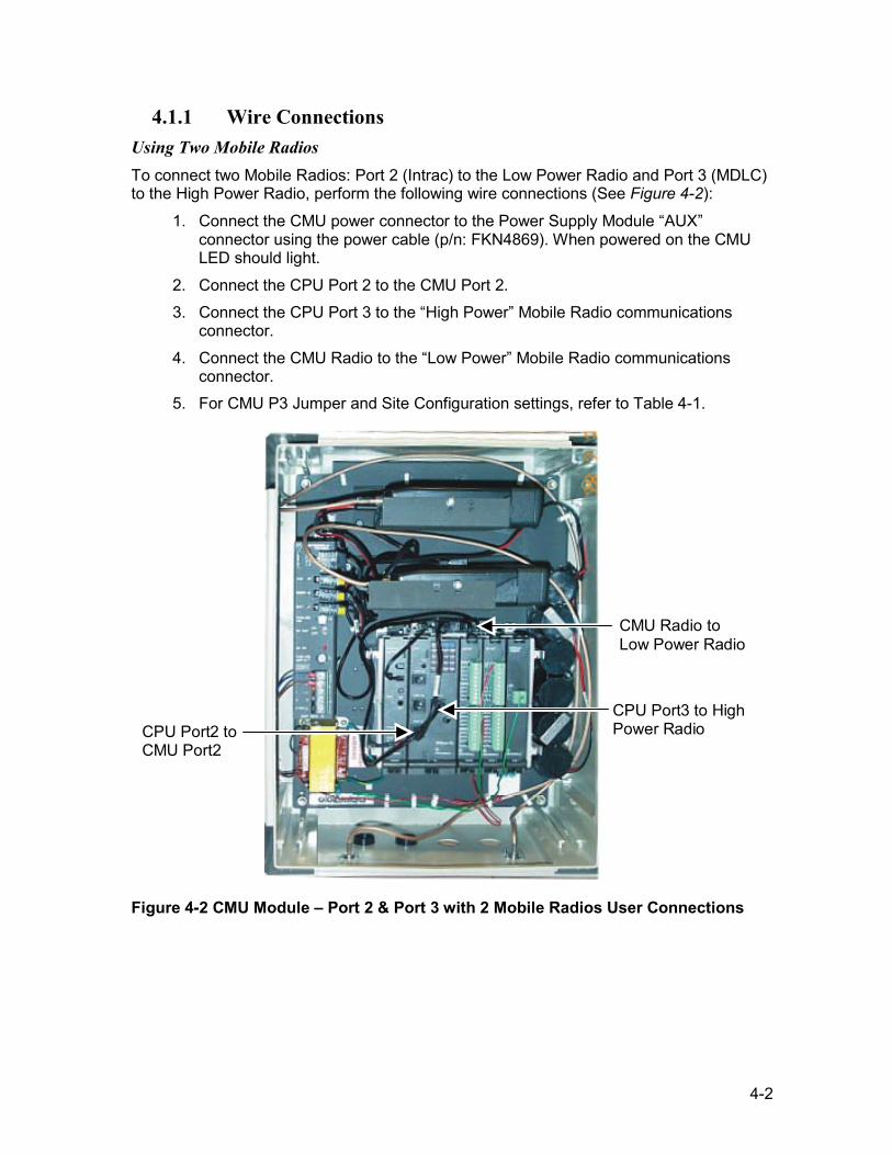
4-2
4.1.1 Wire Connections Using Two Mobile Radios To connect two Mobile Radios: Port 2 (Intrac) to the Low Power Radio and Port 3 (MDLC) to the High Power Radio, perform the following wire connections (See Figure 4-2):
1. Connect the CMU power connector to the Power Supply Module “AUX” connector using the power cable (p/n: FKN4869). When powered on the CMU LED should light.
2. Connect the CPU Port 2 to the CMU Port 2. 3. Connect the CPU Port 3 to the “High Power” Mobile Radio communications
connector. 4. Connect the CMU Radio to the “Low Power” Mobile Radio communications
connector. 5. For CMU P3 Jumper and Site Configuration settings, refer to Table 4-1.
CPU Port2 to CMU Port2
CMU Radio to Low Power Radio
CPU Port3 to High Power Radio
Figure 4-2 CMU Module – Port 2 & Port 3 with 2 Mobile Radios User Connections
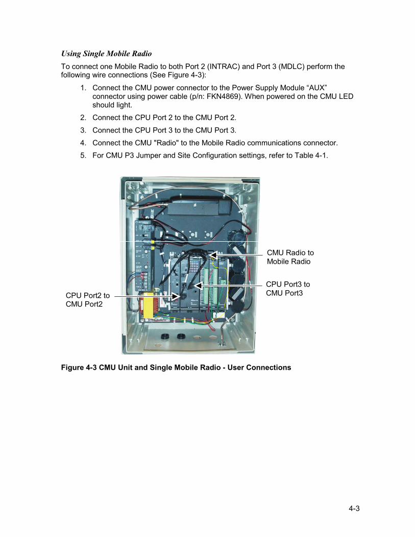
4-3
Using Single Mobile Radio To connect one Mobile Radio to both Port 2 (INTRAC) and Port 3 (MDLC) perform the following wire connections (See Figure 4-3):
1. Connect the CMU power connector to the Power Supply Module “AUX” connector using power cable (p/n: FKN4869). When powered on the CMU LED should light.
2. Connect the CPU Port 2 to the CMU Port 2. 3. Connect the CPU Port 3 to the CMU Port 3. 4. Connect the CMU "Radio" to the Mobile Radio communications connector. 5. For CMU P3 Jumper and Site Configuration settings, refer to Table 4-1.
CPU Port2 to CMU Port2
CMU Radio to Mobile Radio
CPU Port3 to CMU Port3
Figure 4-3 CMU Unit and Single Mobile Radio - User Connections
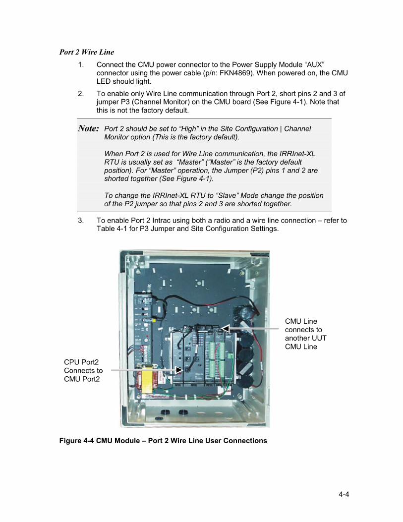
4-4
Port 2 Wire Line 1. Connect the CMU power connector to the Power Supply Module “AUX”
connector using the power cable (p/n: FKN4869). When powered on, the CMU LED should light.
2. To enable only Wire Line communication through Port 2, short pins 2 and 3 of jumper P3 (Channel Monitor) on the CMU board (See Figure 4-1). Note that this is not the factory default.
NNoottee:: Port 2 should be set to “High” in the Site Configuration | Channel Monitor option (This is the factory default). When Port 2 is used for Wire Line communication, the IRRInet-XL RTU is usually set as “Master” (“Master” is the factory default position). For “Master” operation, the Jumper (P2) pins 1 and 2 are shorted together (See Figure 4-1). To change the IRRInet-XL RTU to “Slave” Mode change the position of the P2 jumper so that pins 2 and 3 are shorted together.
3. To enable Port 2 Intrac using both a radio and a wire line connection – refer to Table 4-1 for P3 Jumper and Site Configuration Settings.
CPU Port2 Connects to CMU Port2
CMU Line connects to another UUT CMU Line
Figure 4-4 CMU Module – Port 2 Wire Line User Connections
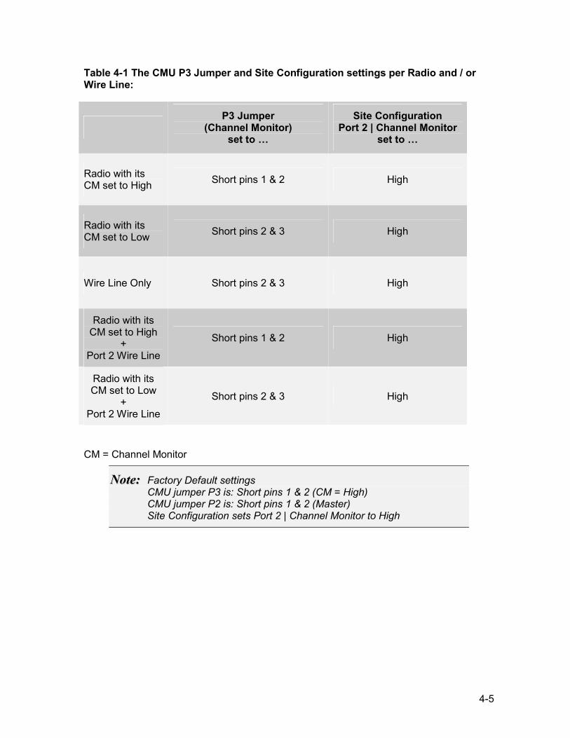
4-5
Table 4-1 The CMU P3 Jumper and Site Configuration settings per Radio and / or Wire Line:
P3 Jumper
(Channel Monitor) set to …
Site Configuration Port 2 | Channel Monitor
set to …
Radio with its CM set to High Short pins 1 & 2 High
Radio with its CM set to Low Short pins 2 & 3 High
Wire Line Only Short pins 2 & 3 High
Radio with its CM set to High
+ Port 2 Wire Line
Short pins 1 & 2 High
Radio with its CM set to Low
+ Port 2 Wire Line
Short pins 2 & 3 High
CM = Channel Monitor
NNoottee:: Factory Default settings CMU jumper P3 is: Short pins 1 & 2 (CM = High) CMU jumper P2 is: Short pins 1 & 2 (Master) Site Configuration sets Port 2 | Channel Monitor to High
4-6
4.1.2 Removal and Installation
WWaarrnniinngg!! Before removing or installing the unit verify that the DC power is off.
NNoottee:: To preserve the data inside the CPU Module RAM while the RTU is powered off refer to CHAPTER 8.
Removing the CMU Module To remove a CMU Module from the RTU proceed as follows:
1. Turn off the DC power. 2. Disconnect all cables attached to the CMU Module. 3. Remove the module by pressing the side snaps down and pulling the module up.
Installing the CMU Module To install a CMU Module in the RTU proceed as follows:
1. Turn off the DC power. 2. Place the module on the top of the multi-slot I/O card cage in alignment with the
4 corner posts. 3. Press the module into place until the two-side snaps lock the module in place. 4. Reconnect the modules power cable and various communications cables
according to the user connections shown in Figure 4-2, Figure 4-3 and Figure 4-4.
4.1.3 Diagnostic LED Panel The matrix of 5 x 4 LED’s located on the CPU Module is used for diagnostics and testing of the CPU and I/O Modules. If the CMU is operating properly then the appropriate Port 2 and Port 3 LEDs will light up during transmission and reception.
4.1.4 Setting the LED Display to the Relevant Module For CMU operation set the led matrix to display CPU operations. This is done by depressing the pushbutton on the CPU Module until the “CPU” LED is lit (See
4-7
Front Panel Display Controls and Connectors paragraph 3.3. Table 4-2 CMU Diagnostic Led Display describes the functions of the diagnostic LEDs when set to the CPU Module (i.e., the “CPU” led in the top row is on).
Table 4-2 CMU Diagnostic Led Display
LED No. Description
10 Port 2 Transmission or Reception
11 Port 2 Transmission or Reception
12 Port 2 Transmission or Reception
14 Port 3 Transmission or Reception
15 Port 3 Transmission or Reception
16 Port 3 Transmission or Reception
4.1.5 CMU Unit Field Replaceable Parts
Table 4-3 CMU Unit Field Replaceable Parts
Part No. Description
FLN2880 CMU Unit
3108509G16 User Connector Plug 3-Pin
6502069C06 Fuse 1Amp 250V SB 5 x 20 mm
5486773J01 CMU Label
GLN7306 Rubber Sealing Plug RJ45 Connector
FKN4869 Power Cable for CMU
0984181L01 2 Pin Plastic Jumper Header
FKN1648 Communication Cable Kit
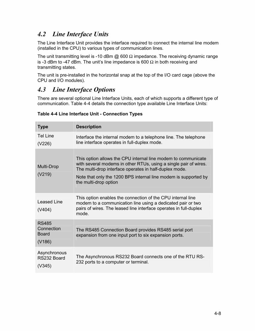
4-8
4.2 Line Interface Units The Line Interface Unit provides the interface required to connect the internal line modem (installed in the CPU) to various types of communication lines.
The unit transmitting level is -10 dBm @ 600 Ω impedance. The receiving dynamic range is -3 dBm to -47 dBm. The unit’s line impedance is 600 Ω in both receiving and transmitting states. The unit is pre-installed in the horizontal snap at the top of the I/O card cage (above the CPU and I/O modules).
4.3 Line Interface Options There are several optional Line Interface Units, each of which supports a different type of communication. Table 4-4 details the connection type available Line Interface Units:
Table 4-4 Line Interface Unit - Connection Types
Type Description
Tel Line (V226)
Interface the internal modem to a telephone line. The telephone line interface operates in full-duplex mode.
Multi-Drop (V219)
This option allows the CPU internal line modem to communicate with several modems in other RTUs, using a single pair of wires. The multi-drop interface operates in half-duplex mode. Note that only the 1200 BPS internal line modem is supported by the multi-drop option
Leased Line (V404)
This option enables the connection of the CPU internal line modem to a communication line using a dedicated pair or two pairs of wires. The leased line interface operates in full-duplex mode.
RS485 Connection Board (V186)
The RS485 Connection Board provides RS485 serial port expansion from one input port to six expansion ports.
Asynchronous RS232 Board (V345)
The Asynchronous RS232 Board connects one of the RTU RS-232 ports to a computer or terminal.
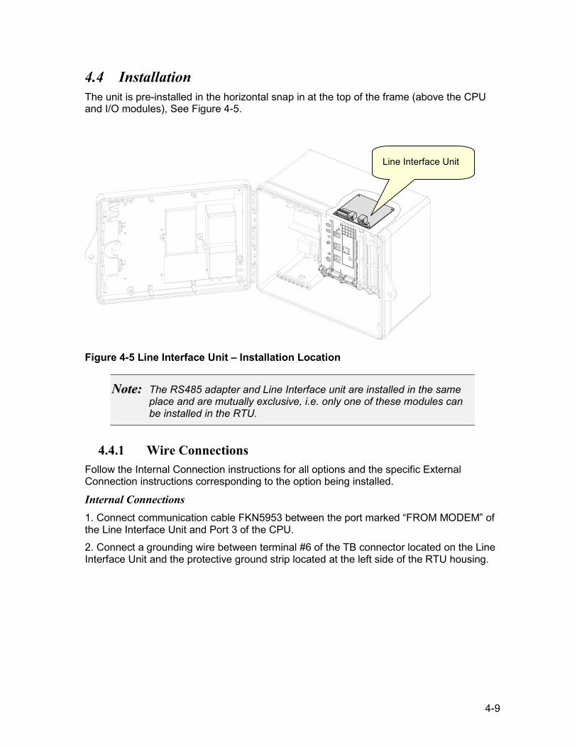
4-9
4.4 Installation The unit is pre-installed in the horizontal snap in at the top of the frame (above the CPU and I/O modules), See Figure 4-5.
Figure 4-5 Line Interface Unit – Installation Location
NNoottee:: The RS485 adapter and Line Interface unit are installed in the same place and are mutually exclusive, i.e. only one of these modules can be installed in the RTU.
4.4.1 Wire Connections Follow the Internal Connection instructions for all options and the specific External Connection instructions corresponding to the option being installed.
Internal Connections 1. Connect communication cable FKN5953 between the port marked “FROM MODEM” of the Line Interface Unit and Port 3 of the CPU. 2. Connect a grounding wire between terminal #6 of the TB connector located on the Line Interface Unit and the protective ground strip located at the left side of the RTU housing.
Line Interface Unit
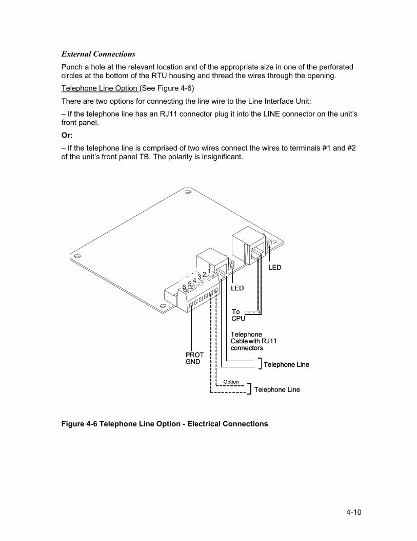
4-10
External Connections Punch a hole at the relevant location and of the appropriate size in one of the perforated circles at the bottom of the RTU housing and thread the wires through the opening. Telephone Line Option (See Figure 4-6)
There are two options for connecting the line wire to the Line Interface Unit: – If the telephone line has an RJ11 connector plug it into the LINE connector on the unit’s front panel. Or: – If the telephone line is comprised of two wires connect the wires to terminals #1 and #2 of the unit’s front panel TB. The polarity is insignificant.
Figure 4-6 Telephone Line Option - Electrical Connections
PROTGND
Telephone Cablewith RJ11 connectors
To CPU
LED
6 5 4 3 2 1
OptionTelephone Line
Telephone Line
LED
PROT GND
Telephone Cablewith RJ11 connectors
To CPU
LED
6 5 4 3 2 1
OptionTelephone Line
Telephone LineTelephone Line
LED
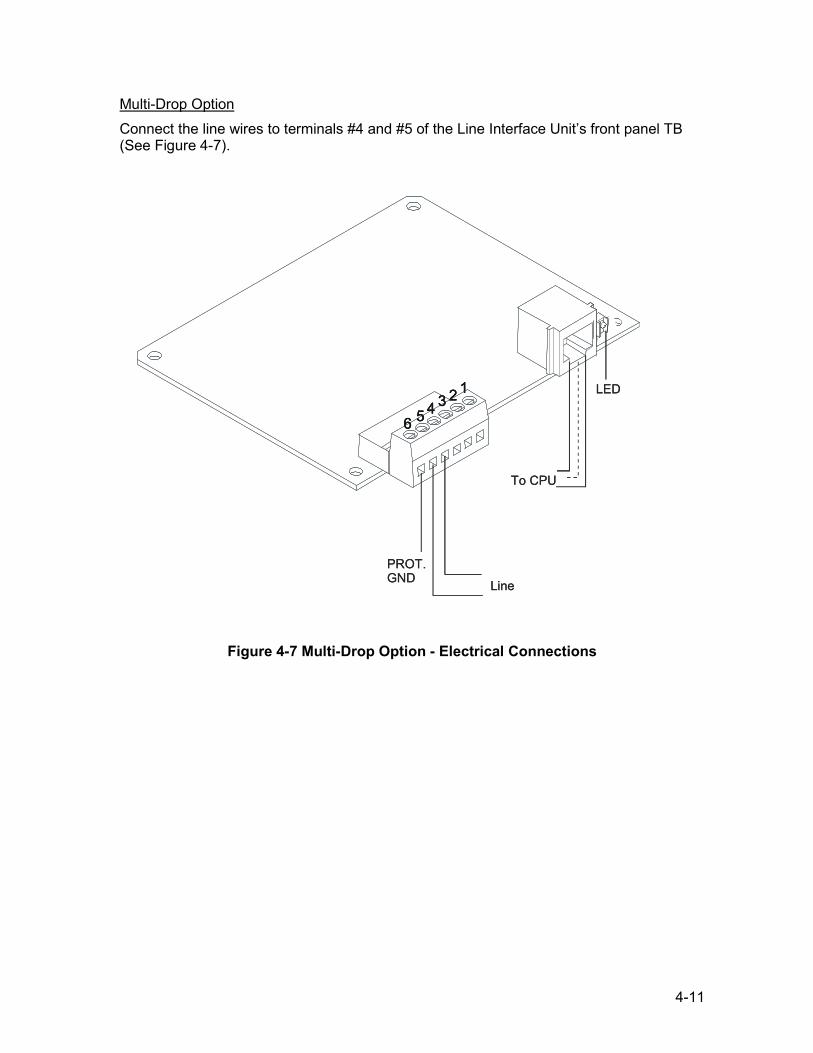
4-11
Multi-Drop Option Connect the line wires to terminals #4 and #5 of the Line Interface Unit’s front panel TB (See Figure 4-7).
Figure 4-7 Multi-Drop Option - Electrical Connections
6 5 4 3 2 1
PROT.GND Line
To CPU
LED
6 5 4 3 2 1
6 5 4 3 2 1
PROT.GND Line
To CPU
LED
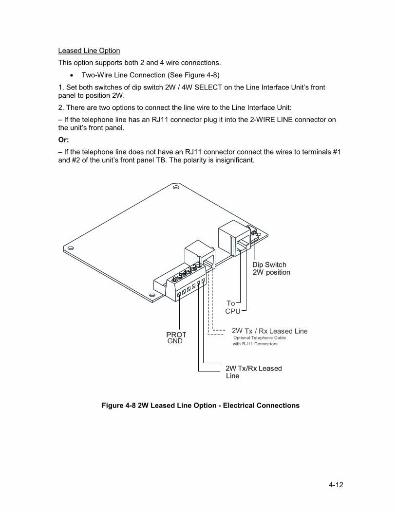
4-12
Leased Line Option This option supports both 2 and 4 wire connections.
• Two-Wire Line Connection (See Figure 4-8)
1. Set both switches of dip switch 2W / 4W SELECT on the Line Interface Unit’s front panel to position 2W. 2. There are two options to connect the line wire to the Line Interface Unit: – If the telephone line has an RJ11 connector plug it into the 2-WIRE LINE connector on the unit’s front panel. Or: – If the telephone line does not have an RJ11 connector connect the wires to terminals #1 and #2 of the unit’s front panel TB. The polarity is insignificant.
Figure 4-8 2W Leased Line Option - Electrical Connections
PROTGND
2W Tx/Rx LeasedLine
To
2W Tx / Rx Leased LineOptional Telephon e Cable with RJ11 Connectors
Dip Switch2W position
6 54321
PROT
2W Tx/Rx LeasedLine
CPU
Dip Switch2W position
6 54321
6 54321
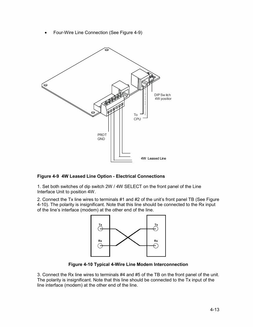
4-13
• Four-Wire Line Connection (See Figure 4-9)
Figure 4-9 4W Leased Line Option - Electrical Connections
1. Set both switches of dip switch 2W / 4W SELECT on the front panel of the Line Interface Unit to position 4W. 2. Connect the Tx line wires to terminals #1 and #2 of the unit’s front panel TB (See Figure 4-10). The polarity is insignificant. Note that this line should be connected to the Rx input of the line’s interface (modem) at the other end of the line.
Tx
Rx
Tx
Rx
Figure 4-10 Typical 4-Wire Line Modem Interconnection
3. Connect the Rx line wires to terminals #4 and #5 of the TB on the front panel of the unit. The polarity is insignificant. Note that this line should be connected to the Tx input of the line interface (modem) at the other end of the line.
6 54 3 2 1
PROTGND
4W Leased Line
To CPU
DIP Sw itch4W position
6 54 3 2 1
6 54 3 2 1
4W Leased Line
4-14
4.4.2 Removal and Installation
WWaarrnniinngg!! Before removing or installing a module, verify that the DC power is turned off.
Removing the Line Interface Unit To remove the Line Interface Unit from the RTU proceed as follows:
1. Turn off the DC power. 2. Disconnect the Line Interface Unit connections. 3. Remove the module by pressing the side snaps and lifting the module out.
Installing a Line Interface Unit
NNoottee:: If you are installing a new Line Interface Unit, remove it from the plastic cover and install the bare board in its place in the RTU housing.
To install a Line Interface Unit in the RTU proceed as follows: 1. Turn off the DC power 2. Place the module on the top of the multi-slot I/O card cage. Press down until
the snaps click into place. 3. Reconnect the Line Interface Unit connections.
4.4.3 Diagnostic LED’s The LED indications of the Line Interface Unit are described: Telephone Line Option
OFF HOOK – Indicates that the modem is in off-hook state (lit). RING – Indicates an incoming call ring (lit). Multi-Drop Option
TX – Indicates transmission from the modem (lit).
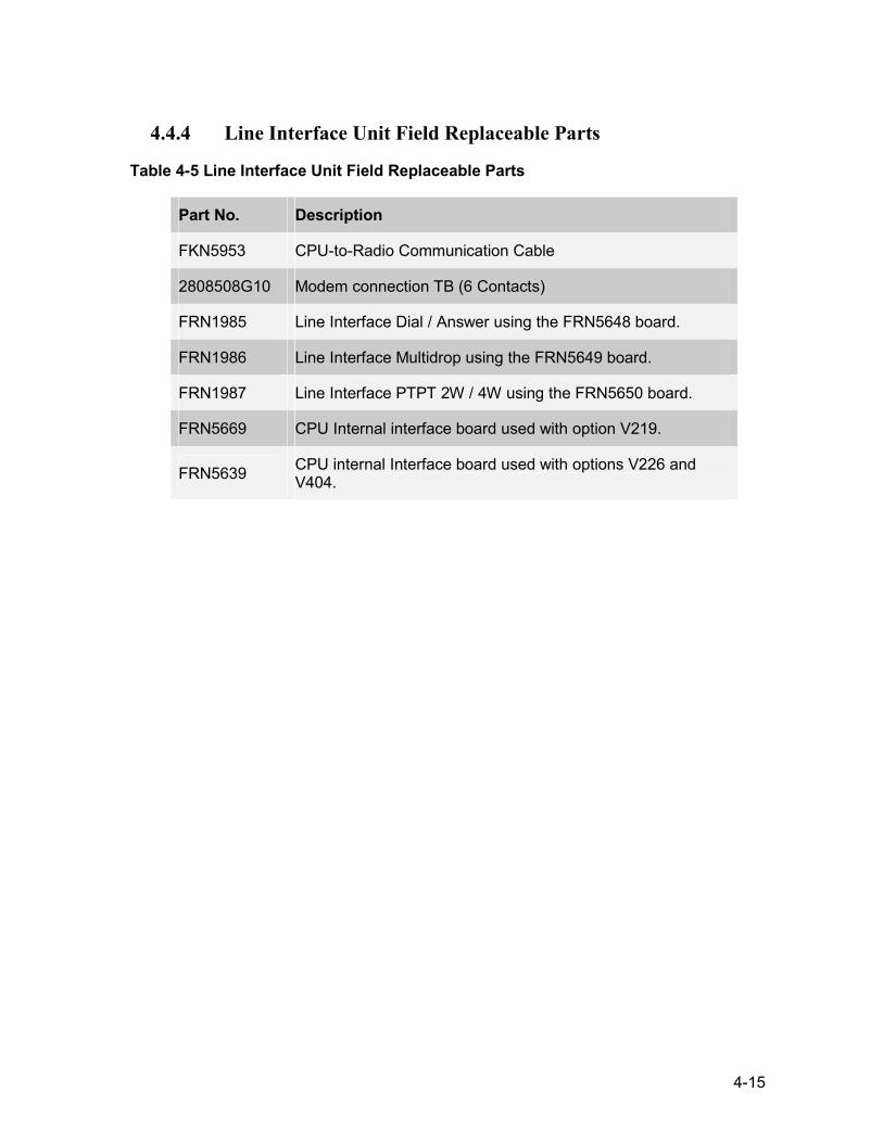
4-15
4.4.4 Line Interface Unit Field Replaceable Parts
Table 4-5 Line Interface Unit Field Replaceable Parts
Part No. Description
FKN5953 CPU-to-Radio Communication Cable
2808508G10 Modem connection TB (6 Contacts)
FRN1985 Line Interface Dial / Answer using the FRN5648 board.
FRN1986 Line Interface Multidrop using the FRN5649 board.
FRN1987 Line Interface PTPT 2W / 4W using the FRN5650 board.
FRN5669 CPU Internal interface board used with option V219.
FRN5639 CPU internal Interface board used with options V226 and V404.
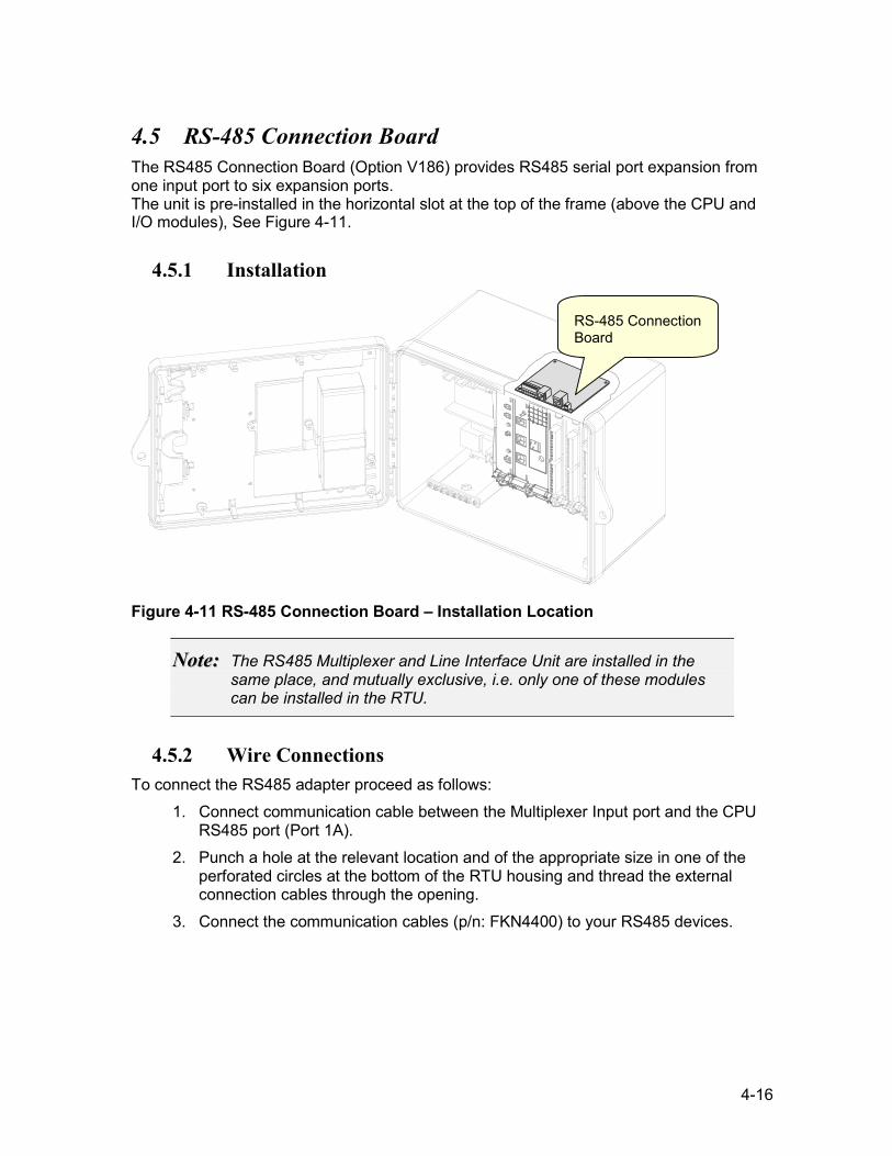
4-16
4.5 RS-485 Connection Board The RS485 Connection Board (Option V186) provides RS485 serial port expansion from one input port to six expansion ports. The unit is pre-installed in the horizontal slot at the top of the frame (above the CPU and I/O modules), See Figure 4-11.
4.5.1 Installation
Figure 4-11 RS-485 Connection Board – Installation Location
NNoottee:: The RS485 Multiplexer and Line Interface Unit are installed in the same place, and mutually exclusive, i.e. only one of these modules can be installed in the RTU.
4.5.2 Wire Connections To connect the RS485 adapter proceed as follows:
1. Connect communication cable between the Multiplexer Input port and the CPU RS485 port (Port 1A).
2. Punch a hole at the relevant location and of the appropriate size in one of the perforated circles at the bottom of the RTU housing and thread the external connection cables through the opening.
3. Connect the communication cables (p/n: FKN4400) to your RS485 devices.
RS-485 ConnectionBoard
4-17
4.5.3 Removal and Installation
WWaarrnniinngg!! Before removing or installing a module, verify that the DC power is turned off.
Removing the RS485 Connection Board To remove the RS485 Connection Board from the RTU proceed as follows:
1. Turn off the DC power. 2. Disconnect all RS485 Connection Board input and output connections. 3. Pull out the RS485 Multiplexer by pressing the side snaps.
Installing a RS485 Connection Board To install a RS485 Connection Board in the RTU proceed as follows:
1. Turn off the DC power. 2. Slide the RS485 Connection Board into its slot until the snaps click into place. 3. Reconnect the RS485 Adapter connection.
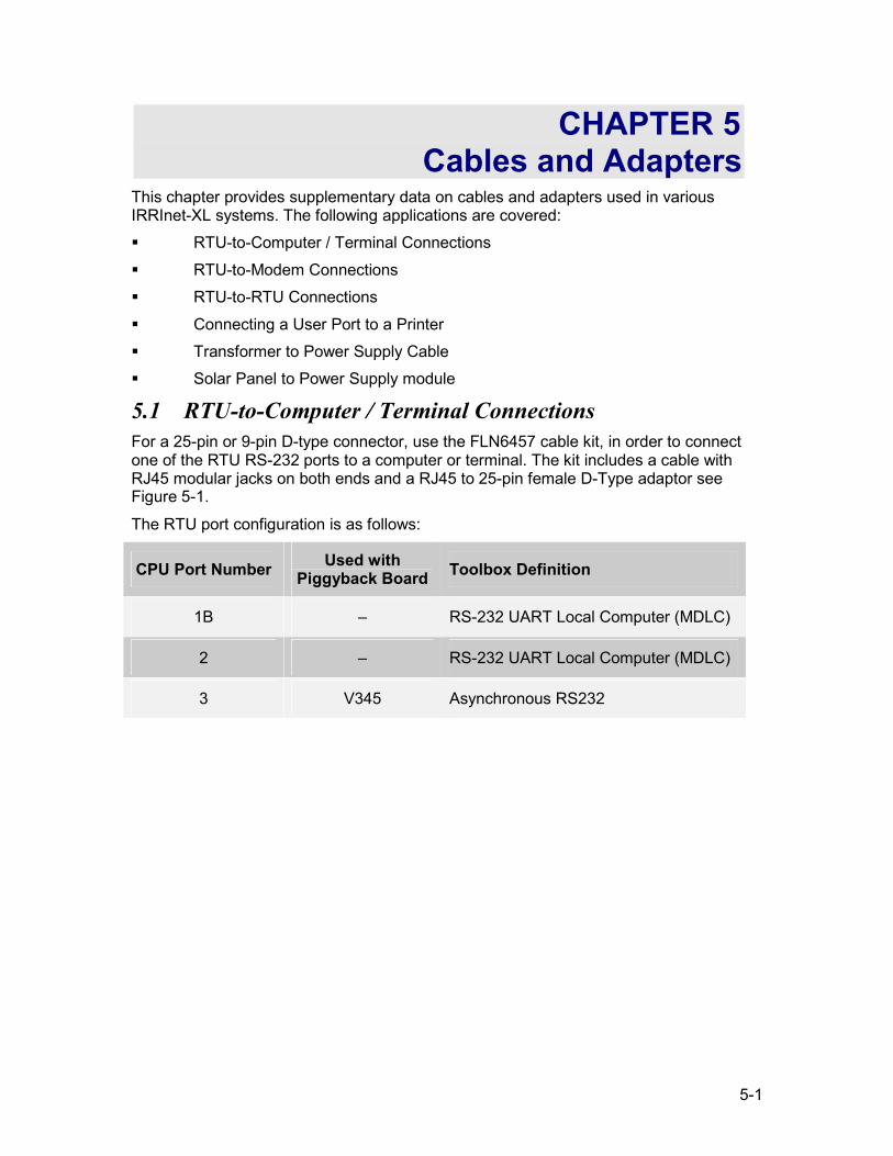
5-1
CHAPTER 5 Cables and Adapters
This chapter provides supplementary data on cables and adapters used in various IRRInet-XL systems. The following applications are covered: RTU-to-Computer / Terminal Connections RTU-to-Modem Connections RTU-to-RTU Connections Connecting a User Port to a Printer Transformer to Power Supply Cable Solar Panel to Power Supply module
5.1 RTU-to-Computer / Terminal Connections For a 25-pin or 9-pin D-type connector, use the FLN6457 cable kit, in order to connect one of the RTU RS-232 ports to a computer or terminal. The kit includes a cable with RJ45 modular jacks on both ends and a RJ45 to 25-pin female D-Type adaptor see Figure 5-1.
The RTU port configuration is as follows:
CPU Port Number Used with Piggyback Board Toolbox Definition
1B – RS-232 UART Local Computer (MDLC)
2 – RS-232 UART Local Computer (MDLC)
3 V345 Asynchronous RS232
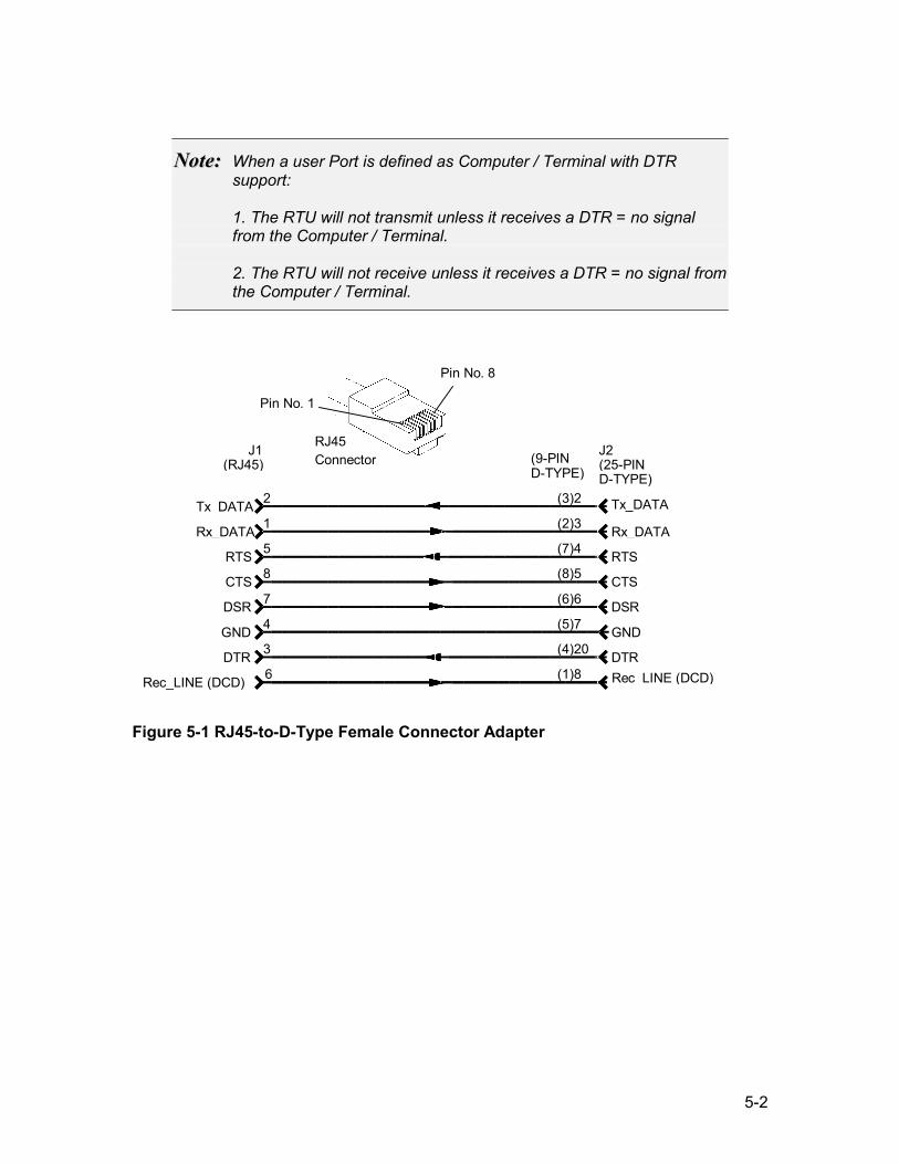
5-2
NNoottee:: When a user Port is defined as Computer / Terminal with DTR support: 1. The RTU will not transmit unless it receives a DTR = no signal from the Computer / Terminal. 2. The RTU will not receive unless it receives a DTR = no signal from the Computer / Terminal.
Figure 5-1 RJ45-to-D-Type Female Connector Adapter
J1 (RJ45)
J2(25-PIN D-TYPE)
Tx_DATA Rx_DATA
RTS CTS DSR GND DTR
Rec_LINE (DCD)
2
1
5
8
7
4
3
6
(3)2 (2)3 (7)4 (8)5 (6)6 (5)7 (4)20
(1)8
Tx_DATA
Rx_DATA RTS CTS DSR GND DTRRec_LINE (DCD)
(9-PIN D-TYPE)
RJ45 Connector
Pin No. 1
Pin No. 8
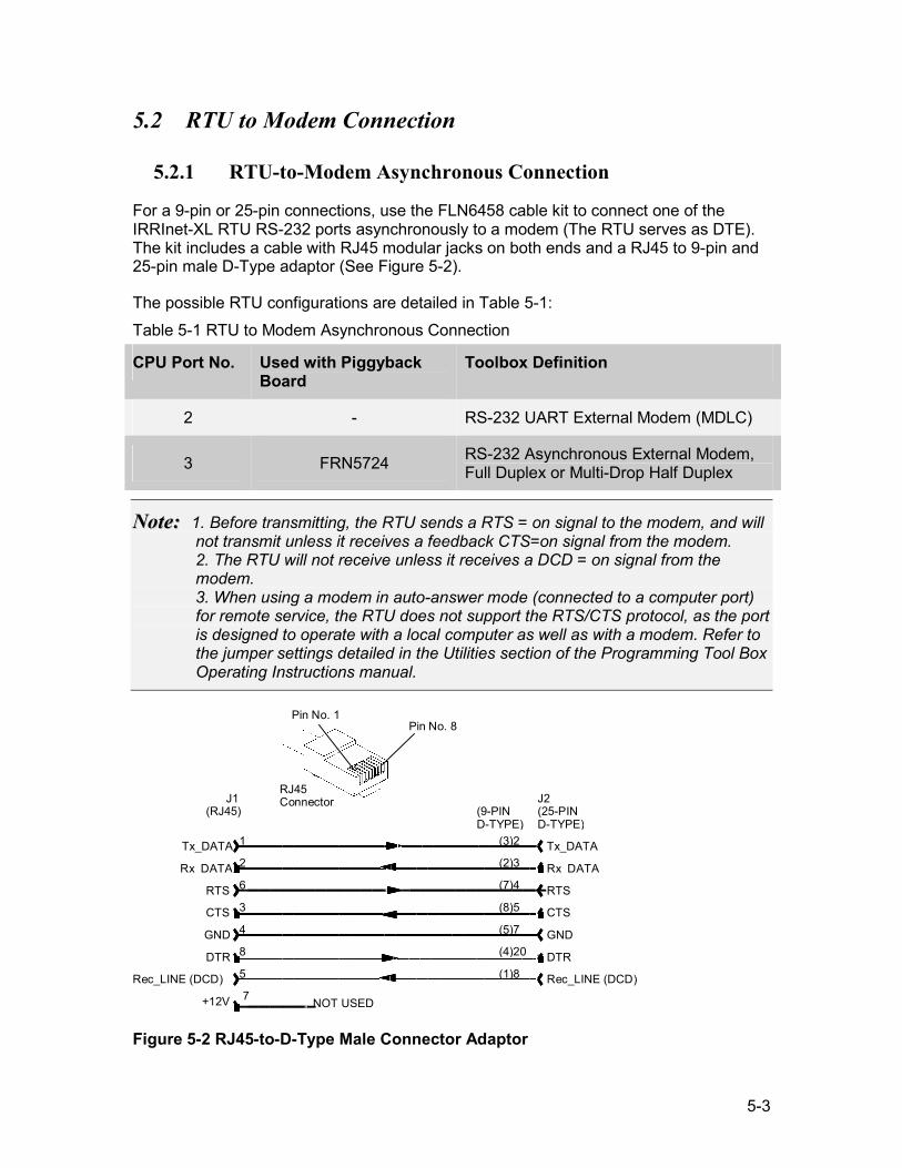
5-3
5.2 RTU to Modem Connection
5.2.1 RTU-to-Modem Asynchronous Connection
For a 9-pin or 25-pin connections, use the FLN6458 cable kit to connect one of the IRRInet-XL RTU RS-232 ports asynchronously to a modem (The RTU serves as DTE). The kit includes a cable with RJ45 modular jacks on both ends and a RJ45 to 9-pin and 25-pin male D-Type adaptor (See Figure 5-2).
The possible RTU configurations are detailed in Table 5-1: Table 5-1 RTU to Modem Asynchronous Connection
CPU Port No. Used with Piggyback Board
Toolbox Definition
2 - RS-232 UART External Modem (MDLC)
3 FRN5724 RS-232 Asynchronous External Modem, Full Duplex or Multi-Drop Half Duplex
NNoottee:: 1. Before transmitting, the RTU sends a RTS = on signal to the modem, and will not transmit unless it receives a feedback CTS=on signal from the modem. 2. The RTU will not receive unless it receives a DCD = on signal from the modem. 3. When using a modem in auto-answer mode (connected to a computer port) for remote service, the RTU does not support the RTS/CTS protocol, as the port is designed to operate with a local computer as well as with a modem. Refer to the jumper settings detailed in the Utilities section of the Programming Tool Box Operating Instructions manual.
J1 (RJ45)
J2 (25-PIN D-TYPE)
Tx_DATA Rx_DATA
RTS CTS GND DTR
Rec_LINE (DCD) +12V
1 2 6 3 4 8 5 7
(3)2 (2)3 (7)4 (8)5 (5)7 (4)20 (1)8
Tx_DATA Rx_DATA RTS
CTS
GND
DTR Rec_LINE (DCD)
NOT USED
(9-PIN D-TYPE)
RJ45 Connector
Pin No. 1 Pin No. 8
Figure 5-2 RJ45-to-D-Type Male Connector Adaptor
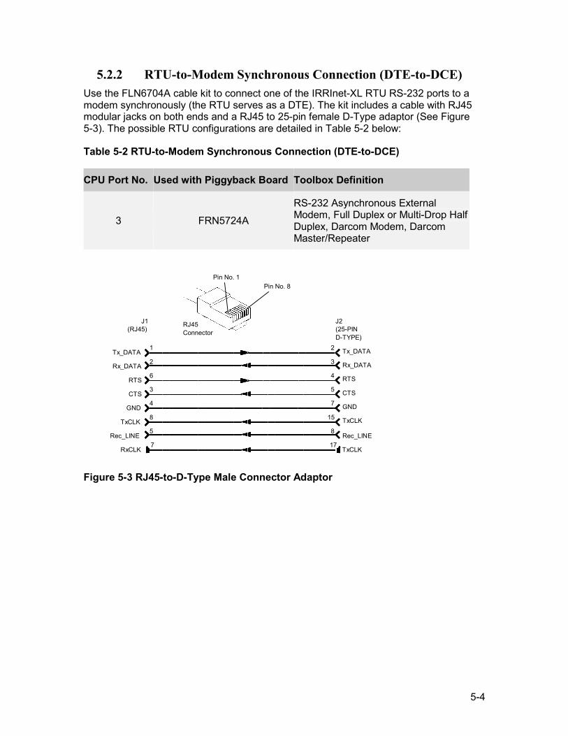
5-4
5.2.2 RTU-to-Modem Synchronous Connection (DTE-to-DCE) Use the FLN6704A cable kit to connect one of the IRRInet-XL RTU RS-232 ports to a modem synchronously (the RTU serves as a DTE). The kit includes a cable with RJ45 modular jacks on both ends and a RJ45 to 25-pin female D-Type adaptor (See Figure 5-3). The possible RTU configurations are detailed in Table 5-2 below:
Table 5-2 RTU-to-Modem Synchronous Connection (DTE-to-DCE)
CPU Port No. Used with Piggyback Board Toolbox Definition
3 FRN5724A
RS-232 Asynchronous External Modem, Full Duplex or Multi-Drop Half Duplex, Darcom Modem, Darcom Master/Repeater
J1 (RJ45)
J2 (25-PIN D-TYPE)
Tx_DATA Rx_DATA
RTS CTS
GND TxCLK
Rec_LINE RxCLK
1 2 6 3 4 8 5 7
2
3
4
5
7
15 8
Tx_DATA Rx_DATA RTS CTS GND
TxCLK Rec_LINE TxCLK
17
RJ45 Connector
Pin No. 1 Pin No. 8
Figure 5-3 RJ45-to-D-Type Male Connector Adaptor
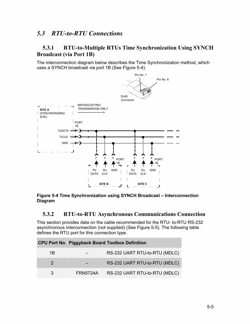
5-5
5.3 RTU-to-RTU Connections
5.3.1 RTU-to-Multiple RTUs Time Synchronization Using SYNCH Broadcast (via Port 1B) The interconnection diagram below describes the Time Synchronization method, which uses a SYNCH broadcast via port 1B (See Figure 5-4).
SITE A (SYNCHRONIZING SITE)
TxDATA TxCLK
GND
1
6
4
PORT 1B
BROADCASTING TRANSMISSION ONLY
2 3 4
Rx DATA
Rx CLK
GND
SITE B
2 3 4
Rx DATA
RxCLK
GND
SITE C
PORT 1B
PORT 1B
RJ45 Connector
Pin No. 1 Pin No. 8
Figure 5-4 Time Synchronization using SYNCH Broadcast – Interconnection Diagram
5.3.2 RTU-to-RTU Asynchronous Communications Connection This section provides data on the cable recommended for the RTU- to-RTU RS-232 asynchronous interconnection (not supplied) (See Figure 5-5). The following table defines the RTU port for this connection type.
CPU Port No. Piggyback Board Toolbox Definition
1B – RS-232 UART RTU-to-RTU (MDLC)
2 – RS-232 UART RTU-to-RTU (MDLC)
3 FRN5724A RS-232 UART RTU-to-RTU (MDLC)
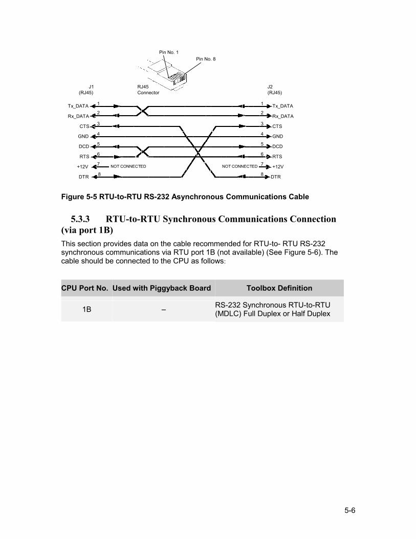
5-6
J1 (RJ45)
J2 (RJ45)
Tx_DATA Rx_DATA
CTS GND DCD RTS
+12V DTR
1 2 3 4 5 6 7 8
1 2 3 4 5 6 7
Tx_DATA Rx_DATA CTS GND DCD
RTS +12V
DTR8 NOT CONNECTED NOT CONNECTED
RJ45 Connector
Pin No. 1Pin No. 8
Figure 5-5 RTU-to-RTU RS-232 Asynchronous Communications Cable
5.3.3 RTU-to-RTU Synchronous Communications Connection (via port 1B) This section provides data on the cable recommended for RTU-to- RTU RS-232 synchronous communications via RTU port 1B (not available) (See Figure 5-6). The cable should be connected to the CPU as follows:
CPU Port No. Used with Piggyback Board Toolbox Definition
1B – RS-232 Synchronous RTU-to-RTU (MDLC) Full Duplex or Half Duplex
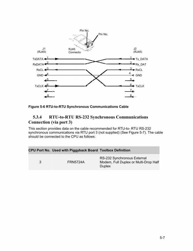
5-7
Tx_DATA
J1 (RJ45)
J2 (RJ45)
TxDATA RxDATA
RxCL
GND
TxCLK
1 2 3 4 5 6 7 8
1 2 3
4
5 6 7
Rx_DAT
RxCL
GND
TxCLK
8
RJ45 Connecto
Pin No. Pin No.
Figure 5-6 RTU-to-RTU Synchronous Communications Cable
5.3.4 RTU-to-RTU RS-232 Synchronous Communications Connection (via port 3) This section provides data on the cable recommended for RTU-to- RTU RS-232 synchronous communications via RTU port 3 (not supplied) (See Figure 5-7). The cable should be connected to the CPU as follows:
CPU Port No. Used with Piggyback Board Toolbox Definition
3 FRN5724A RS-232 Synchronous External Modem, Full Duplex or Multi-Drop Half Duplex
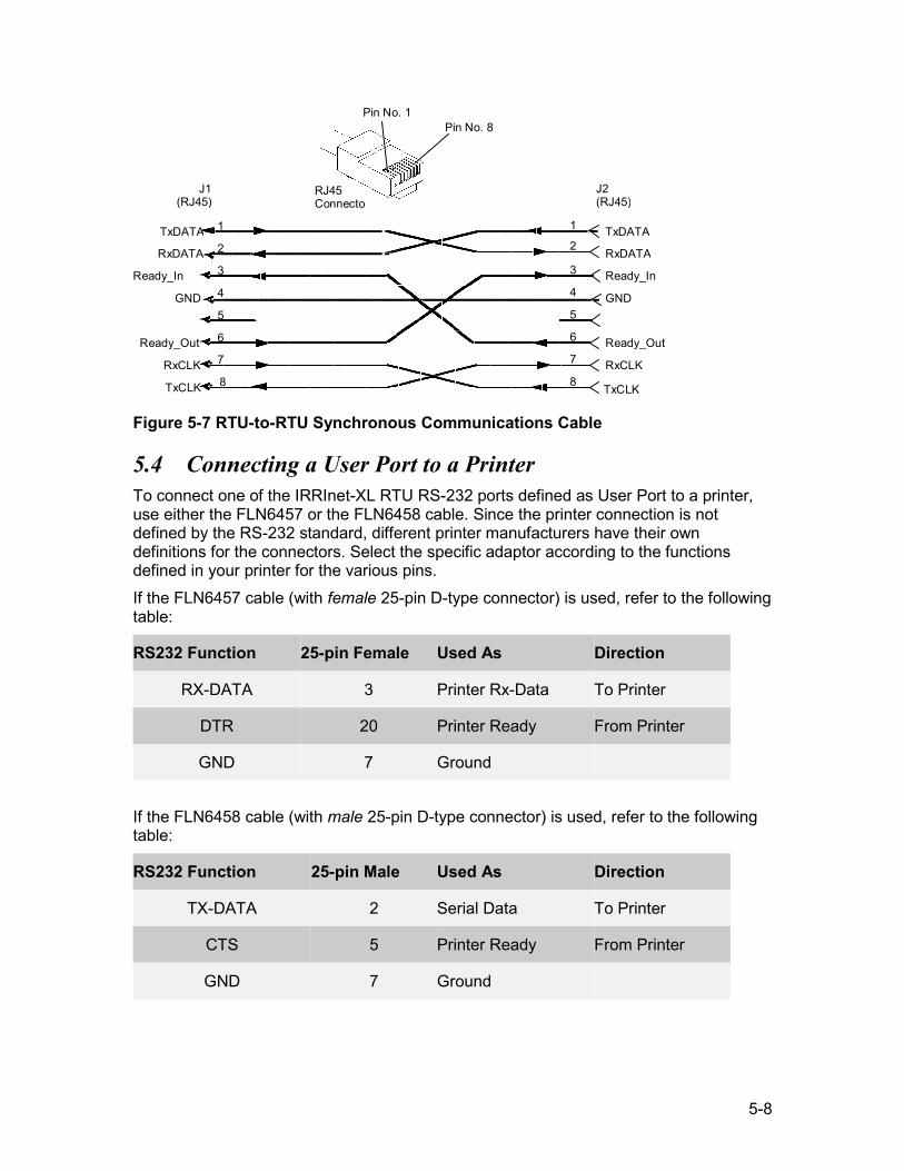
5-8
J1 (RJ45)
J2 (RJ45)
TxDATA RxDATA
Ready_In GND
Ready_Out RxCLK TxCLK
1 2 3 4 5 6 7 8
1 2 3 4 5 6 7
TxDATA
8
Ready_Out RxCLK TxCLK
RxDATA
GND
Ready_In
RJ45 Connecto
Pin No. 1Pin No. 8
Figure 5-7 RTU-to-RTU Synchronous Communications Cable
5.4 Connecting a User Port to a Printer To connect one of the IRRInet-XL RTU RS-232 ports defined as User Port to a printer, use either the FLN6457 or the FLN6458 cable. Since the printer connection is not defined by the RS-232 standard, different printer manufacturers have their own definitions for the connectors. Select the specific adaptor according to the functions defined in your printer for the various pins. If the FLN6457 cable (with female 25-pin D-type connector) is used, refer to the following table:
RS232 Function 25-pin Female Used As Direction
RX-DATA 3 Printer Rx-Data To Printer
DTR 20 Printer Ready From Printer
GND 7 Ground
If the FLN6458 cable (with male 25-pin D-type connector) is used, refer to the following table:
RS232 Function 25-pin Male Used As Direction
TX-DATA 2 Serial Data To Printer
CTS 5 Printer Ready From Printer
GND 7 Ground
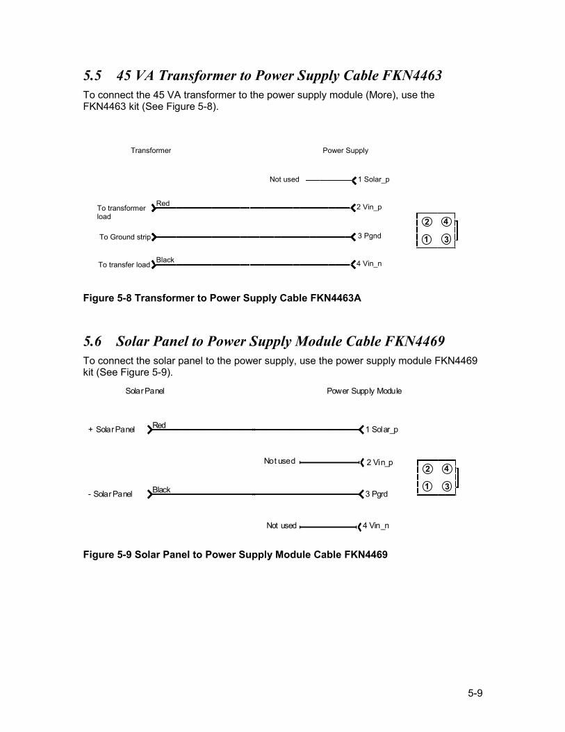
5-9
5.5 45 VA Transformer to Power Supply Cable FKN4463 To connect the 45 VA transformer to the power supply module (More), use the FKN4463 kit (See Figure 5-8).
Figure 5-8 Transformer to Power Supply Cable FKN4463A
5.6 Solar Panel to Power Supply Module Cable FKN4469 To connect the solar panel to the power supply, use the power supply module FKN4469 kit (See Figure 5-9).
Solar Panel Power Supply Module
+ Solar Panel Red
Black
1 Solar_p
2 Vin_p
3 Pgrd
Not used
4 Vin_nNot used
- Solar Panel
Figure 5-9 Solar Panel to Power Supply Module Cable FKN4469
Transformer Power Supply
To transformer load
To Ground strip
To transfer load
Red
Black
2 Vin_p
3 Pgnd
4 Vin_n
1 Solar_pNot used
2 4
1 3
2 4
1 3
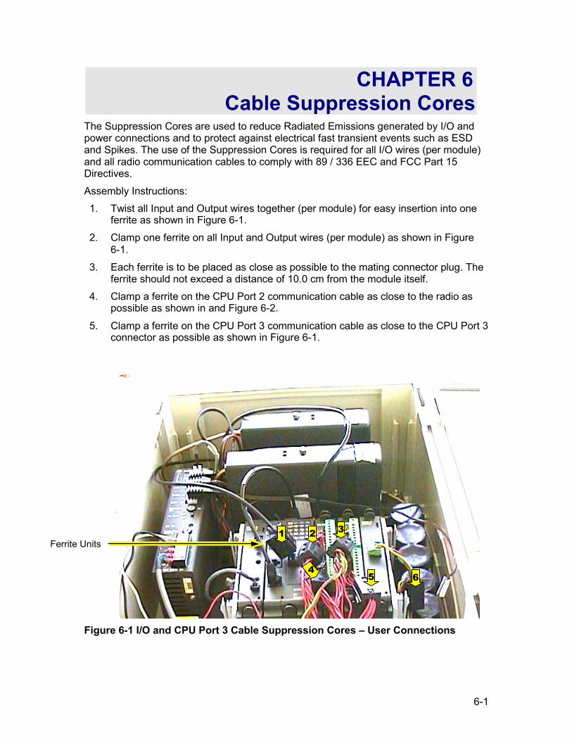
6-1
CHAPTER 6 Cable Suppression Cores
The Suppression Cores are used to reduce Radiated Emissions generated by I/O and power connections and to protect against electrical fast transient events such as ESD and Spikes. The use of the Suppression Cores is required for all I/O wires (per module) and all radio communication cables to comply with 89 / 336 EEC and FCC Part 15 Directives. Assembly Instructions: 1. Twist all Input and Output wires together (per module) for easy insertion into one
ferrite as shown in Figure 6-1. 2. Clamp one ferrite on all Input and Output wires (per module) as shown in Figure
6-1. 3. Each ferrite is to be placed as close as possible to the mating connector plug. The
ferrite should not exceed a distance of 10.0 cm from the module itself. 4. Clamp a ferrite on the CPU Port 2 communication cable as close to the radio as
possible as shown in and Figure 6-2.
5. Clamp a ferrite on the CPU Port 3 communication cable as close to the CPU Port 3 connector as possible as shown in Figure 6-1.
Figure 6-1 I/O and CPU Port 3 Cable Suppression Cores – User Connections
Ferrite Units 1 2 3
5 6 4
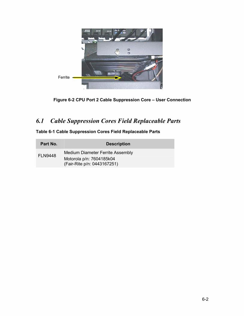
6-2
Figure 6-2 CPU Port 2 Cable Suppression Core – User Connection
6.1 Cable Suppression Cores Field Replaceable Parts Table 6-1 Cable Suppression Cores Field Replaceable Parts
Part No. Description
FLN9448
Medium Diameter Ferrite Assembly Motorola p/n: 7604185k04 (Fair-Rite p/n: 0443167251)
Ferrite
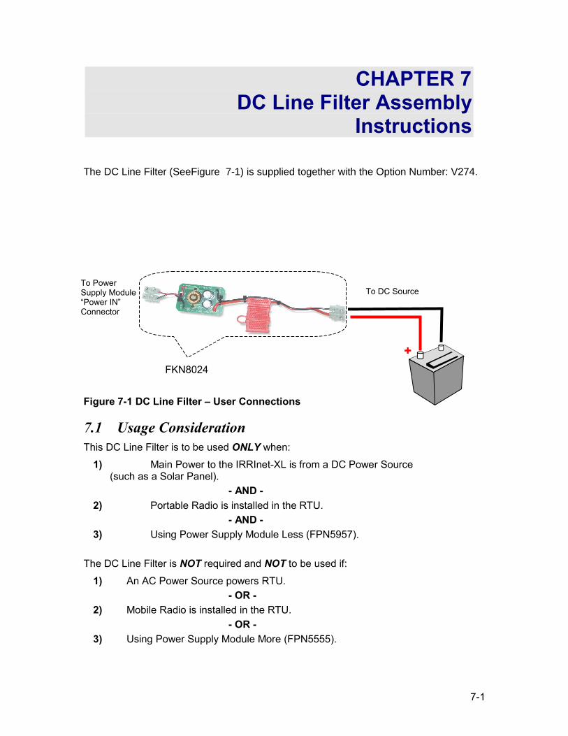
7-1
CHAPTER 7 DC Line Filter Assembly
Instructions
The DC Line Filter (SeeFigure 7-1) is supplied together with the Option Number: V274.
Figure 7-1 DC Line Filter – User Connections
7.1 Usage Consideration This DC Line Filter is to be used ONLY when:
1) Main Power to the IRRInet-XL is from a DC Power Source (such as a Solar Panel).
- AND - 2) Portable Radio is installed in the RTU.
- AND - 3) Using Power Supply Module Less (FPN5957).
The DC Line Filter is NOT required and NOT to be used if:
1) An AC Power Source powers RTU. - OR -
2) Mobile Radio is installed in the RTU. - OR -
3) Using Power Supply Module More (FPN5555).
To DC Source
+
To Power Supply Module “Power IN” Connector
FKN8024
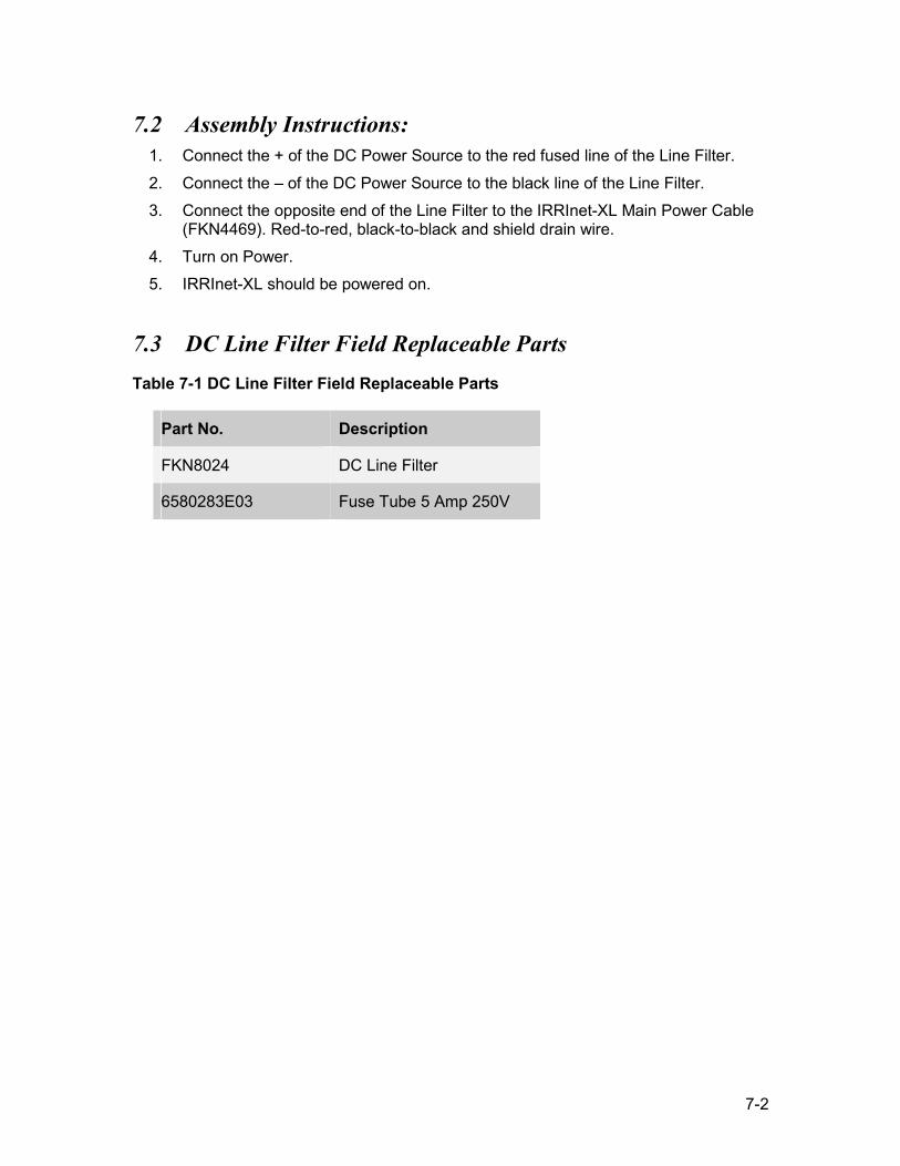
7-2
7.2 Assembly Instructions: 1. Connect the + of the DC Power Source to the red fused line of the Line Filter. 2. Connect the – of the DC Power Source to the black line of the Line Filter. 3. Connect the opposite end of the Line Filter to the IRRInet-XL Main Power Cable
(FKN4469). Red-to-red, black-to-black and shield drain wire. 4. Turn on Power. 5. IRRInet-XL should be powered on.
7.3 DC Line Filter Field Replaceable Parts Table 7-1 DC Line Filter Field Replaceable Parts
Part No. Description
FKN8024 DC Line Filter
6580283E03 Fuse Tube 5 Amp 250V
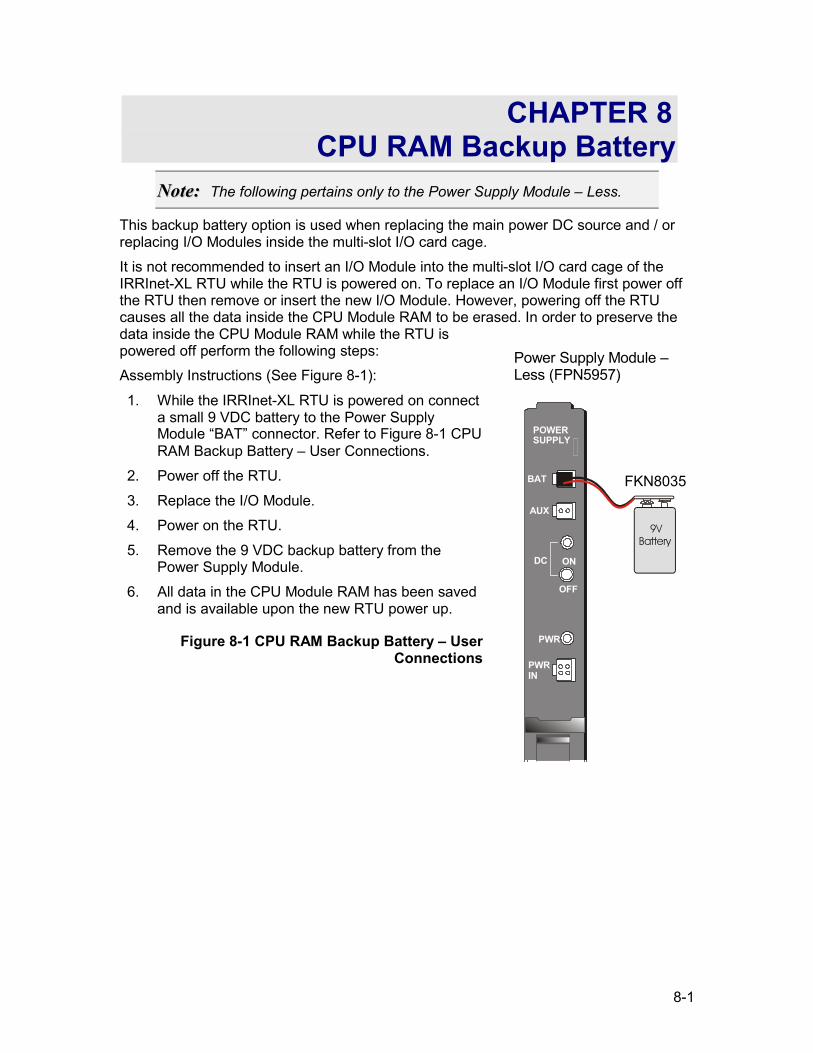
8-1
CHAPTER 8 CPU RAM Backup Battery
NNoottee:: The following pertains only to the Power Supply Module – Less.
This backup battery option is used when replacing the main power DC source and / or replacing I/O Modules inside the multi-slot I/O card cage. It is not recommended to insert an I/O Module into the multi-slot I/O card cage of the IRRInet-XL RTU while the RTU is powered on. To replace an I/O Module first power off the RTU then remove or insert the new I/O Module. However, powering off the RTU causes all the data inside the CPU Module RAM to be erased. In order to preserve the data inside the CPU Module RAM while the RTU is powered off perform the following steps: Assembly Instructions (See Figure 8-1):
1. While the IRRInet-XL RTU is powered on connect a small 9 VDC battery to the Power Supply Module “BAT” connector. Refer to Figure 8-1 CPU RAM Backup Battery – User Connections.
2. Power off the RTU. 3. Replace the I/O Module. 4. Power on the RTU. 5. Remove the 9 VDC backup battery from the
Power Supply Module. 6. All data in the CPU Module RAM has been saved
and is available upon the new RTU power up.
Figure 8-1 CPU RAM Backup Battery – User Connections
POWERSUPPLY
BAT
AUX
DC ON
OFF
PWR
PWRIN
9V Battery
Power Supply Module – Less (FPN5957)
FKN8035