Embed Size (px)
Citation preview

Engng Applic. Artif. lntell. Vol. 6, No. 5, pp. 425-435, 1993 0952-1976/93 $6.00+0.00 Printed in Great Britain. All rights reserved Copyright © 1993 Pergamon Press Ltd
Contributed Paper
A Knowledge-based System for Centrifugal Fan Blade Design Y. CHON
University of Illinois at Chicago
K. I. KIM University of Illinois at Chicago
K. KIM University of Illinois at Chicago
(Received in revised form April 1993)
The objective of this study is to design the optimal centrifugal fan with specific given conditions, by using a knowledge-based system. In this study, the significant factors for the centrifugal fan such as input variables, output variables and constraints are conceptualized. These conceptualized factors are translated into mathematical forms by centrifugal fan theory. A knowledge data base is developed using the expertise of fan design experts, and a corresponding rule set is developed and applied using an inference engine. A simulation study demonstrates the effectiveness of the proposed steategy.
Keywords: Centrifugal fan, knowledge-based system, certainty factor, efficiency, capacity, noise, head, flow rate.
1. INTRODUCTION
A knowledge-based system approach can be applied to tasks that require symbol manipulation or heuristic solutions, or tasks that rely on practical experience rather than mathematical representation. 1-3 In centrifu- gal fan blade design, the effect of each factor on the design is so complicated that it cannot be easily realized in a mathematical form. Though the design has been expressed in a mathematical form, the results deviate greatly from the experimental results. For these rea- sons, the designer should combine the centrifugal fan theory and the experiences of human experts. Therefore, the objective of this study is to design the optimal centrifugal fan with specific given conditions by using a knowledge-based system. The proposed approach can be combined with the knowledge-based system to decide the detailed information about the designer's input variables and design conditions.
The above objective will be achieved by the follow- ing steps:
(1) Create the significant factors such as input vari- ables, output variables, and constraints.
Correspondence should be sent to: K. Kim, Department of Mechanical Engineering, University of Illinois at Chicago, Chicago, IL 60680, U.S.A.
(2) Derive the significant factors for a backward- type centrifugal fan to mathematical represen- tations.
(3) Create the knowledge data base with the help of the fan experts.
(4) Develop an individual rule set according to the logic of the knowledge-based system.
(5) Combine each individual rule set with the others by using an inference engine.
(6) Implement a subset of the knowledge-based system, using C language.
(7) Analyse the results through simulation.
2. SIGNIFICANT FACTORS FOR DESIGNING CENTRIFUGAL FAN BLADES
To design a centrifugal fan, there are three major factors: the input data, the constraints, and the output data. Generally in a real case, the available limits of motor speed and outlet diameter have already been decided, and the designer has to design the fan within these limits. Therefore, the criteria of the motor speed and outlet diameter are considered first, and the output will be generated within these limits. There are several constraints in designing a centrifugal fan: head, speed coefficient, volume coefficient. The input data will be
425
426 Y. CHON et al.: CENTRIFUGAL FAN BLADE DESIGN
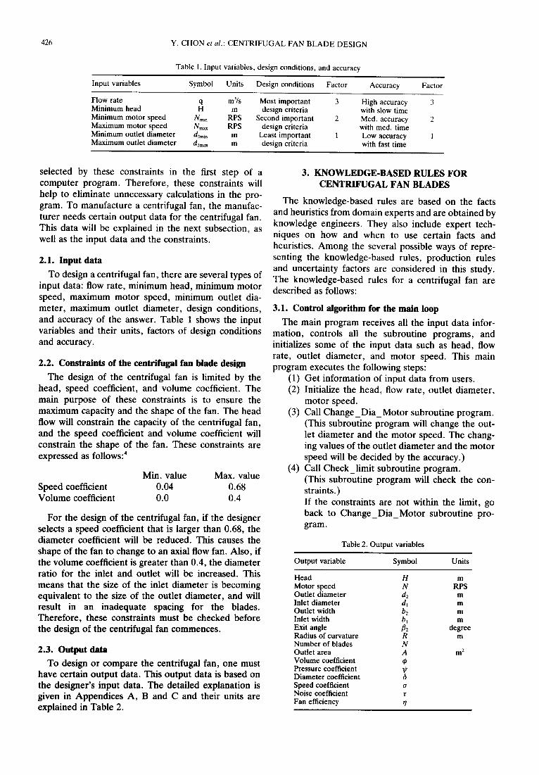
Table 1. Input variables, design conditions, and accuracy
Input variables Symbol Uni ts Design conditions F a c t o r Accuracy Factor
Flow rate q m3/s Most important 3 High accuracy 3 Minimum head H m design criteria with slow time Minimum motor speed N mi n RPS Second important 2 Med. accuracy 2 Maximum motor speed Nmax RPS design criteria with med. time Minimum outlet diameter d2m~, m Least important 1 Low accuracy 1 Maximum outlet diameter d2max m design criteria with fast time
selected by these constraints in the first step of a computer program. Therefore, these constraints will help to eliminate unnecessary calculations in the pro- gram. To manufacture a centrifugal fan, the manufac- turer needs certain output data for the centrifugal fan. This data will be explained in the next subsection, as well as the input data and the constraints.
2.1. Input data
To design a centrifugal fan, there are several types of input data: flow rate, minimum head, minimum motor speed, maximum motor speed, minimum outlet dia- meter, maximum outlet diameter, design conditions, and accuracy of the answer. Table 1 shows the input variables and their units, factors of design conditions and accuracy.
2.2. Constraints of the centrifugal fan blade design
The design of the centrifugal fan is limited by the head, speed coefficient, and volume coefficient. The main purpose of these constraints is to ensure the maximum capacity and the shape of the fan. The head flow will constrain the capacity of the centrifugal fan, and the speed coefficient and volume coefficient will constrain the shape of the fan. These constraints are expressed as follows: 4
Min. value Max. value Speed coefficient 0.04 0.68 Volume coefficient 0.0 0.4
For the design of the centrifugal fan, if the designer selects a speed coefficient that is larger than 0.68, the diameter coefficient will be reduced. This causes the shape of the fan to change to an axial flow fan. Also, if the volume coefficient is greater than 0.4, the diameter ratio for the inlet and outlet will be increased. This means that the size of the inlet diameter is becoming equivalent to the size of the outlet diameter, and will result in an inadequate spacing for the blades. Therefore, these constraints must be checked before the design of the centrifugal fan commences.
2.3. Output data
To design or compare the centrifugal fan, one must have certain output data. This output data is based on the designer's input data. The detailed explanation is given in Appendices A, B and C and their units are explained in Table 2.
3. KNOWLEDGE-BASED RULES FOR CENTRIFUGAL FAN BLADES
The knowledge-based rules are based on the facts and heuristics from domain experts and are obtained by knowledge engineers. They also include expert tech- niques on how and when to use certain facts and heuristics. Among the several possible ways of repre- senting the knowledge-based rules, production rules and uncertainty factors are considered in this study. The knowledge-based rules for a centrifugal fan are described as follows:
3.1. Control algorithm for the main loop
The main program receives all the input data infor- mation, controls all the subroutine programs, and initializes some of the input data such as head, flow rate, outlet diameter, and motor speed. This main program executes the following steps:
(1) Get information of input data from users. (2) Initialize the head, flow rate, outlet diameter,
motor speed. (3) Call Change_Dia_Motor subroutine program.
(This subroutine program will change the out- let diameter and the motor speed. The chang- ing values of the outlet diameter and the motor speed will be decided by the accuracy.)
(4) Call Check_limit subroutine program. (This subroutine program will check the con- straints.) If the constraints are not within the limit, go back to Change_Dia_Motor subroutine pro- gram.
Table 2. Output variables
Output variable Symbol Units
Head H Motor speed N Outlet diameter d2 Inlet diameter d~ Outlet width b2 Inlet width b~ Exit angle fiE Radius of curvature R Number of blades N Outlet area A Volume coefficient Pressure coefficient Diameter coefficient Speed coefficient a Noise coefficient r Fan efficiency r/
m
RPS m m
m m
degree m
m 2

Y. CHON et al.: CENTRIFUGAL FAN BLADE DESIGN 427
Otherwise, go to next step. (5) Check whether the outlet diameter and motor
speed are greater than their maximum values. If they are greater than their maximum values, exit the main program and ask for new input data. Otherwise, go to next step.
(6) Calculate the inlet angle and inlet diameter. (7) Check whether the inlet diameter is greater
than the outlet diameter multiplied by 0.8. If it is true, go to step 10 Otherwise, go to next step.
(8) Call Expert_Rules_Based subroutine pro- gram. (This subroutine program will change the head and flow rate, call the fan subroutine program, and print the output data. The fan program will calculate the output data based on the designer's input variables, and store the output data for every changing value of the input variables. Among the output data, the main program will select the optimum output data for each speci- fic given condition.)
(9) Check whether maximum efficiency, noise, and capacity are equal to zero. If it is true, go to next step. Otherwise, print the output data and exit the program.
(10) Change the outlet diameter and motor speed again. Execute steps 5 to 9 again.
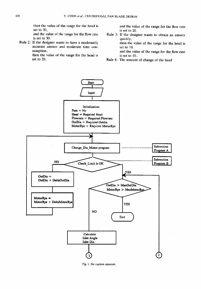
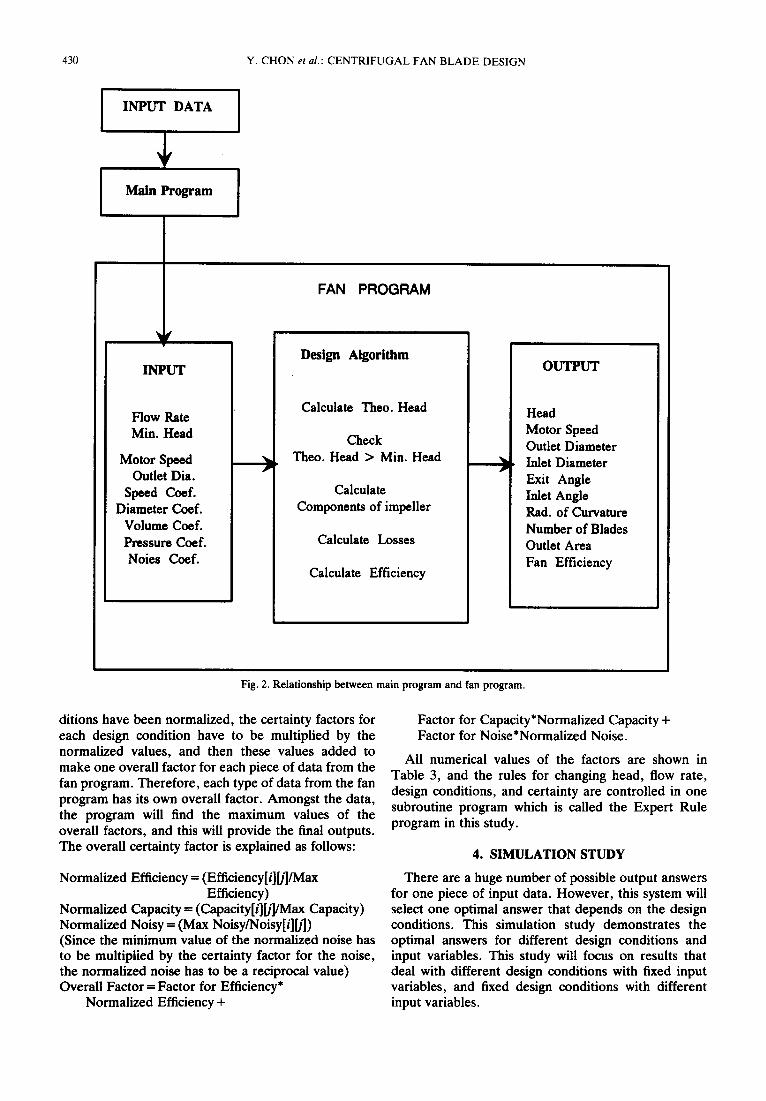
The flow chart for main program is shown in Fig. 1, and the relationship between fan and main program in Fig. 2.
3.2. Knowledge based rules
A. Changing outlet diameter and motor speed
The main purpose of the centrifugal fan design is to maintain the minimum outlet diameter and the mini- mum motor speed within the design conditions and the required head. However, in certain situations, it is impossible to maintain the minimum outlet diameter and the minimum motor speed within the design con- ditions, while at the same time satisfying the required head. Therefore, either the outlet diameter and motor speed, or the head and flow rate must be changed to satisfy the design conditions and the required head. Since the outlet diameter and motor speed have greater priority than the head and flow rate, the head and flow rate will be changed first. The rules for changing the outlet diameter and motor speed are as follows:
Rule 1: If the designer wants to have a highly accurate answer, then the value of the range for the outlet diameter is set to 60, and the value of the range for the motor speed is set to 12.
Rule 2:
Rule 3:
Rule 4:
Rule 5:
If the designer wants to have medium accur- acy in the answer, with medium time con- sumption, then the value of the range for the outlet diameter is set to 40, and the value of the range for the motor speed is set to 8.0. If the designer wants to obtain an answer quickly, then the value of the range for the outlet diameter is set to 20, and the value of the range for the motor speed is set to 4.0. The amount of change of the outlet diame- ter = (Maximum outlet diameter - Required outlet diameter)/ the number of range for outlet diameter The amount of change of the motor speed =(Maximum motor speed - Required motor speed)/ the number of range for motor speed.
B. Checking constraints
To avoid unnecessary calculations, the program must check whether the constraints are within limits before further calculations are undertaken. To do this, the algorithm must contain certain rules in its calculation of the coefficients which are changed by the head and flow rate. After this step, the calculated values for the coefficients will be checked. If the calculated values are within their limits, the program will process the next step. Otherwise, the program will stop and request new input data. This rule can be explained as follows:
Diameter coefficient= 1.865*Outlet Diameter*(Head/ FlowRate2) °.25
Speed Coefficient = 0.379*Motor RPS*(FlowRate:/ Head3) °-25
Flow Coefficient = 1/(Speed Coefficient*Diameter Coefficient 3) IF (Speed Coefficient>Minimum Speed Coefficient and Speed Coefficient<Maximum Speed Coefficient and Flow Coefficient<Maximum Flow Coefficient) Then Goto the next step Else Stop and request the new input.
C. Changing head and flow rate
Due to the main constraints on the fan design the head and flow rate have to be changed before the outlet diameter and motor speed. In a case where the design condition and the required head are not satisfied, even though the head and flow rate have been changed up to their maximum value, then the outlet diameter and motor speed have to be changed.
The rules for changing the head and flow rate are as follows:
Rule 1: If the designer wants to have a highly accurate answer,
428 Y. CHON et al.: CENTRIFUGAL FAN BLADE DESIGN
then the value of the range for the head is set to 30, and the value of the range for the flow rate is set to 30.
Rule 2: If the designer wants to have a moderately accurate answer and modera te time con- sumption, then the value of the range for the head is set to 20,
Rule 3:
Rule 4:
and the value of the range for the flow rate is set to 20. If the designer wants to obtain an answer quickly, then the value of the range for the head is set to 10. and the value of the range for the flow rate is set to 10. The amount of change of the head
( ) I
I
Initialization Pass = No Head = Required Head Flowrate = Required Flowrate OutDia = Required Outdia MotorRps = Required MotorRps
"1 Change_Dia_Motor program
I ~ i i ...................... Subroutine
OutDia = OutDia + DeltaOutDia
I MotorRps = [ MotorRps + DeltaMotorRps
I
................................ [Subroutine[Program A
YES
Calculate [ Inlet Angle Inlet Dia
Fig. 1. See caption opposite.
©
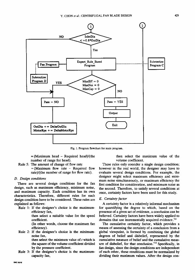
Y. CHON et al.: CENTRIFUGAL FAN BLADE DESIGN 429
r'l Fa,, Program
Subroutine I Program D
YES
,J G
Pass = NO
OutDia + = DeltaOutDia MotorRps + = DeltaMotorRps
NO
Expert_RuleBased Program t .............................
M a x ~ o i - 0
I I Pass = YES
I I °utput I I
)
t
®
Subroutine Program C
Fig. 1. Program flowchart for main program.
= (Maximum head - Required head)/(the number of range for head).
Rule 5: The amount of change of flow rate =(Maximum flow rate - Required flow rate)/(the number of range for flow rate).
D. Design conditions
There are several design conditions for the fan design, such as maximum efficiency, minimum noise, and maximum capacity. Each condition has its own characteristics. Therefore, different rules for each design condition have to be considered. These rules are explained as follows:
Rule 1: If the designer's choice is the maximum- efficiency fan, then select a suitable value for the speed coefficient. (In other words, choose the maximum fan efficiency).
Rule 2: If the designer's choice is the minimum- noise fan, then select the minimum value of t which is the square of the volume coefficient divided by the pressure coefficient.
Rule 3: If the designer's choice is the maximum- capacity fan,
then select the maximum value of the volume coefficient.
These rules only consider a single design condition; however in the real world, the designer may have to evaluate several design conditions. For example, the designer might select maximum efficiency and mini- mum noise simultaneously, or maximum efficiency the first condition for consideration, and minimum noise as the second. Therefore, to satisfy several conditions at once, certainty factors have been used for this study.
E. Certainty factor
A certainty factor is a relatively informal mechanism for quantifying the degree to which, based on the presence of a given set of evidence, a conclusion can be believed. Certainty factors have been widely applied to domains that use incrementally acquired evidence. 5'6
The cumulative certainty factor, which provides a means of assessing the certainty of a conclusion from a global viewpoint, is formed by combining the global degrees of belief and disbelief, represented by the cumulative measure of belief and the cumulative meas- ure of disbelief, for that conclusion. 7-9 Specifically, in fan design, since the design conditions are independent of each other, these conditions must be normalized by dividing their maximum values. After the design con-
fOAl l l l - I
430 Y. CHON et al.: CENTRIFUGAL FAN BLADE DESIGN
INPUT DATA
Main Program
FAN PROGRAM
f
INPUT
Flow Pate Min. Head
Motor Speed Outlet Dia.
Speed Coef. Diameter Coef.
Volume Coef. Pressure Coef. Noies Coef.
Design Algorithm
Calculate Theo. Head
Check Theo. Head > Min. Head
Calculate Components of impeller
Calculate Losses
Calculate Efficiency
.__.)
OUTPUT
Head Motor Speed Outlet Diameter Inlet Diameter Exit Angle Inlet Angle Pad. of Curvature Number of Blades Outlet Area Fan Efficiency
Fig. 2. Relationship between main program and fan program.
ditions have been normalized, the certainty factors for each design condition have to be multiplied by the normalized values, and then these values added to make one overall factor for each piece of data from the fan program. Therefore, each type of data from the fan program has its own overall factor. Amongst the data, the program will find the maximum values of the overall factors, and this will provide the final outputs. The overall certainty factor is explained as follows:
Factor for Capacity*Normalized Capacity + Factor for Noise*Normalized Noise.
All numerical values of the factors are shown in Table 3, and the rules for changing head, flow rate, design conditions, and certainty are controlled in one subroutine program which is called the Expert Rule program in this study.
4. SIMULATION STUDY
Normalized Efficiency = (Efficiency[i][/]/Max Efficiency)
Normalized Capacity = (Capacity[/][/]/Max Capacity) Normalized Noisy = (Max Noisy/Noisy[i][/]) (Since the minimum value of the normalized noise has to be multiplied by the certainty factor for the noise, the normalized noise has to be a reciprocal value) Overall Factor = Factor for Efficiency*
Normalized Efficiency +
There are a huge number of possible output answers for one piece of input data. However, this system will select one optimal answer that depends on the design conditions. This simulation study demonstrates the optimal answers for different design conditions and input variables. This study will focus on results that deal with different design conditions with fixed input variables, and fixed design conditions with different input variables.
Y. CHON et al.: CENTRIFUGAL FAN BLADE DESIGN 431
Table 3. Certainty factor for efficiency, noise, and capacity
Capacity 3 2 1
Efficiency = 3 Noise
3
1
Efficiency = 2 Noise
3
1
Efficiency = 1
Noise 3
FE 0.4 FE 0.4 FE 0.5 FN 0.1 FN 0.1 FN 0.5 FC 0.4 FC 0.2 FC 0.0 FE 0.5 FE 0.6 FE 0.8 FN 0.1 FN 0.1 FN 0.2 FC 0.5 FC 0.5 FC 0.0 FE 0.5 FE 0.7 FE 1.0 FN 0.0 FN 0.0 FN 0.0 FC 0.5 FC 0.3 FC 0.0
FE 0.2 FE 0.3 FE FN 0.4 FN 0.4 FN FC 0.4 FC 0.3 FC FE 0.3 FE 0.4 FE FN 0.1 FN 0.1 FN FC 0.4 FC 0.4 FC FE 0.3 FE 0.4 FE FN 0.0 FN 0.0 FN FC 0.7 FC 0.4 FC
FE 0.0 FE 0.0 FE FN 0.5 FN 0.7 FN FC 0.5 FC 0.3 FC FE 0.0 FE 0.0 FE FN 0.1 FN 0.0 FN FC 0.8 FC 0.4 FC FE 0.0 FE 0.0 FE FN 0.0 FN 0.0 FN FC 1.0 FC 0.8 FC
FE: Efficiency Factor. FN: Noise Factor. Design Conditions: Most considerable design criteria--3. Second considerable design criteria--2. Least considerable design criteria--1.
FC: Capacity Factor.
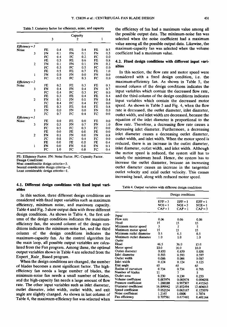
the efficiency of fan had a maximum value among all the possible output data. The minimum-noise fan was selected when the noise coefficient had a maximum value among all the possible output data. Likewise, the maximum-capacity fan was selected when the volume coefficient had a maximum value.
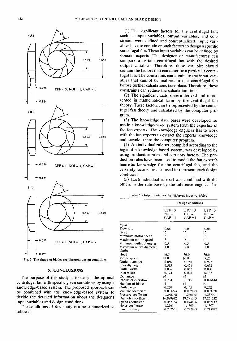
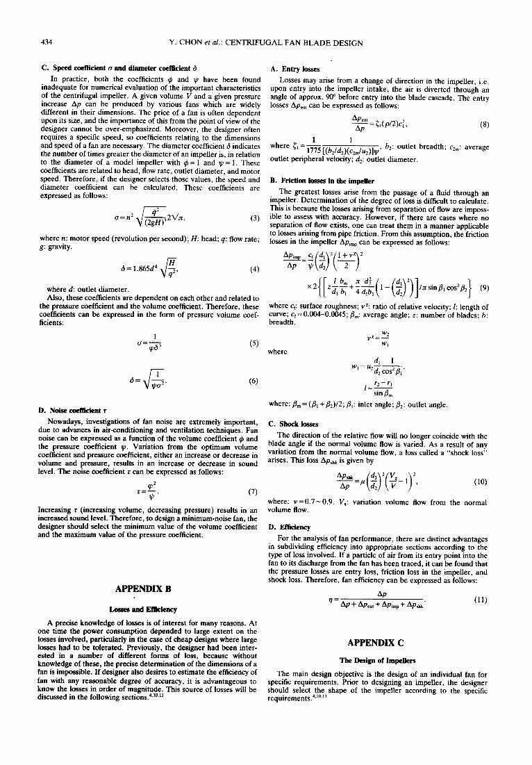
4.2. Fixed design conditions with different input vari- ables
In this section, the flow rate and motor speed were considered with a fixed design condition, i.e. the maximum-efficiency fan. As shown in Table 5, the
o.3 second column of the design conditions indicates the 0.7 0.0 input variables which contain the decreased flow rate, 0.4 and the third column of the design conditions indicates o.4 input variables which contain the decreased motor 0.0 0.8 speed. As shown in Table 5 and Fig. 4, when the flow 0.0 rate is decreased, the outlet diameter, inlet diameter, 0.0 outlet width, and inlet width are decreased, because the 0.0 equation of the inlet diameter is proportional to the 1.0 flow rate. Therefore, a decreasing flow rate causes a 0.0 decreasing inlet diameter. Furthermore, a decreasing 0.0 0.8 inlet diameter causes a decreasing outlet diameter, 0.0 outlet width, and inlet width. When the motor speed is o.4 reduced, there is an increase in the outlet diameter, 0.1 0.4 inlet diameter, outlet width, and inlet width. Although
the motor speed is reduced, the system still has to satisfy the minimum head. Hence, the system has to increase the outlet diameter, because an increasing outlet diameter causes an increase in the tangential outlet velocity and axial outlet velocity. This causes increasing head, along with reduced motor speed.
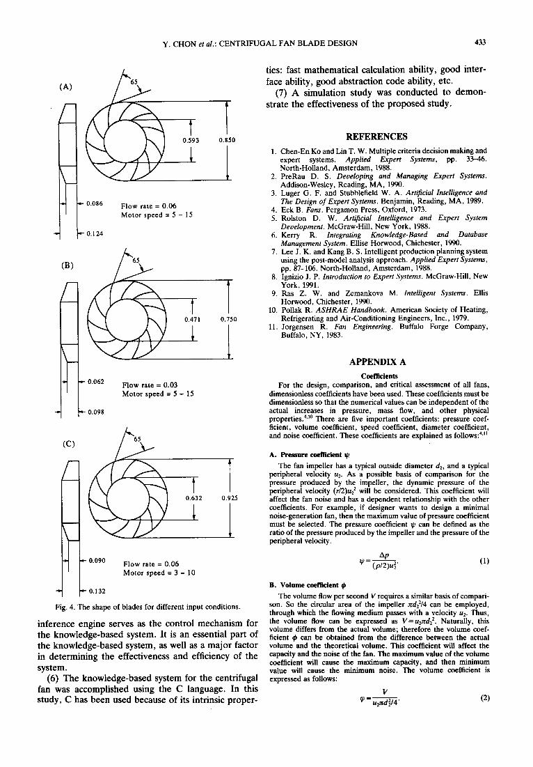
4.1. Different design conditions with fixed input vari- ables
In this section, three different design conditions are considered with fixed input variables such as maximum efficiency, minimum noise, and maximum capacity. Table 4 and Fig. 3 show output data with three different design conditions. As shown in Table 4, the first col- umn of the design conditions indicates the maximum- efficiency fan, the second column of the design con- ditions indicates the minimum-noise fan, and the third column of the design conditions indicates the maximum-capacity fan. As the control algorithm for the main loop, all possible output variables are calcu- lated from the Fan program. Among these, the optimal output variables shown in Table 4 are selected from the Expert_Rule_Based program.
When the design conditions are changed, the number of blades becomes a most significant factor. The high- efficiency fan needs a large number of blades, the minimum-noise fan needs a small number of blades, and the high-capacity fan needs a large amount of flow rate. The other input variables such as inlet diameter, outlet diameter, inlet width, outlet width, and exit angle are slightly changed. As shown in last column of Table 4, the maximum-efficiency fan was selected when
Table 4. Output variables with different design conditions
Design conditions
EFF = 3 EFF = 1 EFF-- 1 NOI = 1 NOI = 3 NOI = 1 CAP = 1 CAP = 1 CAP = 3
I n p u t
Flow rate 0.06 0.06 0.06 Head 15 15 15 Minimum motor speed 5 5 5 Maximum motor speed 15 15 15 Minimum outlet diameter 0.5 0.5 0.5 Maximum outlet diameter 1.0 1.0 1.0 Outlet Head 46.5 36.0 15.0 Motor speed I0.0 10.0 10.0 Outlet diameter 0.850 0.850 0.850 Inlet diameter 0.593 0.593 0.597 Outlet width 0.086 0.086 0.087 Inlet width 0.124 0.124 0.125 Exit angle 65 65 65 Radius of curvature 0.734 0.734 0.705 Number of blades 11 7 5 Outlet area 0.230 0.230 0.233 Volume coefficient 0.003974 0.003974 0.004058 Pressure coefficient 1.288188 0.997307 0.415545 Diameter coefficient 16.899942 15.852494 12.604013 Speed coefficient 0.052134 0.063167 0.123079 Noise coefficient 1.2165 1.0800 1.7874 Fan efficiency 0.707561 0.677492 0.481164
432 Y. CHON et al.: C E N T R I F U G A L FAN B L A D E DESIGN
°°6 0.124 FF 3NoI CAP
(B)
0.593
~ 0.086 EFF = 1, NOI = 3, CAP = 1
.i- 0.124
0.850
0.850
(C) 65
0.597 0.850
* t -- 0.087 EFF -- 1, NOI = 1, CAP -- 3
"- 0.125
Fig. 3. The shape of blades for different design conditions.
5. CONCLUSIONS
The purpose of this study is to design the optimal centrifugal fan with specific given conditions by using a knowledge-based system. The proposed approach can be combined with the knowledge-based system to decide the detailed information about the designer's input variables and design conditions.
The conditions of this study can be summarized as follows:
(1) The significant factors for the centrifugal fan, such as input variables, output variables, and con- straints were defined and conceptualized. Input vari- ables have to contain enough factors to design a specific centrifugal fan. These input variables can be defined by domain experts. The designer or manufacturer can compare a certain centrifugal fan with the desired output variables. Therefore, these variables should contain the factors that can describe a particular centri- fugal fan. The constraints can eliminate the input vari- ables that cannot be realized in that centrifugal fan before further calculations take place. Therefore, these constraints can reduce the calculation time.
(2) The significant factors were derived and repre- sented in mathematical form by the centrifugal fan theory. These factors can be represented by the centri- fugal fan theory and calculated by the computer pro- gram.
(3) The knowledge data bases were developed for use in a knowledge-based system from the expertise of the fan experts. The knowledge engineer has to work with the fan experts to extract the experts' knowledge and encode it into the computer program.
(4) An individual rule set, compiled according to the logic of a knowledge-based system, was developed by using production rules and certainty factors. The pro- duction rules have been used to model the fan expert's heuristic knowledge for the centrifugal fan, and the certainty factors are also used to represent each design condition.
(5) Each individual rule set was combined with the others in the rule base by the inference engine. This
Table 5. Output variables for different input variables
Design conditions
EFF = 3 EFF = 3 EFF = 3 N O I = 1 NOI = 1 N O I = 1 CAP = 1 CAP = 1 CAP = 1
lnpul Flow rate 0.06 11.113 0.06 Head 15 15 15 Minimum motor speed 5 5 3 Maximum motor speed 15 15 1(1 Minimum outlet diameter 0.5 0.5 0.5 Maximum outlet diameter 1.0 1.1) 1.0 Outlet Head 46.5 36.0 36.0 Motor speed 10.0 10.0 8.25 Outlet diameter I).850 0.750 0.925 Inlet diameter 0.593 0.471 0.632 Outlet width 0.086 0.062 0.090 Inlet width 0.124 0.098 I). 132 Exit angle 65 65 65 Radius of curvature 0.734 1.245 0.898644 Number of blades 11 11 10 Outlet area 0.230 0.145 0.262 Volume coefficient 0.003974 0 .1~12893 0.003738 Pressure coefficient 1.288188 1.280985 1.237301 Diameter coefficient 16.899942 19.7813115 17.251242 Speed coefficient 0.052134 0.044666 11.052113 Noise coefficient 1.2165 1.1305 1.1507 Fan efficiency 0.707561 0.742985 tl.717942
Y. CHON et al.: CENTRIFUGAL FAN BLADE DESIGN 433
0.593
(B)
/- m l
0.471
"t -~ 0.062 Flow rate = 0.03 Motor speed = 5 - 15
~- 0.098
0.850
0.750
(c)
1 ' 0.632 0.925
Eo.o9o Motor speed = 3 - 10
0.132
Fig. 4. The shape of blades for different input conditions.
inference engine serves as the control mechanism for the knowledge-based system. It is an essential part of the knowledge-based system, as well as a major factor in determining the effectiveness and efficiency of the system.
(6) The knowledge-based system for the centrifugal fan was accomplished using the C language. In this study, C has been used because of its intrinsic proper-
ties: fast mathematical calculation ability, good inter- face ability, good abstraction code ability, etc.
(7) A simulation study was conducted to demon- strate the effectiveness of the proposed study.
REFERENCES
1. Chen-En Ko and Lin T. W. Multiple criteria decision making and expert systems. Applied Expert Systems, pp. 33-46. North-Holland, Amsterdam, 1988.
2. PreRau D. S. Developing and Managing Expert Systems. Addison-Wesley, Reading, MA, 1990.
3. Luger G. F. and Stubblefield W. A. Artificial Intelligence and The Design of Expert Systems. Benjamin, Reading, MA, 1989.
4. Eck B. Fans. Pergamon Press, Oxford, 1973. 5. Rolston D. W. Artificial Intelligence and Expert System
Development. McGraw-Hill, New York, 1988. 6. Kerry R. Integrating Knowledge-Based and Database
Management System. Ellise Horwood, Chichester, 1990. 7. Lee J. K. and Kang B. S. Intelligent production planning system
using the post-model analysis approach. Applied Expert Systems, pp. 87-106. North-Holland, Amsterdam, 1988.
8. Ignizio J. P. Introduction to Expert Systems. McGraw-Hill, New York, 1991.
9. Ras Z. W. and Zemankova M. Intelligent Systems. Ellis Horwood, Chichester, 1990.
10. Pollak R. ASHRAE Handbook. American Society of Heating, Refrigerating and Air-Conditioning Engineers, Inc., 1979.
11. Jorgensen R. Fan Engineering. Buffalo Forge Company, Buffalo, NY, 1983.
APPENDIX A Coefficients
For the design, comparison, and critical assessment of all fans, dimensionless coefficients have been used. These coefficients must be dimensionless so that the numerical values can be independent of the actual increases in pressure, mass flow, and other physical properties. 4,1° There are five important coefficients: pressure coef- ficient, volume coefficient, speed coefficient, diameter coefficient, and noise coefficient. These coefficients are explained as follows: 4'n
A. Pressure coefficient
The fan impeller has a typical outside diameter d2, and a typical peripheral velocity u2. As a possible basis of comparison for the pressure produced by the impeller, the dynamic pressure of the peripheral velocity (r/2)u22 will be considered. This coefficient will affect the fan noise and has a dependent relationship with the other coefficients. For example, if designer wants to design a minimal noise-generation fan, then the maximum value of pressure coefficient must be selected. The pressure coefficient ~o can be defined as the ratio of the pressure produced by the impeller and the pressure of the peripheral velocity.
Ap - (p/2)u22. (1)
B. Volume coefficient
The volume flow per second V requires a similar basis of compari- son. So the circular area of the impeller ~d22/4 can be employed, through which the flowing medium passes with a velocity u2. Thus, the volume flow can be expressed as V= UeTtd22. Naturally, this volume differs from the actual volume; therefore the volume coef- ficient ~ can be obtained from the difference between the actual volume and the theoretical volume. This coefficient will affect the capacity and the noise of the fan. The maximum value of the volume coefficient will cause the maximum capacity, and then minimum value will cause the minimum noise. The volume coefficient is expressed as follows:
V cp = u~d214. (2)
434 Y. CHON et al.: CENTRIFUGAL FAN BLADE DESIGN
C. Speed coefficient o and diameter coefficient b
In practice, both the coefficients q~ and ~/, have been found inadequate for numerical evaluation of the important characteristics of the centrifugal impeller. A given volume V and a given pressure increase Ap can be produced by various fans which are widely different in their dimensions. The price of a fan is often dependent upon its size, and the importance of this from the point of view of the designer cannot be over-emphasized. Moreover, the designer often requires a specific speed, so coefficients relating to the dimensions and speed of a fan are necessary. The diameter coefficient 6 indicates the number of times greater the diameter of an impeller is, in relation to the diameter of a model impeller with tp = 1 and ~p = 1. These coefficients are related to head, flow rate, outlet diameter, and motor speed. Therefore, if the designer selects those values, the speed and diameter coefficient can be calculated. These coefficients are expressed as follows:
O = n 2 ~ 2 X / x , (3)
where n: motor speed (revolution per second); H: head; q: flow rate; g: gravity.
= 1.865d 4 ~ 2 , (4)
where d: outlet diameter. Also, these coefficients are dependent on each other and related to
the pressure coefficient and the volume coefficient. Therefore, these coefficients can be expressed in the form of pressure volume coef- ficients:
1 o= ~ 3 (5)
= . (6)
D. Noise coefficient r
Nowadays, investigations of fan noise are extremely important, due to advances in air-conditioning and ventilation techniques. Fan noise can be expressed as a function of the volume coefficient ~ and the pressure coefficient 1/,. Variation from the optimum volume coefficient and pressure coefficient, either an increase or decrease in volume and pressure, results in an increase or decrease in sound level. The noise coefficient r can be expressed as follows:
q02 r = - - . (7)
Increasing r (increasing volume, decreasing pressure) results in an increased sound level. Therefore, to design a minimum-noise fan, the designer should select the minimum value of the volume coefficient and the maximum value of the pressure coefficient.
APPENDIX B
Losses and Elqklency
A precise knowledge of losses is of interest for many reasons. At one time the power consumption depended to large extent on the losses involved, particularly in the case of cheap designs where large losses had to be tolerated. Previously, the designer had been inter- ested in a number of different forms of loss, because without knowledge of these, the precise determination of the dimensions of a fan is impossible. If designer also desires to estimate the efficiency of fan with any reasonable degree of accuracy, it is advantageous to know the losses in order of magnitude. This source of losses will be discussed in the following sections. 4a°'n
A. Entry losses
Losses may arise from a change of direction in the impeller, i.e. upon entry into the impeller intake, the air is diverted through an angle of approx. 90 ° before entry into the blade cascade. The entry losses Ap~,t can be expressed as follows:
Apenl Ap = ~i(p/2)c~, (8)
1 I where ~i 1775 [(b2/d2)(C2m/U2)]V,' b2: outlct breadth; c2m: average outlet peripheral velocity; d2: outlct diameter.
B. Friction losses in the impeller
The greatest losses arise from the passage of a fluid through an impeller. Determination of the degree of loss is difficult to calculate. This is because the losses arising from separation of flow are imposs- ible to assess with accuracy. However, if there are cases where no separation of flow exists, one can treat them in a manner applicable to losses arising from pipe friction. From this assumption, the friction losses in the impeller Apimp can be expressed as follows:
A p i m . c f / d l \ 2 / l + v X ~ 2
_ ' [ Ibm :r d~ [ -fdl~2~]l:rsinfllc°s2fl2)] t (9)
where q: surface roughness; vZ: ratio of relative velocity; 1: length of curve; c~= 0.004-0.0045; tim: average angle; z: number of blades; b: breadth.
V X : W2
WI where
d I 1 W 1 = U2d2 COS2 f l l "
r 2 - - r l
1 = sin tim
where: tim = (ill +fl2)/2; ill: inlet angle; f12: outlet angle.
C. Shock losses
The direction of the relative flow will no longer coincide with the blade angle if the normal volume flow is varied. As a result of any variation from the normal volume flow, a loss called a "shock loss" arises. This loss Apshk is given by
Ap,h k /d,~2/Vz .~2 ="lz) l v - ' J , (10)
where: v=0 .7~0 .9 . Vx: variation volume flow from the normal volume flow.
D. Efficiency
For the analysis of fan performance, there are distinct advantages in subdividing efficiency into appropriate sections according to the type of loss involved. If a particle of air from its entry point into the fan to its discharge from the fan has been traced, it can be found that the pressure losses are entry loss, friction loss in the impeller, and shock loss. Therefore, fan efficiency can be expressed as follows:
Ap ~/ Ap + Ape,t + Apimp + Apshk" (11)
APPENDIX C
The Design of Impellers
The main design objective is the design of an individual fan for specific requirements. Prior to designing an impeller, the designer should select the shape of the impeller according to the specific requirements. 4.10al
Y. CHON et al.: CENTRIFUGAL FAN BLADE DESIGN 435
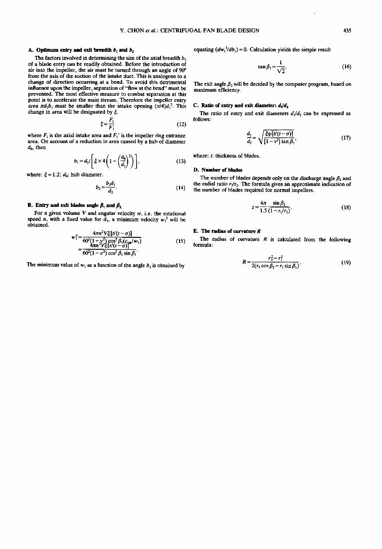
A. Optimum entry and exit breadth bl and b2
The factors involved in determining the size of the axial breadth bn of a blade entry can be readily obtained. Before the introduction of air into the impeller, the air must be turned through an angle of 90 ° from the axis of the suction of the intake duct. This is analogous to a change of direction occurring at a bend. To avoid this detrimental influence upon the impeller, separation of "flow at the bend" must be prevented. The most effective measure to combat separation at this point is to accelerate the main stream. Therefore the impeller entry area ~dlb l must be smaller than the intake opening (~/4)d~ 2. This change in area will be designated by ~.
/~=F~ (12)
where F1 is the axial intake area and F~' is the impeller ring entrance area. On account of a reduction in area caused by a hub of diameter do, then
where: ~= 1.2; do: hub diameter.
b2 = bid1 d2"
(13)
(14)
B. Entry and exit blades angle Pl and
For a given volume V and angular velocity w, i.e. the rotational speed n, with a fixed value for d~, a minimum velocity wt 2 will be obtained.
3 _ 4~rn2V~ [tl(t - 0)] W1 -- 6020 --242) CQS 2 pl(Cbn/WI) (15)
4~n V ~ [ t / t t - a ) J = 602( 1 - v2) cos 2 fll sin ill"
The minimum value of w I as a function of the angle b~ is obtained by
equating (dw13/db~)= 0. Calculation yields the simple result
1 tan fl, = V'2" (16)
The exit angle f12 will be decided by the computer program, based on maximum efficiency.
C. Ratio of entry and exit diameter: d~ld2
The ratio of entry and exit diameters dlld 2 c a n be expressed as follows:
d, / ~[t/(t- o)] d2 ~/[l_v2]tanfl ,, (17)
where: t: thickness of blades.
D. Number of blades
The number of blades depends only on the discharge angle f12 and the radial ratio rl/r2. T h e formula gives an approximate indication of the number of blades required for normal impellers.
4~ sin/3 2 Z = 1.-"5 (1 -- rllr2)" (18)
E. The radius of curvature R
The radius of curvature R is calculated from the following formula:
2 2 r 2 - - r I
R = 2(r2 cos f12 - rl sin ill) ' (19)