Embed Size (px)
Citation preview

A Lightweight and Accurate Link Abstraction Modelfor the System-Level Simulation of LTE networks in ns-3
Marco Mezzavilla†, Marco Miozzo§, Michele Rossi†, Nicola Baldo§, Michele Zorzi†‡†Dept. of Information Engineering (DEI), Via Gradenigo 6B, 35131 Padova, Italy
§Centre Tecnológic de Telecomunicacions de Catalunya (CTTC),Av. Carl Friedrich Gauss 7, 08860 Castelldefels, Barcelona, Spain
‡Consorzio Ferrara Ricerche (CFR), Via Saragat 1, 44122 Ferrara, Italy{mezzavil,rossi,zorzi}@dei.unipd.it, {mmiozzo,nbaldo}@cttc.es ∗
ABSTRACTIn this work we present a link abstraction model for the simula-tion of downlink data transmission in LTE networks. The purposeof this model is to provide an accurate link performance metric ata low computational cost by relying solely on the knowledge ofthe SINR and of the modulation and coding scheme. To this aim,the model combines Mutual Information-based multi-carrier com-pression metrics with Link-Level performance curves matching, toobtain lookup tables that express the dependency of the Block Er-ror Rate on the SINR values and on the modulation and codingscheme being used. In addition, we propose a 3GPP-compliantChannel Quality Indicator evaluation procedure, based on the pro-posed Link Abstraction Model, to be used as part of the LTE Adap-tive Modulation and Coding mechanisms. Finally, we discuss howthese contributions have been tested, validated and integrated in thens-3 simulator.
Categories and Subject DescriptorsC.2.1 [Network Architecture and Design]: Network communi-cations, wireless communication; C.2.2 [Computer Systems Or-ganization]: Computer-Communication Networks-Network Pro-tocols; I.6.5 [Model Development]: Modeling methodologies; I.6.8[Simulation and Modeling]: Discrete event
General TermsKeywordsLTE; OFDM; ns-3; Link Abstraction; BLER; MIESM; AMC.
1. INTRODUCTIONLong Term Evolution (LTE) [31] is today’s most advanced cellu-lar network technology, and is expected to be massively deployed∗The research leading to these results has received funding from theEuropean Community Seventh Framework Programme (FP7-ICT-2009-5) under grant agreement n. 258053 (MEDIEVAL project).The work at CTTC was partially supported by Ubiquisys as part ofthe LENA project, by the Spanish Ministry of Science and Innova-tion under grant number TEC2011- 29700-C02-01 (project SYM-BIOSIS), and by the Catalan Regional Government under grant2009SGR-940.
in the upcoming years. It features a completely redesigned net-work architecture and a high performance physical layer technol-ogy natively exploiting Orthogonal Frequency Division MultipleAccess (OFDMA) and Multiple-Input Multiple-Output (MIMO)techniques. The system architecture has been simplified with re-spect to 3G solutions [24], defining a few key components, aban-doning traditional circuit switched networking and relying to a greatextent on the flexibility offered by the IP communication paradigm.For what concerns the physical layer (PHY) design, technologicalinnovations have been introduced in order to: 1) increase user’sdata rates (up to 100 and 50 Mbit/s for downlink and uplink, re-spectively, and even higher for LTE-Advanced), 2) increase cell-edge bit-rates, 3) support high mobility (nominally up to 350 km/h)and 4) offer higher spectral efficiencies (i.e., reduced cost per bit)as well as greater flexibility in the spectrum usage with respect to3G technology. LTE is a very versatile system, featuring manypossible configurations that allow to achieve different performancetradeoffs. In the perspective of deploying and managing futureLTE networks, operators and equipment vendors are strongly in-terested in exploring the different configurations and solutions thatcan achieve the best possible performance in a variety of scenarios.Ideally, this would be carried out on the field, through the analysisof real data from actual deployments. Nevertheless, experimenta-tion is a time consuming and expensive process where, due to eco-nomical reasons, not all scenarios can be tested. Thus, simulationis appealing to perform some pre-tuning of the selected algorithmsand protocols before they are deployed. In this respect, there is atradeoff between choosing a very accurate simulation model, whichtypically has a high computational complexity and only allows forthe simulation of a few network elements, and a more simplifiedmodel which can scale to larger scenarios but which often has alimited accuracy.
The work that we present in this paper aims at reducing the gapbetween these two extremes. In detail, our aim is to provide an ac-curate and, at the same time, computationally lightweight Link Ab-straction Model (LAM) for the LTE evolved Universal TerrestrialRadio Access Network (eUTRAN). This model shall allow the ac-curate prediction of transport block errors at the MAC layer takinginto account channel fluctuations, multi-user interference as wellas physical layer configurations (bandwidth assignment, modula-tion, coding, etc.). Thus, we integrate this model into a Network-Level (NL) simulator of LTE, which accounts for multiple UEs andeNodeBs, and allows the simulation of the entire LTE system (in-cluding architectural components). To this end, one might of coursecome up with a detailed implementation of the eUTRAN proce-dures [4] and especially of the LTE PHY (e.g., modeling its op-erations at the symbol level). However, this would lead to a verycomplex (and generally slow) code, which would not be suitable for

NL simulation, where the focus is on the performance of multiple(possibly many) users. A more suitable approach, which is the onethat we take here, is instead that of performing some offline pre-processing based on Link-Level (LL) simulations, so as to modelthe influence of channel and system parameters on the PHY per-formance, represented by the Transport Block error rate. This pre-encoded mapping allows to retain a good amount of the accuracyof LL simulation when modeling phenomena such as multi-userinterference, OFDMA bandwidth allocation and random channelrealizations while not retaining their complexity, thereby allowingfor better scalability.
The key contribution of this paper is the design, integration andvalidation of a lightweight link abstraction model for the down-link transmission of data into the LTE-EPC Network Simulator(LENA) [11] based on ns-3 [13]. In addition, we show how thislink model can be exploited to design an algorithm for reportingchannel quality indicator (CQI) feedback according to the 3GPPguidelines in order to test the online selection of the Modulationand Coding Scheme (MCS) for each user, subject to given BLockError Rate (BLER) requirements.
The rest of this paper is organized as follows: in Section 2 we dis-cuss the related literature; Section 3 introduces the link-to-systemerror mapping approach explaining how our error model is obtainedfrom offline link level performance curves. In Section 4 we de-scribe the targeted simulation platform, ns-3, along with some fun-damental aspects of LTE networks. In Section 5 we illustrate theLink Performance Model (LPM), which represents the main con-tribution of this paper. In Section 6 we propose an improved linkadaptation technique. In Section 7 we provide some practical usageexamples for our link abstraction model and show the superiorityof the link adaptation technique of Section 6 with respect to currentapproaches. In Section 8 we conclude the paper and discuss futureresearch directions.
2. RELATED WORKThe problem of evaluating the error distribution in Orthogonal Fre-quency Division Multiplexing (OFDM) radio transmission tech-niques became popular a few years ago with the introduction ofthe corresponding multi-access technology, OFDMA. First of all,OFDM transmissions are affected by complex propagation phe-nomena due to the time-frequency selective channel nature. Thisimplies that subcarriers may experience frequency selective fadingand are therefore affected by different channel gains. On top ofthis, OFDMA further increases the system complexity as subcarri-ers are assigned to different users, whose signals are usually gener-ated with different transmission powers and MCSs. This makes thetask of predicting the error distribution per user rather complex, interms of both collecting a reduced subset of parameters to describeperformance trends, and generating a flexible error model in orderto cover all possible scenarios. With respect to this, most of the pre-vious developments adopted Link-to-System Mapping (LSM) as alightweight, general and flexible framework [20, 28, 33].
The firsts steps towards the practical application of this solutionhave been taken during the evaluation of the Worldwide Interoper-ability for Microwave Access (WiMAX) radio technology by theIEEE 802.16 task force. WiMAX was the first system to adoptOFDMA, thus several LSM techniques have been applied and eval-uated [34] for it prior to LTE oriented research. On this matter,two extensions of the well known network simulator 2 (ns-2) [12]called WINSE [15] and WiDe [26] had these solutions integrated;however, their code is not publicly available.
Moving to LTE systems, the problem has been extensively inves-tigated in the last few years. Many papers have exploited LSMtechniques in order to propose and evaluate interference manage-ment and allocation schemes [16,25]. However, only a few of themmade the simulation tool [22, 23] publicly available. [22] refers toa set of Matlab simulators, both LL and SL, that aim at providinga comprehensive framework for the simulation of link and MAClayer performance. The design choices of Matlab and the focus onlower layer aspects do not give to this tool the possibility of eval-uating complex network scenarios, featuring mobility and trafficconstraints. Some of these assumptions have been relaxed in [23],where c++ was adopted as the programming language and somenetworking functionalities were included. However, these simula-tors are designed to mostly evaluate lower layer statistics and donot account for the core LTE system, the so called Evolved PacketCore (EPC), in charge of handling, among other aspects, bearers,their Quality of Service (QoS), mobility, and Radio Resource Man-agement (RRM).
Recently, a new module, called LENA, has been developed for LTEas an extension of the ns-3 simulator. LENA already includes EPCfunctionalities [19] and is designed in a product oriented fashion(i.e., it implements the Scheduling APIs defined by the Small CellForum [32], formerly known as Femto Forum). It is to be noted thatLENA has all the advantages of a large open source project, i.e.,the support of a lively community for what concerns debugging,validation and maintenance.
3. LINK-TO-SYSTEM ERROR MAPPINGOur main objective in this paper is to increase System Level (SL)simulation reliability by introducing an efficient error model basedon link level results, while maintaining a reasonably small com-putational cost. First, we recall the distinction between SL andLL simulators. A system-level simulator enables a network-basedanalysis, mostly concerning RRM issues, such as resource alloca-tion, mobility and interference management, whereas a link-levelsimulator focuses on point-to-point communication, evaluating theimpact of physical layer aspects such as channel coding-decoding,MIMO gains and so forth.
For an accurate evaluation of the user’s performance, besides theMCS assigned by the LTE scheduler, it is important to track theresidual errors, i.e., after link layer processing, that are due to chan-nel phenomena such as fading, multiple-access interference, etc.However, as discussed above, a comprehensive simulation of linklayer procedures would entail a high computational complexity,which is undesirable for multi-user scenarios. With these objectivesin mind, we propose here a lightweight approach to map physicallayer parameters such as SINR and MCS onto higher layer BLockError Rate values. With BLER we refer to the residual error rateafter all PHY-layer procedures, i.e., affecting the code blocks at theoutput of the turbo decoder at the receiver side. The procedure thatwe adopt is illustrated in Fig. 1: the system level engine of the LTEsimulator (SL in the figure) returns SINR values for each resourceblock (from 1 to N ) for all users. Thus, for each user we pick theinstantaneous SINR vector (SINR1, SINR2, . . . , SINRN )andmap it onto a Mean Mutual Information per coded Bit (MMIB)metric according to the MIESM method, e.g., see [21]. The ob-tained MMIB is a time-varying compressed representation of thechannel quality as perceived by any given user at any given time.
In addition, we store offline calculated curves returning the BLERas a function of the SINR (considering an AWGN channel model)for each valid (MCS, CBsize) pair, where MCS is a modulation and

coding scheme and CBsize represents the code block size. Thesecurves have been obtained with the Vienna link level simulator [14,27] (LL in the figure).
Finally, this offline calculated SINR to BLER mapping is utilized,together with the instantaneous MMIB information, to obtain theBLER traces for each user. This procedure is explained in greaterdetail in the following Section 5.
System Level (SL)
(SINR ,SINR ,…,SINR )
MMIB
Link Level (LL)
BLER vs SINR (MCS, Block Size) MIESM
1 2 N
Figure 1: High level description of the link-to-system errormapping
4. SIMULATOR OVERVIEWThe simulation platform used to test and validate our contribu-tions is ns-3, an open source discrete-event network simulator forInternet-based systems, available online at [13]. Our work extendsthe LTE module currently under development within the projectLENA [11], which comprises the LTE core network, EPC, pre-sented in [19], and the radio access, eUTRAN, detailed in [18] andbased on the first LTE simulation framework for ns-3 [29]. Thesimulator is extensively documented in [10].
In Fig. 2 we show a flow diagram that represents the LTE trans-mission procedure in ns-3. Basically, the signal quality (CQI inthe figure) at any given receiver is tracked for each of the subchan-nels allotted to it. Based on this information, a scheduler assigns asuitable MCS, which characterizes the bit rate at which the data istransferred over the channel for that particular user. However, thecurrent ns-3 LTE implementation lacks an error prediction model,which means that once a transmission opportunity is scheduled,the corresponding data is always correctly received at the bit ratepermitted by the chosen MCS. Our goal is to improve upon thislink layer model by allowing for a more accurate evaluation of thephysical downlink shared channel (PDSCH), taking into accountdecoding capabilities and residual errors after link layer processingat the receiver.
In the following, we provide a brief description of the key featuresof the ns-3 module for LTE networks.
Spectrum Model: the spectrum framework adopted in ns-3 waspresented in [17]. The frequency model designed by Baldo et al.represented a fundamental building block for the realization of theLTE radio spectrum, which is specified in [2]. The frequency axis issubdivided in sub-bands with a carrier frequency raster of 100 kHz,whereas B is the transmission bandwidth configuration expressed innumber of Resource Blocks (RB), as shown in Table 1.
The LTE frame is composed of 10 subframes of 1 millisecond each,for a total duration of 10 milliseconds. As shown in Fig. 3, each
Figure 2: ns-3 transmission diagram
Bandwidth B (MHz) Number of RBs1.4 63 155 25
10 5015 7520 100
Table 1: Maximum number of RBs that can be assigned to agiven LTE UE as a function of the selected channel bandwidth
subframe can be seen as a time vs frequency grid. Resources inLTE can be allotted to the users in terms of an integer number ofResource Blocks (RB), where the RB is the allocation quantum.Each RB is 180 kHz wide in frequency (12 subcarriers, 15 kHzeach) and 14 OFDM symbols in time (1 ms).
frequency
time
6 R
esou
rce
Bloc
ks
1 SubFrame 14 OFDM symbols
1 RB = 12 subcarriers x 14 OFDM symbols
Figure 3: LTE subframe structure (B = 1.4 MHz)
Channel Model: all the channel modules developed for the ns-3simulator can be used for LTE. Thus, any ns-3 compliant path lossand/or shadowing model can be plugged in. For what concerns fad-ing phenomena, the propagation conditions defined in Annex B.2of [3] have been used to generate channel traces for three differentscenarios, as shown in Table 2.
Interference Model: the PHY model is based on the well-knownGaussian interference channel, according to which interfering sig-nals’ powers, in linear units, are summed up to determine the over-all interference power. The resulting Signal to Interference plus
Scenario UE speed (kmph)Pedestrian 0, 3Vehicular 30, 60
Urban 0, 3, 30, 60
Table 2: 3GPP propagation scenarios
Noise Ratio (SINR) expression for a given RB is given by
SINR =|h0|2Pt,0∑NI
i=1 |hi|2Pt,i + σ20
, (1)
where Pt,0 and h0 are the transmission power and the channel gainfor the useful transmission respectively, NI is the number of inter-ferers, whereas |hi|2 and Pt,i represent the channel gain and thetransmission power of the i-th interferer. σ2
0 is the power of thethermal noise.
CQI feedbacks: prior to transmission, each eNodeB broadcastsa signaling pilot sequence. All the UEs within its coverage areadecode it, and generate a list of Channel Quality Indicators (CQI)on a per sub-channel basis, in order to provide the eNodeB with anoverall quality information snapshot. CQI feedbacks [4] representan indication of the data rate that can be supported by the channelfor allocation and scheduling purposes, as shown in Table 3. InLENA, the generation of CQI feedbacks is done according to theprimitives specified in [32].
MCS Modulation Spectral Effective Codingno. Efficiency Rate (ECR)1 QPSK 0.15 0.082 QPSK 0.19 0.13 QPSK 0.23 0.114 QPSK 0.31 0.155 QPSK 0.38 0.196 QPSK 0.49 0.247 QPSK 0.6 0.38 QPSK 0.74 0.379 QPSK 0.88 0.44
10 QPSK 1.03 0.5111 16QAM 1.18 0.312 16QAM 1.33 0.3313 16QAM 1.48 0.3714 16QAM 1.7 0.4215 16QAM 1.91 0.4816 16QAM 2.16 0.5417 16QAM 2.41 0.618 64QAM 2.57 0.4319 64QAM 2.73 0.4520 64QAM 3.03 0.521 64QAM 3.32 0.5522 64QAM 3.61 0.623 64QAM 3.9 0.6524 64QAM 4.21 0.725 64QAM 4.52 0.7526 64QAM 4.82 0.827 64QAM 5.12 0.8528 64QAM 5.33 0.8929 64QAM 5.55 0.92
Table 3: LTE Modulation and Coding Schemes (MCS)
Scheduling & Resource Allocation: the scheduler is in charge of
generating specific structures called Data Control Indication (DCI),which are then transmitted by the eNodeB through the PhysicalDownlink Control Channel (PDCCH) to the connected UEs, in or-der to provide them with a resource allocation map in every sub-frame. These control messages contain information such as theMCS to be used, the MAC Transport Block (TB) size, and the al-location bitmap which identifies the RBs that will carry the datatransmitted by the eNodeB to each user.
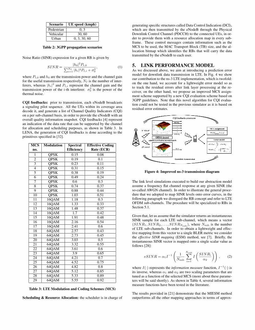
5. LINK PERFORMANCE MODELAs we discussed above, we aim at introducing a prediction errormodel for downlink data transmission in LTE. In Fig. 4 we showour contribution to the ns-3 LTE implementation, which is twofold:on the one hand, we account for a lightweight error model so asto track the residual errors after link layer processing at the re-ceiver, on the other hand, we propose an improved MCS assign-ment scheme supported by a new CQI evaluation scheme based on3GPP guidelines. Note that this novel algorithm for CQI evalua-tion could not be tested in the previous simulator as it is based onresidual error estimates.
Figure 4: Improved ns-3 transmission diagram
The link level simulations executed to build our abstraction modelassume a frequency flat channel response at any given SINR (theso-called AWGN channel). In order to illustrate the general proce-dure that we adopted to map SINR levels onto error curves, in thefollowing paragraph we disregard the RB concept and refer to LTEOFDM sub-channels. The procedure will be specialized to RBs inSection 5.1.
Given that, let us assume that the simulator returns an instantaneousSINR sample for each LTE sub-channel, which means a vector(SINR1, SINR2, . . . , SINRNsub), where Nsub is the numberof LTE sub-channels. In order to obtain a lightweight and effec-tive mapping from this vector to a single BLER metric we considerthe effective SINR mapping (ESM) method, see [7]. Briefly, theinstantaneous SINR vector is mapped onto a single scalar value asfollows [28]:
eSINR = α1I−1
(1
Nsub
Nsub∑i=1
I
(SINRi
α2
)), (2)
where I(·) represents the information measure function, I−1(·) isits inverse, whereas α1 and α2 are two scaling parameters that aretuned as a function of the selected MCS (more about these parame-ters will be said shortly). As shown in Table 4, several informationmeasure functions have been tested in the literature.
The results provided in [21] demonstrate that the MIESM methodoutperforms all the other mapping approaches in terms of approx-

Effective SINR Mapping Information MeasureCapacity (CESM) [9] I(x) = log2(1 + x)
Logarithmic (LESM) [8] I(x) = log10(x)Exponential (EESM) [5] I(x) = e−x
Mutual Information (MIESM) [6] I(x) = MI(x)
Table 4: Information measure functions tested in the literature
imation accuracy for the BLER curves. Thus, we adopted the Mu-tual Information (MI) metric for our implementation.
5.1 MIB MappingAs reported in [7], the Mutual Information per coded Bit (MIB) canbe approximated through the following function:
J(t) '
{a1t
3 + b1t2 + c1t, t < 1.6363
1− e(a2t3+b2t
2+c2t+d2), 1.6363 ≤ t ≤ ∞, (3)
where the parameters have been obtained through numerical fittingand are reported in the following Table 5.
0.001 ≤ t < 1.6363 1.6363 ≤ t ≤ 1000
a1 = −0.04210661 a2 = 0.00181492b1 = 0.209252 b2 = −0.142675c1 = −0.00640081 c2 = −0.0822054– d2 = 0.0549608
Table 5: J-function approximation parameters
Specifically, it has been demonstrated [7] that the MIB of any mod-ulation m can be approximated as a mixture of J(·) functions asfollows:
Im(x) =
0, x < 0.001∑K
k=1 αkJ(βk√x), 0.001 ≤ x ≤ 1000
1, x > 1000
, (4)
where∑K
k=1 αk = 1 for some K ≥ 1 and the argument x is theSINR associated with the transmission channel under study. Wenote that for x < 0.001, i.e., SINR smaller than -30 dB, the mu-tual information is fixed to 0, whereas for x > 1000, that is SINRbigger than 30 dB, the mutual information is assumed to be alwaysequal to 1. Numerical fittings have been carried out (see again [7])to obtain K, αk and βk for QPSK, 16-QAM and 64-QAM, as re-ported in the following Table 6.
Modulation m MIB function Im(x), 0.001 ≤ x ≤ 1000
QPSK J(2√x) (exact)
16-QAM 12J(0.8
√x) + 1
4J(2.17
√x) + 1
4J(0.965
√x)
64-QAM 13J(1.47
√x) + 1
3J(0.529
√x) + 1
3J(0.366
√x)
Table 6: Numerical approximations for MIB mapping
Next, we specialize Eq. (2) to the case of practical interest whereSINR values are acquired for each resource block. Let SINRn
be the instantaneous SINR value associated with a given RB n,where n = 1, 2, . . . , N and N is the number of RBs allotted to theuser. According to the above discussion, the function Im(x) can beused to map SINRn onto the corresponding mutual informationdomain, where m is the adopted modulation scheme. Note thatthe argument x corresponds to SINRn and in LTE, for each sub-frame, the same modulation is picked for all RBs. Given all that, the
−9 −8.5 −8 −7.5 −7 −6.5 −6 −5.5 −5 −4.5 −4 −3.510
−2
10−1
100
SNR [dB]
BL
ER
TB = 6000 (AWGN)
TB = 6000 (estimated)
TB = 4000 (AWGN)
TB = 4000 (estimated)
TB = 2560 (AWGN)
TB = 2560 (estimated)
TB = 1024 (AWGN)
TB = 1024 (estimated)
TB = 512 (AWGN)
TB = 512 (estimated)
TB = 256 (AWGN)
TB = 256 (estimated)
TB = 160 (AWGN)
TB = 160 (estimated)
TB = 104 (AWGN)
TB = 104 (estimated)
TB = 40 (AWGN)
TB = 40 (estimated)
Figure 5: BLER for MCS 1
Mean Mutual Information per coded Bit (MMIB) can be obtainedas follows:
MMIB =1
N
N∑n=1
Im(SINRn) , (5)
where N is the number of RBs assigned to a specific user and m isthe modulation that this user is exploiting. To sum up, the modelstarts by evaluating the mutual information value for each RB fromthe corresponding SINR samples. Subsequently, the MMIB is com-puted by averaging (effective SINR mapping) the correspondingmutual information values as per Eq. (5).
5.2 BLER predictionThe data at the MAC layer of the LTE protocol stack (right abovethe LTE PHY) is arranged in Transport Blocks (TB), whose sizedepends on the specific configuration of the underlying PHY. TBsare split into a number of CBs which are independently encodedby the turbo encoder at the PHY layer. Each CB is then encodedand transmitted over the channel exploiting the N RBs allotted tothe user, see Section 4. In this section we show how to efficientlycompute the Transport BLock Error Rate (TBLER) from the resultsof Section 5.1.
For the moment, let us focus on the i-th CB of a given TB. As men-tioned in Section 3, link-level simulations (whose results were ob-tained using the Vienna LL simulator) have been used to obtain thePHY-layer performance in terms of BLER vs SINR over AWGNchannels, accounting for the configuration of the PHY-layer turboencoder in terms of Code Block (CB) length and selected MCS.The 3GPP standard has been considered to assess the correct CBsizes in the simulations, according to [4]. As an example, the dot-ted lines in Figs. 5 and 6 show the BLER as a function of SINR forMCS 1 and 29, respectively. These curves have been calculated of-fline considering the actual LTE PHY layer procedures. As can beseen from these plots, the CB size highly impacts the actual BLERperformance for a given MCS.
As mentioned above, the selected CB i is transmitted over the chan-nel using the N RBs that are assigned to the user. At the receiverside, a reference SINR value1 is made available by our ns-3 sys-tem level simulator for each of these RBs, returning the SINR vec-1We assume no frequency selectivity among the 12 sub-carrierscomposing the resource block.

18 18.5 19 19.5 20 20.510
−2
10−1
100
SNR [dB]
BL
ER
TB = 6000 (AWGN)
TB = 6000 (estimated)
TB = 4000 (AWGN)
TB = 4000 (estimated)
TB = 2560 (AWGN)
TB = 2560 (estimated)
Figure 6: BLER for MCS 29
tor (SINR1, SINR2, . . . , SINRN ), as discussed in Section 3.From here, we obtain the MMIB metric using Eq. (5), as explainedin Section 5.1. This MMIB corresponds to an equivalent SINR forthe transmission of CB i over the allotted RBs. As a last step to ob-tain the residual error rate of CB i, we need to map its MMIB ontothe corresponding BLER, which is referred to here as CBLERi.This is done according to the following procedure.
In order to reduce the computational burden at simulation time asmuch as possible, an approximation based on the Gaussian cumu-lative model has been adopted. According to this, the estimatedBLER curves as a function of MMIB are parameterized as follows:
CBLERi(x) =1
2
[1− erf
(x− bS,M√
2cS,M
)], (6)
where x is the MMIB associated with CB i, bS,M represents the socalled “transition center” and cS,M is the “transition width” of theGaussian cumulative distribution. S is the code block size and Mis the MCS, which dictates the actual transmission rate, as shownin Table 3. What we did at this point, was to find suitable pairs(bS,M , cS,M ) for each MCS and code size. We did so through nu-merical fitting so that the curves from Eq. (6) would match thoseobtained from the Vienna LL simulator. The result of this proce-dure is shown in Figs. 5 and 6, where the solid curves represent theresult of Eq. (6) where we have used the best fitting (bS,M , cS,M )pair for each MCS and code size. As can be seen from these plots,the approximated BLER from Eq. (6) (solid lines) closely matchthe BLER obtained through the numerical simulation of LTE PHYprocedures (dotted lines).
To sum up, for any given code block i, the correspondingCBLERi
is computed as follows:
1. Obtain the SINR vector (SINR1, SINR2, . . . , SINRN )for CB i.
2. Obtain the MMIB from this SINR vector using Eq. (5).
3. Use the selected CB size S and MCS M to pick the best fit-ting parameters (bS,M , cS,M ) from a lookup table, computedoffline.
4. Use this pair (bS,M , cS,M ) with Eq. (6) to obtain CBLERi.
The overall Transport BLock Error Rate (TBLER) is thus found as:
TBLER = 1−C∏
i=1
(1− CBLERi) , (7)
where C is the number of CBs contained in the TB.
Lookup tables: to limit the computational complexity and thememory space taken by the proposed link abstraction model, weonly considered a subset of CB sizes, i.e., S = {40, 104, 160, 256,512, 1024, 2560, 4000, 6000} bits. This choice is aligned with thetypical performance of turbo codes, where large CB sizes do notstrongly affect BLER performance. However, we note that for CBsizes smaller than 1000 bits, the BLER performance might signif-icantly differ as we vary the block size (up to nearly 3 dB). There-fore, we accounted for an unbalanced quantization of CB sizes inorder to get more accuracy in the critical zone (small code blocks).This is particularly evident from Fig. 5 that shows a similar BLERprofile for large CB sizes (e.g., 2500, 4000 and 6000 bits), whereasthe performance gap increases as the CB size gets smaller. Thus,(bS,M , cS,M ) parameters have been tabulated for all valid combi-nations of MCS and block sizes in set S. We remark that highMCS values with high order modulations and efficient coding rateschemes, such as 64-QAM with an Effective Coding Rate (ECR)of 0.92 (i.e., MCS 29), see Fig. 6, allow for a minimum CB sizeof 2560 bits. The latter is much larger than the minimum size atsmall MCS values, e.g., MCS 1, where the minimum size is 40bits, see Fig. 5. This reflects the fact that turbo coding offers betterperformance as the code block size increases; thus, for high ordermodulations such as MCS 29, small code block lengths are ineffi-cient as the resulting BLER performance is unacceptable.
6. LINK ADAPTATION IMPROVEMENTLink adaptation plays a fundamental role in modern wireless com-munications systems, which need to face issues such as strong in-terference from multiple users and their mobility, which makes thewireless channel frequency selective. These facts are coped withby LTE adaptive modulation and coding algorithms. Focusing onthe downlink scenario, AMC has the role of tracking the perceivedSINR and sending back to the base station (eNodeB) a so calledCQI report. Hence, periodically, the UE reports to the eNodeB asingle CQI value for all the RBs (the so called wideband CQI). Thisinformation is a “compressed” representation of the quality expe-rienced by the UE in a specific sub-frame and is used at the basestation side for the selection of the MCS. This process is continu-ously executed so as to adapt to channel and network dynamics.
In this section, we propose a SINR to CQI mapping approach basedon the link error abstraction model presented above. As a com-peting approach we consider the algorithm that is currently imple-mented in the LENA ns-3 simulator, which is inspired by the spec-tral efficiency concept, see also [30].
Spectral efficiency-based approach: consider the generic RB i,and let SINRi be the corresponding SINR value, in linear units.We obtain the spectral efficiency ηi of RB i using the followingequations:
Γ = − ln (5 BER)
1.5, (8)
ηi = log2
(1 +
SINRi
Γ
), (9)
where BER is the Bit Error Rate and Γ is the so called SNR gap, asit models the discrepancy between practical implementations and

information-theoretic results.
Upon the calculation of ηi, which lies in the continuous interval[0.15, 5.55] (see Table 3), the procedure described in [1] is used toderive the corresponding CQI, which is a quantized version of ηi.
Algorithm 1 CQI assignment performed by each UE. Prior to thiscomputation, the users decode the pilot sequence sent by the eN-odeB in order to get all the RB SINR samples that are needed toretrieve the predicted error rate.
Require: Target TBLER (TBLERth), SINRUE
for i = 1→ NUE doMCS ← 29while MCS > 0 doTBLERi ← GetTbError(SINRi,MCS)if TBLERi < TBLERth thenbreak
elseMCS −−
end ifend whileCQIi ← GetCorrespondingCqi(MCS)
end for
Error model-based approach: this model relies on the exploita-tion of our link abstraction model. Thanks to this approach, wecan dynamically select the MCS that better complies with a giventarget transport block error rate for the connection, referred to asTBLERth. In the following, we describe our improved CQI eval-uation procedure by abstracting away from the actual implemen-tation details, i.e., on the actual representation of CQI values (atthe receiver, e.g., number of CQI levels, etc.) and the subsequentmapping of these CQIs onto a suitable MCS (which is done at theeNodeB).
Our procedure, which is reported in Algorithm 1, works as follows.Periodically, each UE computes its received power spectrum pro-file, i.e., a SINR sample is acquired for each possible RB.2 For anygiven user i = 1, 2, . . . , NUE , it starts from MCS 29, which cor-responds to the most aggressive transmission scheme and evaluatesthe TBLER performance considering a transport block composedof all possible LTE RBs. The transport block error rate for user i,TBLERi, is estimated through Eq. (6), taking as input the vec-tor of SINRs for the selected user, SINRi, and the MCS that weare currently evaluating. If TBLERi is larger than or equal to thetarget BLER defined by 3GPP (i.e., 0.1) [4], we keep on search-ing for a better (less aggressive) MCS, the procedure stops other-wise. Thus, the corresponding CQI is obtained in order to satisfythe spectral efficiency constraints defined by the standard [4] andreported in Table 7.
From eNodeB’s perspective, the CQI mapping to MCS can be re-turned by inverting the mapping of Table 7.
7. SIMULATION RESULTSIn the following we provide some technical results for selected LTEscenarios. Our main goals are: 1) to illustrate the usability of theproposed link abstraction model, and 2) to prove the efficiency ofthe link adaptation improvement proposed in Section 6. In Table 8we report the considered system parameters.
2In this case, all RBs allowed by the selected LTE channel band-width are accounted for, according to Table 1.
CQI Index Modulation Spectralno. Efficiency0 out of range -1 QPSK 0.15232 QPSK 0.23443 QPSK 0.37704 QPSK 0.60165 QPSK 0.87706 QPSK 1.17587 16QAM 1.47668 16QAM 1.91419 16QAM 2.406310 64QAM 2.730511 64QAM 3.322312 64QAM 3.902313 64QAM 4.523414 64QAM 5.115215 64QAM 5.5547
Table 7: CQI coding table
−20 −15 −10 −5 0 5 10 15 20 25 300
0.1
0.2
0.3
0.4
0.5
0.6
0.7
0.8
0.9
1
SNR [dB]
MIB
QPSK
16 − QAM
64 − QAMMCS 18 64−QAM MIB = 0.761
MCS 17 16−QAM MIB = 0.975
Figure 7: Example 1 - MI extraction
1) Error model: we consider a downlink transmission from aneNodeB to a single static UE. For the wireless channel, we accountfor a Friis free-space propagation model, but note that the conclu-sions that we draw here are general and apply to more sophisticatedmodels as well. The UE is placed 2150 meters away from the eN-odeB and, according to the considered propagation loss model, itexperiences a SNR of 15.1 dB for all its RBs.
We first evaluate the BLER performance resulting from the selec-tion of a “safe” transmission scheme, MCS 17, which correspondsto 16QAM (4 bits per OFDM symbol). As we now show, for thisMCS the estimated error rate (through Eq. (6)) is below the stan-dard TBLER threshold of TBLERth = 0.1. First of all, we ex-tract the mutual information value associated with the experiencedSNR, as shown in Fig. 7 (where we plot the approximation func-tions of Table 6). According to [4], from the selected MCS andthe maximum number of assignable RBs (see Table 1) the TB sizeis 7272 bits (including the header). Following [4], the TB is splitinto two code blocks, CB1 and CB2, of size 3684 and 3584 bits,respectively. As shown in Fig. 8, these code sizes are mapped ontothe closest CB size in set S. In fact, as per our discussion in Sec-tion 5.2, in our ns-3 simulator fitting parameters are only stored

PHY ConfigurationParameter ValueFrequency 2.1 GHz
Channel Bandwidth 5 MHzPropagation Model Friis free-spaceNumber of RBs 25RBbandwidth 180 kHzRBsubcarriers 12
RBOFDMsymbols 14eNodeB TX power 30 dBm
Noise figure (F) 5Noise spectral density (N0) −174 dBm/Hz
Table 8: Main system parameters
Figure 8: Example 1 - TBLER computation
for a subset of all possible CB sizes. Thus, the resulting CB sizethat will be used for the prediction of the CBLER performance is2560 bits. Now, using the bS,M and cS,M parameters associatedwith the latter code block size and the previously extracted MI withEqs. (6) and (7), we obtain an estimated transport block error rateof TBLER = 0.
Next, we try to allocate a more aggressive modulation and codingscheme, MCS 18, for which the modulation order amounts to 6 bitsper OFDM symbol (64QAM). Thus, we repeat the procedure illus-trated in the previous paragraph, obtaining the mutual informationMI, and the fitting parameters bS,M and cS,M . These quantities, to-gether with Eqs. (6) and (7) return TBLER = 0.14, which meanthat MCS 18 is not compatible with the considered error require-ments.
2) Link adaptation: we now consider a scenario with a singleUE, where we vary its distance from the eNodeB. This leads toSNR values ranging from about 2 to 30 dB. Also, we consider thestandard target transport block error rate of TBLER = 0.1. InFig. 9, we show the effective spectral efficiency as a function ofthe SNR for the spectral efficiency-based (SE_MCS) and the error-based (EM_MCS) MCS selection schemes. The effective spectralefficient metric reflects the actual bits per second per unit of fre-quency that are successfully transmitted from the eNodeB to theUE, by also accounting for the residual error after PHY-layer pro-cessing. As can be seen from Fig. 9, EM_MCS outperforms thecurrent approach, at all SNR levels. This indicates that SE_MCS
0 5 10 15 20 25 300
1
2
3
4
5
6
SNR [dB]
Eff
ecti
ve
Spec
tral
Eff
icie
ncy
(bps/
Hz)
SE_MCS
EM_MCS
Figure 9: MCS assignment comparison
tends to be too conservative, even though a more aggressive tech-nique can be used while still adhering to the target error require-ments.
8. CONCLUSIONS & FUTURE WORKIn this work we introduced a link abstraction model for the system-level simulation of downlink traffic in LTE networks using ns-3.Our objective here has been to provide a lightweight but still ac-curate procedure for the computation of the residual errors, afterPHY-layer processing, without having to go through the detailedsimulation of LTE PHY procedures. Toward this end, we com-bined Mutual Information-based multi-carrier compression metricswith Link-Level performance curves matching. This allowed us toobtain pre-calculated lookup tables, which can be used in an onlinefashion to track residual bit errors after physical layer modulationand coding procedures. In addition, we have proposed a ChannelQuality Indicator evaluation procedure which can be used as partof the LTE Adaptive Modulation and Coding scheme, showing itssuperiority in terms of achievable spectral efficiency with respect tocurrent ns-3 solutions. As future work we plan to investigate algo-rithms for resource allocation, especially targeting the transmissionof streaming flows over LTE networks.
9. REFERENCES[1] 3GPP R1-081483, "Conveying MCS and TB size via
PDCCH".[2] 3GPP TS 36.101, "E-UTRA User Equipment (UE) radio
transmission and reception".[3] 3GPP TS 36.104, "E-UTRA Base Station (BS) radio
transmission and reception".[4] 3GPP TS 36.213, "E-UTRA Physical layer procedures".[5] 3GPPTR 25.892, "Feasibility Study for OFDM for UTRAN
enhancement (release6)". v1.1.0, (2004-03).[6] ERICSSON. "Effective SNR mapping for modelling frame
error rates in multiple-state channels".3GPP2-C30-20030429-010, April 2003.
[7] IEEE 802.16 Broadband Wireless Access Working Group,Evaluation Methodology Document (EMD).
[8] IEEE802.11-04/0269, "PHY abstraction based on PERprediction". March 2004.
[9] IST-2000-30116 FITNESS Project, "MTMR BasebandTransceivers Needs for Intra-system and Inter-system(UMTS/WLAN) Reconfigurability". Deliverable 3.3.1.

[10] LENA documentation, http://lena.cttc.es/manual/.[11] The LTE-EPC Network Simulator (LENA) project,
http://iptechwiki.cttc.es/LTE-EPC_Network_Simulator_(LENA).
[12] The Network Simulator - ns-2, http://www.isi.edu/nsnam/ns/.[13] The Network Simulator - ns-3, http://www.nsnam.org/.[14] The Vienna LTE Simulators,
http://www.nt.tuwien.ac.at/about-us/staff/josep-colom-ikuno/lte-simulators/.
[15] A. Sayenko, O. Alanen, H. Martikainen, V. Tykhomyrov andO. Puchko. WINSE: WiMAX NS-2 Extension. InSIMUTools, Rome, Italy, March 2009.
[16] B. Sadiq, R. Madan and A. Sampath. Downlink Schedulingfor Multiclass Traffic in LTE. In EURASIP Journal onWireless Communications and Networking, volume 2009,2009.
[17] N. Baldo and M. Miozzo. Spectrum-aware Channel and PHYlayer modeling for ns3. In International Workshop onNetwork Simulation Tools (NSTOOLS), October 2009.
[18] N. Baldo, M. Miozzo, M. Requena-Esteso, andJ. Nin-Guerrero. An Open Source Product-Oriented LTENetwork Simulator based on ns-3. In ACM InternationalConference on Modeling, Analysis and Simulation ofWireless and Mobile Systems, November 2011.
[19] N. Baldo, M. Requena-Esteso, J. Nin-Guerrero, andM. Miozzo. A new model for the simulation of the LTE-EPCdata plane. In Workshop on ns-3 (WNS3), in conjunction withICST SIMUTOOLS, March 2012.
[20] Y. Blankenship, P. Sartori, B. Classon, V. Desai, andK. Baum. Link error prediction methods for multicarriersystems. In IEEE Vehicular Technology Conference,VTC-Fall, volume 6, September 2004.
[21] K. Brueninghaus, D. Astely, T. Salzer, S. Visuri, A. Alexiou,S. Karger, and G.-A. Seraji. Link performance models forsystem level simulations of broadband radio access systems.In IEEE PIMRC, September 2005.
[22] C. Mehlfuhrer, J. Colom Ikuno, M. Simko, S. Schwarz, M.Wrulich and M. Rupp. The Vienna LTE simulators: Enablingreproducibility in wireless communications research.EURASIP Journal on Advances in Signal Processing,2011(1), July 2011.
[23] G. Piro, L.A. Grieco, G. Boggia, F. Capozzi and P. Camarda.Simulating LTE Cellular Systems: An Open-SourceFramework. Vehicular Technology, IEEE Transactions on,pages 498–513, February 2011.
[24] H. Holma and A. Toskala. WCDMA for UMTS: Radio Accessfor Third Generation Mobile Communications. John Wiley &Sons, third edition, 2004.
[25] J. Fan, Q. Yin, G.Y. Li, B. Peng and X. Zhu. MCS Selectionfor Throughput Improvement in Downlink LTE Systems. InInternational Conference on Computer Communications andNetworks (ICCCN), August 2011.
[26] M. Miozzo and F. Bader. Accurate Modelling of OFDMATransmission Technique using IEEE 802.16mRecommendations for WiMAX Network Simulator Design.In ICST Conference on Mobile Networks and Management(MONAMI), Santander, Spain, September 2009.
[27] C. Mehlfuhrer, M. Wrulich, J. C. Ikuno, D. Bosanska, andM. Rupp. Simulating the Long Term Evolution PhysicalLayer. In European Signal Processing Conference(EUSIPCO 2009), August 2009.
[28] M. Moisio and A. Oborina. Comparison of Effective SINRMapping with Traditional AVI Approach for Modeling
Packet Error Rate in Multi-State Channel. In NextGeneration Teletraffic and Wired/Wireless AdvancedNetworking, 2006.
[29] G. Piro, N. Baldo, and M. Miozzo. An LTE Module for thens-3 Network Simulator. In Workshop on ns-3 (WNS3), inconjunction with ICST SIMUTOOLS, March 2011.
[30] H. Seo and B. G. Lee. A proportional-fair power allocationscheme for fair and efficient multiuser OFDM systems. InIEEE GLOBECOM, December 2004.
[31] S. Sesia, I. Toufik, and M. Baker. LTE: The UMTS LongTerm Evolution - from Theory to Practice. John Wiley &Sons, second edition, 2011.
[32] SmallCell-Forum. LTE MAC Scheduler InterfaceSpecification v1.11, Oct. 2010.
[33] E. Tuomaala and H. Wang. Effective sinr approach of link tosystem mapping in ofdm/multi-carrier mobile network. IEEConference Publications, 2005:140–140, 2005.
[34] WiMAX Forum. WiMAX System Evaluation MethodologyDocument. Version 1.0, January 2007.