Embed Size (px)
Citation preview

CommuniCation
1703878 (1 of 7) © 2017 WILEY-VCH Verlag GmbH & Co. KGaA, Weinheim
www.advmat.de
A Lithography-Free and Field-Programmable Photonic Metacanvas
Kaichen Dong, Sukjoon Hong, Yang Deng, He Ma, Jiachen Li, Xi Wang, Junyeob Yeo, Letian Wang, Shuai Lou, Kyle B. Tom, Kai Liu, Zheng You, Yang Wei, Costas P. Grigoropoulos, Jie Yao,* and Junqiao Wu*
DOI: 10.1002/adma.201703878
to fulfill the functionality of an optical reconfigurable system; on the other hand, probing into the time-resolved observation of photonic phenomena requires real-time evolution of those mathematical opera-tors. As such, rewritability, with successful examples in other fields like field-pro-grammable gate arrays (FPGA),[2] would create new optical functionalities via (re)compilation of photonic operators,[3] and thus inevitably attracts vast attention in the field of photonics. Previous attempts at realizing the reconfigurability used micro/nanomechanical metamaterials,[4–6] liquid crystals[7] or amorphous-crystalline phase-transition materials,[8] which are limited in terms of functionality, pixel density, efficiency, fabrication/reconfigu-ration cost or high working temperature (>623 °C).[9] It is much desired to utilize
phase-transition materials to reconfigure photonic elements in a fast, scalable, cost-effective, and lithography-free way at or near room temperature.
In this work, we present an all-solid, rewritable metacanvas for photonic applications, on which arbitrary photonic devices can be rapidly and repeatedly written and erased for real-time
The unique correspondence between mathematical operators and photonic elements in wave optics enables quantitative analysis of light manipulation with individual optical devices. Phase-transition materials are able to provide real-time reconfigurability of these devices, which would create new optical functionalities via (re)compilation of photonic operators, as those achieved in other fields such as field-programmable gate arrays (FPGA). Here, by exploiting the hysteretic phase transition of vanadium dioxide, an all-solid, rewritable metacanvas on which nearly arbitrary photonic devices can be rap-idly and repeatedly written and erased is presented. The writing is performed with a low-power laser and the entire process stays below 90 °C. Using the metacanvas, dynamic manipulation of optical waves is demonstrated for light propagation, polarization, and reconstruction. The metacanvas supports physical (re)compilation of photonic operators akin to that of FPGA, opening up possibilities where photonic elements can be field programmed to deliver complex, system-level functionalities.
Reconfigurable Photonic Platforms
Mathematical operators are generally used in wave optics to quantify the light manipulation of photonic devices, and dif-ferent photonic devices correspond to specifically fixed math-ematical operators,[1] which indeed leads to principal and experimental limitations. On the one hand, in situ modifica-tion of the corresponding mathematical operators is necessary
Dr. K. Dong, Y. Deng, Dr. X. Wang, S. Lou, K. B. Tom, Prof. J. Yao, Prof. J. WuDepartment of Materials Science and EngineeringUniversity of CaliforniaBerkeley, CA 94720, USAE-mail: [email protected]; [email protected]. K. Dong, K. B. Tom, Prof. J. Yao, Prof. J. WuMaterials Sciences DivisionLawrence Berkeley National LaboratoryBerkeley, CA 94720, USADr. K. Dong, Prof. Z. YouState Key Laboratory of Precision Measurement Technology and InstrumentsDepartment of Precision InstrumentTsinghua UniversityBeijing 100084, P. R. ChinaProf. S. Hong, Prof. J. Yeo, L. Wang, Prof. C. P. GrigoropoulosDepartment of Mechanical EngineeringUniversity of CaliforniaBerkeley, CA 94720, USA
The ORCID identification number(s) for the author(s) of this article can be found under https://doi.org/10.1002/adma.201703878.
Prof. S. HongDepartment of Mechanical EngineeringHanyang University55 Hanyangdaehak-ro, Sangnok-gu, Ansan, Gyeonggi-do 15588, Republic of KoreaProf. H. Ma, J. Li, Prof. Y. WeiDepartment of Physics and Tsinghua-Foxconn Nanotechnology Research CenterTsinghua UniversityBeijing 100084, P. R. ChinaProf. J. YeoDepartment of PhysicsKyungpook National University80 Daehak-ro, Bukgu, Daegu 41566, Republic of KoreaProf. K. LiuState Key Laboratory of New Ceramics and Fine ProcessingSchool of Materials Science and EngineeringTsinghua UniversityBeijing 100084, P. R. China
Adv. Mater. 2018, 30, 1703878

© 2017 WILEY-VCH Verlag GmbH & Co. KGaA, Weinheim1703878 (2 of 7)
www.advmat.dewww.advancedsciencenews.com
manipulation of light waves. Different patterns can be written and erased on the same metacanvas successively. The writing is performed with a low-power laser and the entire process stays below 90 °C. Dynamic manipulation of optical waves is demonstrated with the metacanvas, specifically light propaga-tion, polarization, and reconstruction. The metacanvas sup-ports physical (re)compilation of photonic operators akin to that of FPGA, thus realizing the in situ modification of the corresponding mathematical operators of the metacanvas. This dynamic optical system without moving parts opens pos-sibilities where photonic elements can be field programmed to deliver complex, system-level functionalities.
The metacanvas is realized using the hysteretic metal–insulator phase transition (MIT) of polycrystalline vanadium dioxide (VO2) films. Figure 1a shows the schematic of a meta-canvas being micropatterned with a focused laser beam. VO2 undergoes a temperature-driven, reversible transition from the insulating (I) to the metallic (M) phase when heated above its transition temperature (Tc = 68 °C).[10] These two phases differ drastically in their physical properties: the electron den-sity (1.9 × 1023 cm−3 for the M-phase vs 1.9 × 1019 cm−3 for the I-phase), relative dielectric constant (−35 + 119i vs 4.9 near the operation wavelength of 10.6 µm in this work), and color (dark green vs bright yellow under white light illumination) are all dis-tinct,[10,11] thus attracting much attention in various fields.[12–14] These contrasts, together with the MIT hysteresis of polycrys-talline VO2 films, lay the material foundation that enables the all-solid metacanvas for nonvolatile patterning and erasing.
As illustrated in Figure 1b, we first globally heat the VO2 film from room temperature (cooler than Point A) to Tc (Point B), and the entire film is still in the I-phase. Subsequently, a laser is focused onto the film to locally heat the VO2 to the M-phase (Point C). When the laser is turned off or moves to other regions, the laser-heated region will still stay in the M-phase (Point D) owing to the hysteresis.[15] Hence, a nonvola-tile M-phase pattern is written onto the I-phase film. The pat-tern can easily be erased by reducing the global temperature of the entire film beyond the hysteresis (e.g., to Point A). Upon reheating to Point B, the film is reset and ready for rewriting a new pattern in the same region. This process is illustrated in Figure 1c, as well as shown in Video S1 (Supporting Infor-mation). As such, nearly arbitrary patterns of the M-phase can be written, erased, and rewritten onto the I-phase film, hence forming a canvas to “field program” various metaphotonic elements.
Such a rewritable metacanvas is ideal to physically realize mathematical operators for the manipulation of light. This pro-cess is similar in spirit to compilation in electrical engineering: to realize a desired logic in the form of a software program, it is compiled into FPGA using an assembly language. In such a process, the speed of compilation and the programmability of FPGA are critically important. In analogy, to realize the desired mathematical operator to manipulate light, it is rapidly[16] compiled onto the metacanvas using the “photonic assembly language” (Figure 1d), which can be optical gratings,[17,18] metasurfaces,[8,19–22] holography,[23,24] metatronics,[25] etc.
Adv. Mater. 2018, 30, 1703878
Figure 1. A rewritable metacanvas. a) Schematic of laser writing different photonic operator patterns on a metacanvas. b) Temperature-dependent resistance of a VO2 film, where the transition temperature (Tc) is denoted by a vertical dashed line. Insets A and B: Unpatterned VO2 film (all in I-phase). Inset D: The VO2 film (global temperature kept at Tc) is laser written with a pattern of a bear in the M-phase. c) Optical images from writing and erasing process on the metacanvas: i–iii) a pattern of a bear (M-phase) is written onto an I-phase VO2 film, iv,v) then erased by decreasing the global temperature, vi) and another pattern of the word “METACANVAS” is written subsequently. d) Diagram showing the mathematical matrix (F) is compiled onto a metacanvas in the form of a photonic operator for manipulation of light waveform (II). e) Schematic of a metacanvas programmed as a beam steerer with a steering angle ϕ. Inset: Optical image of the beam steering phase array compiled on the metacanvas. f) Normalized, measured light intensity as a function of the propagation direction angle ϕ. Scale bar is 100 µm in (b) and (c), and 10 µm in (e).

© 2017 WILEY-VCH Verlag GmbH & Co. KGaA, Weinheim1703878 (3 of 7)
www.advmat.dewww.advancedsciencenews.com
Therefore, the metacanvas is analogous to the FPGA in three aspects: the compilation of mathematical logics into hardware to suit different applications; the resultant multifunctionalities within one single device; and the real-time reprogrammability after the device is already deployed. Unlike previous litho-graphically made VO2 devices that can only be switched ON/OFF with permanent patterns and fixed functionalities,[26–36] the lithography-free metacanvas is fully reconfigurable in terms of both patterns and functionalities (see Section S2 in the Supporting Information for detailed comparison). As such, the rapid, cost-effective, and reversible compilation of photonic operators on the rewritable metacanvas with lithography-free, micrometer-sized features potentially enables a rich collection of photonics research and applications. Note that the thickness of the VO2 film used is only 200 nm and the probe beam wave-length is 10.6 µm, forming a wavelength-thickness ratio as high as 53 for all the photonic operators compiled. The writing beam used in the following experiments is a 532 nm contin-uous laser with a power around 1 mW and a diameter <1 µm, such that a feature size of ≈1 µm is achieved. Here, we start by dynamically compiling a beam steering operator[20,37,38] on the metacanvas as a proof of concept, based on which we show a more general prototype for a reconfigurable photonic system. Finally, we develop the concept of and demonstrate a physical simulator utilizing the fast (re)compilation of operators on the metacanvas.
Electromagnetic phase arrays have found various applica-tions ranging from radar, communication,[37] biomedical sci-ences,[39] holography,[23,24] to optical tweezers.[40] Currently, large-scale integrated phase array has been reported,[38] but a cost-effective way to implement large-scale, lithography-free, and rapidly reconfigurable phase arrays is much desired to boost these applications. Here, we first test a basic function of the phase array, beam steering. Figure 1e shows the dia-gram of the beam steering process with the metacanvas. The designed phase array is compiled onto the metacanvas, which steers the input light beam to an angle of ϕi as well as changes the handedness of the steered beam.[24] In the experiment, a steered beam was indeed observed along the designed direc-tion (Figure 1f). As we erased the phase array on the meta-canvas by decreasing the global temperature, the steered beam vanished, so a new photonic operator can be compiled after-ward onto the same metacanvas for beam steering in different directions, thus verifying the (re)compilation of operators on the metacanvas.
As a versatile platform capable of “free-style” (re)compila-tion of operators, the metacanvas can go beyond device-level applications such as the beam steerer and enable construction of a comprehensively reconfigurable photonic system. Here, we demonstrate a prototype of such reconfigurable system using two metacanvases for time-resolved observation of dynamic transitions. Transitions between physical phenomena have been heavily investigated in attempt to reveal the other-wise hidden dynamics in various contexts, such as quantum systems[41] and topological phase transition.[42] However, in photonic systems, it is rather difficult or even impossible to experimentally achieve smooth transitions without interrupting the optics. Aided with in situ programming capabilities, a metacanvas-based system enables real-time reconfiguration of
photonic operators to manipulate light, thus opening up new opportunities for resolving and probing dynamic transitions. Again as a proof of concept, we use manipulation of structured light with structured devices[43] as an example. Concentric-ring gratings have been studied intensively for exploration of cylindrical vector and orbital angular momentum with possible applications such as tight focusing and structuring of light.[43] A circularly polarized beam transmitting through the grating gen-erates a doughnut-shaped light field with a dark center due to high transmittance of the radial component of the light beam, while a linearly polarized incident beam results in a two-lobe-shaped light field.[43]
The diagram of achieving such transition is shown sche-matically in Figure 2a. Sequentially erasing operators F1 and F2 would enable the transition from II3
to II3
′, and finally II1 . The
definition of the operator Fi, light waveform IIi , and detailed
formulas are summarized in Section S4 in the Supporting Information. The experimental setup is shown in Figure 2b, where two metacanvases are used. The first metacanvas pro-grammed as a linear polarizer (F1) transforms the circularly polarized light (II1
) into linear polarized light (II2 ), which is fur-
ther transformed into a two-lobe pattern (II3 ) by a concentric-
ring grating (F2) compiled on the second metacanvas. Prior to the transition experiment, we separately characterized the performance of the linear polarizer at variable temperatures, which proved that F1 was correctly compiled, functioning, and erasable (Figure 2c). The polarization ratio of this linear polarizer is maximized and equal to 4.5 at Tc and gradually decreases to about 1 at Tc − 15 °C when the pattern is nearly completely erased. The polarization ratio depends on tempera-ture in a way that is in full agreement with the cooling-down curve of conductance derived from Figure 1b (see Section S7 in the Supporting Information), proving that the erasing of F1 indeed arises from the MIT of VO2.[26] The concentric-ring grating was also similarly characterized and its performance was confirmed. As we assembled them as an optical system in Figure 2b, a two-lobe pattern (II3
) was detected, as shown in Figure 2di. When F1 was being erased, we observed a smooth transition from the two-lobe pattern II3
to a doughnut pattern II3
′, thanks to the smooth transition of the light before F2 from linear polarization to circular polarization. The reduced optical contrast of the patterns, which are practically new operators, carries the information of intermediate states. Finally, when F2 was also completely erased, the doughnut pattern vanished and the output returned the light field of II1
since there is no operator acting on it (Figure 2dvii). This process is shown in Video S2 (Supporting Information). We note that what is plotted in Figure 2d is the transmission ratio in order to explic-itly show the pattern (see the Experimental Section). Thus, the metacanvas based optics could enable dynamical transi-tion in optics without physically replacing the optical compo-nents. New photonic operators can be subsequently complied onto these metacanvases, hence realizing system-level recon-figuration, potentially a valuable merit for applications such as optical computing.[44]
To further employ such photonic operator recompilation as demonstrated by the reconfigurable photonic system, we use the metacanvas to experimentally simulate the design of optical elements, thereafter termed as a physical simulator. Physical
Adv. Mater. 2018, 30, 1703878

© 2017 WILEY-VCH Verlag GmbH & Co. KGaA, Weinheim1703878 (4 of 7)
www.advmat.dewww.advancedsciencenews.com
simulation is generally used in engineering projects to evaluate and compensate random errors arising from real-world applica-tions that cannot be precaptured by theoretical calculation or computer simulation[45] but are critical in fields such as holog-raphy. One deep-rooted problem in holography is the mismatch between the designed and experimental results caused by ubiq-uitous experimental errors, such as fabrication error, detector resolution, laser noise, and diffraction distortion.[46] Although numerical full-wave simulation is able to partially solve these problems, the solution is severely limited by the memory size and computation power of the simulating computer. As a result, it has not been possible to simulate large-scale holo-grams with billions of meshes, let alone the random influence of optical setups involved.[47] The metacanvas, with the advan-tages of lithography free, economical, and rapid recompilation,
presents an approach to simulate the hologram with a physi-cally real system, i.e., a physical simulator.
The work flow of physical simulation is depicted in Figure 3a, where the analytically designed hologram Fd is compiled onto a metacanvas to output an experimental holographic image. The difference between the designed (I A
) and the physically simu-lated (IP
) images is analyzed to find the lumped experimental error (Fe). In the next step, a correction (Fe
1− ) is added to the design to compensate Fe, hence achieving the error-corrected output (IP
′ ). Such corrected design (Fd′) can then be applied to
real-world fabrication of holograms. To demonstrate a proof of concept of this process, we compiled onto the metacanvas a computer-generated hologram of an image consisting of two spots, each with the size of a pixel (Figure 3b). The design (i, ii) and the experimental observation (iii) are shown in Figure 3c.
Adv. Mater. 2018, 30, 1703878
Figure 2. Dynamic compilation of operators on the metacanvas. a) Schematic diagram of light manipulation with dynamic control of operators. b) Schematic of the experimental setup. Inset: Optical images of a linear polarizer F1 (top left) or a concentric-ring grating F2 (bottom right) compiled on the metacanvas. Scale bar: 10 µm. c) Evolution of the normalized, polarization-dependent light transmission from the linear polarizer as temperature is decreased from Tc to Tc − 15 °C. d) Transmitted light intensity normalized by the profile of the incident light intensity. i) Two-lobe pattern where the arrow shows the polarization direction. i–iv) Transition from the two-lobe pattern (F1 + F2) to a doughnut pattern (F2 only) when the linear polarizer (F1) is erased. iv–vii) Fading of the doughnut pattern when the concentric-ring grating (F2) is also erased.

© 2017 WILEY-VCH Verlag GmbH & Co. KGaA, Weinheim1703878 (5 of 7)
www.advmat.dewww.advancedsciencenews.com
The experimental result (iii) in Figure 3c shows that the two spots were not separated sufficiently far from each other, resulting in an overlap between the two spots. We then fixed the error by adding one more pixel between the spots (iv, v), which led to a complete separation of the two spots (vi). The com-parison between the design and the experimental data clearly shows the limitation of the analytical designing (Figure 3d). Therefore, by comparing the experimental results to the analyt-ical design, the metacanvas-based physical simulator effectively processes a full-wave simulation breaking the computational limitations, providing a fast, cost-effective, lithography-free approach to optimize metaphotonic elements before their real-world fabrication.
In conclusion, we have exploited the VO2 phase transition to attain real-time reconfigurability and field programmability of photonic devices, and achieved rapid (re)compilation of various photonic operators on the metacanvas for full light manipu-lation in both space and time dimensions. From the high-speed, large-scale, “free-style” writing and erasing, the dynamic compilation of photonic operators has the potential to enable unprecedented applications (e.g., real-time analysis and control
of photonic devices) as well as basic research (e.g., probing into time-dependent optical processes). We note that all the experiments (including Videos S1 and S2 in the Supporting Information) we show in this work were completed with only three VO2 films, which have undergone several tens of damage-free writing–erasing processes under ambient condition, exhib-iting great versatility and stability. Different patterns have been repetitively written and erased on the same film, thus proving the context of rewritability.
The technical specifications of the metacanvas are analyzed as follows: First, the patterns shown in Figures 1e, 2b, and 3b were written at a speed of 0.03–2 mm s−1, depending on the complexity of the patterns. The current writing speed is only limited by the stability of the direct laser writing system, in which high writing speeds result in strong mechanical vibration. Considering the feature size and the laser power (see the Exper-imental Section), the energy cost to pattern the metacanvas is calculated to be ≈600 nJ µm−2, which is higher than the theoret-ical lower bound of the writing power of 0.064 nJ µm−2 because of nonideal optical absorption of the VO2 films as well as heat dissipation. Second, the theoretical lower bound of standby
Adv. Mater. 2018, 30, 1703878
Figure 3. The metacanvas functioning as a holographic physical simulator. a) Diagram showing the image correction process using the physical simulator with schematic images. The first attempt in the physical simulator output (IIP ) includes the lumped experimental error (Fe) and the designed phase distribution (Fd). This error information can then be identified and taken into consideration in the second-round design (F F F=′ −
d e1
d) in the physical simulation to eliminate the error. The corrected phase array (F ′
d) can then be used in real implementation to yield an ideal image as designed. b) Optical images of a hologram compiled on the metacanvas with different magnifications. Note that this hologram consists of the information for the two-spot image and 18° beam steering phase distribution, and thus is different from that in Figure 1e. Scale bar: 100 µm (main) and 10 µm (inset). c) Target two-spot images, the corresponding calculated phase distribution, and the experimental holographic images with i–iii) one-pixel and iv–vi) two-pixel separation. Note that (i) and (iv) only show the middle parts of the full images, and (ii) and (v) have taken the beam steering phase into consideration. d) Comparison between the analytical design and the physical simulator output data along the horizontal dashed lines in the holographic images in (ciii,vi).

© 2017 WILEY-VCH Verlag GmbH & Co. KGaA, Weinheim1703878 (6 of 7)
www.advmat.dewww.advancedsciencenews.com
power of the metacanvas is the heat loss from the sample sur-face to air, as the other heat losses (to solid heat sinks) can be minimized by design for good heat isolation. This is estimated to be ≈700 µW per sample size of 1.28 × 1.28 mm2. Practically, microheaters with a similar geometry can maintain ≈68 °C with a power consumption on the order of ≈10 mW.[48,49] Third, the relaxation time of the metacanvas is limited by the cooling rate rather than the intrinsic phase transition speed of VO2.[16] In the experiment, it was observed that the patterns can be erased in <≈ 1 s at room temperature. In the extreme case that air cooling is the only heat loss, numerical calculation shows that it takes ≈27 s to cool down an Si chip (1 × 1 × 0.5 mm3, imitating the metacanvas) from 68 to 45 °C to erase all M-phase patterns (see Section S9 in the Supporting Information for details).
The performance of the photonic operators compiled on the metacanvas can be further improved by optimizing the feature size and shape, the film thickness, and the material quality. Current limitations for unleashing the full potential of the metacanvas are related to our facilities rather than the metacanvas itself. Further improvements in the metacanvas can be made at least in two aspects: first, switching the laser writing to electrical control of metacanvas will potentially yield a friendlier device footprint for some integrated elec-tronic systems; second, the technology of metacanvas can be applied to other materials with first-order phase transition and a hysteresis akin to that of VO2 films,[50] potentially expanding the spectral range and working condition. In all, aided with more advanced facilities, one can envision to further apply the metacanvas technology for more advanced applications, such as optical computing[44] or fully reconfigurable photonic cir-cuitry.[51] It is also possible to build dynamic optical systems without moving parts, where a wide range of functionalities can be customized in situ by repeatedly programming and coding the metacanvases.
Experimental SectionVO2 Growth and Characterization: VO2 films were deposited onto
double-side polished, undoped Si substrates in a DC magnetron sputtering system using a high-purity vanadium metal target. The sputtering was carried out with a flowing gas mixture (49.7 sccm Ar and 0.3 sccm O2 under 0.55 Pa for 30 min, DC power of 60 W) at room temperature. After the VO2 deposition, it was annealed in a low-pressure O2 atmosphere (3 × 10⁻² mbar) at 450 °C for 10 min to facilitate the crystallization. The resistance hysteresis curve of the VO2 shown in Figure 1b was measured using a probe station and a home-made heating stage with a Lakeshore 325 temperature controller.
Laser Writing: The temperature control (heating and cooling) was achieved using Lakeshore 325 (and/or 321) temperature controller(s) and home-made heating stages which consisted of Pt temperature sensors and Kapton insulated flexible heaters.
For the characterization experiments, an LRS-0532 diode pumped solid-state continuous-wave laser (Laserglow Technologies) was used for the laser writing at 532 nm wavelength. Besides the laser, key components in the direct laser writing system included an Olympus 100 × lens (NA = 0.95, infinity corrected), a nanopositioning stage (Aerotech, ANT130-XY series), and a mechanical shutter (Thorlabs). The laser power irradiated at the VO2 film was 1.14–1.25 mW, with a diameter less than 1 µm. The writing speeds for the polarizers, concentric rings, and the metasurface were 2 mm s−1, 0.05–0.2 mm s−1, and 0.03 mm s−1, respectively. As such, the intrinsic spatial resolution is set by the thermal diffusion length in VO2 and is estimated to be
≈100 nm within the laser exposure time (<40 ms) of the area of 1 µm2, which is on the similar order of the grain size of the VO2 film (Figure S2, Supporting Information). Also, the latent heat of VO2 phase transition helps prevent the leakage. Hence, it can be concluded that finer features can be achieved with advanced writing tools.
For writing the patterns of the bear and the word “METACANVAS”, a 20 × lens (Mitutoyo) was used instead, and the laser power irradiated at the VO2 film was 11.5 mW, which had a diameter of approximately 3 µm. The movement of the nanopositioning stage and the ON/OFF of the mechanical shutter were computer programmed and automatically controlled, as shown in Video S1 (Supporting Information), where a CCD camera was used for in situ observation and recording.
Metacanvas Characterization: A CO2 laser (DIAMOND C-20A, Coherent Inc.), with a waveform generator (33600A series, Keysight Technologies Inc.), was used for generating the 10.6 µm laser radiation in all the characterization experiments. A commercial wire grid linear polarizer (WP25M-IRC, Thorlabs) and a 90° phase retarder (Ophir) were used for the creation of the circularly polarized light. The subsequent integrated power measurement in Figure 2c was carried out using a high-sensitivity thermal power sensor (S401C, Thorlabs), where each data point is the average of 20 measurements continuously recorded at 10 Hz. The mapping of intensity distribution was achieved with pixel-by-pixel scanning: an iris and the power sensor (S401C) were integrated onto a three-axis nanomax stage (Thorlabs) controlled by a three-channel APT benchtop stepper motor controller (BSC203, Thorlabs). Similarly, each data point in the mapping is averaged from 10 consecutive measurements. B-spline interpolation was applied to all the mapping data using Mathematica.
In the beam steering experiment, the circularly polarized light transmitted through the metacanvas programmed as a phase array. A focusing lens was positioned behind the metacanvas. Since the distance between the metacanvas and the lens was equal to its focal length, the steered light was focused at the focal plane on the other side, where a 2D mapping was conducted. After converting the position information at the mapping plane into the steered angle, we obtained data to plot Figure 1f.
For characterization of the metacanvas programmed as a linear polarizer, the generated circularly polarized light went through the metacanvas, another commercial linear polarizer (WP25M-IRC, Thorlabs), and then finally into the power sensor (S401C) for integrated power measurements. The transmittance power was measured as a function of the rotation angle of the commercial linear polarizer. We fitted to the data points with sine functions ( ω ϑ δ= + +sin( )i i i i if A B ) and then normalized them with the value of Bi to plot Figure 2c. In a separate characterization experiment, the metacanvas was programmed as a concentric-ring grating. The commercial linear polarizer (WP25M-IRC) was positioned before the metacanvas to image the two-lobe pattern, while the doughnut pattern was mapped without the commercial linear polarizer, i.e., the circularly polarized light went directly through the metacanvas. We divided the experimentally recorded 2D light intensity map with the input Gaussian beam intensity profile to obtain the 2D transmission ratio map, as shown in Figure S9 in the Supporting Information. Figure 2d was obtained with the same setup as shown in Figure 2b and the same image processing method described above. We thus resolved the transition process (see Video S2 in the Supporting Information) from Figure 2d using interpolation.
Fast Fourier transform was used to generate a hologram, which is shown in Figure 3a,c. To separate the holographic image from the transmitted main peak without degrading the signal-to-noise ratio, we added an extra 18° beam steering phase information to the hologram. The experimental realization of the holography utilized the same setup as the beam steering experiment.
Supporting InformationSupporting Information is available from the Wiley Online Library or from the author.
Adv. Mater. 2018, 30, 1703878

© 2017 WILEY-VCH Verlag GmbH & Co. KGaA, Weinheim1703878 (7 of 7)
www.advmat.dewww.advancedsciencenews.com
AcknowledgementsK.D., S.H., and Y.D. contributed equally to this work. This work was supported by U.S. NSF Grant No. 1608899. The VO2 thin films were grown in the Tsinghua-Foxconn Nanotechnology Research Center at Tsinghua University. Some of the fabrication used facilities in the Electronic Materials Group funded by the Director, Office of Science, Office of Basic Energy Sciences, Material Sciences and Engineering Division of the U.S. Department of Energy under contract number DE-AC02-05CH11231. K.D. acknowledges the China Scholarship Council (CSC, Grant No. 201406210211) for financial support. K.D., Y.D., and J. Yao were also supported by the Bakar fellows program of the University of California, Berkeley. H.M. and Y.W. acknowledge the National Natural Science Foundation of China (Grant No. 51472142). The authors are grateful to Prof. K. Jiang, J. Zhong, Qitong Li, Prof. Z. Hou, Y. Rho, X. Lei, Y. Lv, C. Ko, H. S. Choe, Y. Chen, Quanwei Li, J. Kim, T. Van de Goor, J. Xiao, H. Zhu, Z. Gong, E. Cardona, and S. He for helpful discussions.
Conflict of InterestThe authors declare no conflict of interest.
Keywordshysteretic phase transitions, lithography-free writing, metacanvas, real-time reconfigurability, vanadium dioxide
Received: July 12, 2017Revised: September 27, 2017
Published online: December 11, 2017
[1] A. Gerrard, J. M. Burch, Introduction to Matrix Methods in Optics, Courier Corporation, North Chelmsford, MA 2012.
[2] S. Brown, J. Rose, IEEE Des. Test Comput. 1996, 13, 42.[3] A. Silva1, F. Monticone, G. Castaldi, V. Galdi, A. Alù, N. Engheta,
Science 2014, 343, 160.[4] N. I. Zheludev, E. Plum, Nat. Nanotech. 2016, 11, 16.[5] J.-Y. Ou, E. Plum, J. Zhang, N. I. Zheludev, Adv. Mater. 2016, 28,
729.[6] L. Cong, P. Pitchappa, C. Lee, R. Singh, Adv. Mater. 2017, 29,
1700733.[7] N. I. Zheludev, Science 2015, 348, 973.[8] Q. Wang, E. T. F. Rogers, B. Gholipour, C. Wang, G. Yuan, J. Teng,
N. I. Zheludev, Nat. Photonics 2016, 10, 60.[9] Z. Sun, J. Zhou, R. Ahuja, Phys. Rev. Lett. 2007, 98, 055505.
[10] D. Fu, K. Liu, T. Tao, K. Lo, C. Cheng, B. Liu, R. Zhang, H. A. Bechtel, J. Wu, J. Appl. Phys. 2013, 113, 043707.
[11] M. M. Qazilbash, M. Brehm, G. O. Andreev, A. Frenzel, P. Ho, B. Chae, B. Kim, S. J. Yun, H. Kim, A. V. Balatsky, O. G. Shpyrko, M. B. Maple, F. Keilmann, D. N. Basov, Phys. Rev. B. 2009, 79, 075107.
[12] S. Kumar, M. D. Pickett, J. P. Strachan, G. Gibson, Y. Nishi, R. S. Williams, Adv. Mater. 2013, 25, 6128.
[13] B. Hu, Y. Ding, W. Chen, D. Kulkarni, Y. Shen, V. V. Tsukruk, Z. L. Wang, Adv. Mater. 2010, 22, 5134.
[14] L. Pellegrino, N. Manca, T. Kanki, H. Tanaka, M. Biasotti, E. Bellingeri, A. S. Siri, D. Marré, Adv. Mater. 2012, 24, 2929.
[15] J. Hou, X. Wang, D. Fu, C. Ko, Y. Chen, Y. Sun, S. Lee, K. X. Wang, K. Dong, Y. Sun, S. Tongay, L. Jiao, J. Yao, K. Liu, J. Wu, Small 2016, 12, 3976.
[16] A. Cavalleri, C. Tóth, C. W. Siders, J. A. Squier, Phys. Rev. Lett. 2001, 87, 237401.
[17] K. Aydin, V. E. Ferry, R. M. Briggs, H. A. Atwater, Nat. Commun. 2011, 2, 517.
[18] J. A. Schuller, E. S. Barnard, W. Cai, Y. C. Jun, J. S. White, M. L. Brongersma, Nat. Mater. 2010, 9, 193.
[19] X. Ding, F. Monticone, K. Zhang, L. Zhang, D. Gao, S. N. Burokur, , A. de Lustrac, Q. Wu, C.-W. Qiu, A. Alù, Adv. Mater. 2015, 27, 1195.
[20] N. Yu, P. Genevet, M. A. Kats, F. Aieta1, J. Tetienne, F. Capasso, Z. Gaburro, Science 2011, 334, 333.
[21] H. Zhang, M. Kang, X. Zhang, W. Guo, C. Lv, Y. Li, W. Zhang, J. Han, Adv. Mater. 2017, 29, 1604252.
[22] L. Zhang, S. Mei, K. Huang, C.-W. Qiu, Adv. Opt. Mater. 2016, 4, 818.
[23] X. Ni, A. V. Kildishev, V. M. Shalaev, Nat. Commun. 2013, 4, 2807.[24] L. Huang, X. Chen, H. Mühlenbernd, H. Zhang, S. Chen, B. Bai,
Q. Tan, G. Jin, K. Cheah, C. Qiu, J. Li, T. Zentgraf, S. Zhang, Nat. Commun. 2013, 4, 2808.
[25] Y. Sun, B. Edwards, A. Alù, N. Engheta, Nat. Mater. 2012, 11, 208.[26] J. Rensberg, S. Zhang, Y. Zhou, A. S. McLeod, C. Schwarz,
M. Goldflam, M. Liu, J. Kerbusch, R. Nawrodt, S. Ramanathan, D. N. Basov, F. Capasso, C. Ronning, M. A. Kats, Nano Lett. 2016, 16, 1050.
[27] R. M. Briggs, I. M. Pryce, H. A. Atwater, Opt. Express 2010, 18, 11192.[28] R. Lopez, L. C. Feldman, R. F. Haglund Jr., Phys. Rev. Lett. 2004, 93,
177403.[29] D. W. Ferrara, J. Nag, E. R. MacQuarrie, A. B. Kaye, R. F. Haglund Jr,
Nano Lett. 2013, 13, 4169.[30] J. Y. Suh, E. U. Donev, D. W. Ferrara, K. A. Tetz, L. C. Feldman,
R. F. Haglund Jr., J. Opt. A: Pure Appl. Opt. 2008, 10, 055202.[31] C. McGahana, K. Appavoo, R. F. Haglund Jr., J. Vac. Sci. Technol., B
2013, 31, 06FE01.[32] S. K. Earl, T. D. James, T. J. Davis, J. C. McCallum, R. E. Marvel,
R. F. Haglund Jr., A. Roberts, Opt. Express 2013, 21, 27503.[33] M. Seo, J. Kyoung, H. Park, S. Koo, H. Kim, H. Bernien, B. J. Kim,
J. H. Choe, Y. H. Ahn, H.-T. Kim, N. Park, Q-H. Park, K. Ahn, D. Kim, Nano Lett. 2010, 10, 2064.
[34] D. J. Shelton, K. R. Coffey, G. D. Boreman, Opt. Express 2010, 18, 1330.
[35] D. Y. Lei, K. Appavoo, F. Ligmajer, Y. Sonnefraud, R. F. Haglund Jr, S. A. Maier, ACS Photonics 2015, 2, 1306.
[36] O. L. Muskens, L. Bergamini, Y. Wang, J. M. Gaskell, N. Zabala, C. de Groot, D. W. Sheel, J. Aizpurua, Light Sci. Appl. 2016, 5, e16173.
[37] R. C. Hansen, Phased Array Antennas, Wiley, Hoboken, NJ 1998.[38] J. Sun, E. Timurdogan, A. Yaacobi, E. S. Hosseini, M. R. Watts,
Nature 2013, 493, 195.[39] Z. Yaqoob, D. Psaltis, M. S. Feld, C. Yang, Nat. Photonics 2008, 2, 110.[40] D. G. Grier, Nature 2003, 424, 810.[41] Y. Zhang, T. Chang, B. Zhou, Y. Cui, H. Yan, Z. Liu, F. Schmitt,
J. Lee, R. Moore, Y. Chen, H. Lin, H. Jeng, S. Mo, Z. Hussain, A. Bansil, Z. Shen, Nat. Nanotech. 2014, 9, 111.
[42] C. Yan, J. Liu, Y. Zang, J. Wang, Z. Wang, P. Wang, Z. Zhang, L. Wang, X. Ma, S. Ji, K. He, L. Fu, W. Duan, Q. Xue, X. Chen, Phys. Rev. Lett. 2014, 112, 186801.
[43] J. Zeng, X. Wang, J. Sun, A. Pandey, A. N. Cartwright, N. M. Litchinitser, Sci. Rep. 2013, 3, 2826.
[44] H. J. Caulfield, S. Dolev, Nat. Photonics 2010, 4, 261.[45] J. L. Schwartz, M. A. Peck, C. D. Hall, J. Guid. Control Dyn. 2003,
26, 513.[46] P. Zhou, J. H. Burge, Appl. Opt. 2007, 46, 657.[47] H. F. Ma, T. J. Cui, Nat. Commun. 2010, 1, 21.[48] F. Samaeifar, H. Hajghassem, A. Afifi, H. Abdollahi, Sensor Rev.
2015, 35, 116.[49] M. C. Çakır, D. Çalıskan, B. Bütün, E. Özbay, Sensors 2016, 16, 1612.[50] Z. Yang, C. Ko, S. Ramanathan, Annu. Rev. Mater. Res. 2011, 41, 337.[51] R. Kirchain, L. Kimerling, Nat. Photonics 2007, 1, 303.
Adv. Mater. 2018, 30, 1703878

Copyright WILEY-VCH Verlag GmbH & Co. KGaA, 69469 Weinheim, Germany, 2017.
Supporting Information
for Adv. Mater., DOI: 10.1002/adma.201703878
A Lithography-Free and Field-Programmable PhotonicMetacanvas
Kaichen Dong, Sukjoon Hong, Yang Deng, He Ma, Jiachen Li,Xi Wang, Junyeob Yeo, Letian Wang, Shuai Lou, Kyle B. Tom,Kai Liu, Zheng You, Yang Wei, Costas P. Grigoropoulos, JieYao,* and Junqiao Wu*
1
Copyright WILEY-VCH Verlag GmbH & Co. KGaA, 69469 Weinheim, Germany, 2016.
Supporting Information
Title: A Lithography-Free and Field-Programmable Photonic Metacanvas
Kaichen Dong, Sukjoon Hong, Yang Deng, He Ma, Jiachen Li, Xi Wang, Junyeob Yeo, Letian
Wang, Shuai Lou, Kyle B. Tom, Kai Liu, Zheng You, Yang Wei, Costas P. Grigoropoulos, Jie
Yao,* Junqiao Wu*
S1. Details of metacanvas writing
Since the metacanvas writing is only a heating process, there is no special requirement on the
writing laser. We experimentally achieved pattern writing on the metacanvas with various
lasers in addition to the one used in the main text, such as a 488 nm continuous-wave (CW)
diode laser in a micro-photoluminescence/Raman system (Renishaw), a 400 nm femtosecond
laser from a Chameleon laser source (Coherent), and a 10.6 μm CO2 laser (Coherent).
Ultraviolet laser can also be used for patterning the metacanvas.[1] Theoretically, other
heating methods, such as thermal nanoimprinting[2] and electron beam irradiation,[3] can also
be used to write patterns on the metacanvas.
Shown in Figure S1 are the patterns we achieved with our micro Raman system.

2
T<TcT=Tc T=Tc
a b c
Figure S1. Metacanvas writing with a 488 nm CW laser. a) A dot array was written when the
metacanvas was globally heated to Tc. b) The dot array was erased by cooling down the
metacanvas. c) A new pattern of “CAL” was created after the metacanvas was heated back to
Tc. Scale bar: 20 μm.
It is well worth noting that, the laser power density must be optimized to have the best
writing results, which also depends on the thermal conductivity of the substrate, the
absorption coefficient of VO2 at the laser wavelength, and the intensity distribution of the
laser beam. Insufficient power results in a blurry and vague pattern, while too much power
causes irreversible damage to the metacanvas. For experiments with a 488 nm CW laser and
10 second exposure time, the writing power is in the range of 0.02-0.5 mW/μm2, respectively.
If the probe laser is too powerful, it will heat the metacanvas up and remove all patterns
on it. Even though there is an upper limit for the input power, that value is quite high for
many applications. In our test, at 10.6 μm wavelength, ~800 μm diameter CO2 laser beam can
only induce the phase transition of VO2 at a power of several hundred milliwatts. With lower
power density, it is safe to conduct experiments on the metacanvas.
The grain size of the VO2 thin film is roughly 50-200 nm (see Figure S2a). Raman
spectrum of the VO2 thin film verifies its good quality (see Figure S2b).

3
Raman shift (cm-1)
Inte
nsity
(a. u
.)
200 400 600 800 10000
500 nm
a b
Figure S2. a) SEM image and b) Raman spectrum of the VO2 film.
The quality of VO2 plays a pivotal role in VO2 hysteresis as well as practical
applications.[4] The characterization results in Figure S2, together with the temperature-
dependent resistance curve in Figure 1b of the main text, indicate the high ON/OFF ratio,
steep metal-insulator transition, strong Raman signals, and correct phase transition
temperature of the VO2 films used in the experiments. Hence, the good quality of the VO2
films, from a practical point of view, used as the metacanvas has been verified. Also, the
quality of such VO2 films was demonstrated elsewhere.[5]
S2. Detailed comparison between switchable devices and the metacanvas
Most previous VO2-based devices are lithographically made with permanent patterns and
fixed functionalities.[1,6-15] As a result, those devices are only switchable due to the phase
transition of the active material of VO2.[1,6-15] Some VO2 devices are based on pump-probe
mechanism, but still work with fixed pattern design and functionalities.[16] In addition, some
lithographically made switchable devices are based on other active materials rather than VO2,
but again, their functionalities and patterns are not reconfigurable.[17]
In stark contrast, the metacanvas is lithography-free and fully reconfigurable.
Reconfigurable devices allow changes of patterns and functionalities, while the patterns in

4
switchable devices are fixed and can only be switched “ON” and “OFF”. The difference
between switchable and reconfigurable patterns is illustrated in Figure S3.
Figure S3. Difference in reconfigurable and switchable patterns.
Detailed comparison between the metacanvas and previous VO2 works are summarized
in Table S1.
Table S1. Comparison between the metacanvas and previous VO2 works.
Contrasts Previous VO2 works[1,6-15] Metacanvas Consequence
Lithography-free? No Yes
Fabrication cost, speed and possibility of in
situ re-patterning
Reconfigurable? No Yes New functionalities (see the main text)
Switchable? Yes Yes Switching between two states
Applications Switchable, monofunctional devices
In addition, reconfigurable, multi-functional devices
and systems
Enabling new possibilities
Mechanism based
Metal-insulator phase transition
Hysteresis of the phase transition

5
As shown in the table above, both the pattern and the functionality of the metacanvas can
be arbitrarily reconfigured, which leads to many more degrees of freedom in metasurface
design and functionalities. One piece of metacanvas is thus able to function as different
optical components (holograms, phase arrays, polarizers, modulators, etc.) at different times.
In addition, different from all these previous VO2 works that utilize merely the phase
transition, the metacanvas instead utilizes the hysteresis in the phase transition to enable the
reconfigurability.
S3. Numerical simulation for the beam steering experiment
Numerical simulation for the beam steering experiment was done with COMSOL
MultiphysicsTM. The phase array geometric parameters were extracted from optical images of
the metacanvas programmed as a beam steerer, and the permittivity of VO2 was based on a
previous report.[18] The simulation result in Figure S4 clearly shows a beam steering effect,
which well matches the design and the experiment.
E-field with
normalized intensity
0
-1
1
0.5
-0.5
Figure S4. COMSOL simulation of light steering with the phase array. The green and red
arrows represent the input and the steered light propagation direction, respectively, while the
horizontal white line shows the plane of the VO2 metacanvas.

6
The mechanism of this beam-steering effect based on the nanorod metasurface can be
found in other works.[19,20] To clearly show that the nanorod metasurface written on the
metacanvas is able to generate similar phenomena, here we plot the cross-sectional view in
the metasurface plane of the metacanvas in Figure S5.
Figure S5. Cross-sectional view of the metacanvas simulation
Based on the simulation, the efficiency of the metacanvas (as the nanorod metasurface)
is calculated to be 1.2% using the following equation.[21]
controlled
transmitted
PP
η = (S1)
where Ptransmitted is the energy of the total transmitted light, and Pcontrolled is the power of the
fraction of the transmitted energy that is controlled by the metasurface.
Therefore, the efficiencies for the beam-steering experiment and the holography
experiment were the same: in the beam-steering experiment, 1.2% of the total transmitted
power was steered; in the holography experiment, 1.2% of the total transmitted power went to
the two-dot holographic image.
S4. Equivalent mathematical formulas for the experiments
In the main text, mathematical operators are compiled onto metacanvases while mathematical
diagrams are used to summarize the experiments. Here, the mathematical operators and

7
diagrams are analyzed in detail to give a complete description of the experiments in the main
text.
(1) Basic definition
Without loss of generality, the light is represented as a two-dimensional (2D) complex
vector (x, y)I
x
y
jx
jy
a e(x, y)
a e
θ
θ
=
I (S2)
where xa and ya denote the amplitudes of light in the x and y direction, while xθ and yθ
represent the corresponding phases, respectively.
(2) Beam steering
A nanorod optical antenna with a rotation angle of ϑ yields a phase shift of 2ψ ϑ= .[19,20]
It is assumed that the light is rotated along the y axis, such that the phase shift follows
Equation S3.
2 sin( , )x y xπ ϕψλ
= (S3)
Thus, ϑ of each nanorod is
sin( , ) ( , ) / 2x y x y xπ ϕϑ ψλ
= = (S4)
Hence, rotation around the y axis by ϕ can be denoted as
1 2sin(x, y)= r Exp j x rπ ϕλ
+
F
(S5)
which illustrates the way in which the beam steering operator in the Figure 1e of the main text
is calculated.
Since the incident light is partially preserved after the metacanvas,[19,20] here we define
two coefficients 1r and 2r . 1r denotes the amplitude of the phase-controlled light, and 2r

8
corresponds to that of the uncontrolled transmitted incident light, both of which are
determined by the metacanvas configuration.[19,20]
(3) Linear polarizer
A left-hand or right-hand circularly polarized light (LHC or RHC) can be expressed as
( ) ( ) ( ) 1ˆ ˆ, , ( , )j j
LHC x yx y a x y e j a x y ej
θ θ = + =
I e e (S6)
( ) ( ) ( ) 1ˆ ˆ, , ( , )j j
RHC x yx y a x y e j a x y ej
θ θ = − = −
I e e (S7)
For a linear polarizer, the transmission coefficient of ˆxe and ˆye polarization have
different values. Such a linear polarizer has the following expression of matrix
1
00x
y
tt
=
F (S8)
For example, a perfect polarizer letting x-polarized light transmit satisfies the following
condition
1xt = , and 0yt = (S9)
(4) Formation of the two-lobe pattern
In the cylindrical polarization coordinates, LHC and RHC have the following expression
( ) ( ) ( ) ( )ˆ ˆ ˆ ˆ, , cos sin sin cosjLHC r rr a r e jθ
φ φφ φ φ φ φ φ = − + + I e e e e (S10)
( ) ( ) ( ) ( )ˆ ˆ ˆ ˆ, , cos sin sin cosjRHC r rr a r e jθ
φ φφ φ φ φ φ φ = − − + I e e e e (S11)
which can also be written as
( ) ( ), ,LHC LHCr x yφ = ⋅AI I (S12)
( ) ( ), ,RHC RHCr x yφ = ⋅AI I (S13)
where A is the rotation matrix
cos sinsin cos
φ φφ φ
− =
A (S14)
9
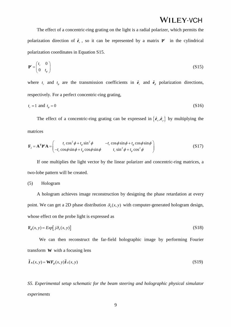
The effect of a concentric-ring grating on the light is a radial polarizer, which permits the
polarization direction of ˆre , so it can be represented by a matrix ′P in the cylindrical
polarization coordinates in Equation S15.
00rt
tφ
′ =
P (S15)
where rt and tφ are the transmission coefficients in ˆre and φe polarization directions,
respectively. For a perfect concentric-ring grating,
1rt = and 0tφ = (S16)
The effect of a concentric-ring grating can be expressed in { }ˆ ˆ,x ye e by multiplying the
matrices
2 2
2 2 2
cos sin cos sin cos sincos sin cos sin sin cos
r r
r r
t t t tt t t t
φ φ
φ φ
φ φ φ φ φ φφ φ φ φ φ φ
+ − +′= = − + +
TF A P A (S17)
If one multiplies the light vector by the linear polarizer and concentric-ring matrices, a
two-lobe pattern will be created.
(5) Hologram
A hologram achieves image reconstruction by designing the phase retardation at every
point. We can get a 2D phase distribution ( , )h x yϑ with computer-generated hologram design,
whose effect on the probe light is expressed as
[ ]( , ) ( , )hx y Exp j x yϑ=dF (S18)
We can then reconstruct the far-field holographic image by performing Fourier
transform W with a focusing lens
0( , ) ( , ) ( , )x y x y x y= WA dI F I (S19)
S5. Experimental setup schematic for the beam steering and holographic physical simulator
experiments

10
The same experimental setup was used for the beam steering and holographic physical
simulator experiments and is illustrated in Figure S6. Note that some reflective mirrors are
omitted for clarity of the diagram, and the distance between optical components is not shown
to the scale.
3-axis stage
CO2 Laser
Power sensor
RM
LP
PR
L1 L2
MCIris
Figure S6. Detailed diagram of the setup used in the beam steering and holographic physical
simulator experiments. RM, reflective mirror; LP, commercial linear polarizer; PR, 90° phase
retarder; L, focusing lens; MC, metacanvas.
S6. Experimental setup schematics for transition observation
The experimental setups used for characterizations of the metacanvas programmed as a linear
polarizer or a concentric-ring grating, as well as the transition observation with two
metacanvases simultaneously, are illustrated in Figure S7. Note that some reflective mirrors
are omitted for clarity, and the distance between optical components is not drawn to the scale.
The light immediately after the phase retarder is circularly polarized.

11
CO2 Laser
Power sensor
RM
LP1
PR
L1 L2 L3
LP2MC1
CO2 Laser
Power sensor
RM
LP1
PR
L1 L2 L3
LP2 MC2 Iris
3-axis stage
CO2 Laser
RM
LP1
PR
L1 L2 L3
MC1 MC2
b
c
a
Power sensor
Iris
3-axis stage
Figure S7. Detailed diagrams of a) the metacanvas as a linear polarizer, b) the metacanvas as
a concentric-ring grating, and c) the transition observation setups. RM, reflective mirror; LP,
commercial linear polarizer; PR, 90° phase retarder; L, focusing lens; MC, metacanvas.
S7. Temperature-dependent polarization ratio of the metacanvas as a linear polarizer
Figure 2c in the main text clearly shows a temperature-dependent polarization ratio of the
metacanvas programmed as a linear polarizer. This is because, when the global temperature of
12
the metacanvas was decreased, the written M-phase patterns on it went through a metal-
insulator phase transition and gradually faded away. After that, the metacanvas became a
homogenous I-phase VO2 film.
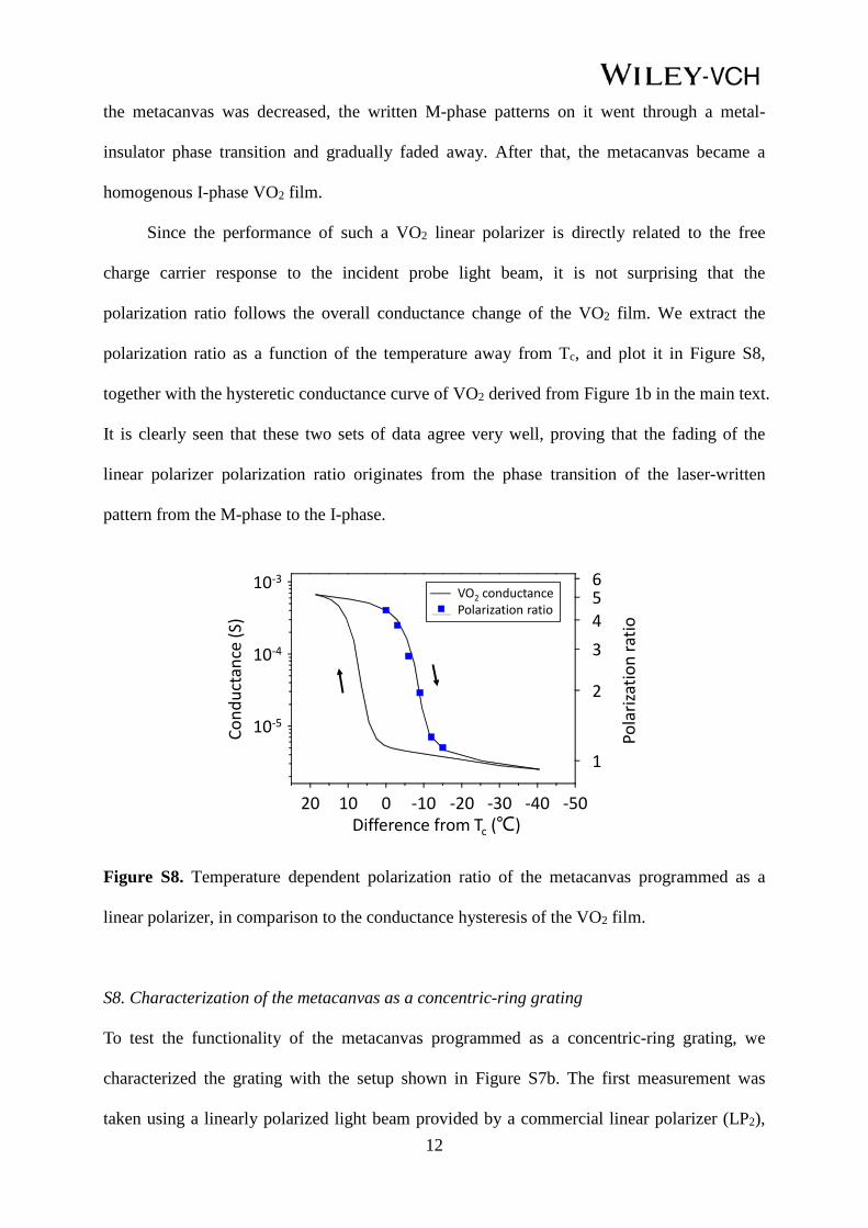
Since the performance of such a VO2 linear polarizer is directly related to the free
charge carrier response to the incident probe light beam, it is not surprising that the
polarization ratio follows the overall conductance change of the VO2 film. We extract the
polarization ratio as a function of the temperature away from Tc, and plot it in Figure S8,
together with the hysteretic conductance curve of VO2 derived from Figure 1b in the main text.
It is clearly seen that these two sets of data agree very well, proving that the fading of the
linear polarizer polarization ratio originates from the phase transition of the laser-written
pattern from the M-phase to the I-phase.
6
10-5
10-4
20 10 0 -10 -20 -30 -40
VO2 conductance Polarization ratio
Cond
ucta
nce
(S)
Difference from Tc (℃)-50
1
2
345
Pola
rizat
ion
ratio
10-3
Figure S8. Temperature dependent polarization ratio of the metacanvas programmed as a
linear polarizer, in comparison to the conductance hysteresis of the VO2 film.
S8. Characterization of the metacanvas as a concentric-ring grating
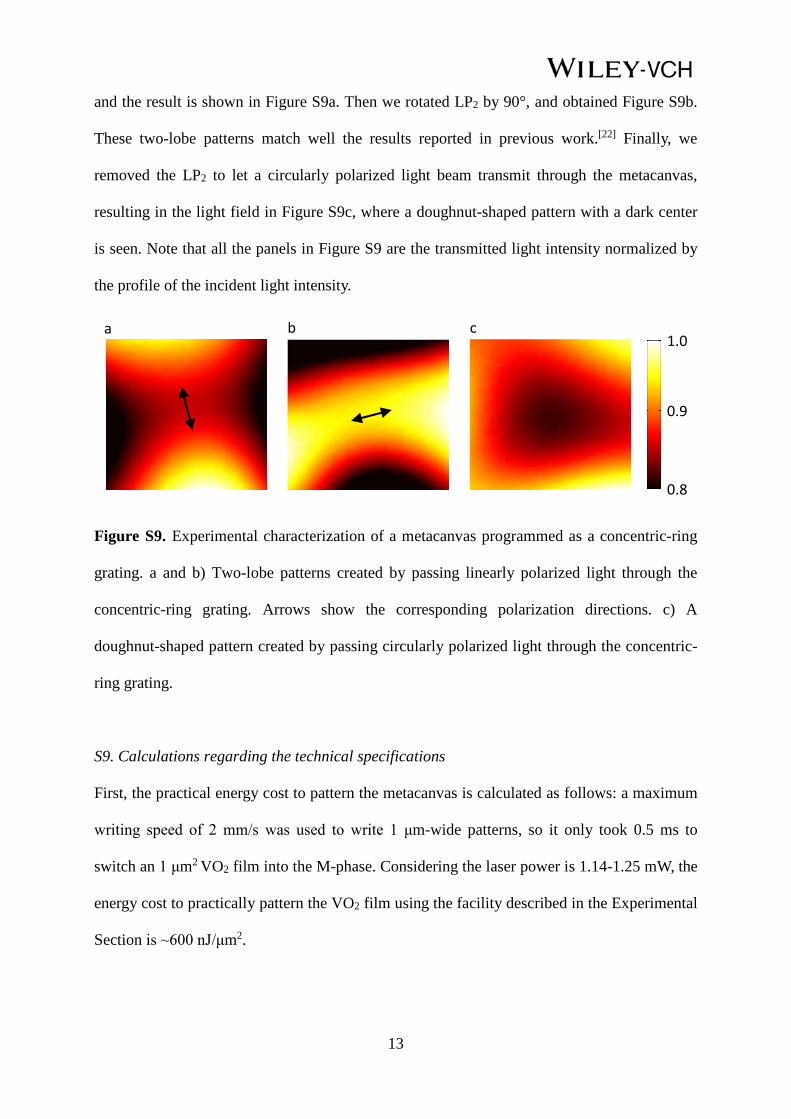
To test the functionality of the metacanvas programmed as a concentric-ring grating, we
characterized the grating with the setup shown in Figure S7b. The first measurement was
taken using a linearly polarized light beam provided by a commercial linear polarizer (LP2),
13
and the result is shown in Figure S9a. Then we rotated LP2 by 90°, and obtained Figure S9b.
These two-lobe patterns match well the results reported in previous work.[22] Finally, we
removed the LP2 to let a circularly polarized light beam transmit through the metacanvas,
resulting in the light field in Figure S9c, where a doughnut-shaped pattern with a dark center
is seen. Note that all the panels in Figure S9 are the transmitted light intensity normalized by
the profile of the incident light intensity.
a b c1.0
0.9
0.8
Figure S9. Experimental characterization of a metacanvas programmed as a concentric-ring
grating. a and b) Two-lobe patterns created by passing linearly polarized light through the
concentric-ring grating. Arrows show the corresponding polarization directions. c) A
doughnut-shaped pattern created by passing circularly polarized light through the concentric-
ring grating.
S9. Calculations regarding the technical specifications
First, the practical energy cost to pattern the metacanvas is calculated as follows: a maximum
writing speed of 2 mm/s was used to write 1 μm-wide patterns, so it only took 0.5 ms to
switch an 1 μm2 VO2 film into the M-phase. Considering the laser power is 1.14-1.25 mW, the
energy cost to practically pattern the VO2 film using the facility described in the Experimental
Section is ~600 nJ/μm2.

14
Secondly, the lower bound of the writing power needed is the latent heat of the phase
transition of the VO2 film plus the energy needed to heat it from the standby state to the M-
phase.[23] The theoretical energy TE needed to pattern VO2 is
TE V c T VHρ= ∆ + (S20)
where V is the unit volume of VO2 with a thickness of 200 nm and an area of 1 μm2, which is
calculated to be 2×10-13 cm3. ρ , c , H are the density (4.66 g/cm3), the specific heat (690
J/(kg·K)), and the latent heat of phase transition (250 J/cm3) of VO2, respectively.[23] Judging
from Figure 1b in the main text, the temperature change T∆ is 22 oC (heated from 68 oC to 90
oC). As such, TE is estimated to be 0.064 nJ/μm2.
Thirdly, the theoretical lower bound of the standby power is estimated by heat
dissipation from the sample surface to air as the only heat loss. Considering a sample size of
1.28×1.28 mm2 (the case of the hologram), the temperature difference of 48 oC (68 oC - 20
oC), and the heat transfer coefficient of 5 W/(m2·K) for convective air cooling, the ideal
standby power is estimated to be ~786 μW, which is much lower than the power consumption
of most electronic chips. In addition, all semiconductor chips generate heat and many of them
naturally reach ~70 oC while working. If there is such a chip nearby, no additional power is
needed to maintain the working temperature of the metacanvas. Also, only 2 at.% W doping is
known to decrease the phase transition temperature of VO2 from 68 oC to room temperature.
With proper W doping, an optimal working temperature for the metacanvas can be chosen to
achieve negligible standby power.
Finally, numerical simulation was conducted to calculate the upper bound of the erasing
time. For clarification, a Si chip (1×1×0.5 mm3) was used to imitate the metacanvas and air
cooling was set to be the only heat loss. The initial temperature of the Si chip and the
environment temperature were set to be 68 oC and 20 oC, respectively, and the heat transfer
coefficient was 5 W/(m2·K). The calculated maximum temperature within the Si chip as a

15
function of time is depicted in Figure S10, which indicates that ~27 s is needed to cool the
chip down to 45 oC (see Figure 1b in the main text) to erase all patterns.
40
Tem
pera
ture
(o C)
50
60
70
Time (s)0 10 20 30
Figure S10. Maximum temperature within the Si chip as a function of air cooling time.
Reference
[1] D. Y. Lei, K. Appavoo, F. Ligmajer, Y. Sonnefraud, R. F. Haglund Jr, S. A. Maier, ACS
Photonics 2015, 2, 1306.
[2] Z. Nie, E. Kumacheva, Nat. Mater. 2008, 7, 277.
[3] J. Fujita, Y. Ohnishi, Y. Ochiai, S. Matsui, Appl. Phys. Lett. 1996, 68, 1297.
[4] K. Appavoo, D. Y. Lei, Y. Sonnefraud, B. Wang, S. T. Pantelides, S. A. Maier, R. F.
Haglund Jr, Nano Lett. 2012, 12, 780.
[5] M. He, J. Hou, X. Wang, J. Zhang, Z. Yuan, L. Xiao, Y. Wei, S. Fan, K. Jiang, K.
Liu, Nano Lett. 2017, 17, 421.
[6] J. Rensberg, S. Zhang, Y. Zhou, A. S. McLeod, C. Schwarz, M. Goldflam, M. Liu, J.
Kerbusch, R. Nawrodt, S. Ramanathan, D. N. Basov, F. Capasso, C. Ronning, M. A.
Kats, Nano Lett. 2016, 16, 1050.
[7] R. M. Briggs, I. M. Pryce, H. A. Atwater, Opt. Express 2010, 18, 11192.
[8] R. Lopez, L. C. Feldman, R. F. Haglund Jr, Phys. Rev. Lett. 2004, 93, 177403.

16
[9] D. W. Ferrara, J. Nag, E. R. MacQuarrie, A. B. Kaye, R. F. Haglund Jr, Nano Lett. 2013,
13, 4169.
[10] J. Y. Suh, E. U. Donev, D. W. Ferrara, K. A. Tetz, L. C. Feldman, R. F. Haglund Jr, J.
Opt. A: Pure Appl. Opt. 2008, 10, 055202.
[11] C. McGahana, K. Appavoo, R. F. Haglund Jr, J. Vac. Sci. Technol., B 2013, 31, 06FE01.
[12] S. K. Earl, T. D. James, T. J. Davis, J. C. McCallum, R. E. Marvel, R. F. Haglund Jr, A.
Roberts, Opt. Express 2013, 21, 27503.
[13] M. Seo, J. Kyoung, H. Park, S. Koo, H. Kim, H. Bernien, B. J. Kim, J. H. Choe, Y. H.
Ahn, H.-T. Kim, N. Park, Q.-H. Park, K. Ahn, D. Kim, Nano Lett. 2010, 10, 2064.
[14] D. J. Shelton, K. R. Coffey, G. D. Boreman, Opt. Express 2010, 18, 1330.
[15] O. L. Muskens, L. Bergamini, Y. Wang, J. M. Gaskell, N. Zabala, C. de Groot, D. W.
Sheel, J. Aizpurua, Light Sci. Appl. 2016, 5, e16173.
[16] T. V. Son, C. O. F. Ba, R. Vallée, A. Haché, Appl. Phys. Lett. 2014, 105, 231120.
[17] Y.-W. Huang, H. W. H. Lee, R. Sokhoyan, R. A. Pala, K. Thyagarajan, S. Han, D. P. Tsai,
H. A. Atwater, Nano Lett. 2016, 16, 5319.
[18] M. M. Qazilbash, M. Brehm, G. O. Andreev, A. Frenzel, P. Ho, B. Chae, B. Kim, S. J.
Yun, H. Kim, A. V. Balatsky, O. G. Shpyrko, M. B. Maple, F. Keilmann, D. N. Basov,
Phys. Rev. B. 2009, 79, 075107.
[19] L. Huang, X. Chen, H. Mühlenbernd, H. Zhang, S. Chen, B. Bai, Q. Tan, G. Jin, K.
Cheah, C. Qiu, J. Li, T. Zentgraf, S. Zhang, Nat. Commun. 2013, 4, 2808.
[20] L. Huang, X. Chen, H. Mühlenbernd, G. Li, B. Bai, Q. Tan, G. Jin, T. Zentgraf, S. Zhang,
Nano Lett. 2012, 12, 5750.
[21] S. Larouche, Y.-J. Tsai, T. Tyler, N. M. Jokerst, D. R. Smith, Nat. Mater. 2012, 11, 450.
[22] W. Chen, W. Han, D. C. Abeysinghe, R. L. Nelson, Q. Zhan, J. Opt. 2010, 13, 015003.
[23] K. Wang, C. Cheng, E. Cardona, J. Guan, K. Liu, J. Wu, ACS Nano 2013, 7, 2266.