Embed Size (px)
Citation preview

3
A Low-Cost Van de Graaff Accelerator
by
Brian Andrew Winey
Submitted to the Department of Physics
in partial fulfillment of the requirements for the degree of
Bachelor of Science
at
Houghton College
May 2002
………………..……………………………………………………………………...
Brian Winey
Department of Physics
May 8 2002
……………………………………………………………………………………….
Dr. Mark Yuly
Associate Professor of Physics
Research Supervisor
………..……………………………………………………………………………...
Dr. Ronald Rohe
Associate Professor of Physics

4
A Low-Cost Van de Graaff Accelerator
by
Brian Andrew Winey
Submitted to the Department of Physics
on 8 May 2002 in partial fulfillment of the
requirements for the degree of
Bachelor of Science
Abstract
A small, low-cost Van de Graaff electrostatic accelerator capable of accelerating electrons and
producing bremsstrahlung x-rays has been constructed using components commonly found in
most undergraduate physics laboratories. The electrons originate within the negative high-
voltage terminal and are accelerated by a uniform electric field through an evacuated glass tube.
Electron currents of up to 6 A were collected in a Faraday cup. The end-point of the
bremsstrahlung x-ray energy spectrum has been measured to be between 300 and 400 keV.
Thesis Supervisor: Dr. Mark Yuly
Title: Assoc. Professor of Physics

5
CONTENTS
INTRODUCTION ....................................................................................................................................................... 7
1.1 A LOW-COST VAN DE GRAAFF ACCELERATOR .................................................................................................... 7 1.2 HISTORY ............................................................................................................................................................... 7
PRINCIPLE OF VAN DE GRAAFF OPERATION .............................................................................................. 10
ACCELERATOR DESIGN CONSIDERATIONS ................................................................................................. 14
3.1 APPARATUS ........................................................................................................................................................ 14 3.1.1 Principles of Our Van de Graaff Generator ............................................................................................... 15 3.1.2 Electron Gun and Faraday Cup ................................................................................................................. 16
3.2 OPERATION OF THE APPARATUS ......................................................................................................................... 17
CONCLUSION .......................................................................................................................................................... 29
APPENDIX A ............................................................................................................................................................. 30
THE VACUUM SYSTEM ............................................................................................................................................. 30 DIRECTIONS FOR OPERATION ................................................................................................................................... 31
REFERENCES .......................................................................................................................................................... 32

6
Table of Figures
Figure 1:A Simplified Drawing of a Van de Graaff Generator………………………………... 5
Figure 2: MIT 4 MV V.D.G Accelerator………………………………………….…………… 6
Figure 3: Sketch of an Early Accelerator Design…………………..………………………….. 12
Figure 4: Electron Gun Biasing Circuit………………………………………………………... 14
Figure 5: Scale Drawing of Faraday Cup and Cathode………………………………………... 14
Figure 6: 4000 V Test Circuit………………………………………………………………….. 15
Figure 7: Scale Drawing of the Apparatus……………………………………………………... 16
Figure 8: Photograph of the Apparatus………………………………………………………... 17
Figure 9: Simplified Drawing of the Apparatus………………………….……………………. 18
Figure 10: X-Ray Spectroscopy Circuit…………………………………..…………………… 18
Figure 11: Scintillator Placement….…………………………………………………………... 19
Figure 12: X-Ray Energy Spectra……………………………………………………………… 20
Figure 13: Bremsstrahlung Energy Distribution at 25………………………..………………. 21
Figure 14: Bremsstrahlung Energy Distribution at 43…………….……………….…………. 22
Figure 15: Bremsstrahlung Energy Distribution at 66…..……………………………………. 23
Figure 16: Bremsstrahlung Energy Distribution at 111..……………………………………... 24
Figure 17: Energy Spectrum Near the Bremsstrahlung Endpoint………………………..……. 25
Figure 18: Angular Distribution of Bremsstrahlung X-Rays………………………………….. 25
Figure 19: Proposed Acceleration Tube…………………………….…………………………. 27
Figure 20: Vacuum System………..…………………………………………………………... 28
Figure 21: Rotary Pump Drawing……………………………………………………………… 28

7
Introduction
1.1 A Low-Cost Van de Graaff Accelerator
The goal of this project was to design and construct a low-cost electrostatic accelerator,
capable of producing electron or ion beams for scattering experiments. Using a Van de Graaff
generator as a voltage source, the apparatus would be able to produce a stable electron or ion
beam in the range of 400 keV. If heavy hydrogen is substituted for the electrons and use is made
of the d-d neutron production reaction, the accelerator would be capable of producing neutrons
of about 3 MeV [1].
To use this reaction, the deuterium gas would be ionized, then the deuterons would be
accelerated to energies of the range of 150 keV to 450 keV. At the end of the chamber would be
a target of copper. At first, the deuterons
would impregnate the copper target. Then, as
the density of deuterons in the target
increased, accelerated deuterons would
interact with those in the copper to produce
either 3He and a neutron or
3H (Tritium) and a
proton. If the beam is operated between the
energies of 150 and 450 keV, the probability
of producing a neutron is much greater than
that of a proton [2].
1.2 History
In 1929 R. J. Van de Graaff constructed his
first model of a belt-charged electrostatic
generator at Princeton University [3]. The idea
of a belt-charged electrostatic generator can be
traced to earlier dates [4], but it was Van de
Graaff who built the first functional model.
The original device consisted of two 24-inch
diameter charged terminals, one positive, the
+
-
| | | | | | | | | | | | | | |
Upper Comb
Bottom Comb
Charged Belt
Pulley
Sphere
-
-
-
- -
-
- -
-
- -
-
Figure 1: A simplified drawing of a Van de
Graaff Generator. The important components are
the two pulleys, the two combs, the charged belt,
and the sphere.
Pulley
- -
V

8
other negative, and could produce a potential of 1.5 MV [5]. Three years later, the Massachusetts
Institute of Technology (MIT) funded the construction of a Van de Graaff generator consisting of
two 15-foot diameter spheres that could reach a potential of 5.1 MV [6]. The early models
contained only two pulleys, two combs, a charged belt, and a charged sphere (Fig. 1).
These Van de Graaff generators were designed to be ion sources. The large MIT
generator used one of the support columns to contain an evacuated acceleration tube, which
could be used to accelerate electrons or positive ions to 2.75 MeV [7]. In 1937, researchers
concluded that using a pressurized environment to control humidity and increase air pressure
would increase the corona breakdown voltage (see Fig. 2) [8]. This allowed for smaller
accelerators and increased operating voltages. Some studies concluded that pressure and
maximum potential are linearly
related; i.e. if the pressure of the air is
doubled, the maximum potential of the
sphere doubles [9].
Concentric potential surfaces
surrounding the high voltage terminal
were added to decrease the voltage
difference between the sphere and the
innermost shell (Fig. 2). Instead of the
full potential between the sphere and
ground, the concentric surfaces have
voltage differences that divide the
total potential of the sphere; i.e. if the
terminal has a potential of 4 MeV and
is surrounded by three evenly spaced
concentric shells, the voltage drop
between the sphere and the innermost
shell, between shells one and two, two
and three, and three and ground will be
one MeV. Developments have continued
during the past sixty years. Pressurized air
Figure 2: A drawing of the MIT 4 MV design with a
pressurized container, equipotential rings, and
equipotential sufaces. Two acceleration tubes are
shown within the column, one for positive ions, the
other for negative. (taken from [10])

9
has been replaced by nitrogen, freon, and sulfur hexaflouride, the last having the highest
breakdown voltage [11], but little has changed with the general design.
Van de Graaff accelerators are used in a variety of ways. Nuclear experiments often
require low energy (less than ten MeV) ions. Astrophysics experiments that investigate stellar
nuclear reactions require low energy collisions. The low energy beams for these investigations
can be efficiently supplied by Van de Graaff accelerators. Van de Graaff accelerators can
produce nearly monoenergetic (all particles having the same energy) beams. The voltage of the
terminal can be finely adjusted to the specific voltages needed for an experiment. The voltage
can be regulated by a grounded probe that can be placed at various distances from the outer
concentric surface. The maximum potential difference between the probe and the concentric
surface is a function of the distance between the two and will determine the voltage of the
terminal. Van de Graaff generators are also very reliable, having few moving parts that could
break or malfunction.

10
Principle of Van de Graaff Operation
The original Van de Graaff design has changed little since R. J. Van de Graaff first
published his idea in 1931 [12], which uses the principle that inside a conducting sphere, the
electric field is zero. Therefore, if there is a supply of charges to the inside of the sphere, they
will repel to the surface of the conducting sphere. The only limit to the charge on the sphere is
the breakdown voltage of the surrounding medium. If the sphere was totally isolated in an
infinite vacuum, the total charge capacity of the sphere would be infinity.
An obvious problem is how to supply a conducting sphere with charged particles from
the inside. As a solution, Van de Graaff suggested the use of an insulating charged belt that runs
between two pulleys (see Fig. 1). Once an insulator receives charges, they are not free to move
around on the surface. Therefore, as the charges approach the conducting sphere, they can not
migrate down the belt, repelled by the electric field. Instead, they continue to the inside of the
sphere. If a conductor was used, the electric potential at the base of the Van de Graaff would
always need to be greater than that of the conducting sphere in order to force the charged
particles into the sphere.
But how can charges be “attached” to the insulating belt? Van de Graaff proposed the
following method. Ground the bottom pulley and place a charged metal screen near the moving
belt. Raise the potential of the screen until the electrons on the screen move to the pulley,
because of the corona effect. As electrons move to the lower potential pulley, they will pass onto
the moving belt, becoming embedded in the insulator. Van de Graaff proposed a similar process
within the high voltage terminal, requiring that the top pulley be neutral and the charges be
repelled from the insulating material onto a metal screen near the belt. The charges would be
repelled by the pulley but encounter no field due to the charges on the sphere. Hence, they would
migrate to the surface of the sphere.
Van de Graaff generators require an insulating column, which contains the insulating belt
that supplies charge to the sphere, and are surrounded by air or a pressurized gas that serves as an
insulator. Good insulating media will have a high breakdown voltage (the potential when the
medium begins to conduct allowing charge to escape from the sphere). The Corona effect
happens when the ionization potential of the air is reached on a charged surface and the electrons

11
can migrate through the gaseous mixture of ionized air molecules to ground [13]. This surface
discharge will limit the maximum voltage and charge for a given radius sphere.
Spheres are used because charges on a smooth surface spread out as much as possible,
until the electrical forces are in equilibrium. A sphere is continuous surface, having no edges or
points. If the surface is uneven, charges will concentrate on a sharp edge, creating a larger
electric field. This stronger field will cause the surface to obtain the breakdown field sooner at
some points on the surface, resulting in a discharge with a lower total charge on the sphere.
Since the sphere is surrounded by an insulator, it acts as a capacitor, for which
Q = CV (1)
where V is the voltage across the capacitor plates and Q is the charge on the plates. The
capacitance, C, for a sphere is
rC o4 (2)
where r is the radius of the sphere. Taking the derivative of Eq. 1 we get
dt
dVC
dt
dQ (3)
and,
dt
dVCi (4)
For our Van de Graaff generator, the up current is constant, while the current down the
equipotential rings and support column is proportional to V. Therefore,
dt
dVC
R
Vii u (5)
where iu is the up current from the belt, R is the resistance of the high voltage terminal, and R
V
is the current that is lost to the corona effect and down the equipotential rings and support
column. When the Van de Graaff generator is first turned on (t = 0), the potential is zero and dt
dV
(the rate the potential of the sphere is changing) is large. After a period of time, uiR
V and
0dt
dV, which means that the voltage remains constant.

12
Reorganizing Eq. 5 we get the differential equation:
C
i
RC
V
dt
dV u (6)
Eq. 6 provides the time dependent voltage equation for a Van de Graaff generator:
)1( RCt
u eRiV
(7)
Now, since the breakdown field of air is approximately 30,000V/cm [14] we find that the
maximum attainable voltage on a spherical high voltage terminal is given by
r
V
r
kQEsphere
2 because
r
kQV ,
where sphereE is the electric field of a sphere, Q is the charge on the sphere, r is distance from the
center of the sphere to a point outside of the sphere (in this case r is the radius of the sphere
because we want to find the voltage on the surface of the sphere), and V is the voltage of the
sphere.Therefore, given the maximum electric field of a sphere surrounded by air,
rcm
VrEV sphere 30000 (8)
Our Van de Graaff generator has a radius of 13 cm and, using Eq. 8, a maximum attainable
voltage of 410,000V and a maximum charge on the sphere of 5.92C.
The original design was altered to accommodate an acceleration chamber in the same
glass cylinder surrounding the charged belt. Therefore, if a cathode is attached to the end of the
acceleration chamber in the sphere and a grounded anode is located at the other end the electrons
will be accelerated toward the anode.
If the electric field in the acceleration tube is not uniform electrons may be deflected.
Equipotential rings were added to provide a constant electric field. Equipotential rings are placed
at equal distances along the acceleration tube. If the acceleration tube is in the Van de Graaff
support column, then the column is surrounded with the rings (see Fig. 2). Since the rings are
placed at equal distances apart, there is equal resistance between each ring. The resistance in this
case causes an equal voltage drop between each ring because of the “corona discharge which
equalizes potential gradient” [15] . The equal voltage drops create a constant electric field,
accelerating the electrons along the axis of the tube.
The electrons, after being accelerated down the evacuated tube, strike the anode or target
being held at ground. When electrons strike the target, they decelerate, releasing energy in the

13
form of bremsstrahlung x-rays energy. The endpoint of the bremsstrahlung spectrum can be
measured at 0 to find the energy of the electrons.

14
Accelerator Design Considerations
3.1 Apparatus
The idea for the apparatus came from Frank B. Lee’s article, “A Homemade Atom
Smasher.” [16] This article describes a Van de Graaff generator in contact with a spherical high
voltage terminal. The high voltage terminal is attached to one end of an evacuated tube that is
surrounded by equipotential rings of wire and a cathode is located at the other end of the tube.
The voltage generator produces a
positive potential, which attracts
electrons from the cathode. The
target is enclosed in the high
voltage terminal (see Fig. 3).
In our apparatus the
cathode was placed in the high
voltage terminal and the Van de
Graaff produced a negative
potential. Copper wire was used
for equipotential rings, a cathode
from a cathode ray tube was the
source of electrons, and a
Faraday Cup, held at ground, was
used to “collect” the accelerated
electrons. A drawing of our
apparatus can be found in Fig. 7
and a scale drawing is provided
in Fig. 9. The vacuum pump used
to evacuate the chamber is
discussed in Appendix A.
The changes made in the design allowed the beam spot on the target to be observed, since
the target Faraday cup is at ground potential. The current was measured by attaching an ammeter
Figure 3: A sketch of Frank B. Lee’s accelerator design. The
VDG would provide the high voltage. Inside the high voltage
terminal would be the target and ammeter. The filament would
be at the base of the acceleration tube. (taken from [17])

15
between the target and ground instead of placing the ammeter inside the terminal. The
bremsstrahlung x-ray energy was measured to find the energy of the electrons.
3.1.1 Principles of Our Van de Graaff Generator
The Van de Graaff generator used in this experiment used no external voltage source to
supply current to the sphere. Instead, it used a principle called “Continuously Charging
Electrophorous” in which the chemical properties of two substances result in a charge build up.
In this case, the molecules of the insulating belt have a positive ionization number and the
molecules of the pulley have a negative ionization number. When they come into contact, they
form “superficial” covalent bonds, chemical bonds only on the surface where electrons are
shared. Electrons migrate from the pulley to the belt, creating a positively charged pulley. When
the belt separates from the pulley, most of the electrons return to the pulley [18]. The result is a
positively charged pulley. After a short time the pulley builds up a substantial charge. The
bottom comb then becomes negatively charged due to the positive potential of the pulley. Once
the potential difference between the comb and the pulley becomes large enough, the air between
the two breaks down and electrons migrate toward the pulley and stick to belt that is traveling
through the space between the comb and pulley. Therefore, no external voltage source is needed
to supply charge to the insulating belt. A similar process is used at the top, except the pulley is a
neutral substance. Electrons repel from the pulley, off of the belt and to the surface of the sphere.
The maximum voltage of our 13 cm radius Van de Graaff generator was calculated to be
approximately 410 kV, using the phenomenological estimate of Eq. 8 [19]. Because of several
factors, the actual voltage of the generator was probably closer to 50% of the maximum [20].
The potential of the Van de Graaff generator when it was in contact with the high voltage
terminal of the accelerator may have been higher because the surface area was basically doubled,
allowing more charge to be stored. The capacitance of the Van de Graaff high voltage terminal,
using Eq. 2, was approximately 14.5 pF, and, using Eq. 1, the charge on the sphere was
approximately 5.92 C.
The charge supplied to the sphere, Ic, was measured to be around 8 A. Tests of the
apparatus revealed a beam current in the range of 4-6 A. This suggests that the charge supplied
to the sphere leaves the sphere in ways other than the beam. The “missing charges” are lost to the
corona effect and migration down the support column.

16
3.1.2 Electron Gun and Faraday Cup
The electron gun has a filament, a cathode, and an acceleration grid (see Fig. 4). The
filament heats the cathode, which is coated with a substance that releases electrons when it is
heated. The acceleration grid is at a small positive potential relative to the cathode and
accelerates the electrons away from the cathode, toward the acceleration tube. A six-volt battery
supplied the voltage difference between the acceleration gird and the cathode, as well as the
power needed to heat the filament. A battery was
used because it is a floating voltage source and
could therefore be placed inside the high voltage
terminal. The whole cathode floated at the high
voltage so the electrons produced by the electron
gun were at the negative potential of the sphere. A
schematic of the cathode biasing used can be seen
in Fig. 4, with feed-through pin numbers and
dimensions shown in Fig. 5.
Scale 1:4
Figure 5: The dimensions of the Faraday cup, used to collect the
accelerated electrons, and the cathode, the electron gun. The feed-
through pin numbers correspond to those given in Fig. 4.
Figure 4: A schematic of the electron gun
(filament, cathode, accelerating grid) and
the battery that provided the biasing.
Cathode
+ 6V –
Battery
Accelerating Grid
Filament
High Voltage
Pin 5 Pin 1 Pin 6
Radi us 1.6 cm
3.8 cm
Faraday Cup Di mensions
1.3 cm1.9 cm
Cathode Dimensi ons
Pin 6
Pin 5
Pin 1
3.2 cm
FrontBack
Side
Radi us 0.65 cm
17
The Faraday cup, which was placed at the other end of evacuated tube, was an aluminum
cylinder filled with a material that glowed when struck by electrons. This was used so the
electron beam could be monitored visually. The Faraday cup was connected to ground, through
an ammeter to measure the beam current. The dimensions of the Faraday cup are shown in Fig 5.
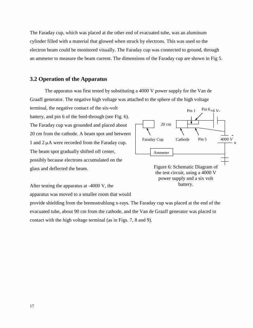
3.2 Operation of the Apparatus
The apparatus was first tested by substituting a 4000 V power supply for the Van de
Graaff generator. The negative high voltage was attached to the sphere of the high voltage
terminal, the negative contact of the six-volt
battery, and pin 6 of the feed-through (see Fig. 6).
The Faraday cup was grounded and placed about
20 cm from the cathode. A beam spot and between
1 and 2 A were recorded from the Faraday cup.
The beam spot gradually shifted off center,
possibly because electrons accumulated on the
glass and deflected the beam.
After testing the apparatus at -4000 V, the
apparatus was moved to a smaller room that would
provide shielding from the bremsstrahlung x-rays. The Faraday cup was placed at the end of the
evacuated tube, about 90 cm from the cathode, and the Van de Graaff generator was placed in
contact with the high voltage terminal (as in Figs. 7, 8 and 9).
4000 V
+6 V-
Faraday Cup Cathode
Pin 1
Pin 5
Pin 6
20 cm
Figure 6: Schematic Diagram of
the test circuit, using a 4000 V
power supply and a six volt
battery.
Ammeter
-
+

18
Figure 7: A scale drawing of the apparatus. The Van de
Graaff terminal provided the high voltage. The cathode
inside the high voltage terminal was the electron source.
The equipotential rings provided a constant electric field
in the evacuated tube and the Faraday cup collected the
accelerated electrons.
BAT
Radius = 13 cm110.7 cm
High Voltage
Terminal
12.2 cm
14.5 cm
19.5 cm 5 cm
99.4 cm
15.6 cm
Acceleration Tube
To Vacuum Pump
Faraday Cup
Equipotential Rings
Cathode
Ion Vacuum Gauge
Van de Graaff
Terminal
Scale 1:8.5
Radius = 13 cm

19
Figure 8: A picture of the apparatus with the Van de Graaff generator in the
background, the high voltage terminal, the evacuated tube with copper
equipotential rings, the Faraday cup and the plastic scintillator.
20
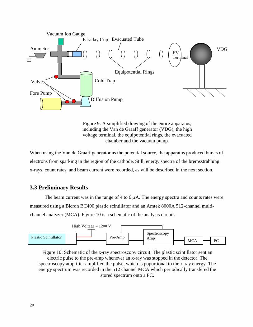
When using the Van de Graaff generator as the potential source, the apparatus produced bursts of
electrons from sparking in the region of the cathode. Still, energy spectra of the bremsstrahlung
x-rays, count rates, and beam current were recorded, as will be described in the next section.
3.3 Preliminary Results
The beam current was in the range of 4 to 6 A. The energy spectra and counts rates were
measured using a Bicron BC400 plastic scintillator and an Amtek 8000A 512-channel multi-
channel analyzer (MCA). Figure 10 is a schematic of the analysis circuit.
Plastic Scintillator
High Voltage 1200 V
Pre-Amp Spectroscopy
Amp MCA PC
Figure 10: Schematic of the x-ray spectroscopy circuit. The plastic scintillator sent an
electric pulse to the pre-amp whenever an x-ray was stopped in the detector. The
spectroscopy amplifier amplified the pulse, which is poportional to the x-ray energy. The
energy spectrum was recorded in the 512 channel MCA which periodically transfered the
stored spectrum onto a PC.
Figure 9: A simplified drawing of the entire apparatus,
including the Van de Graaff generator (VDG), the high
voltage terminal, the equipotential rings, the evacuated
chamber and the vacuum pump.
VDG
G
Faraday Cup
Ammeter
Vacuum Ion Gauge
Valves
Fore Pump
Diffusion Pump
Cold Trap
Evacuated Tube
Equipotential Rings
HV
Terminal

21
The course gain on the spectroscopy amplifier was set to 5.8. The high voltage power supply was
set to 1200 V and the recording time was 100 seconds. The energy spectrum was calibrated using
137 Cs and
133 Ba, which emit gamma rays at 662 keV and 356 keV respectively. Background was
measured for 100 seconds with the Van de Graaff generator turned off. Measurements of
bremsstrahlung x-rays were taken at varying angles from the beam line, at 25, 43, 66, 86 and
111. Fig. 11 shows the positioning of the plastic scintillator. Figures 12-17 show the energy
spectra and count rates as a function of angle.
Figure 11: Detector placement for angular measurements
Theta () is the angle from the beam line. The plastic
scintillator was placed at various angles and energy spectra
and count rates were measured.
Incident Electron
Beam

22
Figure 12: Energy spectra at 25 (thick), 43 (dark thick ), 66 (top dashed), 86 (bottom
dashed), 111 (dotted) and background (solid) for 100 seconds collection period, displaying the
relative intensities of the bremsstrahlung x-rays at each position. The 25 and 43 energy spectra
overlap.
0
100000
200000
300000
400000
500000
600000
700000
0 500
Co
un
ts
X-Ray Energy (keV)

23
Figure 13: Energy distribution at 25. The background is the dotted line. Error bars are smaller
than the symbols.
0
20000
40000
60000
80000
100000
120000
140000
160000
250 270 290 310 330 350 370 390 410 430
Co
un
ts
X-Ray Energy (keV)

24
Figure 14: Energy distribution at 43. The background is the dotted line. Error bars are smaller
than the symbols.
0
20000
40000
60000
80000
100000
120000
140000
160000
250 270 290 310 330 350 370 390 410 430
Co
un
ts
X-Ray Energy (keV)
25
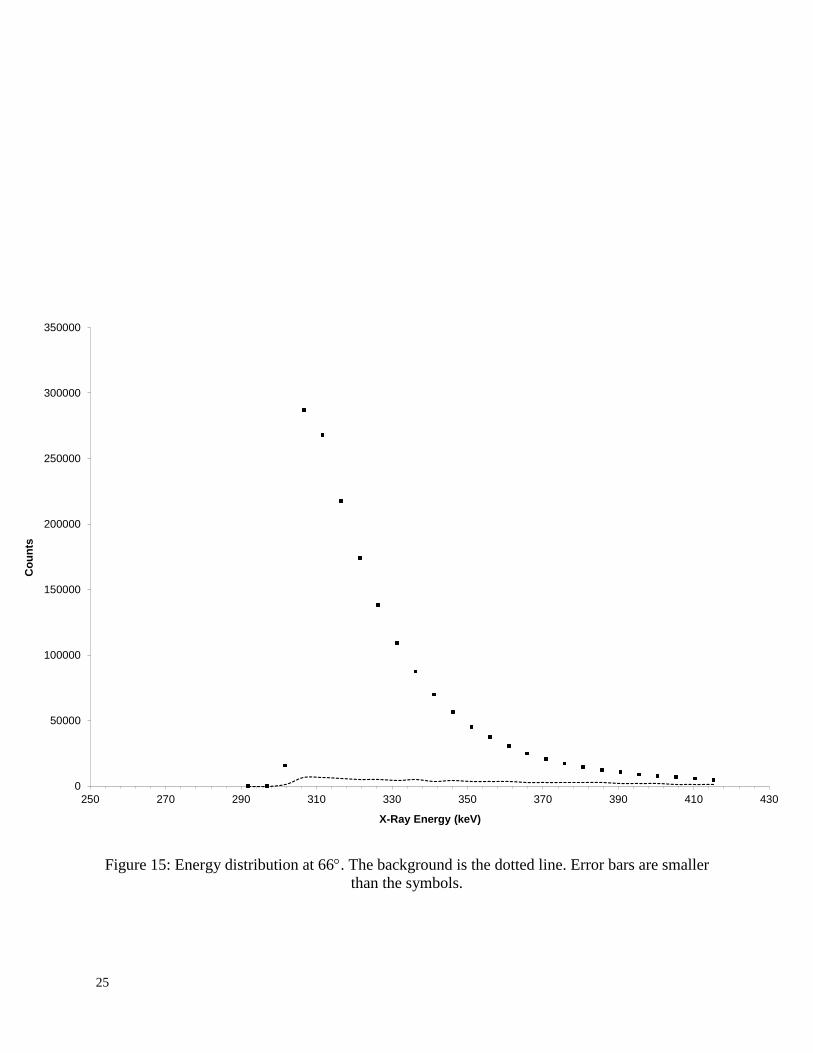
Figure 15: Energy distribution at 66. The background is the dotted line. Error bars are smaller
than the symbols.
0
50000
100000
150000
200000
250000
300000
350000
250 270 290 310 330 350 370 390 410 430
Co
un
ts
X-Ray Energy (keV)

26
Figure 16: Energy distribution at 111. The background is the dotted line. Error bars are smaller
than the symbols.
0
100000
200000
300000
400000
500000
600000
250 300 350 400 450 500
Co
un
ts
Energy (keV)

27
Figure 17: Energy spectrum near the bremsstrahlung
endpoint energy for 25. The background is the dotted
line. Error bars are smaller than the symbols.
Figure 18: Angle distribution of bremsstrahlung x-rays.
The counts at lower angles would be expected to be
greater than counts at high angles. The counts were lower
at the low angles because of the attenuation of the
bremsstrahlung x-rays in the Faraday cup and other
materials of the apparatus.
0
5000
10000
15000
20000
25000
30000
35000
40000
45000
320 340 360 380 400 420
Co
un
ts
X-Ray Energy (keV)
0
1
2
3
4
5
6
7
8
9
10
0 20 40 60 80 100 120
Co
un
ts (
x106
)
Angle off Beam Line (degs)

28
Fig. 17 shows the region of greatest interest, the region of the bremsstrahlung x-ray energy
endpoint. As can be seen from this plot of energy versus counts, the spectrum lacks an easily
defined endpoint because the sparking created a non-monoenergetic beam of electrons. The
energy spectra of the bremsstrahlung x-rays appear to merge with the background x-rays near
400 keV. During the experiment, the amplifier gain was too low, causing the area near the
endpoint to fall into a few bins at the low energy end of the spectrum. In future measurements,
the gain on the spectroscopy amplifier should be raised to at least 20x to increase the number of
channels devoted to the region of interest, 300-400 keV.

29
Conclusion
The next step for this project is the construction of an aluminum/plastic ring acceleration
chamber, replacing the glass tube (see Fig. 20). The aluminum and plastic rings are currently
being milled. The rings will be glued together with vacuum epoxy, and plastic dowels will be
used to ensure the rings are aligned. The advantage of using aluminum and plastic rings is that
any charge that “sticks” to the chamber walls will not create a disturbance in the electric field.
Instead, the charge will be transferred to the outside of the ring and will join with the other
charges that are descending the voltage ladder of the equipotential aluminum rings. Also, the
sparking that occurred in the region of the cathode needs to be corrected. Possible remedies
include moving the cathode farther into the high voltage terminal to a region with smaller fields
and removing sharp edges from the terminal and cathode.
Figure 19:
A drawing of the accelerator chamber constructed of
alternating aluminum and plastic rings connected to the
high voltage terminal.
Drawn by: Willi Suckau 1/12/2000
Figure 19: A sketch of the proposed accelerator tube
constructed of alternating aluminum and plastic rings
connected to the high voltage terminal. (taken from [21])

30
Appendix A
The Vacuum System
Charged particle acceleration requires a long mean free path, since charged particles
interacting with the air lose energy by ionizing the atoms in the air. Also, a filament will burn out
if it is not in a low pressure environment. In
order to reduce the pressure and increase the
mean free path, the apparatus employed a
three stage vacuum pump system: a cold trap,
a diffusion pump and a rotary fore pump.
(See Fig. 21).
First, the apparatus was pumped
down to a pressure of 10-4
Torr with
the fore pump. The fore pump is a
mechanical (rotary) vacuum pump. It
operates with an off-center piston and
moveable vane. The vane maintains a seal between the piston and the chamber edge to ensure
that no air can pass between them. As the piston rotates, it creates an increasing size cavity on
the right side where the intake from the vacuum chamber is located. This creates a low pressure
region into which air molecules flow from the higher pressure in the vacuum chamber. The
piston continues to rotate and the vane seals this pocket of air molecules. As the piston rotates, it
confines the air to a smaller volume on the exhaust side of the chamber. As the piston
compresses the air molecules in the cavity, it
forces a valve open on the exhaust and the
air exits the chamber (see Fig 22).
Next, the cold trap is filled with
liquid nitrogen. The cold trap is made of two
cylinders, the inner holds liquid nitrogen and
the outer one is connected to the vacuum
chamber. The inner cylinder becomes so cold that it lowers the thermal energy of the air
1
3 2
Figure 20: A drawing of the vacuum pump apparatus. First,
the fore pump was used to reduce the pressure to 10-4
Torr.
Then, the diffusion pump was turned on and the cold trap was
filled with liquid nitrogen.
Rotation
From Vacuum
Chamber Exhaust
Vane
Figure 21:
A rotary pump with an off-center piston

31
molecules in the outer cylinder. As the molecules cool, they sink to the bottom of the cold trap
where they are removed by the diffusion pump.
The diffusion pump creates jets of oil that are directed downwards by nozzles. The high
velocity oil vapor creates a downward current in which air molecules become trapped, flowing
down to exhaust to the fore pump, where the air molecules are removed. The oil condenses
against the cool walls of the diffusion pump chamber (the walls are cooled by a fan and cooling
fins) and sinks back to the oil resevoir at the bottom of the pump. Any oil that rises near the cold
trap condenses against cooler baffles, and then returns to the resevoir [22]. A diffusion pump
must not be operated until the pressure is below 10-3
Torr or the oil will oxidize and become
useless for the diffusion pumping process [23].
Directions for Operation
To turn on the vacuum pump:
1) Make sure valves 1 and 3 are open and 2 is closed. (valve 2 is a pressure release that
allows air into the chamber).
2) Turn on the Fore Pump.
3) Wait until the pressure is at least of the order of 10-4
Torr.
4) Fill the cold trap with liquid nitrogen.
5) Turn on the Diffusion Pump, using 75 Volts.
6) Continue to check and fill the cold trap as needed.
To shut down the vacuum pump:
1) Turn off the diffusion pump.
2) Close valve 1.
3) Open Valve 2
4) Turn off the fore pump
5) Close valves 2 and 3.

32
References
[1] J.E. Brolley and J.L. Fowler. Monoenergetic Neutron Sources, Reactions with Light Nuclei.
(Interscience Publishers, Inc., New York, 1960), p: 77.
[2] Ibid, p: 76.
[3] M. Stanley Livingston and John P. Blewett. Particle Accelerators. (McGraw-Hill Book
Company, New York, 1962), p. 31.
[4] Ibid.
[5] Ibid.
[6] Ibid. p. 32.
[7] Ibid. p. 32.
[8] Ibid. p. 47.
[9] Ibid.
[10] Ibid. p. 51.
[11] Ibid. p. 48.
[12] R.J. Van de Graaff. Physical Review. 38:1919A (1931).
[13] M. Stanley Livingston and John P. Blewett. Particle Accelerators. (McGraw-Hill Book
Company, New York, 1962), p. 39.
[14] Richard E. Berg. “Van de Graaff Generators: Theory, Maintenance, and Belt Fabrication.”
The Physics Teacher. May 1990, 283.
[15] Frank B. Lee. “A Homemade Atom Smasher.” The Scientific American Book of Products
for The Amateur Scientist. (Simon and Shuster, New York, 1960), p. 347.
[16] Ibid.
[17] Ibid.
[18] Beaty, William J. “Van de Graaff Generator, Belt, and Roller Explaination.”
http://www.eskimo.com/~billb/emotor/belt.html. May 3, 2002.
[19] Richard E. Berg. “Van de Graaff Generators: Theory, Maintenance, and Belt Fabrication.”
The Physics Teacher. May 1990, 283.
[20] Ibid.
[21] Willi Suckau, Eastern Nazarene College, experiment logbook, Dec. 12, 2000.
[22] W. Bryant, P. Treado, and J. Lambert. Accelerator Nulear Physics. (High Voltage
Engineering Company, Burlington, 1970), p. 13.
[23] Melissinos, Adrian C. Experiments in Modern Physic. (Academic Press Inc., New York,
1966), p. 131.


![Anatomy [Van Graaff]](https://img.pdfslide.net/doc/110x75/55cf9885550346d033981e8a/anatomy-van-graaff.jpg)