Embed Size (px)
Citation preview
A Lower Carbon Foot Print Process for Electrolytic Production of Metals from Oxides Dissolved in Molten Salts
Uday B. PAL1,2 1. Div. of Materials Science and Engineering, Boston University, 15 Saint Mary’s St., Brookline, MA 02446, USA
2. Dept. of Mechanical Engineering, Boston University, 110 Cummington St., Boston, MA 02215, USA
Abstract: There is a societal impetus towards lowering the carbon footprint to counteract the negative effects of climate
change. This paper will outline the potential of the solid oxide membrane (SOM) process to produce energy-intensive
metals like magnesium, titanium, and rare earths directly from their oxides dissolved in non-consumable molten salts, by
electrolysis, at lower cost and with lower carbon foot print compared to the current processes. In one configuration of the
SOM process, the metal is produced at the cathode and oxygen gas evolves at the anode. The anode is encased within a one-
end-closed solid-oxygen-ion conducting yttria-stabilized-zirconia (YSZ) tube. The paper will discuss the procedure for the
selection of the molten salt for dissolving the metal oxide and the operating parameters for the process. Important
parameters that influence the selection process are melting point, solubility of the oxide, volatility, membrane stability, and
metal solubility. Based on the flux selected, the operating parameters such as temperature, applied potential, current density,
and design of electrode placement are determined.
Introduction
In this paper, we will first describe the SOM process as it applies to the energy-efficient and environmentally-sound production of magnesium from magnesium oxide. We will next describe the challenges encountered while using this process for the production of transition metals like titanium and rare earths like ytterbium from their respective oxides. Finally we will propose a novel magnesiothermic SOM process that can enable production of transition metals from their oxides.
Magnesium Production
Currently, about 42% of all US magnesium metal production is used as alloying addition to aluminum. Magnesium addition increases hardness and corrosion resistance. Other primary uses include the desulphurization of steel, production of ductile cast iron, metallothermic reduction of other more expensive metals, and as a possible medium for hydrogen storage. The primary impediment to the more widespread use of magnesium in many other applications (particularly in the auto industry, where weight is a concern) is its high cost. [1]
Currently, the production of magnesium is energy and materials intensive and creates environmental pollutants. Conventional production routes for magnesium metal include metallothermic reduction and direct electrolysis of magnesium chloride. Thermal reduction of calcined dolomite or magnesite at reduced pressure and temperatures in the range of 1200°C - 1400°C is used in the metallothermic process. This process creates large amounts of slag byproduct (4-5 tons of slag per ton of magnesium). The electrolytic process generates potentially harmful chlorine gas as a byproduct that must be disposed of properly. The cost of disposal drives up the price of magnesium created using this process. In addition, the electrolytic process usually utilizes an anhydrous chloride feed material that is produced by an elaborate and expensive brine dehydration process. The feed preparation process can account for 30% of the capital cost as well as about 80% of the plant footprint. [2]; use of hydrous chloride feed increases the carbon anode consumption and decreases efficiency.
The SOM Process
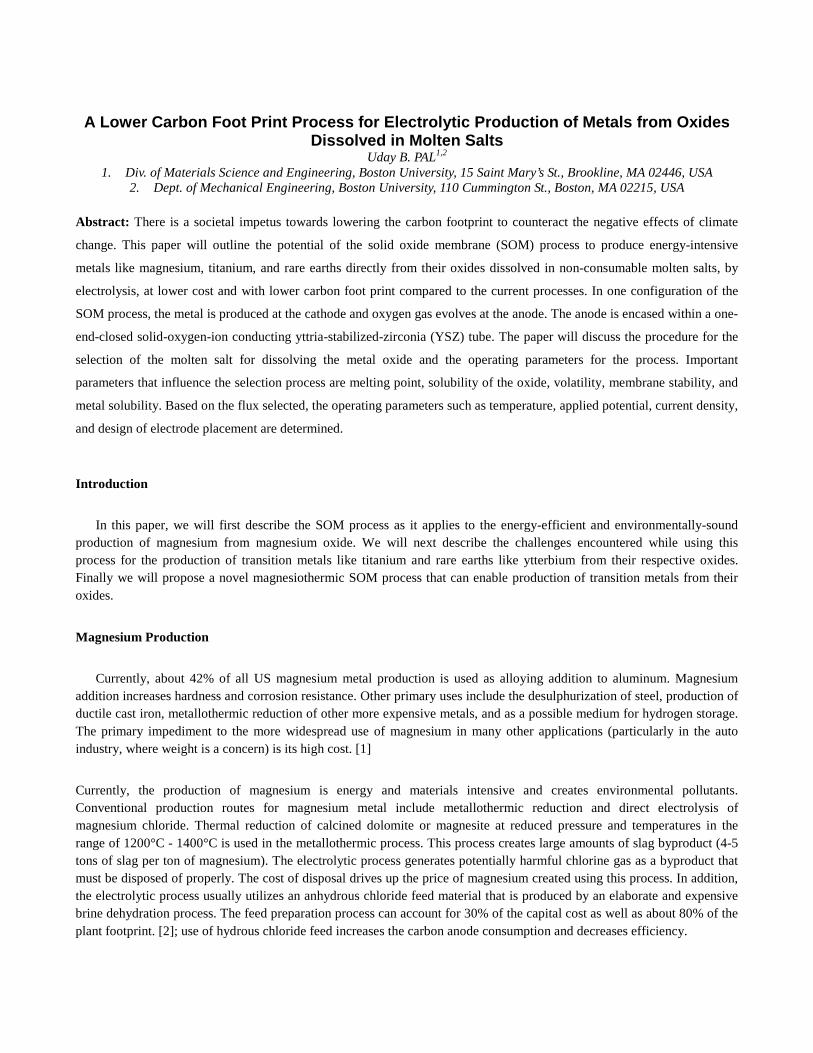
It has been demonstrated in the laboratory that high-energy-content metals can be electrolytically produced from their respective oxides dissolved in fluoride-based molten fluxes, between 1100 and 13000C. The process employs an oxygen-ion-conducting yttria-stabilized zirconia (YSZ) solid electrolyte that separates an inert solid metallic cathode in the flux and an oxygen producing anode. In the case of magnesium, the cathode can be stainless steel, and the oxygen producing anode can be A-site and/or B-site doped p-type perovskite such as LaMnO3 or liquid silver. To obtain maximum environmental benefit, one would employ renewable energy for producing the electrical energy required for SOM electrolysis. If fossil-based source is used to obtain the required electrical energy, then the carbon foot print can be lowered by using liquid metal anodes and directly feeding C or other hydrocarbon-based reductant into the liquid metal anode to substitute for part of the needed electrical energy. In other words, this process allows the use of chemical energy and thus decreases the overall need for the fossil-fuel derived electrical energy. Since the carbon foot print associated with fossil-fuel derived electrical energy is much larger than the carbon foot print of equivalent energy obtained chemically, the SOM process will have a lower carbon footprint even if fossil-fuel derived electrical energy is used. These variations of the SOM process have been tried in the laboratory with liquid copper, tin, and silver anodes [3-8]. The schematic of different versions of the SOM process are shown in Figure 1. The YSZ electrolyte separates the inert cathode and the flux from the liquid metal anode. The flux has high ionic conductivity (4 S/cm), high magnesium oxide solubility (> 10 w%), and low viscosity (< 1 poise). When the applied electrical potential between the electrodes exceeds the dissociation potential of the oxide, oxygen ions are pumped out of the flux through the YSZ membrane and are oxidized at YSZ/liquid metal anode interface. When the liquid metal anode is silver the oxygen evolves as oxygen gas and when the liquid metal anode is copper or tin, the oxygen enters the anode as dissolved oxygen [O]Anode and is subsequently oxidized by the carbon or hydrogen that is used as a reactant feed to the supply part of the energy and also prevent oxidation of the liquid tin or copper anode. All three liquid metal anodes used (copper, tin and silver) have low vapor pressure, high oxygen solubility and high oxygen diffusivity in the temperature range of interest. [9-12]
Figure 1. Schematic of the SOM process for the metals production
The SOM operating temperature is between 1100 and 13000C, so the magnesium reduced at the cathode, is in the gas phase. It is condensed in a separate chamber yielding high-purity Mg metal.
The anodic and cathodic reactions along with the transport of various species are shown in Figure 1. The rate of the slowest step determines the overall metal production rate. In order to increase the overall rate, the rate of the slowest step needs to be enhanced. The ionic flux is an electron blocker and the total ionic resistance of the flux is comparable to that of the YSZ membrane. Adequate stirring of the flux and having sufficient MgO in the flux are essential to ensure that transport in the flux is rapid. The temperature is sufficiently high (≥1000oC) so charge transfer reactions are rapid. Since the oxygen solubility and diffusivity are high in the liquid anode and the anode is well stirred by the product gases, the oxygen transport in the liquid anode is rapid. The analysis indicates that the process is likely controlled by the ionic resistance of the system. The current efficiency and the operating voltage of an electrolytic process govern the specific energy expenditure (kWh/kg) of the process. For the specific case of magnesium, the energy expenditure of the process can be calculated as:
N =U
0.454η=
V ⋅Amp ⋅hrgram
=kWhkg
1
Where:
N is specific energy expenditure, U is cell potential and η is current efficiency.
The overall cell potential of a SOM type electrolytic cell can be calculated as the sum of the individual potential drops in the system. Neglecting polarization loses due to mass transfer and charge transfer, the operating cell potential of the SOM process can be calculated as:
U = Eo +
1 ⋅ jκ el
+2 ⋅ jκYSZ
+ iR
2
Where:
U is the cell potential in volts,
Eo is the dissociation potential of the species being reduced,
L1 and l2 are the current path lengths through the electrolyte and YSZ respectively,
J is the current density, κel and κYSZ are the conductivities of the electrolyte and YSZ, respectively, and iR is the Ohmic losses within the cathode, anode, contacts, and leads.
Experimental Results
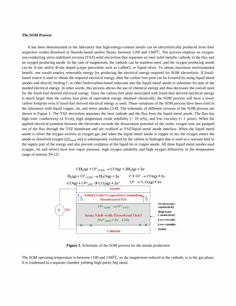
An electrolytic cell and Mg collection apparatus were designed to produce and contain 100 g of magnesium. The electrolytic cell shown in Figure 2a utilizes 33 cm2 of the liquid anode area and can operate at anodic current densities as high as 1 A/cm2. The YSZ solid electrolyte was in the form of a one-end-closed tube that contained the liquid anode. High-density graphite rod was used as a consumable supplemental carbon feed in the liquid copper and tin. Experiments were
also conducted employing liquid silver as anodes and without using any supplemental carbon feed. The steel crucible that held the MgO containing ionic flux served as the cathode. In order to protect the YSZ tube above the flux from the Mg vapor that is produced along the wall of the stainless steel container (cathode), argon gas is introduced into the chamber as a carrier gas and diluent. The argon-magnesium gas mixture passes out of the electrolysis chamber to the lower condensation chamber where the Mg(g) is condensed. The cell was electrochemically characterized using impedance spectroscopy and electrical potential sweeps. A power supply was used to apply a constant potential to the cell for electrolysis. The applied electrical potential and resulting current from the cell were logged at 1 second intervals using a data logger. The electrolysis experiments were performed with continuous MgO feed between 1100 and 1300oC at an applied electric potential of 3-4 V and current density of 1A/cm2. Mg was collected in the condenser and the energy consumption of the process according to equation 1 was 9-10 KWh/kg. This energy consumption is lower then the current state-of-the-art chloride electrolysis process which also includes energy required for pre-processing the chloride. Spectroscopic analysis of the Mg deposit showed a purity of 99.99% (Figure 2b).
(a) (b)
Figure 2. (a) Schematic of the Mg SOM reactor; (b) Mg deposit and its spectroscopic analysis
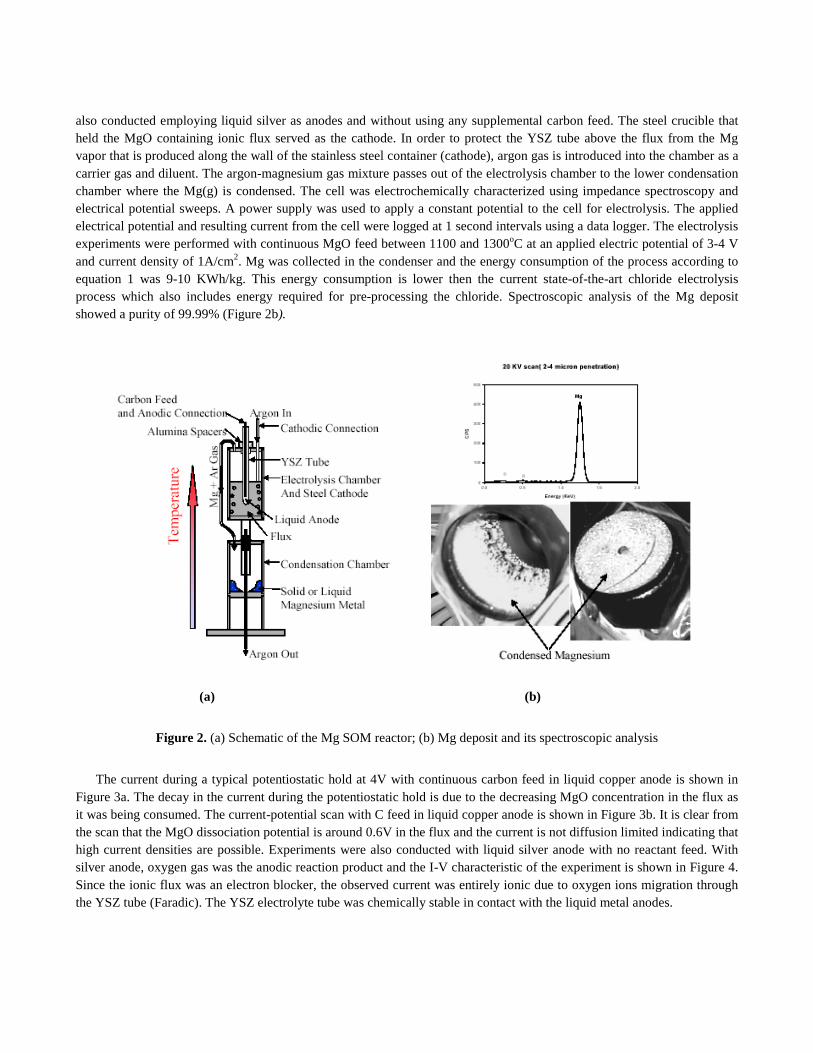
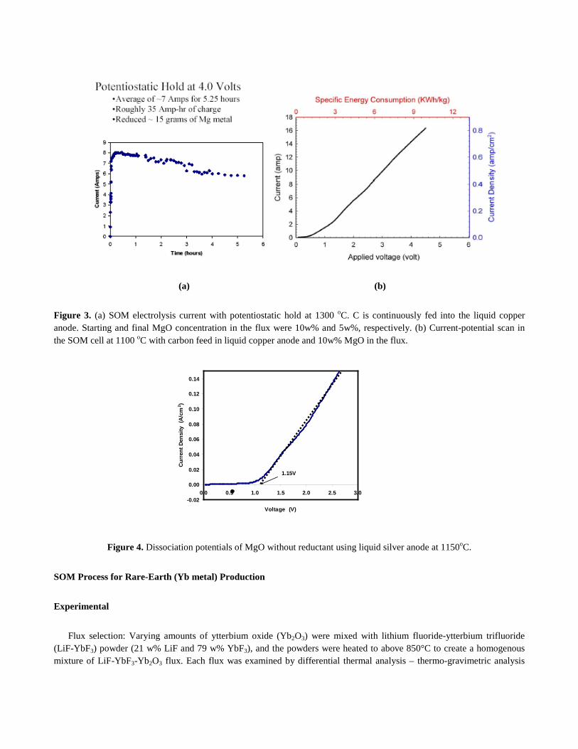
The current during a typical potentiostatic hold at 4V with continuous carbon feed in liquid copper anode is shown in Figure 3a. The decay in the current during the potentiostatic hold is due to the decreasing MgO concentration in the flux as it was being consumed. The current-potential scan with C feed in liquid copper anode is shown in Figure 3b. It is clear from the scan that the MgO dissociation potential is around 0.6V in the flux and the current is not diffusion limited indicating that high current densities are possible. Experiments were also conducted with liquid silver anode with no reactant feed. With silver anode, oxygen gas was the anodic reaction product and the I-V characteristic of the experiment is shown in Figure 4. Since the ionic flux was an electron blocker, the observed current was entirely ionic due to oxygen ions migration through the YSZ tube (Faradic). The YSZ electrolyte tube was chemically stable in contact with the liquid metal anodes.
(a) (b)
Figure 3. (a) SOM electrolysis current with potentiostatic hold at 1300 oC. C is continuously fed into the liquid copper anode. Starting and final MgO concentration in the flux were 10w% and 5w%, respectively. (b) Current-potential scan in the SOM cell at 1100 oC with carbon feed in liquid copper anode and 10w% MgO in the flux.
Figure 4. Dissociation potentials of MgO without reductant using liquid silver anode at 1150oC.
SOM Process for Rare-Earth (Yb metal) Production
Experimental
Flux selection: Varying amounts of ytterbium oxide (Yb2O3) were mixed with lithium fluoride-ytterbium trifluoride (LiF-YbF3) powder (21 w% LiF and 79 w% YbF3), and the powders were heated to above 850°C to create a homogenous mixture of LiF-YbF3-Yb2O3 flux. Each flux was examined by differential thermal analysis – thermo-gravimetric analysis
-0.02
0.00
0.02
0.04
0.06
0.08
0.10
0.12
0.14
0.0 0.5 1.0 1.5 2.0 2.5 3.0
Voltage (V)
Curr
ent D
ensi
ty (
A/cm
2 )
1.15V
(DTA-TGA), during which the temperature was gradually cycled above the melting point of Yb (819°C), to determine the solubility of Yb2O3 in the flux and the melting point of the flux.
Stability tests: In order to confirm that YSZ tube was compatible and stable in the LiF-YbF3-Yb2O3 flux during the SOM process, a stability test was completed in which an YSZ tube was submerged in the flux and heated to the SOM operating temperature for six hours– longer than the expected operating time for the preliminary SOM experiments. Interactions between Yb metal, flux and the stainless steel crucible were also heated together for six hours to ensure that a pure Yb product could be produced. These tests were performed in a very low oxygen partial pressure (pO2) environment by purging the setup with forming gas (5% H2–N2).
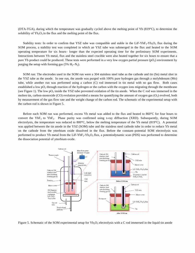
SOM run: The electrodes used in the SOM run were a 304 stainless steel tube as the cathode and tin (Sn) metal shot in the YSZ tube as the anode. In one run, the anode was purged with 100% pure hydrogen gas through a molybdenum (Mo) tube, while another run was performed using a carbon (C) rod immersed in tin metal with no gas flow. Both cases established a low pO2 through reaction of the hydrogen or the carbon with the oxygen ions migrating through the membrane (see Figure 1). The low pO2 inside the YSZ tube prevented oxidation of the tin anode. When the C rod was immersed in the molten tin, carbon-monoxide (CO) evolution provided a means for quantifying the amount of oxygen gas (O2) evolved, both by measurement of the gas flow rate and the weight change of the carbon rod. The schematic of the experimental setup with the carbon rod is shown in Figure 5.
Before each SOM run was performed, excess Yb metal was added to the flux and heated to 860°C for four hours to convert the YbF3 to YbF2. Phase purity was confirmed using x-ray diffraction (XRD). Subsequently, during SOM electrolysis, the temperature was reduced to 800°C, below the melting temperature of the Yb metal (819°C). A potential was applied between the tin anode in the YSZ (SOM) tube and the stainless steel cathode tube in order to reduce Yb metal on the cathode from the ytterbium oxide dissolved in the flux. Before the constant–potential SOM electrolysis was performed to produce Yb metal from the LiF-YbF2-Yb2O3 flux, a potentiodynamic scan (PDS) was performed to determine the dissociation potential of ytterbium oxide.
Figure 5. Schematic of the SOM experimental setup for Yb2O3 electrolysis with a C rod immersed in the liquid tin anode
Characterization after SOM run: After cooling, the YSZ tube was examined by optical microscopy. The flux and deposit were analyzed by XRD, energy-dispersive x-ray spectroscopy (EDS) and wavelength dispersive x-ray spectroscopy (WDS). The EDS was run on a JSM-6100 JEOL Scanning Electron Microscope with an ISIS Oxford Energy Dispersive X-Ray Spectrometer, XRD was performed on a Bruker D8 Focus, and the WDS analysis was done on a JXA-733 JEOL Microprobe.
Results and Discussion
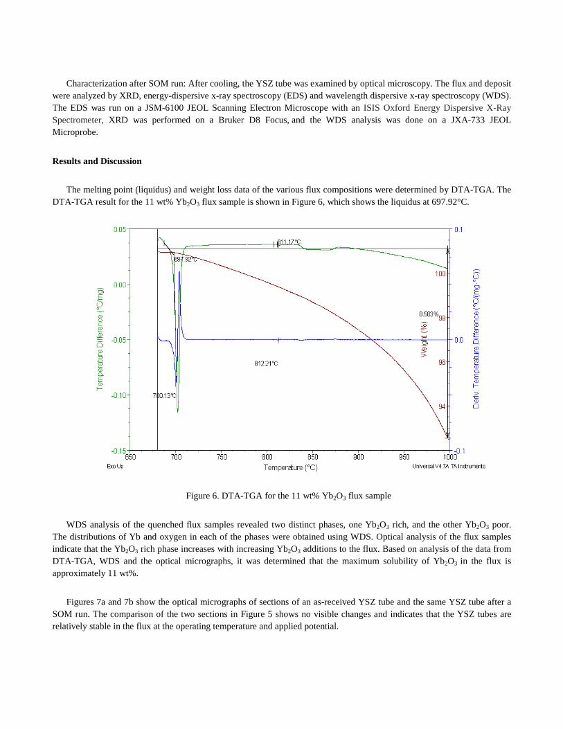
The melting point (liquidus) and weight loss data of the various flux compositions were determined by DTA-TGA. The DTA-TGA result for the 11 wt% Yb2O3 flux sample is shown in Figure 6, which shows the liquidus at 697.92°C.
Figure 6. DTA-TGA for the 11 wt% Yb2O3 flux sample
WDS analysis of the quenched flux samples revealed two distinct phases, one Yb2O3 rich, and the other Yb2O3 poor. The distributions of Yb and oxygen in each of the phases were obtained using WDS. Optical analysis of the flux samples indicate that the Yb2O3 rich phase increases with increasing Yb2O3 additions to the flux. Based on analysis of the data from DTA-TGA, WDS and the optical micrographs, it was determined that the maximum solubility of Yb2O3 in the flux is approximately 11 wt%.
Figures 7a and 7b show the optical micrographs of sections of an as-received YSZ tube and the same YSZ tube after a SOM run. The comparison of the two sections in Figure 5 shows no visible changes and indicates that the YSZ tubes are relatively stable in the flux at the operating temperature and applied potential.
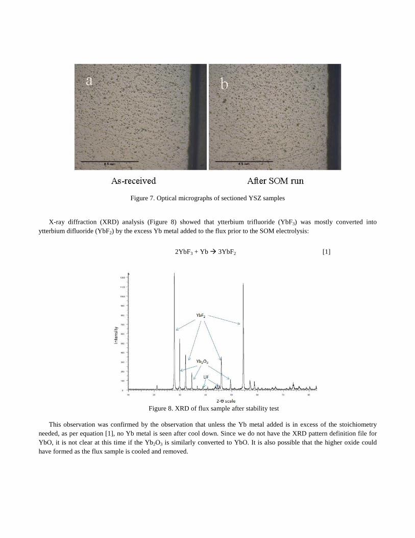
Figure 7. Optical micrographs of sectioned YSZ samples
X-ray diffraction (XRD) analysis (Figure 8) showed that ytterbium trifluoride (YbF3) was mostly converted into ytterbium difluoride (YbF2) by the excess Yb metal added to the flux prior to the SOM electrolysis:
2YbF3 + Yb 3YbF2 [1]
Figure 8. XRD of flux sample after stability test
This observation was confirmed by the observation that unless the Yb metal added is in excess of the stoichiometry needed, as per equation [1], no Yb metal is seen after cool down. Since we do not have the XRD pattern definition file for YbO, it is not clear at this time if the Yb2O3 is similarly converted to YbO. It is also possible that the higher oxide could have formed as the flux sample is cooled and removed.
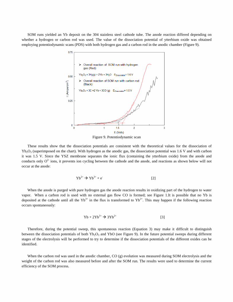
SOM runs yielded an Yb deposit on the 304 stainless steel cathode tube. The anode reaction differed depending on whether a hydrogen or carbon rod was used. The value of the dissociation potential of ytterbium oxide was obtained employing potentiodynamic scans (PDS) with both hydrogen gas and a carbon rod in the anodic chamber (Figure 9).
Figure 9. Potentiodynamic scan
These results show that the dissociation potentials are consistent with the theoretical values for the dissociation of Yb2O3 (superimposed on the chart). With hydrogen as the anodic gas, the dissociation potential was 1.6 V and with carbon it was 1.5 V. Since the YSZ membrane separates the ionic flux (containing the ytterbium oxide) from the anode and conducts only O2- ions, it prevents ion cycling between the cathode and the anode, and reactions as shown below will not occur at the anode:
Yb2+ Yb3+ + e- [2]
When the anode is purged with pure hydrogen gas the anode reaction results in oxidizing part of the hydrogen to water vapor. When a carbon rod is used with no external gas flow CO is formed; see Figure 1.It is possible that no Yb is deposited at the cathode until all the Yb3+ in the flux is transformed to Yb2+. This may happen if the following reaction occurs spontaneously:
Yb + 2Yb3+ 3Yb2+ [3]
Therefore, during the potential sweep, this spontaneous reaction (Equation 3) may make it difficult to distinguish between the dissociation potentials of both Yb2O3 and YbO (see Figure 9). In the future potential sweeps during different stages of the electrolysis will be performed to try to determine if the dissociation potentials of the different oxides can be identified.
When the carbon rod was used in the anodic chamber, CO (g) evolution was measured during SOM electrolysis and the weight of the carbon rod was also measured before and after the SOM run. The results were used to determine the current efficiency of the SOM process.
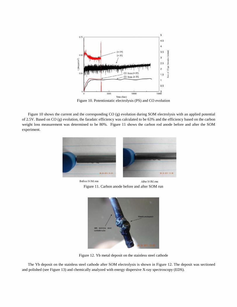
Figure 10. Potentiostatic electrolysis (PS) and CO evolution
Figure 10 shows the current and the corresponding CO (g) evolution during SOM electrolysis with an applied potential of 2.5V. Based on CO (g) evolution, the faradaic efficiency was calculated to be 63% and the efficiency based on the carbon weight loss measurement was determined to be 80%. Figure 11 shows the carbon rod anode before and after the SOM experiment.
Figure 11. Carbon anode before and after SOM run
Figure 12. Yb metal deposit on the stainless steel cathode
The Yb deposit on the stainless steel cathode after SOM electrolysis is shown in Figure 12. The deposit was sectioned and polished (see Figure 13) and chemically analyzed with energy dispersive X-ray spectroscopy (EDS).
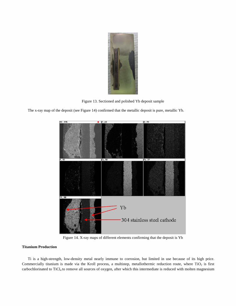
Figure 13. Sectioned and polished Yb deposit sample
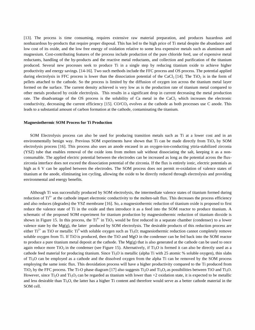
The x-ray map of the deposit (see Figure 14) confirmed that the metallic deposit is pure, metallic Yb.
Figure 14. X-ray maps of different elements confirming that the deposit is Yb
Titanium Production
Ti is a high-strength, low-density metal nearly immune to corrosion, but limited in use because of its high price. Commercially titanium is made via the Kroll process, a multistep, metallothermic reduction route, where TiO2 is first carbochlorinated to TiCl4 to remove all sources of oxygen, after which this intermediate is reduced with molten magnesium
[13]. The process is time consuming, requires extensive raw material preparation, and produces hazardous and nonhazardous by-products that require proper disposal. This has led to the high price of Ti metal despite the abundance and low cost of its oxide, and the low free energy of oxidation relative to some less expensive metals such as aluminum and magnesium. Cost-contributing features of the process include production of the pure chloride feed, use of expensive metal reductants, handling of the by-products and the reactive metal reductants, and collection and purification of the titanium produced. Several new processes seek to produce Ti in a single step by reducing titanium oxide to achieve higher productivity and energy savings. [14-16]. Two such methods include the FFC process and OS process. The potential applied during electrolysis in FFC process is lower than the dissociation potential of the CaCl2 [14]. The TiO2 is in the form of pellets attached to the cathode. So the process is limited by the diffusion of oxygen ion across the titanium metal layer formed on the surface. The current density achieved is very low as is the production rate of titanium metal compared to other metals produced by oxide electrolysis. This results in a significant drop in current decreasing the metal production rate. The disadvantage of the OS process is the solubility of Ca metal in the CaCl2 which increases the electronic conductivity, decreasing the current efficiency [15]. CO/CO2 evolves at the cathode as both processes use C anode. This leads to a substantial amount of carbon formation at the cathode, contaminating the titanium.
Magnesiothermic SOM Process for Ti Production
SOM Electrolysis process can also be used for producing transition metals such as Ti at a lower cost and in an environmentally benign way. Previous SOM experiments have shown that Ti can be made directly from TiO2 by SOM electrolysis process [16]. This process also uses an anode encased in an oxygen-ion-conducting yttria-stabilized zirconia (YSZ) tube that enables removal of the oxide ions from molten salt without dissociating the salt, keeping it as a non-consumable. The applied electric potential between the electrodes can be increased as long as the potential across the flux-zirconia interface does not exceed the dissociation potential of the zirconia. If the flux is entirely ionic, electric potentials as high as 6 V can be applied between the electrodes. The SOM process does not permit re-oxidation of valence states of titanium at the anode, eliminating ion cycling, allowing the oxide to be directly reduced through electrolysis and providing environmental and energy benefits.
Although Ti was successfully produced by SOM electrolysis, the intermediate valence states of titanium formed during reduction of Ti4+ at the cathode impart electronic conductivity to the molten-salt flux. This decreases the process efficiency and also reduces (degrades) the YSZ membrane [16]. So, a magnesiothermic reduction of titanium oxide is proposed to first reduce the valence state of Ti in the oxide and then introduce it as a feed into the SOM reactor to produce titanium. A schematic of the proposed SOM experiment for titanium production by magnesiothermic reduction of titanium dioxide is shown in Figure 15. In this process, the Ti4+ in TiO2 would be first reduced in a separate chamber (condenser) to a lower valence state by the Mg(g), the latter produced by SOM electrolysis. The desirable products of this reduction process are either Ti2+ as TiO or metallic Ti0 with soluble oxygen such as Ti3O; magnesiothermic reduction cannot completely remove soluble oxygen from Ti. If TiO is produced, then the TiO and MgO in the condenser can be fed back into the SOM reactor to produce a pure titanium metal deposit at the cathode. The Mg(g) that is also generated at the cathode can be used to once again reduce more TiO2 in the condenser (see Figure 15). Alternatively, if Ti3O is formed it can also be directly used as a cathode feed material for producing titanium. Since Ti3O is metallic (alpha Ti with 25 atomic % soluble oxygen), thin slabs of Ti3O can be employed as a cathode and the dissolved oxygen from the alpha Ti can be removed by the SOM process employing the same ionic flux. This deoxidation process will have a higher productivity compared to the Ti produced from TiO2 by the FFC process. The Ti-O phase diagram [17] also suggests Ti2O and Ti3O2 as possibilities between TiO and Ti3O. However, since Ti2O and Ti3O2 can be regarded as titanium with lower than +2 oxidation state, it is expected to be metallic and less desirable than Ti3O, the latter has a higher Ti content and therefore would serve as a better cathode material in the SOM cell.
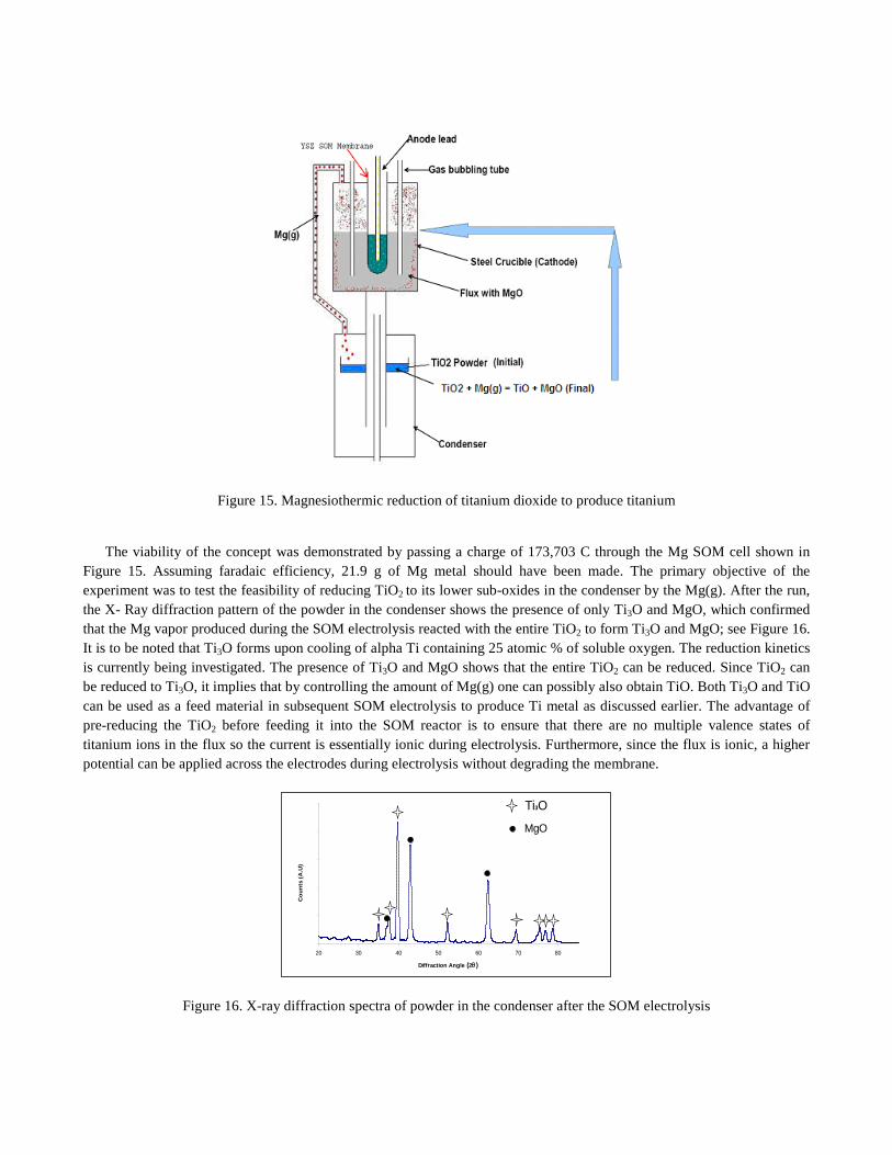
Figure 15. Magnesiothermic reduction of titanium dioxide to produce titanium
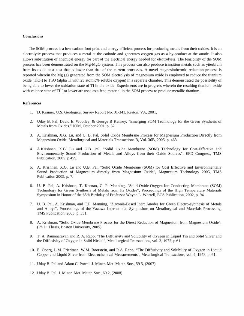
The viability of the concept was demonstrated by passing a charge of 173,703 C through the Mg SOM cell shown in Figure 15. Assuming faradaic efficiency, 21.9 g of Mg metal should have been made. The primary objective of the experiment was to test the feasibility of reducing TiO2 to its lower sub-oxides in the condenser by the Mg(g). After the run, the X- Ray diffraction pattern of the powder in the condenser shows the presence of only Ti3O and MgO, which confirmed that the Mg vapor produced during the SOM electrolysis reacted with the entire TiO2 to form Ti3O and MgO; see Figure 16. It is to be noted that Ti3O forms upon cooling of alpha Ti containing 25 atomic % of soluble oxygen. The reduction kinetics is currently being investigated. The presence of Ti3O and MgO shows that the entire TiO2 can be reduced. Since TiO2 can be reduced to Ti3O, it implies that by controlling the amount of Mg(g) one can possibly also obtain TiO. Both Ti3O and TiO can be used as a feed material in subsequent SOM electrolysis to produce Ti metal as discussed earlier. The advantage of pre-reducing the TiO2 before feeding it into the SOM reactor is to ensure that there are no multiple valence states of titanium ions in the flux so the current is essentially ionic during electrolysis. Furthermore, since the flux is ionic, a higher potential can be applied across the electrodes during electrolysis without degrading the membrane.
0
50
100
150
200
250
20 30 40 50 60 70 80
Diffraction Angle (2θ)
Cou
nts
(A.U
)
Ti3O
MgO
Figure 16. X-ray diffraction spectra of powder in the condenser after the SOM electrolysis
Conclusions
The SOM process is a low-carbon-foot-print and energy efficient process for producing metals from their oxides. It is an electrolytic process that produces a metal at the cathode and generates oxygen gas as a by-product at the anode. It also allows substitution of chemical energy for part of the electrical energy needed for electrolysis. The feasibility of the SOM process has been demonstrated on the Mg-MgO system. This process can also produce transition metals such as ytterbium from its oxide at a cost that is lower than that of the current processes. A novel magnesiothermic reduction process is reported wherein the Mg (g) generated from the SOM electrolysis of magnesium oxide is employed to reduce the titanium oxide (TiO2) to Ti3O (alpha Ti with 25 atomic% soluble oxygen) in a separate chamber. This demonstrated the possibility of being able to lower the oxidation state of Ti in the oxide. Experiments are in progress wherein the resulting titanium oxide with valence state of Ti2+ or lower are used as a feed material in the SOM process to produce metallic titanium.
References
1. D. Kramer, U.S. Geological Survey Report No. 01-341, Reston, VA, 2001.
2. Uday B. Pal, David E. Woolley, & George B Kenney, “Emerging SOM Technology for the Green Synthesis of Metals from Oxides.” JOM, October 2001, p. 32.
3. A. Krishnan, X.G. Lu, and U. B. Pal, Solid Oxide Membrane Process for Magnesium Production Directly from
Magnesium Oxide, Metallurgical and Materials Transactions B, Vol. 36B, 2005, p. 463.
4. A.Krishnan, X.G. Lu and U.B. Pal, "Solid Oxide Membrane (SOM) Technology for Cost-Effective and Environmentally Sound Production of Metals and Alloys from their Oxide Sources", EPD Congress, TMS Publication, 2005, p.455.
5. A. Krishnan, X.G. Lu and U.B. Pal, "Solid Oxide Membrane (SOM) for Cost Effective and Environmentally
Sound Production of Magnesium directly from Magnesium Oxide", Magnesium Technology 2005, TMS Publication 2005, p. 7.
6. U. B. Pal, A. Krishnan, T. Keenan, C. P. Manning, "Solid-Oxide-Oxygen-Ion-Conducting Membrane (SOM)
Technology for Green Synthesis of Metals from Its Oxides", Proceedings of the High Temperature Materials Symposium in Honor of the 65th Birthday of Professor Wayne L. Worrell, ECS Publication, 2002, p. 94.
7. U. B. Pal, A. Krishnan, and C.P. Manning, "Zirconia-Based Inert Anodes for Green Electro-synthesis of Metals
and Alloys", Proceedings of the Yazawa International Symposium on Metallurgical and Materials Processing, TMS Publication, 2003, p. 351.
8. A. Krishnan, “Solid Oxide Membrane Process for the Direct Reduction of Magnesium from Magnesium Oxide”,
(Ph.D. Thesis, Boston University, 2005).
9. T. A. Ramanarayan and R. A. Rapp, “The Diffusivity and Solubility of Oxygen in Liquid Tin and Solid Silver and the Diffusivity of Oxygen in Solid Nickel”, Metallurgical Transactions, vol. 3, 1972, p.61.
10. E. Oberg, L.M. Friedman, W.M. Boorstein, and R.A. Rapp, “The Diffusivity and Solubility of Oxygen in Liquid
Copper and Liquid Silver from Electrochemical Measurements”, Metallurgical Transactions, vol. 4, 1973, p. 61.
11. Uday B. Pal and Adam C. Powel, J. Miner. Met. Mater. Soc., 59 5, (2007)
12. Uday B. Pal, J. Miner. Met. Mater. Soc., 60 2, (2008)
13. W. Kroll. Tr. Electrochem. Soc., vol. 78, 1940, p. 35.
14. G. Z. Chen, D. J. Fray and T. W. Farthing, “Direct electrochemical reduction of titanium dioxide to titanium in molten calcium chloride”, Nature, 407, 2000, p. 361.
15. R. Suzuki and K. Ono. “Calciothermic reduction of titanium oxide in molten CaCl2”, Metallurgical and Materials
Transactions, vol. 34B, 2003, p. 287.
16. M. Suput, S. Pati, and U. B. Pal, "Solid Oxide Membrane Technology for Environmentally Sound Production of Titanium", Proceedings of the Sohn International Symposium Adv. Proc. of Metals and Materials, Vol. 4, New, Improved and Existing Technologies: Non-ferrous Materials Extraction and Processing, TMS Publication, 2006, p. 273.
17. A. McHale and R. S. Roth, ed., Phase Equilibria Diagrams – Volume XII, American Ceramic Society, inc.
Westerville, OH, 1996, p. 3.