Embed Size (px)
Citation preview
A MECHANICAL MOMFOR
TARANTULAS
Stanley A. Schultzand
Marguerite J. Schultz
© Copyright 1999-2011 by Stanley A. Schultz and Marguerite J. Schultz
All rights reserved.
The entire contents of this work and all associated graphics elements are protectedby international copyright. Reproduction in whole or in part by any means or methodis prohibited without the express written consent of the authors.
All inquires should be addressed to:The American Tarantula Society, Inc.P. O. Box 1855Mechanicsville, Virginia 23116USAWeb: http://www.atshq.org/
Schultz, Stanley A.
A Mechanical Mom for Tarantulas
Marguerite J. Schultz
Includes frontispiece, centerfold table, 7 line
illustrations, bibliography and index. Total of 102
pages.
1. Breeding Tarantulas. 2. Tarantulas as
pets. 3. Tarantulas. I. Schultz, Marguerite J. II.
Title.
SF459.T37S38 2007
639.7 - dc21
Printed in USA.
AMECHANICAL
MOMFOR TARANTULAS
Second Edition: January 31, 2007
by
Stanley A. Schultz
and
Marguerite J. Schultz
ii Mechanical Mom for Tarantulas
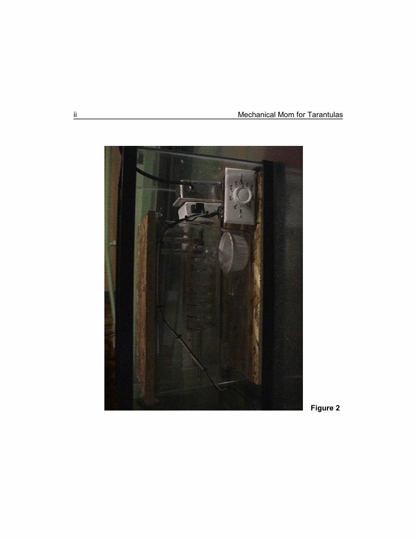
A Mechanical Mom at work.
Figure 2
Table of Contents
Table of Contents. . . . . . . . . . . . . . . . . . . . . . . . . . . . . . . . . . . . . . . . . . . . iiiFigures. . . . . . . . . . . . . . . . . . . . . . . . . . . . . . . . . . . . . . . . . . . . . . . . . . . . vIntroduction. . . . . . . . . . . . . . . . . . . . . . . . . . . . . . . . . . . . . . . . . . . . . . . . vii
The McKee Design. . . . . . . . . . . . . . . . . . . . . . . . . . . . . . . . . . . . . . viiThe Fostaty/Schultz Modifications. . . . . . . . . . . . . . . . . . . . . . . . . . . viiiBasic Philosophy. . . . . . . . . . . . . . . . . . . . . . . . . . . . . . . . . . . . . . . . . ixA Word of Warning. . . . . . . . . . . . . . . . . . . . . . . . . . . . . . . . . . . . . . . x
Chapter 1: Parts List. . . . . . . . . . . . . . . . . . . . . . . . . . . . . . . . . . . . . . . . . 13Chapter 2: Primary Enclosure. . . . . . . . . . . . . . . . . . . . . . . . . . . . . . . . . . 17Chapter 3: Baseboard and Timer Assembly. . . . . . . . . . . . . . . . . . . . . . . 21
Baseboard. . . . . . . . . . . . . . . . . . . . . . . . . . . . . . . . . . . . . . . . . . . . . 21Duplex Boxes. . . . . . . . . . . . . . . . . . . . . . . . . . . . . . . . . . . . . . . . . . 21Grounding. . . . . . . . . . . . . . . . . . . . . . . . . . . . . . . . . . . . . . . . . . . . . 22Timer Assembly.. . . . . . . . . . . . . . . . . . . . . . . . . . . . . . . . . . . . . . . . 24Clock Motor Assembly. . . . . . . . . . . . . . . . . . . . . . . . . . . . . . . . . . . . 27
Chapter 4: Inner Enclosure. . . . . . . . . . . . . . . . . . . . . . . . . . . . . . . . . . . . 29Specifications. . . . . . . . . . . . . . . . . . . . . . . . . . . . . . . . . . . . . . . . . . 29Keeping a Lid on It.. . . . . . . . . . . . . . . . . . . . . . . . . . . . . . . . . . . . . . 30The Art of Making Holes. . . . . . . . . . . . . . . . . . . . . . . . . . . . . . . . . . 30Air Conditioning. . . . . . . . . . . . . . . . . . . . . . . . . . . . . . . . . . . . . . . . . 31Initial Placement. . . . . . . . . . . . . . . . . . . . . . . . . . . . . . . . . . . . . . . . 32
Chapter 5: Brood Cups. . . . . . . . . . . . . . . . . . . . . . . . . . . . . . . . . . . . . . . 33Chapter 6: Getting the Point. . . . . . . . . . . . . . . . . . . . . . . . . . . . . . . . . . . 35
Hole Placement. . . . . . . . . . . . . . . . . . . . . . . . . . . . . . . . . . . . . . . . . 35The Axle and the Timer Switch. . . . . . . . . . . . . . . . . . . . . . . . . . . . . 36The Axle and the Clock Motor Assembly. . . . . . . . . . . . . . . . . . . . . . 37Axle Hole. . . . . . . . . . . . . . . . . . . . . . . . . . . . . . . . . . . . . . . . . . . . . . 39Axle Construction.. . . . . . . . . . . . . . . . . . . . . . . . . . . . . . . . . . . . . . . 39
Chapter 7: Thermostat Assembly. . . . . . . . . . . . . . . . . . . . . . . . . . . . . . . 41Preliminary Preparation. . . . . . . . . . . . . . . . . . . . . . . . . . . . . . . . . . . 41Electrical Preparation.. . . . . . . . . . . . . . . . . . . . . . . . . . . . . . . . . . . . 42Thermostat Position.. . . . . . . . . . . . . . . . . . . . . . . . . . . . . . . . . . . . . 43
iv Mechanical Mom for Tarantulas
Chapter 8: Heater Assembly. . . . . . . . . . . . . . . . . . . . . . . . . . . . . . . . . . . 47Chapter 9: Dimmer Switch.. . . . . . . . . . . . . . . . . . . . . . . . . . . . . . . . . . . . 51Chapter 10: Closing the Circuit. . . . . . . . . . . . . . . . . . . . . . . . . . . . . . . . . 53
Wiring for a Timer. . . . . . . . . . . . . . . . . . . . . . . . . . . . . . . . . . . . . . . 53Wiring a Clock Motor Assembly. . . . . . . . . . . . . . . . . . . . . . . . . . . . . 53Continuing the Circuit. . . . . . . . . . . . . . . . . . . . . . . . . . . . . . . . . . . . 56Grounding. . . . . . . . . . . . . . . . . . . . . . . . . . . . . . . . . . . . . . . . . . . . . 56
Chapter 11: How It Works. . . . . . . . . . . . . . . . . . . . . . . . . . . . . . . . . . . . . 59Chapter 12: Hygrometer Assembly. . . . . . . . . . . . . . . . . . . . . . . . . . . . . . 61
Theory. . . . . . . . . . . . . . . . . . . . . . . . . . . . . . . . . . . . . . . . . . . . . . . . 61Thermometers. . . . . . . . . . . . . . . . . . . . . . . . . . . . . . . . . . . . . . . . . . 62Installation. . . . . . . . . . . . . . . . . . . . . . . . . . . . . . . . . . . . . . . . . . . . . 63Application. . . . . . . . . . . . . . . . . . . . . . . . . . . . . . . . . . . . . . . . . . . . . 65
Chapter 13: Final Assembly. . . . . . . . . . . . . . . . . . . . . . . . . . . . . . . . . . . 67Chapter 14: Loose Ends. . . . . . . . . . . . . . . . . . . . . . . . . . . . . . . . . . . . . . 69
Troubleshooting.. . . . . . . . . . . . . . . . . . . . . . . . . . . . . . . . . . . . . . . . 69The thermostat's neon lamp fails to light altogether. . . . . . . . . . 69The heater bulb remains on all the time. . . . . . . . . . . . . . . . . . . 70Either the brood cups or the axle persistently comes unscrewed
.. . . . . . . . . . . . . . . . . . . . . . . . . . . . . . . . . . . . . . . . . . . . . 70Adjustments and Calibrations. . . . . . . . . . . . . . . . . . . . . . . . . . . . . . 71Variations. . . . . . . . . . . . . . . . . . . . . . . . . . . . . . . . . . . . . . . . . . . . . 72Day To Day Operation. . . . . . . . . . . . . . . . . . . . . . . . . . . . . . . . . . . . 75
Humidity Requirements... . . . . . . . . . . . . . . . . . . . . . . . . . . . . . 75Temperature Requirements.. . . . . . . . . . . . . . . . . . . . . . . . . . . 75Eggsac Maintenance.. . . . . . . . . . . . . . . . . . . . . . . . . . . . . . . . 75Record Keeping.. . . . . . . . . . . . . . . . . . . . . . . . . . . . . . . . . . . . 76
Remarks. . . . . . . . . . . . . . . . . . . . . . . . . . . . . . . . . . . . . . . . . . . . . . 76Bibliography. . . . . . . . . . . . . . . . . . . . . . . . . . . . . . . . . . . . . . . . . . . . . . . 79Index. . . . . . . . . . . . . . . . . . . . . . . . . . . . . . . . . . . . . . . . . . . . . . . . . . . . . 83
Figures
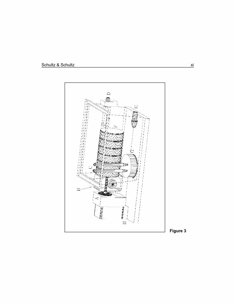
Figure 2 A Mechanical Mom at work.. . . . . . . . . . . . . . . . . . . . . . . . . . . iiFigure 3 Three dimensional drawing of the incubator... . . . . . . . . . . . . . xiFigure 4 An arrangement for the primary enclosure's glass lid... . . . . . 16Figure 5 Baseboard for the incubator.. . . . . . . . . . . . . . . . . . . . . . . . . . 19Figure 6 A bridge over a stationary hub on a timer dial.. . . . . . . . . . . . 26Figure 7 The end of the inner enclosure that faces the timer.. . . . . . . . 34Figure 8 The inner enclosure.. . . . . . . . . . . . . . . . . . . . . . . . . . . . . . . . 46Figure 9 Wiring diagram for the incubator.. . . . . . . . . . . . . . . . . . . . . . 55
vi Mechanical Mom for Tarantulas
We encourage you to use the blank spaces in this booklet for your own notes.
Arachnologists generally agree that the silken container produced by most1
spiders for their eggs is called an eggsac, as opposed to an egg case and oothecathat are firm walled containers.
Introduction
Several methods have been tried for hatching the eggs of tarantulas. Among themare leaving the eggsac (egg case ) with the mother, removing the eggsac from the1
mother to a separate container, removing the eggsac from the mother and thenremoving the eggs from the eggsac to a cloth cradle in a separate container(Turbang, 1993), and finally, removing the eggsac to an artificial, mechanicalincubator (McKee, 1984a, 1984b, 1986; Schultz and Schultz, 1998). Of thesemethods, an artificial, mechanical incubator is arguably the most reliable. A morecomplete discussion of these methods can be found in Schultz & Schultz, 1998.
The McKee Design
The design presented here is based on one first published by Mr. Al McKee (1986),but some important changes have been made.
The McKee design incorporated a nineteen liter (five gallon) aquarium as an"incubator containment housing" (his terminology, equivalent to our "primaryenclosure"). The incubator containment housing served as an insulating interfacebetween the surrounding room and an internal chamber. It also protected theworking mechanism of the incubator from accidental mis-adjustment.
Within this enclosure was a wooden board acting as the central spine for theworking mechanism. This mechanism was composed of a plug-in, electric timerswitch, and an inner enclosure ("incubation chamber") made from a plastic box. Ametal rod (hereinafter called the axle), was attached to the rotating face of the timerand passed through the side wall of the inner enclosure. Affixed to the inner end of
viii Mechanical Mom for Tarantulas
Current usage requires that the two words "egg" and "sac" be combined2
into one word.
the axle was a cylindrical plastic globe ("egg sac container" ). The incubation2
chamber also held an aquarium thermometer, night-light bulb, thermostat, humiditysensors, and a small dish of water.
The timer switch, a dimmer switch, the thermostat, a direct current converter andthe night-light bulb were all wired in series to produce a controllable heat source. Ifan external, additional heat source was to be placed under the aquarium, aseparate thermostat for it was also incorporated into the circuit.
In practice, the timer rotated the eggsac container once every twenty-four hours toprevent the egg mass from clumping. The thermostat, the ancillary electronics, andthe night-light bulb maintained a constant temperature. Humidity was maintained bymeans of the water in the small dish.
The Fostaty/Schultz Modifications
In collaboration with a friend, Mr. Michael Fostaty, and through several differentstages, these authors have made some important improvements in Mr. McKee'sdesign. Practice has shown that most of the ancillary electronics used by McKeewere not necessary. The single exception was the retention of a dimmer switch inthe circuit to decrease the intensity of heat radiated by the light bulb.
Additional modifications included the following.
1. A larger primary enclosure allowed multiple eggsacs in the incubator at thesame time.
2. The night-light bulb was replaced by a candelabra bulb because the largerincubator required more heat to maintain an adequate temperature, and night-light bulbs consuming more than eleven watts were not available.
3. An aquarium heater was substituted for the thermostat.
Schultz & Schultz ix
4. The single eggsac container, suggested by McKee, was replaced by a stackof plastic, screw-together, cup-like, fishing tackle boxes, allowing incubationof several eggsacs at once.
5. A simple wet bulb-dry bulb hygrometer (humidity gauge) was added as ameans of monitoring relative humidity. The humidifier dish was used as thesource of water for the wet bulb thermometer.
A photo of a working incubator is given in the frontispiece and a drawing is given inFigure 3. A detailed discussion of its construction follows.
Basic Philosophy
The underlying philosophy in the construction and operation of this incubator is thatit be as simple as possible and still accomplish the required tasks. Those tasks are
1. Protect the eggsac and its enclosed eggs from mechanical injury.2. Maintain the eggsac at a temperature that facilitates embryonic development.3. Maintain the eggsac at a minimum relative humidity to prevent the eggs'
dessication and death.4. Subject the eggs in the eggsac to a gentle stirring or jostling motion. (The
exact reason why this is necessary is still being debated. Such stirring,however, has proven to be absolutely necessary.)
Important design considerations are that the incubator be as uncomplicated andnon-technical as possible. For this we chose to incorporate (some would say"subvert") relatively common, off-the-shelf components available in almost anyhardware or department store or pet shop. The idea was that almost anyone couldbuild a serviceable incubator in their apartment with only a few very basic tools, andsuccessfully run the mechanism with little or no expertise or intense training.
It is entirely possible to add feedback mechanisms and integrated circuits orconnect the incubator to a computer for precise monitoring and control, use high-tech infrared heaters, fault alarms, remote controls, chrome plated components, astereo system, vibrating bed, etc., etc., etc. (Just kidding on the last few items, but
x Mechanical Mom for Tarantulas
you get the point), but all of these are not only unnecessary, they're alsoundesirable and almost always inordinately expensive. The more complicatedcomponents that are added, the more things there are to go wrong and the moredifficult and expensive the fault will be to repair.
A Word of Warning
Contained herein are descriptions of electric circuits, but the details of making theconnections are intentionally omitted. The prospective builder is strongly urged toseek the help of a professional electrician in fabricating them. All electrical workshould be inspected by a professional electrician and approved for safety before itis used.
These instructions are clearly biased towards North American voltages, electriccodes, and equipment. Many other parts of the world use different voltages, codes,and equipment, and modifications will have to be made to accommodate thesedifferences. Professional electricians and certified electrical engineers are the onlypeople qualified to make such design modifications safely.
The enthusiast who undertakes to construct this equipment must assume theresponsibility for the safety of the circuits produced. Because the details ofconstruction are not controllable by the authors, they cannot assume liability forthem.
SIMPLE IS BETTER.
Schultz & Schultz xi
Three dimensional drawing of the incubator.
Figure 3

xii Mechanical Mom for Tarantulas
We encourage you to use the blank spaces in this booklet for your own notes.
Chapter 1: Parts List
Following is a parts list for the major items required in the manufacture of anincubator. It is not exhaustive because it is assumed that the builder will have mostof the minor items available in the workshop. A full description and the significanceof each item will become apparent during the following discussion.
! Aquarium, fifty by twenty five by thirty centimeters (twenty by ten by twelveinches, nominally a ten gallon aquarium) or larger, referred to as theprimary enclosure in the discussion. We used a ten gallon aquarium inour examples.
! Rectangular box with lid. Transparent plastic. Referred to as the innerenclosure in the discussion that follows. We used a "Kritter Keeper" in ourexamples. See pages vii, 34 and 46.
! Glass plate, large enough to cover the aquarium. See page 16.! Plywood board. Referred to as the baseboard in this discussion. See page 21.! Duplex electrical boxes. Two are required. See page 21.! Duplex outlet with third conductor grounding and a matching duplex box cover.
See pages 21, 23 and 24.! Dimmer switch and a matching duplex box cover. See pages 21 and 51.! Timer Switch or clock motor assembly. See pages 21 and 24.! Duplex box blind plate, required only if a clock motor assembly is used instead
of the timer switch.! Electric wire, at least two meters (seven feet) of sixteen gauge insulated
copper wire colored green, and four meters (fourteen feet) in some othercolor. If possible, choose the multi-stranded variety because it is muchmore flexible and easier to work with.
! Electric power cord, three conductor, approximately two meters (six to sevenfeet) long. See pages 22 and 53.
! Alcohol, at least seventy percent isopropyl, methyl, or ethyl. Ninety or ninety-five percent alcohol is better.
! Adhesives. Epoxy glue, silicone aquarium sealer, and PVC plumbing cementare all used in the construction.
14 Mechanical Mom for Tarantulas
DO NOT USE SILICONE BATHTUB SEALER. The mildewcide in thispreparation is guaranteed to kill the tarantula's eggs.
DO NOT USE SILICONE CONSTRUCTION CAULK. These products do nothave sufficient bonding properties, and they may also contain mildewcides toprevent mildew growth.
! Threaded rod. This is referred to as the axle in the discussion. Acquire a pieceat least thirty centimeters (one foot) long. A diameter of about eightmillimeters (five-sixteenths inch) is satisfactory. Also acquire at least threehexnuts and three washers to fit this rod. See pages vii and 24.
! Drilling lubricant. Either a mild, liquid dish detergent, or salad oil. Notnecessary if holes in plastic are melted.
! Stacking, small parts boxes. Referred to as brood cups in the discussion.Purchase two sets of these, at least five individual cups are needed andmore are very handy. One may be used as a humidifier dish. See pagesix and 33 for more details.
! Candelabra lamp socket. Try to acquire one with as compact a means ofattachment as possible. See pages 47 and 73.
! Low wattage candelabra bulbs. Twenty-five watts is usually adequate for anincubator of the size made here. A larger incubator may require a higherwattage bulb. More information is available on pages viii, 42, 47, 59, 71and 73
! Aquarium heater. Any wattage is acceptable because the heating element willbe discarded. Details on pages viii and 41.
! PVC pipe. Used in both the plumbing and electrical trades. Acquire a piece atleast as long as the longest dimension of the inner enclosure (see above).This should have an inner diameter sufficient to safely accommodate theinternal parts of the aquarium heater. An explanation can be found onpage 43.
Schultz & Schultz 15
! Aquarium thermometers. Two identical ones are required. A commercial,electronic humidity gauge will also serve. See pages 47 and 61 for moreinformation.
16 Mechanical Mom for Tarantulas
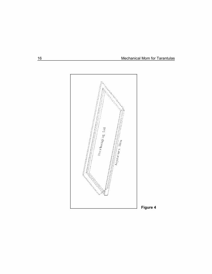
An arrangement for the primary enclosure's glass lid.
Figure 4
Chapter 2: Primary Enclosure
The primary enclosure's (equivalent to McKee's incubator containment housing)principal purposes are to prevent accidental contact with potentially dangerous parts(e.g., bare wires), to be a convenient receptacle for holding the whole mechanism,to protect the mechanical and electrical parts from damage or accidental mis-adjustment by either the enthusiast or the cleaning lady, and to allow extrainsulation against the ambient environment.
An aquarium makes a serviceable primary enclosure, and the following discussionwill assume one will be used. An aquarium with a cracked (but not missing) panewill work. At the very least, a cracked pane should be securely taped to prevent aloose piece of glass falling out, and to protect people moving around the incubator.If at all possible, repair a broken aquarium instead.
A glass plate is used as a lid for the aquarium. It should be of rather strong glassto prevent breakage. The minimum thickness is three millimeters (one-eighth inch),but five or six millimeter (three-sixteenths or one-fourth inch) is better. Some glassand glazing shops sell salvaged glass from broken patio doors and store fronts atreduced prices. Such discolored or scratched glass, cut to the appropriate size, iscompletely satisfactory. The novice who has little or no experience with cuttingglass, should consider having someone at the hardware store or glass shop cut itto the correct size. All sharp corners and edges must be removed with sandpaperor a fine emery stone as a safety measure.
In one arrangement, the lid will merely rest on top of the aquarium (Figure 4). Theadvantage with this arrangement is that the glass plate need not be cut to somespecific size. The disadvantage is that it may slide or be knocked off. An alternatearrangement consists of a glass plate that is cut to fit inside the lip of the frame ofthose aquaria that possess such a lip. The advantage here is that the glass platewill never slide off the top of the aquarium and shatter. The disadvantage is that thiswill require precision glass cutting, usually beyond the expertise of non-professionals.
18 Mechanical Mom for Tarantulas
To allow a place for the electric cord to pass through without inordinately disturbingthe lid, cut off one corner of the glass plate. The exposed opening should not beunduly large, however. A minor leak of cool air is acceptable. A major breach is notpermissible.
Multiple layer plywood will also work as a cover. However, single ply veneers, mostsolid wooden boards, chipboard, fiber board or sheets of acrylic plastic (e.g.,Plexiglas or Perspex), will quickly warp and become unserviceable.
Schultz & Schultz 19
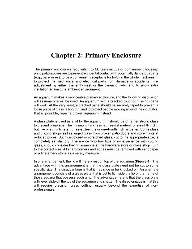
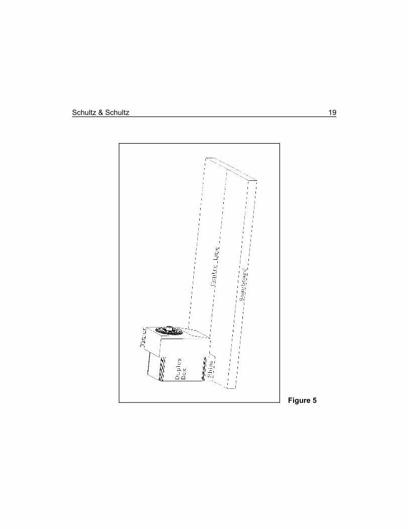
Baseboard for the incubator.
Figure 5

20 Mechanical Mom for Tarantulas
We encourage you to use the blank spaces in this booklet for your own notes.
Chapter 3: Baseboard and TimerAssembly
Baseboard
The spine of the mechanism is made of a piece of wood and is called thebaseboard. Nineteen millimeter (three-quarters inch) plywood is best because it isdimensionally stable under varying temperatures and humidity, and also becauseit won't bend or distort when picked up or moved. Its length and width should besuch that it will lay flat on the bottom of the aquarium and still leave at least anineteen millimeter (three-quarters inch) margin of the aquarium's bottom exposedon all four sides. Sand or plane all edges to remove all roughness and slivers.Varnishing or painting is ordinarily not required, but if it is done, spar varnish,urethane varnish, or a moisture resistant paint should be used. Allow the finish tocure thoroughly before proceeding with construction, permitting any residual,potentially harmful solvents to dissipate before using the incubator.
Duplex Boxes
Standard, duplex, electrical boxes are used to securely hold the duplex outlet andtimer or clock motor assembly, and the dimmer switch. Metal boxes are assumedhere. If other varieties are used (e.g., PVC) appropriate alterations in this designmust be made to allow for adequate grounding and to allow for the other details ofconstruction.
Metal duplex boxes normally have several holes incompletely stamped in theirsides. Each hole is still plugged with the metal disk that would be expected to beremoved during the stamping process. The metal disks that plug them are calledknockouts or slugs. These are intended to allow the worker to determine thelocation of exit ports for wires from the box for any particular electrical project. PVCduplex boxes have similar arrangements for producing the required holes.
22 Mechanical Mom for Tarantulas
Remove one of the knockouts from the side or back of one of the duplex boxes. Allelectrical wiring should be run through this hole.
To protect the insulation on the wires that will be passing through these openings,any remaining burrs may carefully be filed away with a rat tail file. However, whileusing a file to remove burrs from the edges of the knockout holes will work, it isn’toptimal because the edges of the metal can still abrade the insulation on the electricwires over time. A much preferable method is to use rubber grommets in theseholes, available from electronics supply and hardware stores.
This box should be installed on one end of the baseboard. It should be oriented withits long axis vertical and its open side facing the opposite end. It should be centeredexactly on the center line of the baseboard.
Use two small wood screws to secure the duplex box and to allow for futureadjustments. If the duplex box does not already have acceptable holes punched forthe purpose, they must be drilled. These holes should be large enough to easilypass the screws that will be used. Drill the holes adjacent to the open side to alloweasy access with a screwdriver.
The duplex box may have to be raised with shims to allow a minimal clearancebetween the subsequent electrical parts and the baseboard. See Figure 5 and thediscussion on pages 24, 37 and 38.
An additional duplex box to hold a standard household dimmer switch will also befastened to the baseboard, but its position must be determined later. This secondbox should be prepared in the same manner as the first.
Grounding
An electrical grounding wire is strongly recommended for all actual and potentialelectrical conductors. This amounts to all metallic objects in the incubator. A threewire, grounded power cord should definitely be used. At the very least, the thirdgrounding wire should be attached to the duplex box by way of one of the box'
Schultz & Schultz 23
mounting screws. Duplex outlets should possess grounding capability and a jumperwire should connect the grounding screw to the same mounting screw on the duplexbox. All grounding wires should be green or the color mandated by local electricalcodes. (Green is the color specified by the electrical code in North America.)
Figure 9 is a schematic for the wiring of this incubator. It is presumed that theaquarium heater (used only for its thermostat) will also have a third wire ground,although this is not always so. In that figure, the ground wires are represented bydashed lines.
If the home wiring system does not include a third wire as a ground, use a specialgrounding adapter to ground the power plug to the electric mains box. If this is notpossible, it is extremely important that a professional electrician by consulted.
Recent reports by enthusiasts are that many electrical timers currently available(winter of 2006-2007) are made overseas and are not sturdy enough to last inthis application more than a few weeks or months. The prospective buildershould plan ahead for this eventuality by stocking several, identical, customizedtimers for an emergency replacement, and closely monitor the incubator daily ormore frequently to confirm proper rotation.
If timers manufactured in the United States or more serviceable heavy dutytimers can be found, they should be substituted instead.
If none of this is possible, a free standing synchronous motor (described below)may be the best alternative option.
24 Mechanical Mom for Tarantulas
BEWARE: Alcohol at 70% strength is dangerously flammable. At 90%strength, it is explosive, akin to gasoline. Do not use alcohol in the presenceof any source of ignition (e.g., flames or pilot lights, lit cigarettes, sparks fromelectrical equipment, etc.). Use only in an area of good ventilation.
Timer Assembly
If a timer is to be used, it should be a type that bears a circular, rotating dialrevolving every twenty four hours. No other variety will work in this application. Thetimer does not turn the unit on or off, as one might at first assume, and any switchmechanisms are completely irrelevant. It is used solely for its built-in synchronousmotor as a convenient source of rotary power for tumbling the eggsac on a twenty-four hour schedule. Set the appropriate switch for permanent "on," "override," or"continuous" operation and secure it with a piece of tape if necessary.
The timer is plugged into a standard, duplex electrical outlet that is, in turn, mountedin the first standard, duplex electrical box. Compare the timer/outlet assembly to theduplex box. If the box requires shimming to allow the timer to clear the baseboard,do it now. (See Figure 5 and the discussion on pages 22, 37 and 38.) Use smallrectangles of veneer, plywood, or solid wood for shims. The top and bottomsurfaces of the shims must be parallel (as opposed to wedge-shaped) to ensurethat the duplex box remains exactly vertical. See Figure 5. Be forewarned thatfurther shimming adjustments will probably be necessary later. Do not permanentlyfasten these parts in place.
If conditions necessitate, it is possible to mount the timer upside down or in someother orientation with no ill effects so long as the center of the timer's dial remainsexactly above the baseboard's centerline.
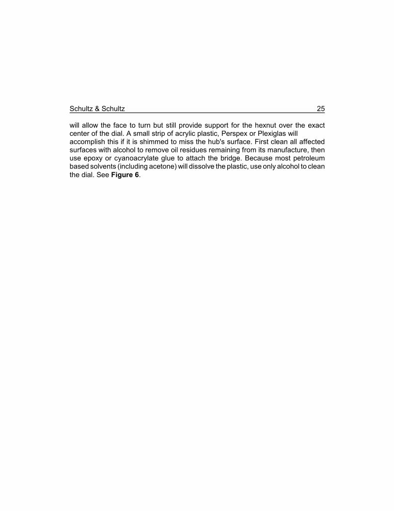
A hexnut must be attached to the center of the timer's face to accept the threadedaxle rod. If the timer has a stationary central hub, a bridge must be improvised that
Schultz & Schultz 25
will allow the face to turn but still provide support for the hexnut over the exactcenter of the dial. A small strip of acrylic plastic, Perspex or Plexiglas will accomplish this if it is shimmed to miss the hub's surface. First clean all affectedsurfaces with alcohol to remove oil residues remaining from its manufacture, thenuse epoxy or cyanoacrylate glue to attach the bridge. Because most petroleumbased solvents (including acetone) will dissolve the plastic, use only alcohol to cleanthe dial. See Figure 6.
26 Mechanical Mom for Tarantulas
A bridge over a stationary hub on a timer dial.
Figure 6
Schultz & Schultz 27
To attach the hexnut, use a cotton swab and alcohol to clean the plastic on thecenter of the dial or bridge. As above, petroleum based solvents such as acetonewill not work here because they will dissolve the plastic. Wash the hexnut with cleanalcohol to remove all traces of oil. Apply a thin layer of epoxy glue to the back sideof the hexnut. Be very careful at all stages not to get any of the glue into the threadsof the hexnut. Apply another thin layer to the center of the dial's face or the bridge.Carefully position the hexnut in the dial's center. Prop the timer up so that the dialis perfectly horizontal, and carefully apply a small piece of tape to stabilize thehexnut. This will prevent it from slipping off center before the glue sets. After thebond is secure (wait at least twenty four hours), apply a little more glue around theperiphery of the hexnut. Allow the bond to cure an additional twenty four hours.
After the glue is thoroughly set, carefully plug the timer into the duplex outlet in itspreferred orientation.
Clock Motor Assembly
In essence, the timer switch is used only for its synchronous motor, and suchmotors with the associated gear works are available in a variety of other forms (e.g.,salvaged from an old clock or purchased from local electronics, clock repair, hobby,or crafts stores). If such a clock motor assembly is available, it may be used in placeof a timer. Given a choice, choose one that produces the most rotational power ortorque.
It is difficult to give precise instructions when using clock motor assemblies becauseof their many different sizes and designs, and the builder must exercise someingenuity in installing them.
The face of the clock motor assembly usually has a central pin and two concentricsleeves of descending lengths on which the clock's hands would normally beattached. The outer sleeve usually moves the hour hand, and this is the one ofinterest to us.
28 Mechanical Mom for Tarantulas
The entire assembly is very fragile and great care must be exercised when workingwith it. The tolerances between the sleeves and the central pin are very close.Deforming them in any way will cause them to bind, stopping the motor. Noadhesive must be allowed to bind the sleeves to the outer casing, to each other, orto the center pin during fabrication.
Attaching the axle to the outer sleeve so that it will rotate every twelve hours posesa difficult engineering problem. One possible strategy utilizes a short piece of vinyltubing of just large enough diameter to fit snugly over the end of the axle. WITH
GREAT CARE the hour hand sleeve can be shimmed up with vinyl tape to theappropriate diameter to snugly accept the piece of vinyl tubing. Alternatively, two orthree sizes of vinyl tubing of descending inner and outer diameters may be stackedwithin each other to produce a shaft of the proper diameter.
A more professional appearing arrangement might be had by soldering severalcopper or brass tubes (available from hobby and crafts stores) of varying diametersinside each other as an adapter. Attach the adapter to the hour hand sleeve with asmall drop of epoxy or cyanoacrylate glue. This adapter should be threaded toaccept the axle on the other end. It is absolutely imperative that this adapter be assmall and light as possible. Again, be very careful not to glue the motor's sleevestogether.
Installing the clock motor assembly on the duplex box should be postponed untillater because the exact position of the motor is not yet predictable. For now, set theclock motor assembly aside, in a safe place, cover the face of the duplex box withthe blind plate, and proceed with the construction of the remainder of the incubator.
Chapter 4: Inner Enclosure
Specifications
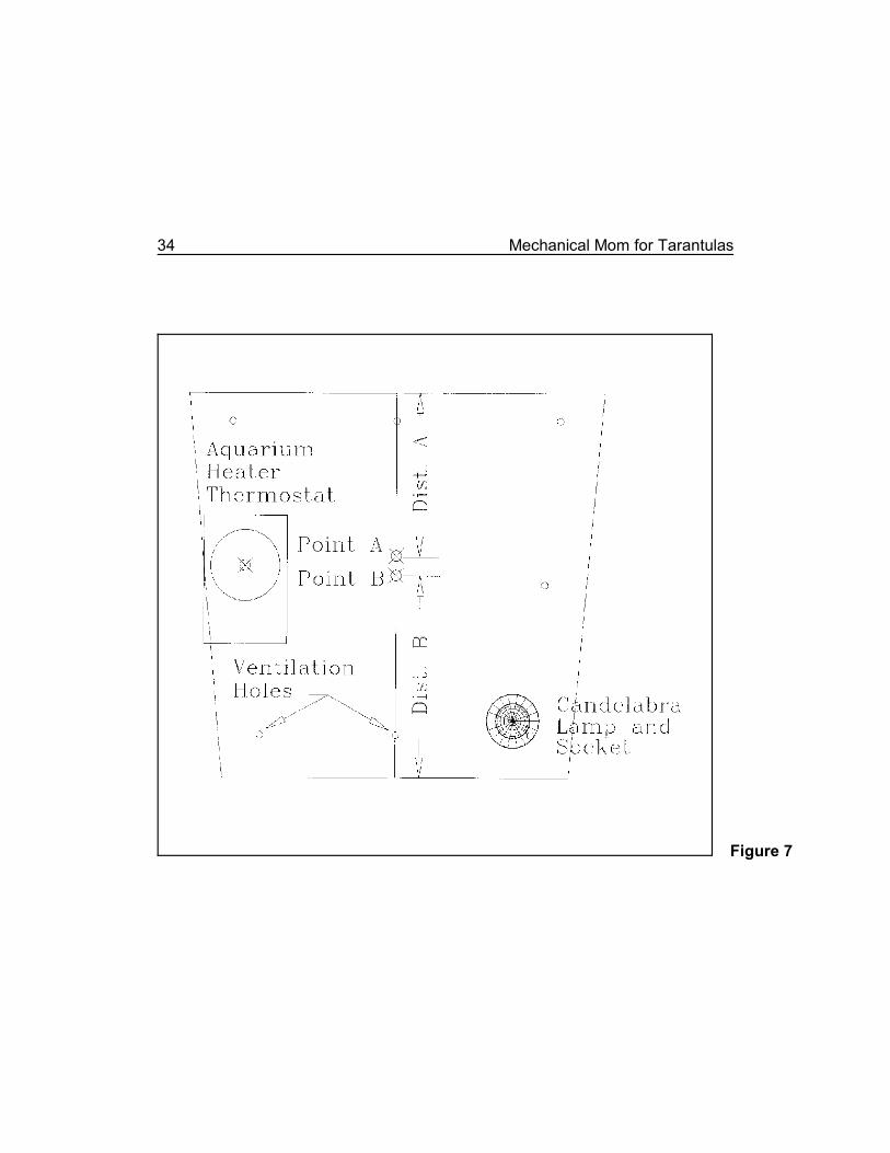
The inner enclosure is a constant environment chamber, the "incubation chamber"of McKee. McKee recommends a plastic food container, and most enthusiasts whohave built these incubators use just that. It is also possible for the enthusiast to buildone from Perspex or Plexiglas to custom dimensions. In the example given here,a seven and one-half liter, rectangular, plastic, aquarium (e.g., "Kritter Keeper,"readily available from pet shops) was used. Note that this container (Figure 7 andFigure 8) has sloping walls, adding another level of complexity to the construction.The distinct advantage to using one of these is that they are readily available atalmost any pet shop or pet department.
The minimum size is fifteen centimeters wide by fifteen centimeters long by twentycentimeters high (six by six by eight inches). The height of the inner enclosure mustallow at least nineteen millimeters (three quarters inch) clearance between its lidand any of its contents, and at least nineteen millimeters (three quarters inch)clearance between the inner enclosure lid and the glass plate covering theaquarium when the inner enclosure is setting on the baseboard. The maximumallowable width must allow at least a two and one-half centimeter (one inch)insulating space between the inner enclosure and the aquarium walls on both sides.The inner enclosure should be as long as possible and still allow ample roombetween it and the timer for the dimmer switch's duplex box, and allow at least a twoand one-half centimeter (one inch) space between the end of the inner enclosureand the corresponding end of the aquarium (primary enclosure).
If the head of the aquarium heater protrudes beyond the end of the inner enclosure(see below), additional space must also be apportioned to allow appropriateclearance.
30 Mechanical Mom for Tarantulas
Keeping a Lid on It.
The inner enclosure must have an environmentally tight lid, but not so tight as tomake it difficult to open in cramped quarters. Many plastic containers come withserviceable lids from the manufacturer. However, the plastic aquarium that wasused in our example had a lid made in the shape of a domed grid that wascompletely unsatisfactory. In this instance, a new lid had to be made. Anyconvenient material that wouldn't warp or degrade on exposure to warmth andhumidity could have been used. See page 18 for a discussion of acceptablematerials.
In our example, a piece of nine or ten millimeter (three-eighths inch) thick, allweather plywood, just large enough to completely cover the inner enclosure, wasused. A rabbet was cut around its circumference on the bottom side in such a waythat it was partly inset into the top of the inner enclosure. This prevented the coverfrom accidentally becoming misaligned or sliding off.
The Art of Making Holes
At several points during the construction of the inner enclosure it will be necessaryto make holes or perforations in the plastic. McKee (1986) recommends drillingthem. If these holes are to be drilled, to prevent the plastic from breaking, use a littlesalad oil or liquid dish detergent as a lubricant (McKee, 1986). Use a new, sharpdrill bit. Advance the drill bit very slowly. It must shave a hole in the plastic, notgouge it. A drill press is strongly recommended for this task.
The holes were melted in the example shown here. Nails and metal rods were usedto make the smaller holes (less than five millimeters, three-sixteenths inch). Thelarger holes were melted with metal tubes and plumbing adapters. The metal pieceswere heated on a kitchen range, but a propane torch will also work. Use a pair ofstout pliers to hold the hot metal and be ever cautious of burning yourself or setting flammable clothing, tools and furnishings on fire. There is a strongargument in favor of keeping a fire extinguisher handy.
Schultz & Schultz 31
When melting such holes, the side of the hole from which the hot metal enters willhave a small, elevated ring of plastic encircling it where molten plastic is pushedaside by the advancing metal. Where flat surfaces are required, melt the hole fromthe opposite side or carefully shave the ring off using a stout, sharp knife or a file.
Air Conditioning
Drill or melt at least eight ventilation holes in each of the four sides of the innerenclosure. At a minimum, arrange them with one close to each corner and onealong the middle of each side's edge. Place them about twenty millimeters (three-quarters inch) from the edges of the face. Refer to Figure 7 and Figure 8 forillustrations of their suggested positions. Additional holes may be placed whereconvenient. It is better to make too many than too few. If too many holes are meltedor drilled, the extras may be easily covered with tape. However, if too few are made,correcting the error may require dismantling the incubator and upsetting all theadjustments.
Make these holes two millimeters (approximately one-sixteenth inch) in diameter.Making the holes larger than this may allow the smaller, newly hatched tarantulasenough room to escape. It is better to make more holes than to make them toolarge.
Figure 7 and Figure 8 are diagrams of the end of the inner enclosure that faces thetimer. They indicate the relative positions of the aquarium heater thermostat, thecandelabra bulb heater (as seen from the opposite end), and the small ventilationholes. The line scribed up the center of the face and points A and B are describedbelow.
32 Mechanical Mom for Tarantulas
Initial Placement
Drill or melt two holes in the bottom of the inner enclosure. These should be justlarge enough to accommodate one and one-half centimeter long (five-eighths inch),round head wood screws. They may be placed anywhere convenient, but at leastten centimeters (four inches) apart.
Place the inner enclosure on the baseboard, exactly in its final position, keeping inmind the clearances mentioned several paragraphs earlier, square with the edgesand centered on the baseboard's center line. Carefully mark the position of thescrew holes in the bottom of the inner enclosure on the baseboard. Remove theinner enclosure and drill pilot holes in the baseboard on these marks. Replace theinner enclosure, double check the alignment, and lightly screw it back in place withthe wood screws. Caution: over-tightening the screws can crack the plastic. Whilethis is not a serious fault, it does detract from the appearance of the incubator andbespeaks of poor workmanship.
It is important not to permanently fasten the inner enclosure in place just yet. It willhave to be removed and replaced several times before the incubator is completed.
Chapter 5: Brood Cups
Fishing tackle stores, craft stores and hobby shops sell small, inexpensive, styreneor acrylic screw-together jars for the purpose of storing small items such as fishhooks, pins and needles, and nuts and bolts. Each is a straight-sided cup, with malethreading around the top, and an indented base with matching female threading.Thus, one cup will thread into the bottom of the next in a tubular series. Onecommercial name for these is Stacking Tackle Boxes. A minimum of five cups willbe required, and two or three extra are a good idea. The medium size will work forsmaller eggsacs, but the large (nine centimeters, or three and three-quarters inchdiameter) is much more serviceable. If available, choose a brand that also suppliesa matching lid. From this point forward we will call these brood cups.
Drill or melt a ten millimeter (three-eighths inch) hole in the center of the lid. If a lidwas not included, use one of the cups, instead. But, in the discussion that followsyou must reverse the orientation of the remaining cups to compensate for thereversed gender of the threading.
Drill or melt eight holes, each one being two millimeters (one-sixteenth inch) indiameter, centered around the sides of all but two cups. These last, undrilled cupswill be used as the humidifier dishes.
MELTING HOLES is discussed in detail on page 30.
34 Mechanical Mom for Tarantulas
The end of the inner enclosure that faces the timer.
Figure 7
Chapter 6: Getting the Point
This section deals with the proper placement of the axle hole in the end wall of theinner enclosure and the proper placement of the timer or clock motor assembly.There seems to be no easy method for describing these procedures, at least in theEnglish language, and the reader is advised to examine the following discussionone sentence at a time, to follow the meaning and directions.
Hole Placement
There are several distances that are critical in the placement of the hole throughwhich the axle turns. The brood cups must be placed so that their rotation is nothindered by contact with any of the other objects within the inner enclosure.Because their position is uniquely defined by the placement of the axle that rotatesthem, the position of that axle is also critical. Because the position of that axle isdetermined almost solely by the position of the hole in the inner enclosure's wall, itfollows that the position of that hole is equally critical.
Measure the diameter of the cups. Divide this measurement by two and add onecentimeter (one-half inch). We will call this distance A. This is the minimum distanceallowable between the axle and the lowest point on the inner enclosure's cover toallow adequate clearance for the brood cups.
MACHINIST'S AND CARPENTER'S LAMENT
Measure twice.
Cut once.
YOU'VE BEEN WARNED!
36 Mechanical Mom for Tarantulas
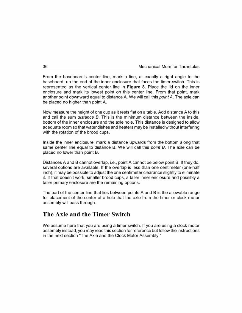
From the baseboard's center line, mark a line, at exactly a right angle to thebaseboard, up the end of the inner enclosure that faces the timer switch. This isrepresented as the vertical center line in Figure 8. Place the lid on the innerenclosure and mark its lowest point on this center line. From that point, markanother point downward equal to distance A. We will call this point A. The axle canbe placed no higher than point A.
Now measure the height of one cup as it rests flat on a table. Add distance A to thisand call the sum distance B. This is the minimum distance between the inside,bottom of the inner enclosure and the axle hole. This distance is designed to allowadequate room so that water dishes and heaters may be installed without interferingwith the rotation of the brood cups.
Inside the inner enclosure, mark a distance upwards from the bottom along thatsame center line equal to distance B. We will call this point B. The axle can beplaced no lower than point B.
Distances A and B cannot overlap, i.e., point A cannot be below point B. If they do,several options are available. If the overlap is less than one centimeter (one-halfinch), it may be possible to adjust the one centimeter clearance slightly to eliminateit. If that doesn't work, smaller brood cups, a taller inner enclosure and possibly ataller primary enclosure are the remaining options.
The part of the center line that lies between points A and B is the allowable rangefor placement of the center of a hole that the axle from the timer or clock motorassembly will pass through.
The Axle and the Timer Switch
We assume here that you are using a timer switch. If you are using a clock motorassembly instead, you may read this section for reference but follow the instructionsin the next section "The Axle and the Clock Motor Assembly."
Schultz & Schultz 37
Carefully measure the distance between points A and B. Exactly midway betweenthem, mark another point that we will call point C. Point C is the point on which wewill center the hole for the axle. Measure the vertical distance between point C andthe baseboard, and call this distance C. This is the distance that the center of thetimer's dial must lie above the baseboard in order to ensure that the axle is exactlyparallel to the baseboard.
If the center of the timer's dial lies below point C (i.e., the distance from the centerof the timer's dial to the baseboard is smaller than distance C), any shims under thetimer/duplex outlet/duplex box assembly must be adjusted to raise the timer to theappropriate level.
If the center of the timer's dial lies above point C, either the shims under the duplexbox must be adjusted, the inner enclosure must be shimmed to increase it'sdistance above the baseboard, or a taller inner enclosure must be pressed intoservice. Watch carefully to ensure that adequate distance is maintained betweenthe inner enclosure's lid and the lid of the primary enclosure. Another strategy tolower the timer is to mount it (and its associated duplex outlet and box assembly)upside down or on its side and shim it to the proper height.
After adjusting these heights with the various shims, the center of the timer dialmust be exactly as high above the baseboard as point C. Remeasure the height ofthe center of the hexnut on the timer's face above the baseboard, and remeasurepoint C on the inner enclosure's face to confirm this.
The Axle and the Clock Motor Assembly
This section is important only if a clock motor assembly is used in place of a timer.Those using a timer can skip to the next section “Axle Hole” .
The axle linking the clock motor assembly to the brood cups must be exactly parallelto the baseboard. Mounting the clock motor assembly to achieve this will requiresome ingenuity.
38 Mechanical Mom for Tarantulas
KNOCKOUTS are discussed on page 21.
If there are mounting screws at the back of the motor, drill corresponding holes inthe duplex box' blind plate at the appropriate level and mount the clock motorassembly on its outside face. If the screws are on the front of the clock motorassembly, corresponding holes must be drilled into the blind plate, plus oneadditional hole for the pin and sleeves on which the axle will be fastened. In thiscase, the clock motor assembly would be mounted to the back of the blind plate,inside the duplex box with the pin and sleeves protruding through the extra hole.
If such screws do not exist or if there isn’t enough room in the duplex box for themotor, improvise some other SECURE method of attachment at the correct height.If at all possible, any such attachment should allow for future adjustments in heightabove the baseboard.
The wires conducting electric power to the clock motor assembly should bethreaded through one of the knockout holes in the duplex box' side.
Mark a point midway between points A and B. We shall call this point C. Measurethe distance from point C down to the baseboard. We shall call this distance C. Thisis the ideal height of the center pin (on which the second hand was mounted) of theclock motor assembly. Mount the clock motor assembly so that the center pin isexactly at this height. If for some reason, the clock motor assembly's center pin ishigher than point A, the inner enclosure must be shimmed appropriately. (Watch theoverhead clearance between the inner and primary enclosures!) If the center pin ofthe clock motor assembly is lower than point B, shim the duplex box, or remountthe clock motor assembly a corresponding distance higher. Most clock motorassemblies will work in any orientation. Would mounting it upside down or on itsside place the center pin the correct distance from the baseboard? Remeasureagain to confirm that the axle will be exactly parallel to the baseboard.
Schultz & Schultz 39
Axle Hole
Remove the inner enclosure and drill or melt a hole approximately ten millimeters(three-eighths inch) in diameter at point C.
To protect this hole from wear by the axle, glue a washer of appropriate innerdiameter over the hole. This washer should be large enough to easily pass the axlethrough its center hole without excessive space. With this small embellishment, theaxle will ride on the wear resistant washer rather than the plastic. This will preventhaving to replace the entire inner enclosure once a year. Refer to Figure 7 andFigure 8.
Fasten the washer in place with silicone aquarium sealant or epoxy glue. But firstwash any oil residues or soil off the inner enclosure around the hole with alcohol.Also, rinse any oil residues off the washer with alcohol. As before, do not useacetone or any other petroleum based solvent on the plastic.
Axle Construction
With the inner enclosure screwed to the baseboard, measure the distance betweenthe center of the hexnut that is glued to the timer dial, or the center pin on the clockmotor assembly, and the near end of the inner enclosure. Add three centimeters(one and one-quarter inches), and cut the axle to this length. It is a good idea toscrew two of the hexnuts onto this rod before making the cut. After making the cut,lightly file off any burrs. Then unscrew one of the hexnuts over the cut end. Removeany remaining burrs a second time with a fine file or fine emery cloth, then unscrewthe second hexnut. This will help to maintain the threads on the rod.
MELTING HOLES is discussed in detail on page 30.
40 Mechanical Mom for Tarantulas
Temporarily install the axle by feeding it through the hole in the inner enclosure andthreading it into the timer dial hexnut or clock motor assembly's sleeve. Caution:Tightening the axle rod too forcefully into the hexnut can loosen the hexnut from theglue that fastens it.
On the rod, inside the inner enclosure, thread a hexnut almost all the way to theinner enclosure's wall. Leave about one centimeter (one-half inch) clearance. Slideon a washer. Slide on the brood cup lid (see page 33). The threaded side of the lidshould be facing into the inner enclosure, not towards the wall. Slide on anotherwasher, then the last hexnut. Adjust the position of the two hexnuts to allow onlyabout one centimeter of clearance (about one-half inch) between the wall of theinner enclosure and the brood cup lid. No more than one-half centimeter (three-sixteenths inch) of the rod should protrude past the hexnut, into the brood cup. Thismay require cutting an additional short length from the axle. Carefully tighten thelast hexnut finger tight. Screw as many of the brood cups onto the lid as room willallow.
Chapter 7: Thermostat Assembly
Preliminary Preparation
Acquire a common aquarium heater from a local pet or aquarium store. Choose oneof medium price. Very low priced models will prove to be a continuing source ofvexation, being difficult to adjust properly. Very high priced models have little tojustify their added expense for our purposes. If possible before purchasing theheater, remove each brand of heater from its packaging and try to turn thetemperature adjustment knob. Choose a heater that allows an easy, smoothadjustment without binding.
The rated wattage is irrelevant because of the alterations that will be made to it, butits length is critical. It can be no longer than the inside length of the inner enclosure.The aquarium heater should also have a glass test tube jacket that is easilyremoved. Finally, it is important that the aquarium heater parts be constructed tomaintain their integrity without this jacket.
Carefully dismantle the aquarium heater's top housing (head), laying the parts outin some orderly fashion so as to allow easy reassembly later. Most aquariumheaters possess a clamping mechanism to secure them to the aquarium's edge. Itwill be necessary to remove those parts. On some units, the clamping mechanismwill merely unscrew or drop out when the aquarium heater's casing is disassembled.With others, it will have to be removed using a fine toothed saw. Work slowly andcarefully so as not to break the plastic parts. If necessary, file the remaining burrsfrom the aquarium heater's housing to create a flat, even surface.
Remove and discard the glass tube. If left on the aquarium heater it would insulatethe thermostat from the temperature in the incubator. If the various parts of theaquarium heater tend to fall out of alignment without the glass jacket, try usingsome of the nylon cable ties used by electricians and handymen to secure the parts.If this doesn't work, purchase a different aquarium heater.
42 Mechanical Mom for Tarantulas
ELECTRICAL CONNECTIONS: See important comments regarding theconstruction of electrical connections on page x.
Electrical Preparation
Cut the wall plug from the end of the aquarium heater's power cord leaving a fewcentimeters of cord attached to the plug. Split the power cord on the heaterlengthwise to separate the various electrical conductors all the way back to theheater's head. Be very cautious not to damage the insulation on any of theseconductors; the insulation must remain intact around each separate conductor.
If the aquarium heater has a power cord with three conductors, one of them issurely a grounding wire. Some ingenuity and careful examination may be requiredto identify which one, but it MUST be identified if it exists. This may require dissectingthe wall plug (hence our suggestion that you leave a few centimeters of the cordattached as you cut it off) or carefully dismantling the aquarium heater's mechanismto determine which conductor is not connected to the electric circuit. If in doubt, takethe mechanism to a professional electrician for clarification. Once identified, thisground wire must be unambiguously labeled and later connected to the otherground wires in the incubator.
Remove the aquarium heater's heating element. In some models this will merelyrequire unplugging it, in others it must be unsoldered. If all else fails, cut it off usingwire cutters. In its place, insert a short, U-shaped, length of copper electrical wireas a jumper. Solder the connections to prevent accidental loosening. A little later,the missing heating element will be replaced with a low wattage bulb, but the bulbwill occupy a different position in the electrical circuit.
From this point forward we shall refer to the aquarium heater as simply thethermostat because we have disabled all of its other functions, and because we donot wish to confuse it with the candelabra bulb that we will be improvising as a heatsource.
Schultz & Schultz 43
Thermostat Position
We must now determine the position of the thermostat. In our example, thethermostat is mounted inside the inner enclosure in the end wall that is opposite thetimer, and placed at about the same level as the brood cups, but behind them.
Two orientations of the thermostat were tried: with the head on the opposite end ofthe inner enclosure from the timer, and on the same end as the timer. Mounting thehead away from the timer has the effect of uncluttering the area around the timerand possibly allowing easier adjustment of the thermostat, but exposes it to possibleaccidental misadjustment if the inner assembly should shift within the primaryenclosure. Mounting the thermostat’s head on the same end as the timer couldmake it more difficult to adjust, but will also make a more compact assembly ifspace is at a premium. In this example, we place the thermostat’s head away fromthe timer, but this is matter of personal preference rather than rational engineering.
The thermostat will lie inside a piece of slotted PVC pipe (see below) and sufficientspace must be allowed for the added diameter. In addition, it should not lie againstthe outside wall of the inner enclosure to avoid a perturbation in the temperaturethat it senses.
Pay particular attention to the position of the thermostat's head. It must not protrudefar enough in any direction to obstruct or interfere with the placement of theincubator assembly in the aquarium, or with any of the other mechanisms in theincubator.
On both ends of the inner enclosure, lightly mark the center of the thermostat'sproposed location, and draw circles around those points equal to the outsidediameter of the PVC pipe. Verify that, when the pipe is installed in this position, itwill not interfere with any of the inner enclosure's contents, particularly the broodcups, and there will be at least one centimeter (one-half inch) clearance betweenthe pipe and the wall of the inner enclosure. If possible, a clearance of at least twocentimeters (three-quarters inch) should also exist between the pipe and the broodcups.
44 Mechanical Mom for Tarantulas
Acquire a length of plastic or PVC pipe of the sort used in plumbing or electricalwork. This pipe will be used as a protective covering to hold the exposed electricalparts of the thermostat. For safety's sake this must be a non-conductive plasticpipe, NOT a metal one. The pipe should have an inside diameter sufficient toaccommodate the mechanism of the thermostat without disturbing or damaging it.
Cut a length from the stock piece of PVC pipe that is just slightly longer than theinside length of the inner enclosure at the level at which it will be mounted. Lay apiece of moderately coarse sandpaper or emery cloth (e.g., 80 grit) on a flat surfaceand rub the ends of the pipe across it to shorten the pipe in very small decrements.Test the length of the piece often. The ideal length will allow the pipe to fit into theinner enclosure snugly but without deforming the walls. In our example, the wallsof the inner enclosure are slightly sloped, and the ends of the pipe were sloped tomatch.
Before installing the pipe, cut numerous slots in it with a saw for ventilation. Theseshould be spaced approximately one centimeter (one-half inch) apart and shouldonly extend half way through the diameter of the pipe. They should be staggeredwith one cutting into the pipe from one side and the next cutting from the other sidea little farther along its length. Each slot need only be the width of one saw kerf. Analternate method is to drill a multitude of six millimeter (one-fourth inch) holes alongthe pipe’s length. In either case, drilling or sawing on a curved surface, great caremust be used to prevent your accidental injury. A simple jig constructed of two stripsof scrap wood nailed to a board with the PVC pipe laid between them will work wellto secure the pipe.
Using PVC plumbing cement or epoxy glue attach the piece of ventilated plasticpipe to the inside of the inner enclosure, centered over the locating marks. Makedoubly certain that it lies in its intended position and orientation. Brace, tape, orclamp it while the adhesive cures. Give the adhesive plenty of time to cure beforeproceeding.
Schultz & Schultz 45
A hole must now be made in the end of the inner enclosure, at one end of the PVCpipe, for the thermostat. After much experimentation (and many failures), theseauthors discovered that the best system employed a piece of thin walled, metaltubing of appropriate diameter to melt the hole. The most difficult part of the processwas finding a piece of metal tubing of the correct diameter. In the example shownhere, one end of a copper plumbing reducer coupling was the exact size needed,but any other thin walled metal pipe (e.g., a metal curtain rod) of the correctdiameter would have worked. Allow plenty of time for the metal tube to reach amaximal temperature. Work slowly and carefully to produce a clean, round hole thatopens directly into the inside of the PVC pipe.
Insert the thermostat assembly through the hole in the wall of the inner enclosureand into the pipe. The thermostat's control (head) should remain outside the innerenclosure for ease of adjustment, but the internal mechanism should lie entirelyinside the PVC pipe, inside the inner enclosure. Refer to Figure 7 and Figure 8.Fasten the thermostat securely in place using silicone aquarium sealant. Thisshould be done in such a way as to exclude all cool air leaks from around its baseor connection. Again, review the requirements for its position and tape or prop itsecurely while the silicone aquarium sealant cures.
We strongly recommend the use of silicone aquarium sealant in this application fortwo reasons. First, it is a space filling adhesive that will effectively seal any smallleaks around the thermostat's head. And, it can be cut with a knife, scalpel or razorblade to remove the thermostat assembly in case it fails.
MELTING HOLES is discussed in detail on page 30.
46 Mechanical Mom for Tarantulas
The inner enclosure.
Figure 8
Chapter 8: Heater Assembly
We are in danger of confusing the aquarium heater with the candelabra bulbbecause we will be using the candelabra bulb as a heater. In the discussion thatfollows, the aquarium heater will be referred to as the thermostat, and thecandelabra bulb will be referred to as the heater, thus reflecting their functions inour usage rather than their original, intended purposes.
A proper temperature is maintained in the inner enclosure with a low power heatermade from a candelabra bulb and a candelabra socket. A candelabra socket canbe obtained from a business that repairs lamps, or by finding an old usedchandelier, perhaps in a second hand store. Some Christmas tree bulb sockets willalso work. Given a choice, choose as compact a socket as possible. Be very carefulthat the selected socket is rated for the mains voltage in your area, and for at least60 watts.
The details of installing the candelabra socket will depend largely on itsconstruction. It should have some provision for securing it to the side of the innerenclosure with its wires passing through a hole in the enclosure's wall. Someingenuity must be used; plan carefully. The essence is safety and reliability. At notime should bare conductors be exposed to touch, or should the inner enclosure orits contents be exposed to direct contact with the bulb.
In our example, the hole for the candelabra socket is located in the front, bottom ofthe end wall of the inner enclosure opposite the timer. In theory, it could be placedelsewhere, but we strongly recommend against it.
Following is an itemization of the factors controlling its placement. It should beplaced at the bottom of the inner enclosure. The warm air rising form the bulb willtend to disrupt the layering of air of different temperatures, tending to keep the innerenclosure a uniform temperature.
The heater should be placed on the end opposite the hygrometer thermometers(see below) so as not to unduly perturb their temperatures.
48 Mechanical Mom for Tarantulas
It should be placed as far from the brood cups as possible, preferably on the endopposite the timer. Most especially, it should not be under or near the brood cups.If an eggsac is ever kept in the incubator, it will be at the end nearest the timer. Ifthe candelabra socket is placed on the same end as the timer, the candelabrabulb’s heat rises or radiates too closely to the brood cups, posing a significanthazard to the eggsac. With the heater placed opposite the timer, only the very lasteggsac placed in the incubator might be put in jeopardy.
The heater should be placed as far as possible from the thermostat. If thecandelabra socket is placed too near the thermostat it will prevent the thermostatfrom accurately controlling the inner enclosure’s temperature.
Lastly, it should be placed so that the bulb is more than two centimeters (three-quarters inch) from any surface or any of the inner enclosure's other contents.
Mark the position and make the appropriate hole for its mounting. Using theappropriate couplings (e.g., small threaded pipe, washers, and nuts), epoxy glue,or silicone aquarium sealant, install the candelabra socket in its proper place. Ofcourse, the bulb must be inside the inner enclosure.
The authors have used several incubators that have had the bulbs mounted in thetop. In theory, this permits stratification of warm air at the top and cooler air at thebottom, introducing some uncertainty about the true temperature of the eggsacs inthe brood cups. In fact, these incubators seem to work acceptably, anyway.Mounting the bulb towards the bottom of the inner enclosure will set up convectioncurrents that will mix the warm and cool air. An adverse side effect is that this mayincrease the difficulty of maintaining a suitable relative humidity. A larger water dishmay have to be substituted, or some of the inner enclosure's ventilation holescovered to compensate.
If epoxy glue or silicone aquarium sealer are used to fasten the bulb socket, makedoubly certain that the bulb will be in its proper orientation and position as theadhesive sets. Once this has set, the assembly will be most difficult to change. Tostabilize it while the bonding agent cures, braces made of small pieces of wood,
Schultz & Schultz 49
cardboard and tape, or small clamps, may be used. It is best to wait overnightbefore proceeding, in order to allow the bonding agent to cure.

50 Mechanical Mom for Tarantulas
We encourage you to use the blank spaces in this booklet for your own notes.
KNOCKOUTS ARE DISCUSSED ON PAGE 21. Refer to the sidebar on thatpage for important information about deburring these holes.
Chapter 9: Dimmer Switch
Why use a dimmer switch? Incandescent light bulbs are manufactured to meet aset of rather extreme conditions. The hotter they burn, the brighter they are. Thatis, the more visible light they radiate. However, the hotter they burn, the more powerthey consume and the shorter is their life expectancy. Coincidentally, the hotter theyburn, the more heat they radiate. In our application, the radiated light is anunnecessary artifact. We need only the heat and this must be gentle and exquisitelycontrollable. It is to our advantage, then, to reduce the power supplied to the lightbulb to lower its operating temperature. This has several results. Because the bulboperates at a lower temperature, it lasts longer before burning out. Because itoperates cooler, it radiates less visible light and more heat per unit of power.
Dimmer switches are normally designed to be mounted in a standard duplexelectrical box, and we strongly recommend that this one be mounted in this way.Remove a knockout to allow the electrical wires easy passage out of the box.
Refer to Figure 3 for a suggested position and orientation for the dimmer switch'sduplex box. The dimmer switch should be placed along the back side of thebaseboard in a position that will not interfere with the other incubator parts. Itsadjustment knob should face inwards, towards the center of the baseboard to avoidaccidental contact with the primary enclosure's wall and subsequent misadjustment.In this application, shimming normally isn’t necessary unless the adjustment knobinterferes with the other incubator parts.
See page 19 for details on its fastening to the baseboard.
52 Mechanical Mom for Tarantulas
We encourage you to use the blank spaces in this booklet for your own notes.
Chapter 10: Closing the Circuit
For a power source, use a standard, third wire ground, electric power cord. Becausethe power consumption of the incubator is relatively small, a light weight cord isacceptable. The third wire for grounding should be firmly attached to the duplex box,using the screw installed by the manufacturer expressly for this purpose, or one ofthe screws that hold the box to the baseboard. All other grounding wires from theremainder of the incubator should also connect, directly or indirectly, to this screwand the ground wire.
Wiring for a Timer
Because the timer is not wired directly into the circuit, but is merely plugged into aduplex outlet, this operation reduces to attaching the wires to the duplex outlet andplugging in the timer.
If a knockout has not already been removed from the first duplex box, do so now.Feed the power cord through this hole and connect the power conducting wires tothe poles of the duplex outlet. Additionally, connect sixteen gauge, insulated wiresto the same poles. These should each be about a meter (forty inches) long to allowample material for making further connections. They can be shortened asappropriate later. Connect a short jumper from the grounding screw on the duplexoutlet to the grounding screw installed in the duplex box by the manufacturerexpressly for this purpose, or to one of the screws that attach the duplex box to thebaseboard. Secure the duplex outlet in the box using the screws provided.
Wiring a Clock Motor Assembly
Connect one wire from the clock motor assembly with one of the power conductingwires from the power cord and one piece of one meter (forty inches) long, sixteengauge insulated electric wire, inside the duplex box.
54 Mechanical Mom for Tarantulas
Connect the other clock motor assembly wire with the remaining power cord wireplus another piece of sixteen gauge insulated wire. Stated another way, eachconnection in the duplex box will be composed of three wires. One is from thepower cord, a second is from the clock motor assembly, and a third extends to therest of the incubator.
If the clock motor assembly possesses a third wire as a ground, connect it to thegrounding screw in the duplex box or to one of the screws that attach the duplexbox to the baseboard.
Schultz & Schultz 55
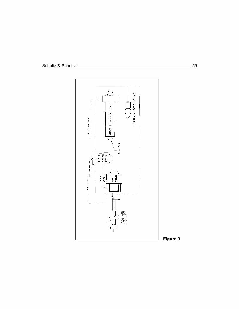
Wiring diagram for the incubator.
Figure 9
56 Mechanical Mom for Tarantulas
Continuing the Circuit
Figure 9 should be studied closely for this part of the project. Connect one of themeter long, sixteen gauge wires from the duplex outlet to one of the power poles orwires from the dimmer switch.
Connect one of the wires from the thermostat to the remaining pole or wire from thedimmer switch.
Connect the other power cord wire from the thermostat to one of the wires from thecandelabra socket.
Connect the remaining wire from the candelabra socket to the remaining meterlong, sixteen gauge wire from the duplex outlet on the other end of the baseboard.
Thus, we have constructed a complete loop of conducting wires from the powercord to the duplex outlet/timer switch to the dimmer switch, to the thermostat(modified aquarium heater) to the heater (modified candelabra socket) and back tothe duplex outlet/timer switch and power cord. Because the electric current musttravel through each part of this loop sequentially without missing any given part,they are said to be wired in a series.
Grounding
This series of steps is extremely important in the safe construction and operationof the incubator. For safety's sake, the builder is advised in the strongest possibleterms not to ignore grounding all the electrical parts of the incubator.
Connect another meter long, sixteen gauge wire from the grounding screw of theinitial duplex box to a mounting screw in the dimmer switch's duplex box. NorthAmerican electrical code requires this wire to be green in color. Connect anadditional, short jumper from the dimmer switch's grounding screw, if present, to thesame screw.
Schultz & Schultz 57
If the thermostat (aquarium heater) was equipped with a third wire ground, this mustbe connected to the grounding screw in the duplex box of either the duplexoutlet/timer switch or the dimmer switch.
At each connection, the excess length of wire may be trimmed off, leaving onlyenough to allow safe and secure connections, and to allow the conductors to lie outof harm's way. All wires should be fastened to the surface of the baseboard toeliminate the possibility of accidentally loosening the connections. If small staplesare used, extreme care must be exercised not to drive a leg of the staple throughthe conducting wire!

58 Mechanical Mom for Tarantulas
We encourage you to use the blank spaces in this booklet for your own notes.
Chapter 11: How It Works
In this configuration, the aquarium heater's purpose has been subverted and wenow call it merely the thermostat. We have substituted a low wattage candelabrabulb (that we call the heater) in place of the high wattage heating element becausethe heating element produced heat that was too intense.
The thermostat will determine when the bulb will be on or off, based on the actualtemperature of the inner enclosure. It will, therefore, determine the final temperatureof the inner enclosure.
The dimmer switch will control the current delivered to the bulb, and thereby, itsoperating temperature. If the heat is too intense, it can damage neighboring partsof the incubator, including the eggsacs, as well as shorten the life expectancy of thebulb. If the electric current is diminished, somewhat less heat will be produced. Thebulb will stay on longer but run slightly cooler, extending the bulb's service life andprotecting the other parts of the incubator and the eggsacs from heat damage.
While the dimmer switch controls the operating temperature of the heater, it hasabsolutely no effect on the temperature of the incubator as a whole.
The thermostat, a dimmer switch and the heater are now wired in a loop or series.For electric current to pass through any part of the loop, it must pass through EVERY
part of the loop. If one part fails, no current will flow. This basic concept is key tounderstanding the basis for the troubleshooting suggestions on page 69.

60 Mechanical Mom for Tarantulas
We encourage you to use the blank spaces in this booklet for your own notes.
Chapter 12: Hygrometer Assembly
Theory
The relative humidity (often called simply "humidity") of a sample of air is theamount of water that it actually holds, compared to the maximum amount of waterit could hold at that temperature, expressed as a percent of relative humidity or Rh.This value is highly temperature dependent.
A wet bulb-dry bulb hygrometer is an instrument used to measure the relativehumidity of a sample of air. Basically, it is composed of two accurate thermometers.One is kept dry and measures true air temperature, the other is kept moist and iscooled by the evaporating water.
The rate at which this water evaporates depends on the difficulty that the waterexperiences in leaving its liquid state and mixing as a vapor with the surrounding air.If the air is very dry, the water evaporates from the wet bulb thermometer rapidly,causing a significant cooling or depression in temperature. If the air is very wet, thewater will not evaporate as fast, and the temperature of the wet bulb thermometerwill not be depressed as much.
Therefore, the difference in the temperatures of the two thermometers is aconvenient indicator of the dryness or wetness of the air around them. Tables havebeen drawn up that correlate the dry bulb temperature and the temperature
Since the following passage was written several moderately accurate electronicrelative humidity gauges (hygrometers) have appeared on the market atreasonable prices. For convenience's sake, the enthusiast may wish to use oneof these instead of the wet bulb/dry bulb hygrometer described here.
Merely examine the entire lot that is on display and choose the one displaying avalue closest to the average Rh.
62 Mechanical Mom for Tarantulas
depression to the relative humidity of a sample of air. Relative humidity tables areavailable from many sources, such as weather bureaus, libraries, and schoolscience departments. One such table is presented on the inside of the front cover.
The hygrometer described here is only approximately accurate for a number ofreasons. But, because the conditions in the incubator are relatively static, the actualrelative humidity should not be significantly different from that which is indicated.
Thermometers
There are some rather rigid requirements for choosing the thermometers for thehygrometer, and installing them in the incubator.
The thermometers should be of the old fashioned red alcohol variety. While they willwork, mercury thermometers should be avoided whenever possible unless there issome compelling reason for using them. If they break, the mercury poses asignificant health and environmental hazard. The preferred type are standard, glass,aquarium thermometers.
Fever (medicinal) thermometers will not work. They usually are not sensitive in thepreferred temperature range, and they are built to register the highest temperaturesince they were last reset, not necessarily the current temperature. They must bereset after each reading.
Neither are the newer, liquid crystal thermometers suitable. It is difficult to determinethe exact temperature with these because there is no clear demarcation or line atwhich to read the temperature. Instead, there is a gradual color change over severaldegrees, introducing a potential for a substantial error. Also, it is difficult toimprovise a method whereby the thermometer could be efficiently cooled byevaporating water, and still allow for reading the temperature.
For the purposes of discussion we will use standard, glass, floating, aquariumthermometers from the neighborhood aquarium shop. Before purchasing thethermometers, compare all of those in stock. Choose two that read exactly the
Schultz & Schultz 63
same temperature, and that read closest to the average for the group. Whenchoosing the thermometers, do not handle them by the bulb. The heat of yourfingers will change the temperature they report, invalidating any further temperaturecomparisons. We will assume that these thermometers are reasonably accurate.If there is any question, they should be compared to calibrated laboratorythermometers in a school or college chemistry or physics laboratory or merelyreplaced with more trustworthy ones from the pet shop.
Installation
The position and orientation of the hygrometer thermometers is very important.They should be placed on the opposite end of the inner enclosure from the heater.This is to minimize the effects of the radiant heat from the heater.
Both thermometer bulbs should be at the same height in the inner enclosure. Thisis to minimize the stratifying effects of the warm air. Because warm air tends to rise,the warmer air will settle to the top of the enclosure, the cooler air to the bottom.Therefore, the higher thermometer would report a higher temperature than thelower, apart from the effects of evaporation, indicating an incorrect relative humidity.
The thermometer bulbs should be mounted very close to each other, ideally lessthan two centimeters (three-quarters inch) apart. The thermometers should bemounted so that the bulb of the wet bulb thermometer is suspended within onecentimeter (one-half inch) of the top of the humidifier dish. The thermometersshould be mounted so that their bulbs are at least twenty five millimeters (one inch)from the nearest wall of the inner enclosure to avoid temperature perturbationscaused by the relatively cool wall.
Lastly, they should be oriented in such a position that they may both be read easilythrough the incubator's front, without craning one's neck or opening the primary orinner enclosures.
MELTING HOLES is discussed in detail on page 30.
64 Mechanical Mom for Tarantulas
Silicone aquarium sealant can be cut away with a sharp knife, scalpel or3
razor blade if the thermometers must ever be replaced.
Put the humidifier dish in the inner enclosure, nearest the front side of the incubator,and farthest from the heater. Install the inner enclosure's cover. Estimate theposition of the holes for the two aquarium thermometers so that at least one isabove the humidifier dish. Drill or melt these holes in the inner enclosure’s lid.
Use silicone aquarium sealant to fasten the thermometers in the holes in the lid so3
that their bulbs are both at the same height in the inner enclosure, at least theminimum distance from the nearest wall, and the proper distance above the top ofthe humidifier dish.
In our example, the inner enclosure was too tall and the thermometers weremounted in an extra block of wood and suspended from the lid.
If necessary, some method should be used to tape, clamp, or prop thethermometers in their proper position while the bonding agent sets. Be cautious notto break the thermometers!
The dry bulb thermometer is used as it is. The wet bulb thermometer should havea small sleeve of cloth (e.g., a piece of polyester handkerchief or a section of abroad, nylon shoelace) tied to cover its bulb with the other end placed in thehumidifier dish. This will act as a wick to keep the end of the thermometer moist andcool. It is important that the cloth sleeve is made of a synthetic fabric. Cotton, linen,and wool will support mold and bacterial growths, endangering the eggsacs andsoon disintegrating. At first, make this sleeve ten centimeters (four inches) long.
Schultz & Schultz 65
Application
To determine relative humidity, one notes the dry bulb temperature and theDIFFERENCE between the wet and dry bulb temperatures (as opposed to the wet bulbtemperature alone). Consulting a relative humidity table (see the inside of the frontcover), locate the row headed by the dry bulb temperature and read across to thecolumn headed by the temperature difference. The number at the intersection is therelative humidity expressed as a percentage.
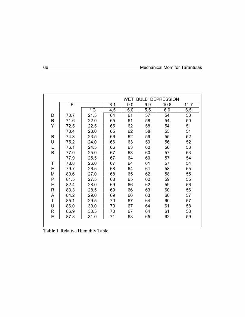
66 Mechanical Mom for Tarantulas
WET BULB DEPRESSIONE F 8.1 9.0 9.9 10.8 11.7
E C 4.5 5.0 5.5 6.0 6.5D 70.7 21.5 64 61 57 54 50R 71.6 22.0 65 61 58 54 50Y 72.5 22.5 65 62 58 54 51
73.4 23.0 65 62 58 55 51B 74.3 23.5 66 62 59 55 52U 75.2 24.0 66 63 59 56 52L 76.1 24.5 66 63 60 56 53B 77.0 25.0 67 63 60 57 53
77.9 25.5 67 64 60 57 54T 78.8 26.0 67 64 61 57 54E 79.7 26.5 68 64 61 58 55M 80.6 27.0 68 65 62 58 55P 81.5 27.5 68 65 62 59 55E 82.4 28.0 69 66 62 59 56R 83.3 28.5 69 66 63 60 56A 84.2 29.0 69 66 63 60 57T 85.1 29.5 70 67 64 60 57U 86.0 30.0 70 67 64 61 58R 86.9 30.5 70 67 64 61 58E 87.8 31.0 71 68 65 62 59
Table I Relative Humidity Table.
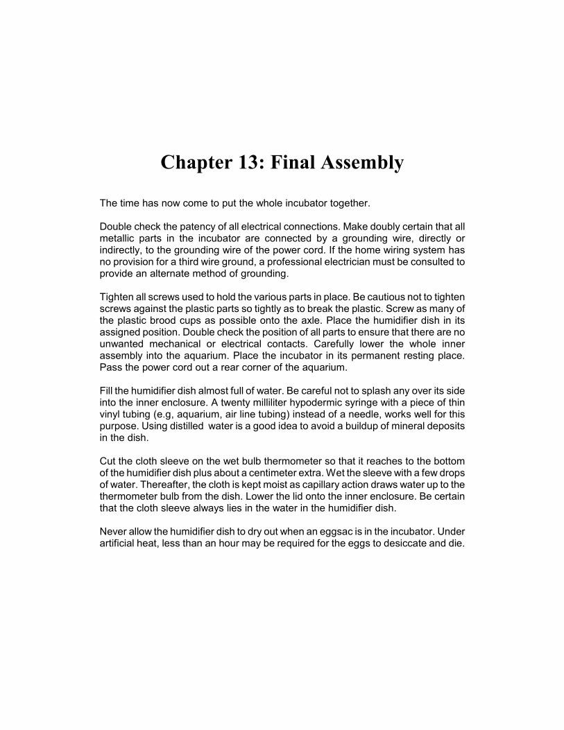
Chapter 13: Final Assembly
The time has now come to put the whole incubator together.
Double check the patency of all electrical connections. Make doubly certain that allmetallic parts in the incubator are connected by a grounding wire, directly orindirectly, to the grounding wire of the power cord. If the home wiring system hasno provision for a third wire ground, a professional electrician must be consulted toprovide an alternate method of grounding.
Tighten all screws used to hold the various parts in place. Be cautious not to tightenscrews against the plastic parts so tightly as to break the plastic. Screw as many ofthe plastic brood cups as possible onto the axle. Place the humidifier dish in itsassigned position. Double check the position of all parts to ensure that there are nounwanted mechanical or electrical contacts. Carefully lower the whole innerassembly into the aquarium. Place the incubator in its permanent resting place.Pass the power cord out a rear corner of the aquarium.
Fill the humidifier dish almost full of water. Be careful not to splash any over its sideinto the inner enclosure. A twenty milliliter hypodermic syringe with a piece of thinvinyl tubing (e.g, aquarium, air line tubing) instead of a needle, works well for thispurpose. Using distilled water is a good idea to avoid a buildup of mineral depositsin the dish.
Cut the cloth sleeve on the wet bulb thermometer so that it reaches to the bottomof the humidifier dish plus about a centimeter extra. Wet the sleeve with a few dropsof water. Thereafter, the cloth is kept moist as capillary action draws water up to thethermometer bulb from the dish. Lower the lid onto the inner enclosure. Be certainthat the cloth sleeve always lies in the water in the humidifier dish.
Never allow the humidifier dish to dry out when an eggsac is in the incubator. Underartificial heat, less than an hour may be required for the eggs to desiccate and die.

68 Mechanical Mom for Tarantulas
We encourage you to use the blank spaces in this booklet for your own notes.
Chapter 14: Loose Ends
Troubleshooting
Plug the incubator power cord into an electric outlet. Gently turn the knob on thethermostat. A small neon lamp will flicker on and off as a critical point is passed.The candelabra bulb should also go on and off with the neon lamp. The adjustmentto use for now is one where the neon lamp and candelabra bulb are on, but veryclose to turning off.
Following are some troubleshooting suggestions. For troubleshooting any of theelectrical parts, an ohmmeter or multimeter (combined volt, ohm, and amp meter)is an invaluable tool. Use the ohmmeter to check the electrical integrity of anysuspect portion of the circuit. All professional electricians possess them and theyare readily available from all hardware and electronics suppliers.
The thermostat's neon lamp fails to light altogether. First confirm that thepower cord is securely plugged into an outlet. Then confirm that the outlet haselectric power by plugging a table lamp or other appliance into it. Has a fuse orcircuit breaker been blown or tripped at the mains panel? If so, it was probably aresult of a fault in the incubator's circuitry. Do not replace the fuse or reset thecircuit breaker until you unplug the incubator.
DO NOT TOUCH THE INCUBATOR OR ANY OF ITS PARTS UNTIL YOU HAVEUNPLUGGED IT FROM ALL SOURCES OF POWER! Then, go over the incubator'scircuitry extremely carefully, comparing it closely with the diagram in Figure 9 todetermine where the fault lies. If you can not locate the fault do not plug theincubator back into the mains. Instead, take it to a professional electrician withthese instructions for service.
70 Mechanical Mom for Tarantulas
WARNING: TO AVOID POSSIBLY FATAL ELECTROCUTION, be absolutelycertain that the incubator has been unplugged from the electrical mains beforeopening any of the duplex boxes, or testing or manipulating any of the electricalconnections, or working with or near any exposed electrical conductors.
If electrical power is available to the incubator confirm that the dimmer switch isturned fully on. If the candelabra socket has an integral switch, be certain that it isturned on, as well. If the condition persists, try a different bulb, preferably one thatis proven good. If there is no change, double check the wiring. Are all theconnections sound? Are the circuits wired properly? If all else fails, disassemble andreconstruct the entire circuit a piece at a time, redoing each connection in turn. Ifthe incubator still does not work, replace each piece of equipment withindependently tested items.
The heater bulb remains on all the time. Either there is a serious fault in theincubator's circuitry or the thermostat is stuck or welded closed.
DO NOT TOUCH THE INCUBATOR OR ANY OF ITS PARTS UNTIL YOU HAVEUNPLUGGED IT FROM ALL SOURCES OF POWER! Then, follow the circuit pathof the electrical power through the incubator, comparing it to the diagram in Figure9 to confirm its patency. If that does not reveal an error in the circuitry, eitherreplace the thermostat entirely (strongly recommended) or disassemble it andcarefully inspect it to determine the problem and a solution.
Either the brood cups or the axle persistently comes unscrewed. Place afew drops of cyanoacrylate glue on the axle where it enters the loosening nut. Thiswill seal the thread so that the rod will not come undone. Doing this, however, willrequire breaking the nut off the timer or the brood cup lid and possibly replacing theentire assembly if the incubator must ever be dismantled for maintenance or repair.
Schultz & Schultz 71
Adjustments and Calibrations
Place the glass cover on the primary enclosure (aquarium), taking care to run thepower cord through a triangular corner cut. Allow the incubator's temperature tostabilize at least eight hours. If the temperature is too low, turn the thermostat'sadjustment knob approximately one-fourth turn clockwise. If the incubator is toowarm, turn the thermostat's knob approximately one-fourth turn anticlockwise(counterclockwise).
Then allow the incubator to equilibrate for several hours. Rreadjust as necessary.If the heater is not powerful enough to heat the incubator, replace the bulb with oneof higher wattage. After the temperature is properly adjusted, place a small pieceof tape across the adjustment knob on the thermostat's head to prevent itsaccidental misadjustment. You have now adjusted the thermostat and heater tomaintain a constant temperature in the incubator.
The dimmer switch should now be adjusted so that the heater is on one-third toone-half of the time when the surrounding room is at normal temperature. Thedimmer the bulb, the longer it will remain on. If the dimmer switch is turned to itsmaximum setting and the bulb remains on too long, replace the bulb with one of ahigher wattage rating. Note that this adjustment has absolutely no effect on theincubator's temperature, but rather only on the operating temperature of the heaterbulb. See page 21 for a discussion of this.
After the temperature is correct and stable, allow the incubator to set unopened forat least eight hours. Then determine the relative humidity by comparing the twothermometers. The wet bulb thermometer should report a lower temperature thanthe dry bulb thermometer after the system has reached equilibrium.
Humidity is maintained by simple evaporation. The humidifier dish must be keptfilled with water at all times. The wider the dish, the higher the relative humidity islikely to be, the deeper the dish the longer it will last before refilling is necessary.But, be cautious that this dish is not so wide or so deep as to interfere with theaction of the other mechanisms in the incubator, particularly the brood cups.
72 Mechanical Mom for Tarantulas
If the relative humidity is too low, cover one ventilation hole on each side of theinner enclosure with a bit of tape. After an additional several hours, if the relativehumidity is still too low, cover additional holes and allow the unit to equilibrate again.Leave at least six of the holes open (three towards the top and three on theopposite side towards the bottom). If the relative humidity is still too low, either awider humidifier dish may have to be substituted or a second dish may be placedin the inner enclosure to maintain a proper relative humidity.
Obviously, this calibration may take several days of experimenting. The prospectivetarantula breeder is strongly encouraged to build the incubator well in advance ofits expected use, get it up and running, and allow it to run indefinitely until required.While this may be viewed as a flagrant waste of electrical power, it must beremembered that the total power consumption of this incubator is less than 25watts. The expense of operating an empty incubator is minimal compared to thevalue of a successful hatch of tarantula babies.
Variations
Several variations have been suggested for this incubator. However, the authorshave not had an opportunity to test them. Those adventuresome enthusiasts whohave already made at least one working incubator and have successfully hatchedtarantula eggs, may want to try these variations or some of their own on a secondincubator.! An inner enclosure can be constructed from thin plywood, Perspex or
Plexiglas, gluing a piece of clear Perspex, Plexiglas or glass to the front toallow a clear view of the internal parts. Under any circumstances, it isimperative that at least the side of the container facing the front of theincubator be transparent to allow for easy reading of the thermometer scalesand visual inspection of the eggsacs.
! Use another insulated container in place of the aquarium. Possibilities includea Styrofoam picnic cooler, a custom built wooden case, or a small discardedrefrigerator (if a truly huge number of eggsacs is anticipated). If some othercontainer is chosen in place of an aquarium, an important consideration wouldbe the ability to install a transparent (Perspex, Plexiglas or glass) wall that
Schultz & Schultz 73
would allow reading the hygrometer and inspecting the eggsacs withoutopening the enclosure. If the enclosure is well insulated (e.g., a small uprightdeep freezer) a separate inner enclosure may not be necessary, but manyother changes in construction may have to be made to compensate for the lackof associated supporting structures.
! A candelabra bulb was used here because of limited space. With a slightlylarger inner enclosure, a standard household bulb socket and standard fifteenor twenty- five watt household bulb can be used. These will be easier toacquire and may be slightly less expensive. They pose no significantdifferences in wiring, placement or safety precautions. The larger size of thebulb does pose a problem with the amount of space required and itspositioning from the eggsacs to prevent their dessication. Be very certain thatthe outer envelope of the bulb is no closer to any part of the incubator than atleast twenty millimeters (three-quarters inch).
! Although the candelabra bulb will work, it throws intense heat directly at thebrood cups. There is the danger that this may bake the eggsac closest to theheater. If this appears to be a problem in the incubator, instead of using acandelabra bulb, use a common medicinal heating pad placed inside theprimary enclosure but under the baseboard. Before attempting this, comparethe wattage rating of the dimmer switch with that of the heating pad. Do notproceed unless the dimmer switch is able to accommodate the current loadimposed by the heating pad.
Cut the power cord of the heating pad and wire it into the circuit loop in place of theheater (candelabra socket/lamp). Many, if not most, heating pads have a three levelswitch for temperature adjustment. When cutting the cord for installation, the cutmust be made between the wall plug and the three level switch, NOT between theswitch and the heating pad. Seek the help of a professional electrician if this is notpatently clear to you.
After installation, start on the lowest heat level and wait for eight hours. If thetemperature does not stabilize at the appropriate level, move the heating pad switchto the next setting. As with the heater, the heating pad should be functionalapproximately one-third of the time. Most heating pads have a small neon lamp in
74 Mechanical Mom for Tarantulas
the switch to indicate when they are on, but this may not work because of thedimmer switch. Watch the thermometer closely instead.
Set the whole incubator on a board to protect the table or shelf underneath. Theheat from the heating pad can ruin the finish of the table on which it sets.! If an adequate temperature in the incubator cannot be maintained because the
unit is too large or the room around it is too cold, try clothing it with Styrofoaminsulation. This is available from most building supply dealers. Cover all sides,including top and bottom. If a heating pad is used, be certain to put a boardUNDER the aquarium, ABOVE the Styrofoam. If the Styrofoam becomes too hot,it will release poisonous fumes and could result in a fire.
Use tape to attach the Styrofoam to the sides and top of the incubator. Make someprovision to allow easy removal of the lid and front piece of Styrofoam withoutdismantling the rest of the insulation during daily inspections.! Use a commercial thermostat of the type used to control home heating plants
(furnaces) instead of the aquarium heater/thermostat. Most such thermostatsuse twelve or twenty four volt electric power and will not work in thisapplication. Make certain that the prospective unit is rated for the local mainsvoltage (nominally 120 volts in North America).
! Use a commercial, electronic humidity gauge. These are now becominginexpensive enough that they may be economically used in place of the wetbulb-dry bulb hygrometer described here. They are also becoming moreaccurate. Do not trust mechanical (non-electronic) humidity gauges unlessthey can be calibrated against a known, accurate standard. Seek help for thisfrom a school or college physics teacher or someone from the local weatherbureau, or a heating/air conditioning/ventilation (HVAC) contractor.
Schultz & Schultz 75
Day To Day Operation
Humidity Requirements. Continuing experience with these incubators hasshown that 60% Rh is the minimum allowable to ensure that an eggsac will notdessicate and the eggs die. However, contrary to prior "wisdom," it appears that theeggs will develop nicely at an Rh all the way up to 100% unless the silken eggsacitself becomes wet.
Whenever the incubator is opened, refill the humidifier dish. Use distilled water, ifat all possible, to avoid a mineral build up.
Temperature Requirements. Continuing experience also indicates that theeggs will develop without incident at any temperature between about 75E and 90EF (24E and 32E C), although 80E F (26.7E C) seems to be a good compromise. Atlower temperatures they will take longer to emerge from the eggsac and at highertemperatures they will tend to emerge sooner.
Eggsac Maintenance. Because arrangements have been made for more thanone brood cup to be used at a time, it is possible to incubate more than one eggsacat a time. The exact number will depend on the size of the eggsacs, the size of thecups, and the size of the inner enclosure.
Once an eggsac is incubating, rotate the brood cup a full 360 degrees or more byhand at least once a day. This affords an added jostling to the eggs, and helpsbreak up any clumping in the eggsac. With most timers, this may mean only rotatingthe dial by hand. With a clock motor assembly or some timers, this may requiremanually unscrewing and rescrewing the brood cups.
Mark each brood cup with a felt tipped marker so that you can always tell at aglance that it has rotated an appropriate amount since the last inspection.
Each eggsac should be able to roll freely in its brood cup without being wedgedbetween the ends. If an eggsac is small enough to do this in only one brood cup,
76 Mechanical Mom for Tarantulas
no alterations need be made. However, the eggsacs made by the larger femalesmay be too large for a single brood cup. In that case, carefully remove the floor ofa second brood cup, leaving only the cylindrical wall. Use a coping saw with a veryfine toothed blade. Lubricate the saw blade with liquid dish detergent or salad oil.Work slowly and carefully. File away the coarsest burrs, first with a coarse and thena medium rat tail file, to produce a relatively smooth plastic cylinder. Be verycautious not to damage the threads. Thread the cylinder onto another brood cup toform a chamber twice the regular length. Now, place the large eggsac in this doublebrood cup.
A little roughness on the inside is desirable, catching the silken eggsac and turningit. Without some roughness, a heavy eggsac might merely slide along the insidewall. If this happens, a simple cylinder of a coarse mesh nylon fabric (available froma fabric store) can be inserted against the inner wall of each cup to increase frictionfor the eggsac. If it slides as well, tack it in place with one or two drops ofcyanoacrylate glue.
Record Keeping. Be certain to record the parentage and dates of each eggsacin some completely unambiguous fashion. Keep accurate records for each one todetermine appropriate hatching dates, and to track pedigrees for future generations.
Schultz and Schultz (1998) presents data on incubation times for a variety ofspecies.
Remarks
The construction and initial set up of this incubator will require considerable workand time. It is obviously not a project to be assumed without some forethought andplanning. Neither is it likely to be a casual weekend project. This will undoubtedlydissuade some enthusiasts from making one.
If the trouble and expense required to breed a pair of tarantulas, the rewards fromthe satisfaction of accomplishing the feat, and the monetary benefits from sellingthe babies are considered, the time and effort required to construct the incubator

Schultz & Schultz 77
is actually quite small. And, once it is made it will likely last for years. It's all part ofthe fun of keeping and breeding pet tarantulas.

78 Mechanical Mom for Tarantulas
We encourage you to use the blank spaces in this booklet for your own notes.
Bibliography
Baerg, W. J. 1928. The life cycle and mating habits of the male tarantula. Quart.Review Biol. 3(1):109-116.
1958. The Tarantula. Univ. Kansas Press. Lawrence. (Father oftarantula books. Now available as a reprint: Fitzgerald Publishing. London, UKand El Cerito, California.).
Barnes, R. D. 1980. Invertebrate Zoology. Saunders College/Holt Reinhart andWinston. Philadelphia, Pennsylvania.
Baxter, R. N. 1993. Keeping and Breeding Tarantulas. Chudleigh Publishing. Ilford,Essex, England. (Excellent photography. One of the better enthusiast books.)
Breene, R. G. 2005. Quick & Easy Tarantula Care. TFH Publications, Inc. NeptuneCity, NJ.
David, A. 1987. Tarantulas. A Complete Introduction. T.F.H. Publications. NeptuneCity, New Jersey.
de Vosjoli, P. 1991. Arachnomania. The General Care and Maintenance ofTarantulas & Scorpions. Advanced Aquarium Systems. Lakeside, California.
Downes, M. F. 1987. A proposal for standardization of the terms used to describethe early development of spiders, based on a study of Theridion rufipes Lucas(Araneae: Theridiidae). Bull. British Arachnol. Soc. 7:187-193.
Foelix, R. F. 1982. Biology of Spiders. Harvard University Press. Cambridge,Massachusetts. (English edition.)
Hancock, K. and J. Hancock. 1992. Tarantulas: Keeping and Breeding Arachnidsin Captivity. R & A Publishing, Limited. Somerset, England.
80 Mechanical Mom for Tarantulas
Lund, D. 1977. All About Tarantulas. T.F.H. Publications. Neptune City, NewJersey.
Marshall, S. 1966 Tarantulas and Other Arachnids. Barron's. Hauppauge, NY.(Highly recommended. One of the best books on the market.)
McKee, A. W. 1984a. Tarantula Observations, A Guide to Breeding. Vol. 1.Tarantula Ranch Press. Kenmore, Washington, USA.
1984b. Tarantula Observations, A Guide to Breeding. Vol. II.Tarantula Ranch Press. Kenmore, Washington, USA.
1986. Tarantula Observations, A Guide to Breeding. Vol. 3. BreedersDigest. Tarantula Ranch Press. Kenmore, Washington, USA.
Meglitch, P. A. 1972. Invertebrate Zoology, Second Edition. Oxford UniversityPress. New York.
Minch, E. W. 1979. Reproductive behavior of the tarantula Aphonopelma chalcodesChamberlin (Araneae: Theraphosidae). Bull. Br. Arachnol. Soc. 4(9):416-420.
Perrero, L. and L. Perrero. 1979. Tarantulas in Nature and as Pets. WindwardPublishing. Miami, Florida.
Schultz, S. A. 1984. The Tarantula Keeper's Guide. Sterling Publishing. New York.
Schultz, S. A. and M. J. Schultz. 1998. The Tarantula Keeper's Guide, SecondEdition. Barron's Educational Series. Hauppauge, NY. (A sweeping revision ofthe former work.)
Schultz, S. A. and M. J. Schultz. 2009. The Tarantula Keeper's Guide, Third Edition.Barron's Educational Series. Hauppauge, NY.

Schultz & Schultz 81
Smith, A. M. 1986. How to Keep Tarantulas. Fitzgerald Publishing. London,England.
Turbang, P. 1993. Guide de Mygales. Delachaux et Niestlé. Lausanne, Switzerland.
Webb, A. 1992. The Proper Care of Tarantulas. T.F.H. Publications. Neptune City,New Jersey.

82 Mechanical Mom for Tarantulas
We encourage you to use the blank spaces in this booklet for your own notes.
Index
Acetone.. . . . . . . . . . . . . . . . . . . . . . . . . . . . . . . . . . . . . . . . . . . . . . . . . . . 25, 27Acrylic
fishing tackle boxes. . . . . . . . . . . . . . . . . . . . . . . . . . . . . . . . . . . . . . . . . . 33plastic (see also Plexiglas and Perspex). . . . . . . . . . . . . . . . . . . . . . . 18, 25
Adhesives. . . . . . . . . . . . . . . . . . . . . . . . . . . . . . . . . . . . . . . . . . . . . . . 28, 44, 48epoxy glue.. . . . . . . . . . . . . . . . . . . . . . . . . . . . . . . . . . . . . . . . . . . . . . . . 13PVC plumbing cement.. . . . . . . . . . . . . . . . . . . . . . . . . . . . . . . . . . . . . . . 13silicone rubber. . . . . . . . . . . . . . . . . . . . . . . . . . . . . . . . . . . . . . . . . . . 13, 45
Aircool. . . . . . . . . . . . . . . . . . . . . . . . . . . . . . . . . . . . . . . . . . . . . . . . 18, 45, 48layered/stratified. . . . . . . . . . . . . . . . . . . . . . . . . . . . . . . . . . . . . . 47, 48, 63line tubing. . . . . . . . . . . . . . . . . . . . . . . . . . . . . . . . . . . . . . . . . . . . . . . . . 67relative humidity. . . . . . . . . . . . . . . . . . . . . . . . . . . . . . . . . . . . . . . . . 61, 62temperature.. . . . . . . . . . . . . . . . . . . . . . . . . . . . . . . . . . . . . . . . . . . . . . . 61warm. . . . . . . . . . . . . . . . . . . . . . . . . . . . . . . . . . . . . . . . . . . . . . . 47, 48, 63
Alcoholcleaning.. . . . . . . . . . . . . . . . . . . . . . . . . . . . . . . . . . . . . . 13, 24, 25, 27, 39thermometers. . . . . . . . . . . . . . . . . . . . . . . . . . . . . . . . . . . . . . . . . . . . . . 62
Aquariumcover/lid.. . . . . . . . . . . . . . . . . . . . . . . . . . . . . . . . . . . . . . . . . . . . 13, 17, 29heater. . . . . . . . . . . . . . . . . . . viii, 14, 23, 29, 31, 41, 42, 47, 56, 57, 59, 74incubator containment housing. . . . . . . . . . . . . . . . . . . . . . . . . . . . . . . . . viiinner enclosure. . . . . . . . . . . . . . . . . . . . . . . . . . . . . . . . . . . . . . . . . . 29, 30primary enclosure. . . . . . . . . . . . . . vii, viii, 13, 17, 21, 29, 43, 67, 71, 72, 74sealer, silicone rubber. . . . . . . . . . . . . . . . . . . . . . . . . . . . 13, 39, 45, 48, 64thermometers. . . . . . . . . . . . . . . . . . . . . . . . . . . . . . . . . . . . . viii, 15, 62, 64
Assemblyclock motor. . . . . . . . . . . . . . . . . . . . . . . . . 13, 21, 27, 28, 35-40, 53, 54, 75duplex box. . . . . . . . . . . . . . . . . . . . . . . . . . . . . . . . . . . . . . . . . . . . . . . . . 37duplex outlet. . . . . . . . . . . . . . . . . . . . . . . . . . . . . . . . . . . . . . . . . . . . . . . 37final. . . . . . . . . . . . . . . . . . . . . . . . . . . . . . . . . . . . . . . . . . . . . . . . . . . . . . 67
84 Mechanical Mom for Tarantulas
heater. . . . . . . . . . . . . . . . . . . . . . . . . . . . . . . . . . . . . . . . . . . . . . . . . 47, 48hygrometer. . . . . . . . . . . . . . . . . . . . . . . . . . . . . . . . . . . . . . . . . . . . . . . . 61inner (baseboard & inner encl.. . . . . . . . . . . . . . . . . . . . . . . . . . . . . . 43, 67thermostat. . . . . . . . . . . . . . . . . . . . . . . . . . . . . . . . . . . . . . . . . . . . . . 41, 45timer switch. . . . . . . . . . . . . . . . . . . . . . . . . . . . . . . . . . . . . . . 24, 36, 37, 40
Axle.. . . . . . . . . . . . . . . . . . . . . . . . . . . . . . . . . . vii, viii, 14, 24, 28, 35-40, 67, 70hole. . . . . . . . . . . . . . . . . . . . . . . . . . . . . . . . . . . . . . . . . . . 33, 35-37, 39, 40
Babies, tarantula. . . . . . . . . . . . . . . . . . . . . . . . . . . . . . . . . . . . . . . . . . . . . 72, 76Bacterial growths. . . . . . . . . . . . . . . . . . . . . . . . . . . . . . . . . . . . . . . . . . . . . . . 64Baseboard. . . . . . . . . . . . . . 13, 21, 22, 24, 29, 32, 36-39, 51, 53, 54, 56, 57, 73Bathtub sealer.. . . . . . . . . . . . . . . . . . . . . . . . . . . . . . . . . . . . . . . . . . . . . . . . . 14Benefits, monetary. . . . . . . . . . . . . . . . . . . . . . . . . . . . . . . . . . . . . . . . . . . . . . 76Bits
drill. . . . . . . . . . . . . . . . . . . . . . . . . . . . . . . . . . . . . . . . . . . . . . . . . . . . . . 30tape. . . . . . . . . . . . . . . . . . . . . . . . . . . . . . . . . . . . . . . . . . . . . . . . . . . . . . 72
Bladerazor. . . . . . . . . . . . . . . . . . . . . . . . . . . . . . . . . . . . . . . . . . . . . . . . . . 45, 64saw. . . . . . . . . . . . . . . . . . . . . . . . . . . . . . . . . . . . . . . . . . . . . . . . . . . . . . 76
Blind plate (see also duplex box cover). . . . . . . . . . . . . . . . . . . . . . . . . 13, 28, 38Board (see also baseboard). . . . . . . . . . . . . . . . . . . . . . . . . . . vii, 13, 18, 44, 74Box
cover. . . . . . . . . . . . . . . . . . . . . . . . . . . . . . . . . . . . . . . . . . . . . . . . . . 13, 38duplex electrical.. . . . . . . . . . . . . . . 13, 21-24, 28, 29, 37, 38, 53, 54, 56, 57electric mains. . . . . . . . . . . . . . . . . . . . . . . . . . . . . . . . . . . . . . . . . . . . . . 23fishing tackle. . . . . . . . . . . . . . . . . . . . . . . . . . . . . . . . . . . . . . . . . . . . . ix, 33inner enclosure. . . . . . . . . . . . . . . . . . . . . . . . . . . . . . . . . . . . . . . vii, 13, 30plastic (see also Plexiglas and Perspex). . . . . . . . . . . . . . . vii, ix, 13, 30, 33
Brass tubes. . . . . . . . . . . . . . . . . . . . . . . . . . . . . . . . . . . . . . . . . . . . . . . . . . . . 28Breaker, circuit. . . . . . . . . . . . . . . . . . . . . . . . . . . . . . . . . . . . . . . . . . . . . . . . . 69Bridge, timer dial. . . . . . . . . . . . . . . . . . . . . . . . . . . . . . . . . . . . . . . . . . . . . 24, 27Brood cups (see also fishing tackle boxes). . . . 14, 33, 35-37, 40, 43, 48, 67, 70,
71, 73, 75, 76Bulb
candelabra (see also night-light). . . . . . . . viii, 14, 31, 42, 47, 48, 59, 69, 73
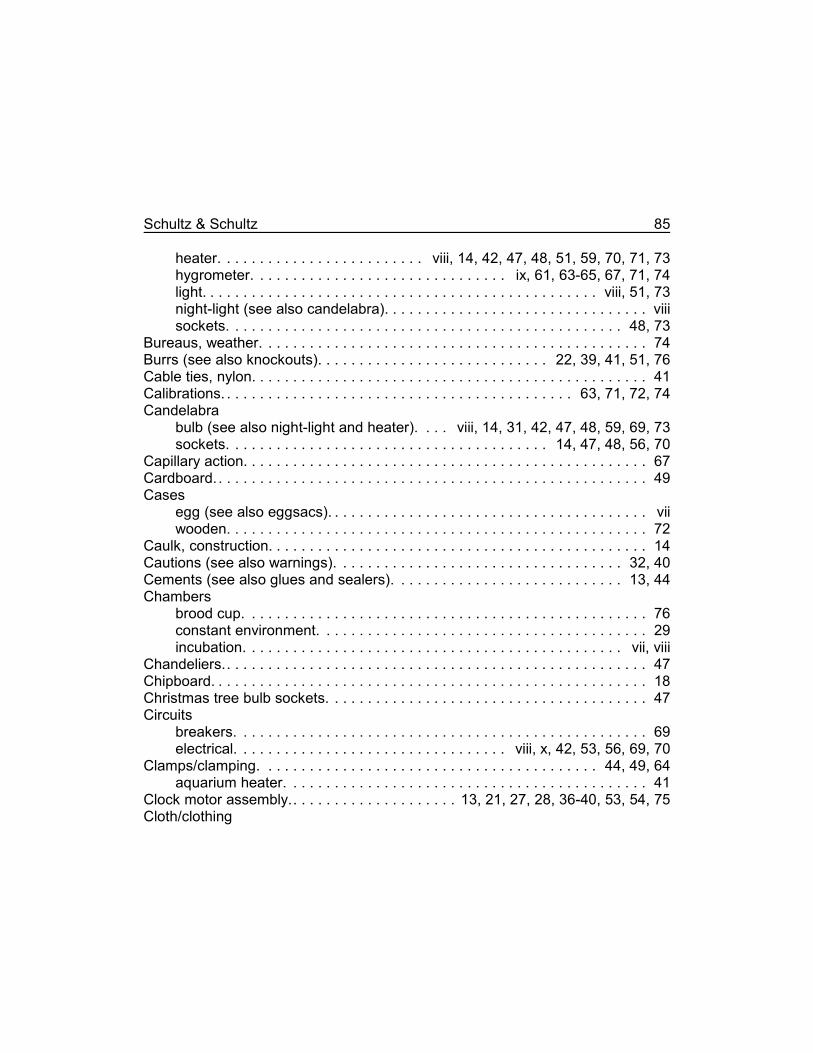
Schultz & Schultz 85
heater. . . . . . . . . . . . . . . . . . . . . . . . . viii, 14, 42, 47, 48, 51, 59, 70, 71, 73hygrometer. . . . . . . . . . . . . . . . . . . . . . . . . . . . . . . ix, 61, 63-65, 67, 71, 74light. . . . . . . . . . . . . . . . . . . . . . . . . . . . . . . . . . . . . . . . . . . . . . . . viii, 51, 73night-light (see also candelabra). . . . . . . . . . . . . . . . . . . . . . . . . . . . . . . . viiisockets. . . . . . . . . . . . . . . . . . . . . . . . . . . . . . . . . . . . . . . . . . . . . . . . 48, 73
Bureaus, weather. . . . . . . . . . . . . . . . . . . . . . . . . . . . . . . . . . . . . . . . . . . . . . . 74Burrs (see also knockouts). . . . . . . . . . . . . . . . . . . . . . . . . . . . 22, 39, 41, 51, 76Cable ties, nylon. . . . . . . . . . . . . . . . . . . . . . . . . . . . . . . . . . . . . . . . . . . . . . . . 41Calibrations. . . . . . . . . . . . . . . . . . . . . . . . . . . . . . . . . . . . . . . . . . . 63, 71, 72, 74Candelabra
bulb (see also night-light and heater). . . . viii, 14, 31, 42, 47, 48, 59, 69, 73sockets. . . . . . . . . . . . . . . . . . . . . . . . . . . . . . . . . . . . . . . 14, 47, 48, 56, 70
Capillary action. . . . . . . . . . . . . . . . . . . . . . . . . . . . . . . . . . . . . . . . . . . . . . . . . 67Cardboard. . . . . . . . . . . . . . . . . . . . . . . . . . . . . . . . . . . . . . . . . . . . . . . . . . . . . 49Cases
egg (see also eggsacs). . . . . . . . . . . . . . . . . . . . . . . . . . . . . . . . . . . . . . . viiwooden. . . . . . . . . . . . . . . . . . . . . . . . . . . . . . . . . . . . . . . . . . . . . . . . . . . 72
Caulk, construction. . . . . . . . . . . . . . . . . . . . . . . . . . . . . . . . . . . . . . . . . . . . . . 14Cautions (see also warnings). . . . . . . . . . . . . . . . . . . . . . . . . . . . . . . . . . . 32, 40Cements (see also glues and sealers). . . . . . . . . . . . . . . . . . . . . . . . . . . . 13, 44Chambers
brood cup. . . . . . . . . . . . . . . . . . . . . . . . . . . . . . . . . . . . . . . . . . . . . . . . . 76constant environment. . . . . . . . . . . . . . . . . . . . . . . . . . . . . . . . . . . . . . . . 29incubation. . . . . . . . . . . . . . . . . . . . . . . . . . . . . . . . . . . . . . . . . . . . . . vii, viii
Chandeliers.. . . . . . . . . . . . . . . . . . . . . . . . . . . . . . . . . . . . . . . . . . . . . . . . . . . 47Chipboard. . . . . . . . . . . . . . . . . . . . . . . . . . . . . . . . . . . . . . . . . . . . . . . . . . . . . 18Christmas tree bulb sockets. . . . . . . . . . . . . . . . . . . . . . . . . . . . . . . . . . . . . . . 47Circuits
breakers. . . . . . . . . . . . . . . . . . . . . . . . . . . . . . . . . . . . . . . . . . . . . . . . . . 69electrical. . . . . . . . . . . . . . . . . . . . . . . . . . . . . . . . . viii, x, 42, 53, 56, 69, 70
Clamps/clamping. . . . . . . . . . . . . . . . . . . . . . . . . . . . . . . . . . . . . . . . . 44, 49, 64aquarium heater. . . . . . . . . . . . . . . . . . . . . . . . . . . . . . . . . . . . . . . . . . . . 41
Clock motor assembly.. . . . . . . . . . . . . . . . . . . . 13, 21, 27, 28, 36-40, 53, 54, 75Cloth/clothing
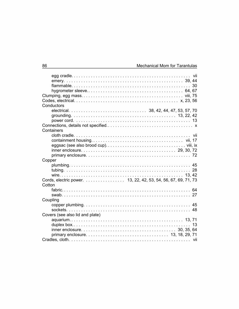
86 Mechanical Mom for Tarantulas
egg cradle. . . . . . . . . . . . . . . . . . . . . . . . . . . . . . . . . . . . . . . . . . . . . . . . . viiemery. . . . . . . . . . . . . . . . . . . . . . . . . . . . . . . . . . . . . . . . . . . . . . . . . 39, 44flammable. . . . . . . . . . . . . . . . . . . . . . . . . . . . . . . . . . . . . . . . . . . . . . . . . 30hygrometer sleeve.. . . . . . . . . . . . . . . . . . . . . . . . . . . . . . . . . . . . . . . 64, 67
Clumping, egg mass. . . . . . . . . . . . . . . . . . . . . . . . . . . . . . . . . . . . . . . . . . viii, 75Codes, electrical. . . . . . . . . . . . . . . . . . . . . . . . . . . . . . . . . . . . . . . . . . . x, 23, 56Conductors
electrical. . . . . . . . . . . . . . . . . . . . . . . . . . . . . . . . 38, 42, 44, 47, 53, 57, 70grounding. . . . . . . . . . . . . . . . . . . . . . . . . . . . . . . . . . . . . . . . . . . 13, 22, 42power cord. . . . . . . . . . . . . . . . . . . . . . . . . . . . . . . . . . . . . . . . . . . . . . . . 13
Connections, details not specified. . . . . . . . . . . . . . . . . . . . . . . . . . . . . . . . . . . . xContainers
cloth cradle. . . . . . . . . . . . . . . . . . . . . . . . . . . . . . . . . . . . . . . . . . . . . . . . viicontainment housing. . . . . . . . . . . . . . . . . . . . . . . . . . . . . . . . . . . . . . vii, 17eggsac (see also brood cup). . . . . . . . . . . . . . . . . . . . . . . . . . . . . . . . . viii, ixinner enclosure. . . . . . . . . . . . . . . . . . . . . . . . . . . . . . . . . . . . . . . 29, 30, 72primary enclosure. . . . . . . . . . . . . . . . . . . . . . . . . . . . . . . . . . . . . . . . . . . 72
Copperplumbing. . . . . . . . . . . . . . . . . . . . . . . . . . . . . . . . . . . . . . . . . . . . . . . . . . 45tubing. . . . . . . . . . . . . . . . . . . . . . . . . . . . . . . . . . . . . . . . . . . . . . . . . . . . 28wire. . . . . . . . . . . . . . . . . . . . . . . . . . . . . . . . . . . . . . . . . . . . . . . . . . . 13, 42
Cords, electric power. . . . . . . . . . . . . . . . . 13, 22, 42, 53, 54, 56, 67, 69, 71, 73Cotton
fabric. . . . . . . . . . . . . . . . . . . . . . . . . . . . . . . . . . . . . . . . . . . . . . . . . . . . . 64swab. . . . . . . . . . . . . . . . . . . . . . . . . . . . . . . . . . . . . . . . . . . . . . . . . . . . . 27
Couplingcopper plumbing. . . . . . . . . . . . . . . . . . . . . . . . . . . . . . . . . . . . . . . . . . . . 45sockets. . . . . . . . . . . . . . . . . . . . . . . . . . . . . . . . . . . . . . . . . . . . . . . . . . . 48
Covers (see also lid and plate)aquarium. . . . . . . . . . . . . . . . . . . . . . . . . . . . . . . . . . . . . . . . . . . . . . . 13, 71duplex box. . . . . . . . . . . . . . . . . . . . . . . . . . . . . . . . . . . . . . . . . . . . . . . . . 13inner enclosure. . . . . . . . . . . . . . . . . . . . . . . . . . . . . . . . . . . . . . . 30, 35, 64primary enclosure. . . . . . . . . . . . . . . . . . . . . . . . . . . . . . . . . . 13, 18, 29, 71
Cradles, cloth. . . . . . . . . . . . . . . . . . . . . . . . . . . . . . . . . . . . . . . . . . . . . . . . . . vii
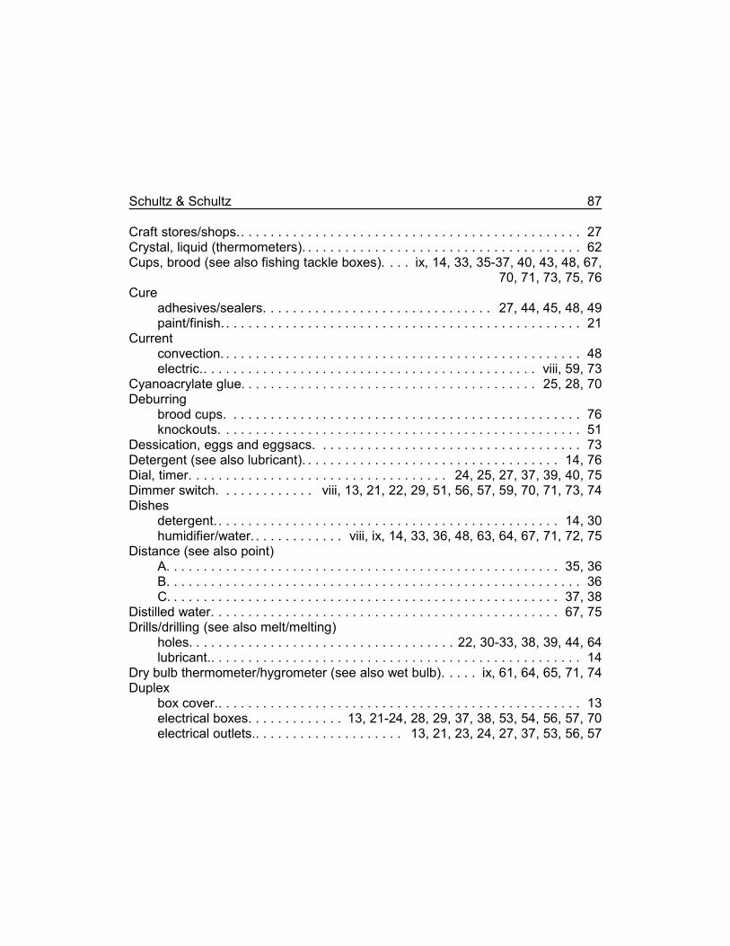
Schultz & Schultz 87
Craft stores/shops.. . . . . . . . . . . . . . . . . . . . . . . . . . . . . . . . . . . . . . . . . . . . . . 27Crystal, liquid (thermometers). . . . . . . . . . . . . . . . . . . . . . . . . . . . . . . . . . . . . . 62Cups, brood (see also fishing tackle boxes). . . . ix, 14, 33, 35-37, 40, 43, 48, 67,
70, 71, 73, 75, 76Cure
adhesives/sealers. . . . . . . . . . . . . . . . . . . . . . . . . . . . . . . 27, 44, 45, 48, 49paint/finish. . . . . . . . . . . . . . . . . . . . . . . . . . . . . . . . . . . . . . . . . . . . . . . . . 21
Currentconvection. . . . . . . . . . . . . . . . . . . . . . . . . . . . . . . . . . . . . . . . . . . . . . . . . 48electric.. . . . . . . . . . . . . . . . . . . . . . . . . . . . . . . . . . . . . . . . . . . . . viii, 59, 73
Cyanoacrylate glue. . . . . . . . . . . . . . . . . . . . . . . . . . . . . . . . . . . . . . . . 25, 28, 70Deburring
brood cups. . . . . . . . . . . . . . . . . . . . . . . . . . . . . . . . . . . . . . . . . . . . . . . . 76knockouts. . . . . . . . . . . . . . . . . . . . . . . . . . . . . . . . . . . . . . . . . . . . . . . . . 51
Dessication, eggs and eggsacs. . . . . . . . . . . . . . . . . . . . . . . . . . . . . . . . . . . . 73Detergent (see also lubricant). . . . . . . . . . . . . . . . . . . . . . . . . . . . . . . . . . . 14, 76Dial, timer. . . . . . . . . . . . . . . . . . . . . . . . . . . . . . . . . . . 24, 25, 27, 37, 39, 40, 75Dimmer switch. . . . . . . . . . . . . viii, 13, 21, 22, 29, 51, 56, 57, 59, 70, 71, 73, 74Dishes
detergent. . . . . . . . . . . . . . . . . . . . . . . . . . . . . . . . . . . . . . . . . . . . . . . 14, 30humidifier/water. . . . . . . . . . . . . viii, ix, 14, 33, 36, 48, 63, 64, 67, 71, 72, 75
Distance (see also point)A. . . . . . . . . . . . . . . . . . . . . . . . . . . . . . . . . . . . . . . . . . . . . . . . . . . . . 35, 36B. . . . . . . . . . . . . . . . . . . . . . . . . . . . . . . . . . . . . . . . . . . . . . . . . . . . . . . . 36C. . . . . . . . . . . . . . . . . . . . . . . . . . . . . . . . . . . . . . . . . . . . . . . . . . . . . 37, 38
Distilled water. . . . . . . . . . . . . . . . . . . . . . . . . . . . . . . . . . . . . . . . . . . . . . . 67, 75Drills/drilling (see also melt/melting)
holes. . . . . . . . . . . . . . . . . . . . . . . . . . . . . . . . . . . . 22, 30-33, 38, 39, 44, 64lubricant.. . . . . . . . . . . . . . . . . . . . . . . . . . . . . . . . . . . . . . . . . . . . . . . . . . 14
Dry bulb thermometer/hygrometer (see also wet bulb). . . . . ix, 61, 64, 65, 71, 74Duplex
box cover.. . . . . . . . . . . . . . . . . . . . . . . . . . . . . . . . . . . . . . . . . . . . . . . . . 13electrical boxes. . . . . . . . . . . . . 13, 21-24, 28, 29, 37, 38, 53, 54, 56, 57, 70electrical outlets.. . . . . . . . . . . . . . . . . . . . 13, 21, 23, 24, 27, 37, 53, 56, 57
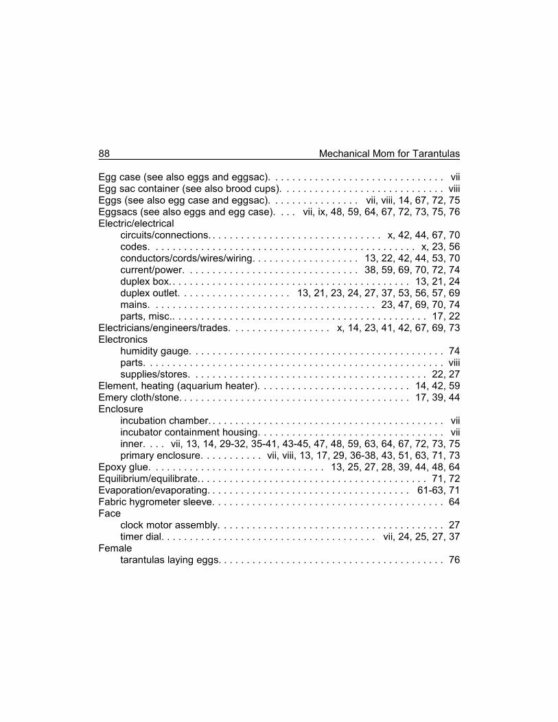
88 Mechanical Mom for Tarantulas
Egg case (see also eggs and eggsac). . . . . . . . . . . . . . . . . . . . . . . . . . . . . . . viiEgg sac container (see also brood cups). . . . . . . . . . . . . . . . . . . . . . . . . . . . . viiiEggs (see also egg case and eggsac). . . . . . . . . . . . . . . . vii, viii, 14, 67, 72, 75Eggsacs (see also eggs and egg case). . . . vii, ix, 48, 59, 64, 67, 72, 73, 75, 76Electric/electrical
circuits/connections. . . . . . . . . . . . . . . . . . . . . . . . . . . . . . . x, 42, 44, 67, 70codes. . . . . . . . . . . . . . . . . . . . . . . . . . . . . . . . . . . . . . . . . . . . . . . x, 23, 56conductors/cords/wires/wiring. . . . . . . . . . . . . . . . . . . 13, 22, 42, 44, 53, 70current/power. . . . . . . . . . . . . . . . . . . . . . . . . . . . . . . 38, 59, 69, 70, 72, 74duplex box. . . . . . . . . . . . . . . . . . . . . . . . . . . . . . . . . . . . . . . . . . . 13, 21, 24duplex outlet. . . . . . . . . . . . . . . . . . . . 13, 21, 23, 24, 27, 37, 53, 56, 57, 69mains. . . . . . . . . . . . . . . . . . . . . . . . . . . . . . . . . . . . . . . . 23, 47, 69, 70, 74parts, misc.. . . . . . . . . . . . . . . . . . . . . . . . . . . . . . . . . . . . . . . . . . . . . 17, 22
Electricians/engineers/trades. . . . . . . . . . . . . . . . . . x, 14, 23, 41, 42, 67, 69, 73Electronics
humidity gauge. . . . . . . . . . . . . . . . . . . . . . . . . . . . . . . . . . . . . . . . . . . . . 74parts. . . . . . . . . . . . . . . . . . . . . . . . . . . . . . . . . . . . . . . . . . . . . . . . . . . . . viiisupplies/stores. . . . . . . . . . . . . . . . . . . . . . . . . . . . . . . . . . . . . . . . . . 22, 27
Element, heating (aquarium heater). . . . . . . . . . . . . . . . . . . . . . . . . . . 14, 42, 59Emery cloth/stone. . . . . . . . . . . . . . . . . . . . . . . . . . . . . . . . . . . . . . . . . 17, 39, 44Enclosure
incubation chamber. . . . . . . . . . . . . . . . . . . . . . . . . . . . . . . . . . . . . . . . . . viiincubator containment housing. . . . . . . . . . . . . . . . . . . . . . . . . . . . . . . . . viiinner. . . . vii, 13, 14, 29-32, 35-41, 43-45, 47, 48, 59, 63, 64, 67, 72, 73, 75primary enclosure. . . . . . . . . . . vii, viii, 13, 17, 29, 36-38, 43, 51, 63, 71, 73
Epoxy glue. . . . . . . . . . . . . . . . . . . . . . . . . . . . . . . 13, 25, 27, 28, 39, 44, 48, 64Equilibrium/equilibrate.. . . . . . . . . . . . . . . . . . . . . . . . . . . . . . . . . . . . . . . . 71, 72Evaporation/evaporating. . . . . . . . . . . . . . . . . . . . . . . . . . . . . . . . . . . . 61-63, 71Fabric hygrometer sleeve. . . . . . . . . . . . . . . . . . . . . . . . . . . . . . . . . . . . . . . . . 64Face
clock motor assembly. . . . . . . . . . . . . . . . . . . . . . . . . . . . . . . . . . . . . . . . 27timer dial. . . . . . . . . . . . . . . . . . . . . . . . . . . . . . . . . . . . . . vii, 24, 25, 27, 37
Femaletarantulas laying eggs. . . . . . . . . . . . . . . . . . . . . . . . . . . . . . . . . . . . . . . . 76
Schultz & Schultz 89
threading on brood cups. . . . . . . . . . . . . . . . . . . . . . . . . . . . . . . . . . . . . . 33Fever thermometers. . . . . . . . . . . . . . . . . . . . . . . . . . . . . . . . . . . . . . . . . . . . . 62Fiber board. . . . . . . . . . . . . . . . . . . . . . . . . . . . . . . . . . . . . . . . . . . . . . . . . . . . 18Files/filing. . . . . . . . . . . . . . . . . . . . . . . . . . . . . . . . . . . . . . . . . 22, 31, 39, 41, 76Finish (e.g., paint, varnish). . . . . . . . . . . . . . . . . . . . . . . . . . . . . . . . . . . . . 21, 74Fire danger. . . . . . . . . . . . . . . . . . . . . . . . . . . . . . . . . . . . . . . . . . . . . . . . . 30, 74Fire extinguisher. . . . . . . . . . . . . . . . . . . . . . . . . . . . . . . . . . . . . . . . . . . . . . . . 30Fishing tackle
boxes (see also brood cups). . . . . . . . . . . . . . . . . . . . . . . . . . . . . . . . . ix, 14supplies/stores. . . . . . . . . . . . . . . . . . . . . . . . . . . . . . . . . . . . . . . . . . . . . 33
Food container (incubation container). . . . . . . . . . . . . . . . . . . . . . . . . . . . . . . . 29Fostaty, Michael. . . . . . . . . . . . . . . . . . . . . . . . . . . . . . . . . . . . . . . . . . . . . . . . viiiFuse (see also circuit breaker). . . . . . . . . . . . . . . . . . . . . . . . . . . . . . . . . . . . . 69Gauge
humidity.. . . . . . . . . . . . . . . . . . . . . . . . . . . . . . . . . . . . . . . . . . . . . . . . ix, 74wire size. . . . . . . . . . . . . . . . . . . . . . . . . . . . . . . . . . . . . . . . . 13, 53, 54, 56
Glassaquarium. . . . . . . . . . . . . . . . . . . . . . . . . . . . . . . . . . . . . . . . . . . . . . . . . . 17plate (primary enclosure cover). . . . . . . . . . . . . . . . . . . . . . . . 13, 18, 29, 71supplies/stores. . . . . . . . . . . . . . . . . . . . . . . . . . . . . . . . . . . . . . . . . . 17, 29test tube jacket. . . . . . . . . . . . . . . . . . . . . . . . . . . . . . . . . . . . . . . . . . . . . 41thermometers. . . . . . . . . . . . . . . . . . . . . . . . . . . . . . . . . . . . . . . . . . . . . . 62wall (inner and primary enclosure).. . . . . . . . . . . . . . . . . . . . . . . . . . . . . . 17
Glue (see also cement and sealer)cyanoacrylate. . . . . . . . . . . . . . . . . . . . . . . . . . . . . . . . . . . . . . . . 25, 28, 70epoxy.. . . . . . . . . . . . . . . . . . . . . . . . . . . . . . . 13, 27, 28, 39, 40, 44, 48, 64
Grounds/grounding (electrical). . . . . . . . . . . . . . 13, 21-23, 42, 53, 54, 56, 57, 67Handkerchief.. . . . . . . . . . . . . . . . . . . . . . . . . . . . . . . . . . . . . . . . . . . . . . . . . . 64Hands (clock's). . . . . . . . . . . . . . . . . . . . . . . . . . . . . . . . . . . . . . . . . . . 27, 28, 38Hardware store. . . . . . . . . . . . . . . . . . . . . . . . . . . . . . . . . . . . . . . . . . . . . . 17, 22Hatch/hatching
dates. . . . . . . . . . . . . . . . . . . . . . . . . . . . . . . . . . . . . . . . . . . . . . . . . . . . . 76tarantula eggs. . . . . . . . . . . . . . . . . . . . . . . . . . . . . . . . . . . . . . . . vii, 31, 72
Head (aquarium heater/thermostat's). . . . . . . . . . . . . . . . . . . . . 29, 41-43, 45, 71
90 Mechanical Mom for Tarantulas
Heat/heater/heatingaquarium (thermostat). . . . . . . . . . viii, 14, 23, 29, 31, 41, 42, 47, 57, 59, 74candelabra bulb.. . . . . . . . . . . . . . . . . . . . . . . 31, 36, 47, 48, 63, 64, 71, 73element. . . . . . . . . . . . . . . . . . . . . . . . . . . . . . . . . . . . . . . . . . . . . 14, 42, 59intensity/power/strength.. . . . . . . . . . . . . . . . . viii, 47, 51, 59, 63, 67, 71, 73medicinal heating pad. . . . . . . . . . . . . . . . . . . . . . . . . . . . . . . . . . . . . 73, 74plants (furnaces). . . . . . . . . . . . . . . . . . . . . . . . . . . . . . . . . . . . . . . . . . . . 74source. . . . . . . . . . . . . . . . . . . . . . . . . . . . . . . . . . . . . . . . . . . . . . . . . viii, 42
Hexnuts.. . . . . . . . . . . . . . . . . . . . . . . . . . . . . . . . . . . . 14, 24, 25, 27, 37, 39, 40Holes
attachment/mounting.. . . . . . . . . . . . . . . . . . . . . . 22, 32, 33, 38, 45, 47, 64axle. . . . . . . . . . . . . . . . . . . . . . . . . . . . . . . . . . . . . . . . . . . . . . . . . . . 35-40brood cup lid. . . . . . . . . . . . . . . . . . . . . . . . . . . . . . . . . . . . . . . . . . . . . . . 33deburring. . . . . . . . . . . . . . . . . . . . . . . . . . . . . . . . . . . . . . . . . . . . . . . . . . 22drilling/melting. . . . . . . . . . . . . . . . . . . . . . . . . . . . . . . . . . . . . 14, 30, 31, 45heater/candelabra lamp.. . . . . . . . . . . . . . . . . . . . . . . . . . . . . . . . . . . 47, 48knockouts. . . . . . . . . . . . . . . . . . . . . . . . . . . . . . . . . . . . . . . . . . . . . . 22, 38thermostat/aquarium heater. . . . . . . . . . . . . . . . . . . . . . . . . . . . . . . . 44, 45ventilation. . . . . . . . . . . . . . . . . . . . . . . . . . . . . . . . . . . . . 31, 33, 44, 48, 72
Hooks, fishing. . . . . . . . . . . . . . . . . . . . . . . . . . . . . . . . . . . . . . . . . . . . . . . . . . 33Hub, timer dial.. . . . . . . . . . . . . . . . . . . . . . . . . . . . . . . . . . . . . . . . . . . . . . 24, 25Humidifier dish. . . . . . . . . . . . . . . . . . . . . . . . . . ix, 14, 33, 63, 64, 67, 71, 72, 75Humidity. . . . . . . . . . . . . . . . . . . . . . . . . . . . . . . . . . . . . . . . . . . . . . . . . . . viii, 71
relative.. . . . . . . . . . . . . . . . . . . . . . . . . . . . . . . ix, 21, 48, 61-63, 65, 71, 72sensors/gauges (see also hygrometers). . . . . . . . . . . . . . . . . . . . . viii, ix, 74tables, relative. . . . . . . . . . . . . . . . . . . . . . . . . . . . . . . . . . . . . . . . 61, 62, 65
Hygrometer. . . . . . . . . . . . . . . . . . . . . . . . . . . . . . . . . . . . . . . . . . . . . . 61-63, 74Incubate/incubating. . . . . . . . . . . . . . . . . . . . . . . . . . . . . . . . . . . . . . . . . . . . . . . ixIncubation chamber. . . . . . . . . . . . . . . . . . . . . . . . . . . . . . . . . . . . . . . vii, viii, 29Insulation
electrical. . . . . . . . . . . . . . . . . . . . . . . . . . . . . . . . . . . . . . 13, 22, 42, 53, 54environmental. . . . . . . . . . . . . . . . . . . . . . . . . . . . . . . . vii, 17, 29, 41, 72-74
Isopropyl alcohol. . . . . . . . . . . . . . . . . . . . . . . . . . . . . . . . . . . . . . . . . . . . . . . . 13Jacket, aquarium heater test tube. . . . . . . . . . . . . . . . . . . . . . . . . . . . . . . . . . . 41
Schultz & Schultz 91
Jars (see also fishing tackle boxes). . . . . . . . . . . . . . . . . . . . . . . . . . . . . . . . . 33Jig, drilling and sawing. . . . . . . . . . . . . . . . . . . . . . . . . . . . . . . . . . . . . . . . . . . 44Jostling of eggs.. . . . . . . . . . . . . . . . . . . . . . . . . . . . . . . . . . . . . . . . . . . . . . . . 75Jumper (electrical wire). . . . . . . . . . . . . . . . . . . . . . . . . . . . . . . . . . 23, 42, 53, 56Kerf, saw.. . . . . . . . . . . . . . . . . . . . . . . . . . . . . . . . . . . . . . . . . . . . . . . . . . . . . 44Kitchen range. . . . . . . . . . . . . . . . . . . . . . . . . . . . . . . . . . . . . . . . . . . . . . . . . . 30Knives. . . . . . . . . . . . . . . . . . . . . . . . . . . . . . . . . . . . . . . . . . . . . . . . . . 31, 45, 64Knob
aquarium heater/thermostat. . . . . . . . . . . . . . . . . . . . . . . . . . . . . 41, 69, 71dimmer switch. . . . . . . . . . . . . . . . . . . . . . . . . . . . . . . . . . . . . . . . . . . . . . 51
Knockouts (see also holes). . . . . . . . . . . . . . . . . . . . . . . . . . . . 21, 22, 38, 51, 53Lamps (see also bulbs)
neon/pilot.. . . . . . . . . . . . . . . . . . . . . . . . . . . . . . . . . . . . . . . . . . . . . . 69, 73repair shop. . . . . . . . . . . . . . . . . . . . . . . . . . . . . . . . . . . . . . . . . . . . . . . . 47sockets. . . . . . . . . . . . . . . . . . . . . . . . . . . . . . . . . . . . . . . . . . . . . . . . . . . 14table (for testing). . . . . . . . . . . . . . . . . . . . . . . . . . . . . . . . . . . . . . . . . . . . 69
Leaks (cool air). . . . . . . . . . . . . . . . . . . . . . . . . . . . . . . . . . . . . . . . . . . . . . 18, 45Libraries. . . . . . . . . . . . . . . . . . . . . . . . . . . . . . . . . . . . . . . . . . . . . . . . . . . . . . 62Lid
brood cup. . . . . . . . . . . . . . . . . . . . . . . . . . . . . . . . . . . . . . . . . . . 33, 40, 70inner enclosure. . . . . . . . . . . . . . . . . . . . . . . . 13, 29, 30, 36, 37, 64, 67, 74primary enclosure. . . . . . . . . . . . . . . . . . . . . . . . . . . . . . . 17, 18, 29, 37, 74
Light (radiant energy). . . . . . . . . . . . . . . . . . . . . . . . . . . . . . . . . . . . . . . . . . . . 51Light bulb (see also heater).. . . . . . . . . . . . . . . . . . . . . . . . . . . . . . . . . . . . viii, 51Liquid
crystal thermometers.. . . . . . . . . . . . . . . . . . . . . . . . . . . . . . . . . . . . . . . . 62dish detergent. . . . . . . . . . . . . . . . . . . . . . . . . . . . . . . . . . . . . . . . 14, 30, 76water (source of humidity). . . . . . . . . . . . . . . . . . . . . . . . . . . . . . . . . . . . . 61
List, parts. . . . . . . . . . . . . . . . . . . . . . . . . . . . . . . . . . . . . . . . . . . . . . . . . . . . . 13Lubricant, drilling and sawing. . . . . . . . . . . . . . . . . . . . . . . . . . . . . . . . 14, 30, 76McKee, A. W.. . . . . . . . . . . . . . . . . . . . . . . . . . . . . . . . . . . . . . . . vii-ix, 17, 29, 30Melting holes (see also drills/drilling).. . . . . . . . . . . . . . . . . . 14, 30-33, 39, 45, 64Mercury thermometers. . . . . . . . . . . . . . . . . . . . . . . . . . . . . . . . . . . . . . . . . . . 62Metal

92 Mechanical Mom for Tarantulas
conductors.. . . . . . . . . . . . . . . . . . . . . . . . . . . . . . . . . . . . . . . . . . . . . 22, 67duplex box. . . . . . . . . . . . . . . . . . . . . . . . . . . . . . . . . . . . . . . . . . . . . . 21, 22melting holes. . . . . . . . . . . . . . . . . . . . . . . . . . . . . . . . . . . . . . . . . . . . 30, 45rod (see also axle).. . . . . . . . . . . . . . . . . . . . . . . . . . . . . . . . . . . . . . . vii, 45
Mildew/mildewcides.. . . . . . . . . . . . . . . . . . . . . . . . . . . . . . . . . . . . . . . . . . . . . 14Mineral deposit buildup. . . . . . . . . . . . . . . . . . . . . . . . . . . . . . . . . . . . . . . . 67, 75Misadjustment.. . . . . . . . . . . . . . . . . . . . . . . . . . . . . . . . . . . . . . . . . . . 43, 51, 71Motor
clock assembly (see also synchronous). . . . . . . . . . . . . . . . . . . . . . . . . . 38synchronous. . . . . . . . . . . . . . . . . . . . . . . . . . . . . . . . . . . . . . . . . . . . . . . 27
Nails. . . . . . . . . . . . . . . . . . . . . . . . . . . . . . . . . . . . . . . . . . . . . . . . . . . 30, 31, 44Needles, hypodermic. . . . . . . . . . . . . . . . . . . . . . . . . . . . . . . . . . . . . . . . . . . . 67Neon lamps (pilot lamps). . . . . . . . . . . . . . . . . . . . . . . . . . . . . . . . . . . . . . 69, 73Night-light bulbs. . . . . . . . . . . . . . . . . . . . . . . . . . . . . . . . . . . . . . . . . . . . . . . . viiiNuts. . . . . . . . . . . . . . . . . . . . . . . . . . . . . . . . . . . . . . . . . . . . . . . . . . . . . . 48, 70Nylon
cable ties. . . . . . . . . . . . . . . . . . . . . . . . . . . . . . . . . . . . . . . . . . . . . . . . . . 41fabric/mesh. . . . . . . . . . . . . . . . . . . . . . . . . . . . . . . . . . . . . . . . . . . . . . . . 76shoelaces. . . . . . . . . . . . . . . . . . . . . . . . . . . . . . . . . . . . . . . . . . . . . . . . . 64
Oilremoving residue.. . . . . . . . . . . . . . . . . . . . . . . . . . . . . . . . . . . . . 25, 27, 39salad (for lubricating).. . . . . . . . . . . . . . . . . . . . . . . . . . . . . . . . . . . . . 30, 76
Outlet, duplex electrical. . . . . . . . . . . . . . . . 13, 21, 23, 24, 27, 37, 53, 56, 57, 69Pad, medicinal heating. . . . . . . . . . . . . . . . . . . . . . . . . . . . . . . . . . . . . . . . 73, 74Paint/painting. . . . . . . . . . . . . . . . . . . . . . . . . . . . . . . . . . . . . . . . . . . . . . . . . . 21Patio doors (glass). . . . . . . . . . . . . . . . . . . . . . . . . . . . . . . . . . . . . . . . . . . . . . 17Pedigrees (tracking, maintaining). . . . . . . . . . . . . . . . . . . . . . . . . . . . . . . . . . . 76Percentage
alcohol concentration. . . . . . . . . . . . . . . . . . . . . . . . . . . . . . . . . . . . . . . . 13relative humidity. . . . . . . . . . . . . . . . . . . . . . . . . . . . . . . . . . . . . . . . . 61, 65
Perforations (see also holes). . . . . . . . . . . . . . . . . . . . . . . . . . . . . . . . . . . . . . 30Perspex (see also acrylic and Plexiglas). . . . . . . . . . . . . . . . . . . . . 18, 25, 29, 72Pet
shops/stores. . . . . . . . . . . . . . . . . . . . . . . . . . . . . . . . . . . . . . . . . . . . 41, 63
Schultz & Schultz 93
tarantulas. . . . . . . . . . . . . . . . . . . . . . . . . . . . . . . . . . . . . . . . . . . . . . . . . 77Petroleum based solvents. . . . . . . . . . . . . . . . . . . . . . . . . . . . . . . . . . . . . . 25, 27Pin, central (clock motor assembly). . . . . . . . . . . . . . . . . . . . . . . . . . . 27, 28, 38Pipe
metal (see also melting holes). . . . . . . . . . . . . . . . . . . . . . . . . . . . . . . . . . 45PVC (thermostat jacket). . . . . . . . . . . . . . . . . . . . . . . . . . . . . . . . 14, 43-45threaded (see also sockets). . . . . . . . . . . . . . . . . . . . . . . . . . . . . . . . . . . 48
Plants, heating (furnaces). . . . . . . . . . . . . . . . . . . . . . . . . . . . . . . . . . . . . . . . . 74Plate (see also cover and lid)
blind (duplex box cover). . . . . . . . . . . . . . . . . . . . . . . . . . . . . . . . 13, 28, 38glass (primary enclosure cover).. . . . . . . . . . . . . . . . . . . . . . . . . . . . . 13, 17
Plexiglas (see also acrylic and Perspex). . . . . . . . . . . . . . . . . . . . . 18, 25, 29, 72Pliers.. . . . . . . . . . . . . . . . . . . . . . . . . . . . . . . . . . . . . . . . . . . . . . . . . . . . . . . . 30Plug, electric power.. . . . . . . . . . . . . . . . . . . . . . . . . . . . . . . . . . . . . . . 23, 42, 73Plumbing parts/supplies. . . . . . . . . . . . . . . . . . . . . . . . . . . . . . 13, 14, 30, 44, 45Plywood/veneers.. . . . . . . . . . . . . . . . . . . . . . . . . . . . . . . . 13, 18, 21, 24, 30, 72Points
A. . . . . . . . . . . . . . . . . . . . . . . . . . . . . . . . . . . . . . . . . . . . . . . . . . 31, 36-38B. . . . . . . . . . . . . . . . . . . . . . . . . . . . . . . . . . . . . . . . . . . . . . . . . . 31, 36-38C. . . . . . . . . . . . . . . . . . . . . . . . . . . . . . . . . . . . . . . . . . . . . . . . . . . . . 37-39thermostat jacket inner enclosure. . . . . . . . . . . . . . . . . . . . . . . . . . . . . . . 43
Poisonous fumes. . . . . . . . . . . . . . . . . . . . . . . . . . . . . . . . . . . . . . . . . . . . . . . 74Poles (electrical connectors). . . . . . . . . . . . . . . . . . . . . . . . . . . . . . . . . . . . 53, 56Polyester hygrometer sleeve.. . . . . . . . . . . . . . . . . . . . . . . . . . . . . . . . . . . . . . 64Power
cords/wires. . . . . . . . . . . . . . . . . . 13, 22, 23, 42, 53, 54, 56, 67, 69, 71, 73electric.. . . . . . . . . . . . . . . . . . . . . . . . . . . . . . . . . 38, 51, 53, 69, 70, 72, 74heater (candelabra lamp). . . . . . . . . . . . . . . . . . . . . . . . . . . . 47, 51, 71, 72rotational (torque). . . . . . . . . . . . . . . . . . . . . . . . . . . . . . . . . . . . . . . . 24, 27
Pricesaquarium heaters (thermostats). . . . . . . . . . . . . . . . . . . . . . . . . . . . . . . . 41glass. . . . . . . . . . . . . . . . . . . . . . . . . . . . . . . . . . . . . . . . . . . . . . . . . . . . . 17
Propane torch. . . . . . . . . . . . . . . . . . . . . . . . . . . . . . . . . . . . . . . . . . . . . . . . . . 30PVC
94 Mechanical Mom for Tarantulas
duplex box. . . . . . . . . . . . . . . . . . . . . . . . . . . . . . . . . . . . . . . . . . . . . . . . . 21pipe. . . . . . . . . . . . . . . . . . . . . . . . . . . . . . . . . . . . . . . . . . . . . . . . 14, 43-45plumbing cement. . . . . . . . . . . . . . . . . . . . . . . . . . . . . . . . . . . . . . . . . 13, 44
Range, kitchen. . . . . . . . . . . . . . . . . . . . . . . . . . . . . . . . . . . . . . . . . . . . . . . . . 30Rat tail file. . . . . . . . . . . . . . . . . . . . . . . . . . . . . . . . . . . . . . . . . . . . . . . . . . 22, 76Razor blade.. . . . . . . . . . . . . . . . . . . . . . . . . . . . . . . . . . . . . . . . . . . . . . . . 45, 64Refrigerators as incubator housings. . . . . . . . . . . . . . . . . . . . . . . . . . . . . . . . . 72Ring, elevated (melting holes).. . . . . . . . . . . . . . . . . . . . . . . . . . . . . . . . . . . . . 31Rod, metal (see also axle). . . . . . . . . . . . . . . . . . . . vii, 14, 24, 30, 39, 40, 45, 70Rotary/rotating/rotations
eggsacs and container. . . . . . . . . . . . . . . . . . . . . . . . . . . . . . viii, 24, 36, 75period. . . . . . . . . . . . . . . . . . . . . . . . . . . . . . . . . . . . . . . . . . . . . . 24, 28, 75power/torque. . . . . . . . . . . . . . . . . . . . . . . . . . . . . . . . . . . . . . . . . . . . 24, 27timer dial. . . . . . . . . . . . . . . . . . . . . . . . . . . . . . . . . . . . . . . . . . . . vii, 24, 75
Rubber grommets. . . . . . . . . . . . . . . . . . . . . . . . . . . . . . . . . . . . . . . . . . . . . . . 22Sac, egg (see also eggsac).. . . . . . . . . . . . . . . . . . . . . . . . . . . . . . . . . . . . . . . viiiSalad oil (lubricant). . . . . . . . . . . . . . . . . . . . . . . . . . . . . . . . . . . . . . . . 14, 30, 76Sandpaper (see also emery cloth). . . . . . . . . . . . . . . . . . . . . . . . . . . . . . . 17, 44Saws/sawing. . . . . . . . . . . . . . . . . . . . . . . . . . . . . . . . . . . . . . . . . . . . . 41, 44, 76Scales, thermometer. . . . . . . . . . . . . . . . . . . . . . . . . . . . . . . . . . . . . . . . . . . . . 72Schools, as resources.. . . . . . . . . . . . . . . . . . . . . . . . . . . . . . . . . . . . . 62, 63, 74Schultz, M. J.. . . . . . . . . . . . . . . . . . . . . . . . . . . . . . . . . . . . . . . . . . . . . . . vii, viiiSchultz, S. A. . . . . . . . . . . . . . . . . . . . . . . . . . . . . . . . . . . . . . . . . . . . . . . . vii, viiiScrews
grounding. . . . . . . . . . . . . . . . . . . . . . . . . . . . . . . . . . . . . 23, 53, 54, 56, 57mounting. . . . . . . . . . . . . . . . . . . . . . . . . . . . . 22, 23, 32, 38, 53, 54, 56, 67
Seal/sealingair leaks.. . . . . . . . . . . . . . . . . . . . . . . . . . . . . . . . . . . . . . . . . . . . . . . . . . 45thread. . . . . . . . . . . . . . . . . . . . . . . . . . . . . . . . . . . . . . . . . . . . . . . . . . . . 70
Sealant/sealer, silicone aquarium. . . . . . . . . . . . . . . . . . . . 13, 39, 44, 45, 48, 64Sensors, humidity. . . . . . . . . . . . . . . . . . . . . . . . . . . . . . . . . . . . . . . . . . . . . . . viiiSeries, electrical. . . . . . . . . . . . . . . . . . . . . . . . . . . . . . . . . . . . . . . . . . . . . viii, 59Shims/shimming. . . . . . . . . . . . . . . . . . . . . . . . . . . . . . 22, 24, 25, 28, 37, 38, 51Shoelace, humidifier sleeve. . . . . . . . . . . . . . . . . . . . . . . . . . . . . . . . . . . . . . . 64

Schultz & Schultz 95
Shops/storesaquarium/pet. . . . . . . . . . . . . . . . . . . . . . . . . . . . . . . . . . . . . . . . . . . . 62, 63fabric. . . . . . . . . . . . . . . . . . . . . . . . . . . . . . . . . . . . . . . . . . . . . . . . . . . . . 76glass/glazing. . . . . . . . . . . . . . . . . . . . . . . . . . . . . . . . . . . . . . . . . . . . . . . 17work. . . . . . . . . . . . . . . . . . . . . . . . . . . . . . . . . . . . . . . . . . . . . . . . . . . . . 13
Siliconeaquarium sealer. . . . . . . . . . . . . . . . . . . . . . . . . . . . . 13, 39, 44, 45, 48, 64bathtub sealer. . . . . . . . . . . . . . . . . . . . . . . . . . . . . . . . . . . . . . . . . . . . . . 14construction caulk. . . . . . . . . . . . . . . . . . . . . . . . . . . . . . . . . . . . . . . . . . . 14
Sleevesclock motor assembly's. . . . . . . . . . . . . . . . . . . . . . . . . . . . . . . 27, 28, 38-40cloth hygrometer. . . . . . . . . . . . . . . . . . . . . . . . . . . . . . . . . . . . . . . . . 64, 67
Slivers. . . . . . . . . . . . . . . . . . . . . . . . . . . . . . . . . . . . . . . . . . . . . . . . . . . . . . . . 21Slugs (see also knockouts). . . . . . . . . . . . . . . . . . . . . . . . . . . . . . . . . . . . . . . . 21Sockets, candelabra lamp.. . . . . . . . . . . . . . . . . . . . . . . . . 14, 47, 48, 56, 70, 73Solder/soldering. . . . . . . . . . . . . . . . . . . . . . . . . . . . . . . . . . . . . . . . . . . . . 28, 42Solvents
harmful. . . . . . . . . . . . . . . . . . . . . . . . . . . . . . . . . . . . . . . . . . . . . . . . . . . 21petroleum based. . . . . . . . . . . . . . . . . . . . . . . . . . . . . . . . . . . . . . . . . 25, 27
Spiders. . . . . . . . . . . . . . . . . . . . . . . . . . . . . . . . . . . . . . . . . . . . . . . . . . . . vii, 14Spine (see also baseboard). . . . . . . . . . . . . . . . . . . . . . . . . . . . . . . . . . . . vii, 21Stone, emery (see also cloth). . . . . . . . . . . . . . . . . . . . . . . . . . . . . . . . . . . . . . 17Stores/shops. . . . . . . . . . . . . . . . . . . . . . . . . . . . . . . . . 17, 22, 27, 33, 41, 47, 76Styrene (see also acrylic). . . . . . . . . . . . . . . . . . . . . . . . . . . . . . . . . . . . . . . . . 33Styrofoam
insulation. . . . . . . . . . . . . . . . . . . . . . . . . . . . . . . . . . . . . . . . . . . . . . . . . . 74picnic cooler. . . . . . . . . . . . . . . . . . . . . . . . . . . . . . . . . . . . . . . . . . . . . . . 72
Supplies (see also shops and stores). . . . . . . . . . . . . . . . . . . . . . . . . . . . . 22, 74Swab, cotton (cleaning).. . . . . . . . . . . . . . . . . . . . . . . . . . . . . . . . . . . . . . . . . . 27Switch
candelabra socket. . . . . . . . . . . . . . . . . . . . . . . . . . . . . . . . . . . . . . . . . . . 70dimmer. . . . . . . . . . . . . . . viii, 13, 21, 22, 29, 51, 56, 57, 59, 70, 71, 73, 74electric timer. . . . . . . . . . . . . . . . . . . . . . . . . . . . . . . . viii, 13, 24, 27, 36, 57medicinal heating pad. . . . . . . . . . . . . . . . . . . . . . . . . . . . . . . . . . . . . 73, 74
96 Mechanical Mom for Tarantulas
Synchronous motor (see also clock motor assembly). . . . . . . . . . . . . . . . . 24, 27Synthetic fabric (hygrometer sleeve). . . . . . . . . . . . . . . . . . . . . . . . . . . . . . . . . 64Syringe, hypodermic (see also paraphernalia). . . . . . . . . . . . . . . . . . . . . . . . . 67Tables, relative humidity. . . . . . . . . . . . . . . . . . . . . . . . . . . . . . . . . . . . 61, 62, 65Tackle
fishing, boxes. . . . . . . . . . . . . . . . . . . . . . . . . . . . . . . . . . . . . . . . . . . . ix, 33stores, fishing. . . . . . . . . . . . . . . . . . . . . . . . . . . . . . . . . . . . . . . . . . . . . . 33
Temperatureadequate/constant.. . . . . . . . . . . . . . . . . . . . . . . . . . . viii, 47, 48, 59, 71, 74adjusting/controlling.. . . . . . . . . . . . . . . . . . . . . . . . . . . . . . . . . . . . . . 41, 71avoiding perturbations. . . . . . . . . . . . . . . . . . . . . . . . . . . . 41, 43, 47, 48, 63heater (candelabra lamp). . . . . . . . . . . . . . . . . . . . . . . . . . . . . . . . . . 51, 59hygrometer/relative humidity. . . . . . . . . . . . . . . . . . . . . . . . . . . . . 61, 65, 71layered/stratified. . . . . . . . . . . . . . . . . . . . . . . . . . . . . . . . . . . . . . . . . 47, 48measuring. . . . . . . . . . . . . . . . . . . . . . . . . . . . . . . . . . . . . . . . . . . . . . 62, 63
Thermometers. . . . . . . . . . . . . . . . . . . . . . . . . . . . . . . . . . . . . . . . . . . . . . 72-74aquarium. . . . . . . . . . . . . . . . . . . . . . . . . . . . . . . . . . . . . . . . . viii, 15, 62-64hygrometer/wet bulb/dry bulb. . . . . . . . . . . . . . . . . . ix, 47, 61-64, 67, 71-73liquid crystal. . . . . . . . . . . . . . . . . . . . . . . . . . . . . . . . . . . . . . . . . . . . . . . 62medicinal heating pad. . . . . . . . . . . . . . . . . . . . . . . . . . . . . . . . . . . . . . . . 73medicinal/fever. . . . . . . . . . . . . . . . . . . . . . . . . . . . . . . . . . . . . . . . . . . . . 62mercury. . . . . . . . . . . . . . . . . . . . . . . . . . . . . . . . . . . . . . . . . . . . . . . . . . . 62
Thermostataquarium heater. . . . . . . . . . . . . . . 23, 31, 41-45, 47, 48, 56, 59, 69-71, 74heating plant/furnace.. . . . . . . . . . . . . . . . . . . . . . . . . . . . . . . . . . . . . . . . 74McKee design. . . . . . . . . . . . . . . . . . . . . . . . . . . . . . . . . . . . . . . . . . . . . . viii
Threads/threadedaxle rod. . . . . . . . . . . . . . . . . . . . . . . . . . . . . . . . . . . . 14, 24, 28, 39, 40, 70brood cups. . . . . . . . . . . . . . . . . . . . . . . . . . . . . . . . . . . . . . . 33, 40, 70, 76hex nuts.. . . . . . . . . . . . . . . . . . . . . . . . . . . . . . . . . . . . . . . . . . . . 27, 40, 70
Ties, nylon cable. . . . . . . . . . . . . . . . . . . . . . . . . . . . . . . . . . . . . . . . . . . . . . . . 41Timer switch, electric (see also clock motor assembly). . . . vii, viii, 13, 21, 24, 27,
29, 31, 35-37, 39, 40, 43, 47, 48, 53, 57, 70, 75Tolerances (clock motor assembly).. . . . . . . . . . . . . . . . . . . . . . . . . . . . . . . . . 28
Schultz & Schultz 97
Torch, propane. . . . . . . . . . . . . . . . . . . . . . . . . . . . . . . . . . . . . . . . . . . . . . . . . 30Torque (clock motor assembly). . . . . . . . . . . . . . . . . . . . . . . . . . . . . . . . . . . . . 27Trades (electrical and plumbing). . . . . . . . . . . . . . . . . . . . . . . . . . . . . . . . . . . . 14Tree (Christmas) bulb sockets. . . . . . . . . . . . . . . . . . . . . . . . . . . . . . . . . . . . . 47Triangular corner cut from glass cover. . . . . . . . . . . . . . . . . . . . . . . . . . . . . . . 71Tubes/tubing
adapters. . . . . . . . . . . . . . . . . . . . . . . . . . . . . . . . . . . . . . . . . . . . . . . . . . 28glass aquarium heater.. . . . . . . . . . . . . . . . . . . . . . . . . . . . . . . . . . . . . . . 41melting holes. . . . . . . . . . . . . . . . . . . . . . . . . . . . . . . . . . . . . . . . . . . . 30, 45tube. . . . . . . . . . . . . . . . . . . . . . . . . . . . . . . . . . . . . . . . . . . . . . . . . . . . . . 45vinyl. . . . . . . . . . . . . . . . . . . . . . . . . . . . . . . . . . . . . . . . . . . . . . . . . . . 28, 67
Tumbling (eggsacs). . . . . . . . . . . . . . . . . . . . . . . . . . . . . . . . . . . . . . . . . . . . . 24Urethane varnish.. . . . . . . . . . . . . . . . . . . . . . . . . . . . . . . . . . . . . . . . . . . . . . . 21Vapor, water (relative humidity).. . . . . . . . . . . . . . . . . . . . . . . . . . . . . . . . . . . . 61Varnish/varnishing (see also paint/painting). . . . . . . . . . . . . . . . . . . . . . . . . . . 21Veneer. . . . . . . . . . . . . . . . . . . . . . . . . . . . . . . . . . . . . . . . . . . . . . . . . . . . 18, 24Ventilation holes/slots. . . . . . . . . . . . . . . . . . . . . . . . . . . . . . . . . . . 31, 44, 48, 72Vinyl
tape. . . . . . . . . . . . . . . . . . . . . . . . . . . . . . . . . . . . . . . . . . . . . . . . . . . . . . 28tubing. . . . . . . . . . . . . . . . . . . . . . . . . . . . . . . . . . . . . . . . . . . . . . . . . 28, 67
Volts/voltagesinternational.. . . . . . . . . . . . . . . . . . . . . . . . . . . . . . . . . . . . . . . . . . . . . . . . xmains. . . . . . . . . . . . . . . . . . . . . . . . . . . . . . . . . . . . . . . . . . . . . . . x, 47, 74North American. . . . . . . . . . . . . . . . . . . . . . . . . . . . . . . . . . . . . . . . . . . . . . xthermostat. . . . . . . . . . . . . . . . . . . . . . . . . . . . . . . . . . . . . . . . . . . . . . . . . 74
Washers. . . . . . . . . . . . . . . . . . . . . . . . . . . . . . . . . . . . . . . . . . . . . 14, 39, 40, 48Water
dishes. . . . . . . . . . . . . . . . . . . . . . . . . . . . . . . . . . . . . . viii, ix, 36, 48, 67, 71distilled. . . . . . . . . . . . . . . . . . . . . . . . . . . . . . . . . . . . . . . . . . . . . . . . 67, 75hygrometer. . . . . . . . . . . . . . . . . . . . . . . . . . . . . . . . . . . . . ix, 36, 61, 62, 67relative humidity/vapor.. . . . . . . . . . . . . . . . . . . . . . viii, ix, 48, 61, 62, 67, 71
Watts/wattagesaquarium heater/thermostat. . . . . . . . . . . . . . . . . . . . . . . . . . . . . 14, 41, 59light bulbs/heaters. . . . . . . . . . . . . . . . . . . . . . . . . . . . . viii, 14, 42, 59, 71-73
98 Mechanical Mom for Tarantulas
medicinal heating pad. . . . . . . . . . . . . . . . . . . . . . . . . . . . . . . . . . . . . . . . 73Weather bureaus. . . . . . . . . . . . . . . . . . . . . . . . . . . . . . . . . . . . . . . . . . . . 62, 74Wet/wetness
bulb thermometer (hygrometer).. . . . . . . . . . . . . . . ix, 61, 63-65, 67, 71, 74relative humidity/vapor.. . . . . . . . . . . . . . . . . . . . . . . . . . . . . . . . . . . . . . . 61
Wires/wiring (see also conductors). . . . 13, 17, 22, 23, 38, 42, 47, 53, 54, 56, 57,67
Wood (see also plywood). . . . . . . . . . . . . . . . . . . . . vii, 18, 21, 24, 44, 48, 64, 72Wool (hygrometer sleeve). . . . . . . . . . . . . . . . . . . . . . . . . . . . . . . . . . . . . . . . . 64

We encourage you to use the blank spaces in this booklet for your own notes.

The American Tarantula Society, Inc.P. O. Box 1855
Mechanicsville, Virginia 23116USA
Web: http://www.atshq.org/