Embed Size (px)
Citation preview
International Journal of Computer Applications Technology and Research Volume 3– Issue 10, 626 - 633, 2014, ISSN: 2319–8656
www.ijcat.com 626
A Metamodel and Graphical Syntax for NS-2 Programing
Elham Azadi Marand Department of Computer Engineering,
Shabestar Branch, Islamic Azad University, Shabestar, Iran.
Moharram Challenger Department of Computer Engineering,
Shabestar Branch, Islamic Azad University, Shabestar, Iran.
Abstract: One of the most important issues, around the world, which manufacturers pay special attention to is to promote their activities in order to be able to give high quality products or services. Perhaps the first advice to achieve this goal is simulation idea. Therefore, simulation software packages with different properties have been made available. One of the most applicable simulators is NS-2 which suffers from internal complexity. On the other hand, Domain Specific Modeling Languages can make an abstraction level by which we can overcome the complexity of NS-2, increase the production speed, and promote efficiency. So, in this paper, we introduce a Domain Specific Metamodel for NS-2.This new metamodel paves the ways for introducing abstract syntax and modeling language syntax. In addition, created syntax in Domain Specific Modeling Language is supported by a graphical modeling tool.
Keywords: Metamodel, Graphical Concrete Syntax, Model Driven Engineering, Network Simulation, NS-2 Programing.
1. INTRODUCTION From physics to biology, to weather forecast, to prediction of a new processor design, researchers make models or, in fact, simulate the aspects of the science, variety of phenomena or theoretical scenario which they cannot analyze, produce or scientifically observe. Therefore, researchers rely highly on simulators. This is also generalized to computer networks. Network simulation, as an important technology in modern age, is a technique which simulates network behavior with calculating pro actions among existent networks, and uses mathematical formulas, receives observations and uses variety of tools such as NS-2 [6,7], NS-3[8], OMNET++ [9], JIST [5], PeerSim [10] and OPNET [4] which may help simulation and designing process [4,5].
NS-2 is one of the most important simulators. Development of NS began in 1989. From the time on, it has gradually been improved. NS-1, under supporting of American Defend Minister – central research and development administration, introduced in 1995 by Berkley Laboratory. In 1996, the second version of NS which was originated over Keshav, S. early work, introduced in university of California. It had plenty of major architectural changing, and later on, was known as NS-2. The development of NS-2 was supported by DARPA VINT Project from 1997 till 2000, and SAMANDARPA and NSF CONSER from 2000 to 2004. Nowadays, NS-2 is one of the most popular simulation tools in source free networks which are based on objective and discrete event simulator. NS-2 also supports TCP simulator, navigators and multi-purpose protocols in different networks (wired and wireless). They can be used for distributer and parallel simulators as well. NS-2 simulator has been designed and performed over C++ programmer and OTCL manual programmer.
Some of main advantages of NS-2 are as below: - Most of the protocols have been done on it in
advance. - It has countless of models in hand. - It is very popular and supported by many
communities. - It is capable to be used in parallel and wireless
simulators. - It is source less and free. Despite the advantages, NS-2 has also some defects. It
takes a long time to get familiar with it, and its source code
and instructions are mall documented, and its documentations are not easy for amateurs, difficulty in rapid evaluation of a simple idea, and being risky in manual code of Tel are examples of NS-2 problems [11,12,6,7]. Considering the latest problems, NS-2 needs to reduce its complexity. Model-driven engineering (MDE) [14] is one way of promoting abstract level in software development the aim of which is changing programing focus from code to model. In this method, models are created with required details; then, codes are generated automatically. In some cases, full models with executable tasks can be made. This increases productivity, reuse (through reusing standardized model), simplifying design process, and promoting team work capability on the system. It must be considered that a modeling paradigm is effective when its model is understandable from a user’s view that is familiar with that domain, enabling the model to act as a basis for executing systems [15]. To work with Domain-specific Languages (DSL) [1,16] a programmer designs his/her own program in the language specific for the applied domain and the language produces the architectural code for him/her. In this way, instead of dealing with coding details, the programmer works with a model of the program. Also, instead of working with a general purpose language (GPL), he/she works with a specific language of the domain; thus, key words, relations, and concepts will be very close to regarded application’s terms. One of DSL types is Domain-specific Modeling Language (DSML) [20, 23], in which graphical elements and models are used for designing programs, giving a better insight about software elements and relations. This methodology is applied in many other cases. In this paper, NS-2 programs were selected as domain to apply DSML-based environments for increasing abstract level and reducing production complexities of NS-2 programs.
For this reason, we have drawn NS-2 concepts and their relations in the format of a metamodel which shows an abstract and concrete syntax which pave a way for generating a domain specific language.
The rest of the paper as below: Section 2 discusses metamodel and abstract syntax. Section 3 discusses graphical concrete syntax, Section 4 talks about sample model and its explanation, Section 5 explains related work, and Section 6 concludes the paper.
International Journal of Computer Applications Technology and Research Volume 3– Issue 10, 626 - 633, 2014, ISSN: 2319–8656
www.ijcat.com 627
2. METAMODEL For many years, metamodels have been made along side with different application domains, and Objective Management Group (OMG) has played important role in utilizing them in a standardized way. With beginning of Model Driven Architecture (MDA) and increasing the need for standardization, the amount of metamodel applications has been highly increased. Whenever there is a need for defining a piece of language, abstract syntax comes on the scene and appears in Ecore format. In fact, an abstract syntax of a language explains key concepts of that language and shows how these concepts combine to make new models. In addition, abstract syntax includes definitions and relations among meta-elements. These relations exist among concepts and the way they combine with each other [20]. It can be said that, abstract syntax of a language is independent from semantic and concrete syntax and works with structure of the concepts, regardless the meaning or usage of those concepts [17]. In this part of the paper, we have tried to deal with the topology and NAM of NS-2 programs and draw on their relations among metamodels which show the abstract syntax. To have a clear understanding and efficient use, we draw it under several meta-elements as in figures 1 and 2, and will explain them later on.
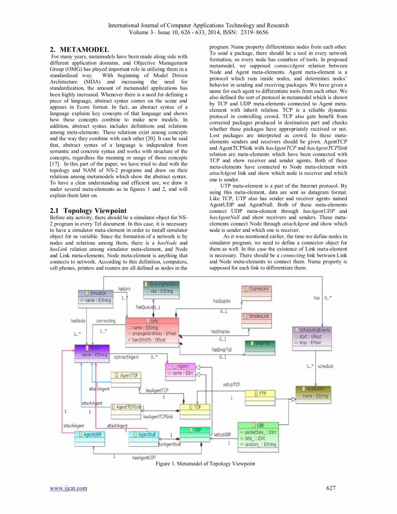
2.1 Topology Viewpoint Before any activity, there should be a simulator object for NS-2 program in every Tel document. In this case, it is necessary to have a simulator meta-element in order to install simulator object for ns variable. Since the formation of a network is by nodes and relations among them, there is a hasNode and hasLink relation among simulator meta-element, and Node and Link meta-elements. Node meta-element is anything that connects to network. According to this definition, computers, cell phones, printers and routers are all defined as nodes in the
program. Name property differentiates nodes from each other. To send a package, there should be a tool in every network formation, so every node has countless of tools. In proposed metamodel, we supposed connectAgent relation between Node and Agent meta-elements. Agent meta-element is a protocol which runs inside nodes, and determines nodes’ behavior in sending and receiving packages. We have given a name for each agent to differentiate tools from each other. We also defined the sort of protocol in metamodel which is shown by TCP and UDP meta-elements connected to Agent meta-element with inherit relation. TCP is a reliable dynamic protocol in controlling crowd. TCP also gets benefit from corrected packages produced in destination part and checks whether these packages have appropriately received or not. Lost packages are interpreted as crowd. In these meta-elements senders and receivers should be given. AgentTCP and AgentTCPSink with hasAgentTCP and hasAgentTCPSink relation are meta-elements which have been connected with TCP and show receiver and sender agents. Both of these meta-elements have connected to Node meta-element with attachAgent link and show which node is receiver and which one is sender. UTP meta-element is a part of the Internet protocol. By using this meta-element, data are sent as datagram format. Like TCP, UTP also has sender and receiver agents named AgentUDP and AgentNull. Both of these meta-elements connect UDP meta-element through hasAgentUDP and hasAgentNull and show receivers and senders. These meta-elements connect Node through attachAgent and show which node is sender and which one is receiver.
As it was mentioned earlier, the time we define nodes in simulator program, we need to define a connector object for them as well. In this case the existence of Link meta-element is necessary. There should be a connecting link between Link and Node meta-elements to connect them. Name property is supposed for each link to differentiate them.
Figure 1. Metamodel of Topology Viewpoint
International Journal of Computer Applications Technology and Research Volume 3– Issue 10, 626 - 633, 2014, ISSN: 2319–8656
www.ijcat.com 628
Each link also has own band width property as bandwidth and distribution delay as propagationDelay which are shown in proposed metamodel. Any link may have duplex or simplex relation with nodes. For this reason, DuplexLink and SimplexLink meta-elements have been connected to Link meta-element using hasDuplex and hasSimplex relations. It should be said that in NS-2 programs, queues are performed as a part of links; therefore, there is a hasQueue relation between Link and QueueingDiscipline meta-elements. QueueingDiscipline meta-element sends and reveives buffers in each node. On the other hand, size property has been defined to show the length of the queue and limit the size of the link. We also can define the type of the queue for every Link meta-element. In proposed metamodel, we supposed DropTail meta-element whose structure enables it to drop the latest package by the time the queue capacity finishes. In addition to all items mentioned above, every simulator has an event timer which schedules the simulations. In Proposed metamodel, we name it as schedulingEvents and suppose has link for it which includes start and stops points to show commence and end points. Since NS is a discrete event simulator, TCLs are being defined by the time events happen. In this case, this meta-element determines start and stop points of applications and connects to SchedulingEvents through schedule meta-element. It should be noted that Application meta-element includes FTP meta-element (this is the first attempt to make standards in file transportation in networks based on TCP protocols) and CBR meta-element (this meta-element sends bits with fixed rate and has PacketSize, rate and random properties). In these meta-elements, inherit concept is attendant, in a way that, both FTP and CBR meta-elements acquire Application meta-element characteristics. This issue is important because it supports hierocracy concepts.
It should be said that, FTP meta-element, uniquely, uses TCP protocol (it never uses UDP protocol). There is setupTCP between TCP elements that is responsible for scheduling.
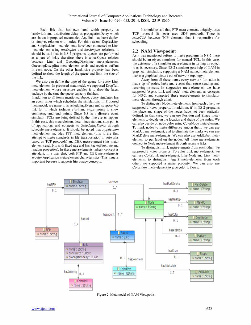
2.2 NAM Viewpooint As it was mentioned before, to make programs in NS-2 there should be an object simulator for manual TCL. In this case, the existence of a simulator meta-element in turning an object to ns is necessary. Since NS-2 simulator gets help of NAM in graphical simulation, supposing a NAM named meta-element makes a graphical picture out of network topology.
Away from all these items, every network formation is made up of nodes, links and events that cause sending and receiving process. In suggestive meta-elements, we have supposed (Agent, Link and node) meta-elements as concepts for NS-2, and connected these meta-elements to simulator meta-element through a link.
To distinguish Node meta-elements from each other, we supposed a name property. In addition, if in NS-2 programs the place and shape of the nodes have not been statically defined, in that case, we can use Position and Shape meta-elements to decide on the location and shape of the nodes. We can also decide on node color using ColorNode meta-element. To mark nodes to make difference among them, we can use MarkUp meta-element, and to eliminate the marks we can use MarkDelete meta-elements. We can also use AddLabel meta-element to put label on the nodes. All these meta-elements connect to Node meta-element through separate links.
To distinguish Link meta-elements from each other, we supposed a name property. To color Link meta-element, we can use ColorLink meta-element. Like Node and Link meta-elements, to distinguish Agent meta-elements from each other, we supposed a name property. We can also use ColorFlow meta-element to give color to flows.
Figure 2. Metamodel of NAM Viewpoint
International Journal of Computer Applications Technology and Research Volume 3– Issue 10, 626 - 633, 2014, ISSN: 2319–8656
www.ijcat.com 629
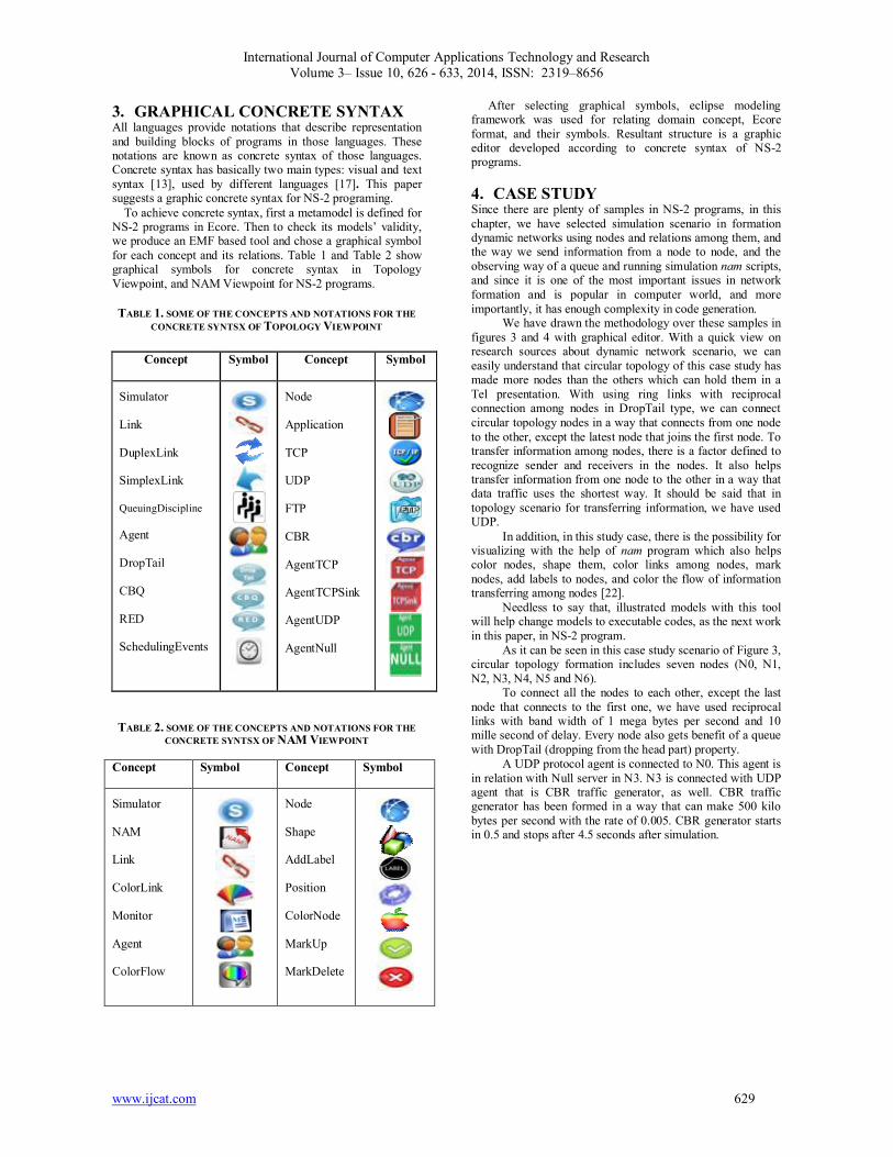
3. GRAPHICAL CONCRETE SYNTAX All languages provide notations that describe representation and building blocks of programs in those languages. These notations are known as concrete syntax of those languages. Concrete syntax has basically two main types: visual and text syntax [13], used by different languages [17]. This paper suggests a graphic concrete syntax for NS-2 programing. To achieve concrete syntax, first a metamodel is defined for NS-2 programs in Ecore. Then to check its models’ validity, we produce an EMF based tool and chose a graphical symbol for each concept and its relations. Table 1 and Table 2 show graphical symbols for concrete syntax in Topology Viewpoint, and NAM Viewpoint for NS-2 programs.
TABLE 1. SOME OF THE CONCEPTS AND NOTATIONS FOR THE CONCRETE SYNTSX OF TOPOLOGY VIEWPOINT
TABLE 2. SOME OF THE CONCEPTS AND NOTATIONS FOR THE
CONCRETE SYNTSX OF NAM VIEWPOINT
Concept Symbol Concept Symbol
Simulator
NAM
Link
ColorLink
Monitor
Agent
ColorFlow
Node
Shape
AddLabel
Position
ColorNode
MarkUp
MarkDelete
After selecting graphical symbols, eclipse modeling framework was used for relating domain concept, Ecore format, and their symbols. Resultant structure is a graphic editor developed according to concrete syntax of NS-2 programs.
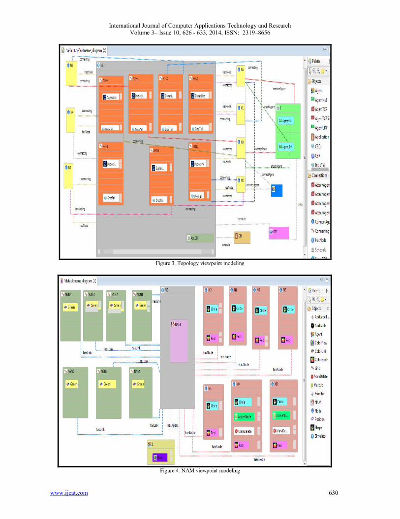
4. CASE STUDY Since there are plenty of samples in NS-2 programs, in this chapter, we have selected simulation scenario in formation dynamic networks using nodes and relations among them, and the way we send information from a node to node, and the observing way of a queue and running simulation nam scripts, and since it is one of the most important issues in network formation and is popular in computer world, and more importantly, it has enough complexity in code generation.
We have drawn the methodology over these samples in figures 3 and 4 with graphical editor. With a quick view on research sources about dynamic network scenario, we can easily understand that circular topology of this case study has made more nodes than the others which can hold them in a Tel presentation. With using ring links with reciprocal connection among nodes in DropTail type, we can connect circular topology nodes in a way that connects from one node to the other, except the latest node that joins the first node. To transfer information among nodes, there is a factor defined to recognize sender and receivers in the nodes. It also helps transfer information from one node to the other in a way that data traffic uses the shortest way. It should be said that in topology scenario for transferring information, we have used UDP.
In addition, in this study case, there is the possibility for visualizing with the help of nam program which also helps color nodes, shape them, color links among nodes, mark nodes, add labels to nodes, and color the flow of information transferring among nodes [22].
Needless to say that, illustrated models with this tool will help change models to executable codes, as the next work in this paper, in NS-2 program.
As it can be seen in this case study scenario of Figure 3, circular topology formation includes seven nodes (N0, N1, N2, N3, N4, N5 and N6).
To connect all the nodes to each other, except the last node that connects to the first one, we have used reciprocal links with band width of 1 mega bytes per second and 10 mille second of delay. Every node also gets benefit of a queue with DropTail (dropping from the head part) property.
A UDP protocol agent is connected to N0. This agent is in relation with Null server in N3. N3 is connected with UDP agent that is CBR traffic generator, as well. CBR traffic generator has been formed in a way that can make 500 kilo bytes per second with the rate of 0.005. CBR generator starts in 0.5 and stops after 4.5 seconds after simulation.
Symbol Concept Symbol Concept
Node
Application
TCP
UDP
FTP
CBR
AgentTCP
AgentTCPSink
AgentUDP
AgentNull
Simulator
Link
DuplexLink
SimplexLink
QueuingDiscipline
Agent
DropTail
CBQ
RED
SchedulingEvents
International Journal of Computer Applications Technology and Research Volume 3– Issue 10, 626 - 633, 2014, ISSN: 2319–8656
www.ijcat.com 630
Figure 3. Topology viewpoint modeling
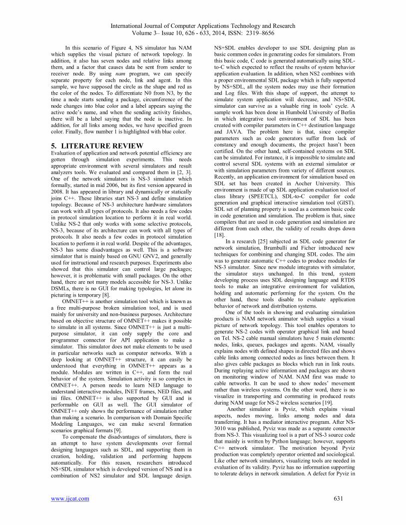
Figure 4. NAM viewpoint modeling
International Journal of Computer Applications Technology and Research Volume 3– Issue 10, 626 - 633, 2014, ISSN: 2319–8656
www.ijcat.com 631
In this scenario of Figure 4, NS simulator has NAM which supplies the visual picture of network topology. In addition, it also has seven nodes and relative links among them, and a factor that causes data be sent from sender to receiver node. By using nam program, we can specify separate property for each node, link and agent. In this sample, we have supposed the circle as the shape and red as the color of the nodes. To differentiate N0 from N3, by the time a node starts sending a package, circumference of the node changes into blue color and a label appears saying the active node’s name, and when the sending activity finishes, there will be a label saying that the node is inactive. In addition, for all links among nodes, we have specified green color. Finally, flow number 1 is highlighted with blue color.
5. LITERATURE REVIEW Evaluation of application and network potential efficiency are gotten through simulation experiments. This needs appropriate environment with several simulators and result analyzers tools. We evaluated and compared them in [2, 3]. One of the network simulators is NS-3 simulator which formally, started in mid 2006, but its first version appeared in 2008. It has appeared in library and dynamically or statically joins C++. These libraries start NS-3 and define simulation topology. Because of NS-3 architecture hardware simulators can work with all types of protocols. It also needs a few codes in protocol simulation location to perform it in real world. Unlike NS-2 that only works with some selective protocols, NS-3, because of its architecture can work with all types of protocols. It also needs a few codes in protocol simulation location to perform it in real world. Despite of the advantages, NS-3 has some disadvantages as well. This is a software simulator that is mainly based on GNU GNV2, and generally used for instructional and research purposes. Experiments also showed that this simulator can control large packages; however, it is problematic with small packages. On the other hand, there are not many models accessible for NS-3. Unlike DSMLs, there is no GUI for making typologies, let alone its picturing is temporary [8].
OMNET++ is another simulation tool which is known as a free multi-purpose broken simulation tool, and is used mainly for university and non-business purposes. Architecture based on objective structure of OMNET++ makes it possible to simulate in all systems. Since OMNET++ is just a multi-purpose simulator, it can only supply the core and programmer connector for API application to make a simulator. This simulator does not make elements to be used in particular networks such as computer networks. With a deep looking at OMNET++ structure, it can easily be understood that everything in OMNET++ appears as a module. Modules are written in C++, and form the real behavior of the system. Simulation activity is so complex in OMNET++. A person needs to learn NED language to understand interactive modules, INET frames, NED files, and ini files. OMNET++ is also supported by GUI and is performable on GUI as well. The GUI simulator of OMNET++ only shows the performance of simulation rather than making a scenario. In comparison with Domain Specific Modeling Languages, we can make several formation scenarios graphical formats [9].
To compensate the disadvantages of simulators, there is an attempt to have system developments over formal designing languages such as SDL, and supporting them in creation, holding, validation and performing happens automatically. For this reason, researchers introduced NS+SDL simulator which is developed version of NS and is a combination of NS2 simulator and SDL language design.
NS+SDL enables developer to use SDL designing plan as basic common codes in generating codes for simulators. From this basic code, C code is generated automatically using SDL-to-C which expected to reflect the results of system behavior application evaluation. In addition, when NS2 combines with a proper environmental SDL package which is fully supported by NS+SDL, all the system nodes may use their formation and Log files. With this shape of support, the attempt to simulate system application will decrease, and NS+SDL simulator can survive as a valuable ring in tools’ cycle. A sample work has been done in Humbold University of Berlin in which integrative tool environment of SDL has been created with compiler parameters in C++ destination language and JAVA. The problem here is that, since compiler parameters such as code generators suffer from lack of constancy and enough documents, the project hasn’t been certified. On the other hand, self-contained systems on SDL can be simulated. For instance, it is impossible to simulate and control several SDL systems with an external simulator or with simulation parameters from variety of different sources. Recently, an application environment for simulation based on SDL set has been created in Aocher University. This environment is made of up SDL application evaluation tool of class library (SPEETCL), SDL-to-C compiler for code generation and graphical interactive simulation tool (GIST). SDL set of planning property is used as a common basic code in code generation and simulation. The problem is that, since compilers that are used in code generation and simulation are different from each other, the validity of results drops down [18].
In a research [25] subjected as SDL code generator for network simulation, Brumbulli and Ficher introduced new techniques for combining and changing SDL codes. The aim was to generate automatic C++ codes to produce modules for NS-3 simulator. Since new module integrates with simulator, the simulator stays unchanged. In this trend, system developing process uses SDL designing language and RTDS tools to make an integrative environment for validation, holding and automatic performing for the system. On the other hand, these tools disable to evaluate application behavior of network and distribution systems.
One of the tools in showing and evaluating simulation products is NAM network animator which supplies a visual picture of network topology. This tool enables operators to generate NS-2 codes with operator graphical link and based on Tel. NS-2 cable manual simulators have 5 main elements: nodes, links, queues, packages and agents. NAM, visually explains nodes with defined shapes in directed files and shows cable links among connected nodes as lines between them. It also gives cable packages as blocks which run in link routs. During replaying active information and packages are shown on monitoring window of NAM. NAM first was made to cable networks. It can be used to show nodes’ movement rather than wireless systems. On the other word, there is no visualize in transporting and commuting in produced routs during NAM usage for NS-2 wireless scenarios [19].
Another simulator is Pyviz, which explains visual aspects, nodes moving, links among nodes and data transferring. It has a mediator interactive program. After NS-3010 was published, Pyviz was made as a separate connector from NS-3. This visualizing tool is a part of NS-3 source code that mainly is written by Python language; however, supports C++ network simulator. The motivation beyond Pyviz production was completely operator oriented and sociological. Like other network simulators, visualizing tools are needed in evaluation of its validity. Pyviz has no information supporting to tolerate delays in network simulation. A defect for Pyviz in
International Journal of Computer Applications Technology and Research Volume 3– Issue 10, 626 - 633, 2014, ISSN: 2319–8656
www.ijcat.com 632
moving nodes in visualizing is that nodes pay no attention to moving area of Pyviz so they disorder program while it is running [21]. Another tool in showing simulation results is Scalar that can be used in producing scalar files. It enables the extraction of a single text which can be read by MATLAB, and spread sheets such as Excel and open Office Cale. All these external applications are strongly able to statistical analyze and visualize. On the other hand, OMNET++ cannot improve its capacity. On the contrary, OMNET++ mainly focuses on real simulators and pays no attention to the simulation results [19]. All the existent simulators have their own defect in Domain Specific Modeling Language. A Domain Specific Modeling Language not only is able to model a graphical program and control it, but also can change that model into other peer models and improve language semantics, generate performable codes on popular languages and improve efficiency. In this case the speed of code generation increases and the risk of error arising decreases, as a result, overall efficiency will increase.
6. CONCLUSION In this paper, NS-2 programs are selected as regarded domain for developing a DSML. Considering simulation concepts and relations, abstract syntax was formally defined as a metamodel proportional to language complexities. Then, the concrete syntax was prepared in the form of appropriate notations and a graphic modeling editor supported by a graphical tool. Also, a instance model was represented by this tool to illustrate the use of proposed methodology. As our future work, we are going to focus on the formal semantic representations for NS-2 programs in the form of constraints [24]. To identify language statements and their meanings considering language, semantic is a must. Otherwise, some imaginations may form about language, leading to its incorrect application. As another future work, to have the new language applicable, we aim to use the models as input for code generation. This will be realized in the form of operational semantics and model transformation. Finally, integrated tools will be developed for supporting these features of NS-2 programs in target language.
ACKNOWLEDGMENT The authors would like to acknowledge Dr. Ali Akbar Dadjouyan for his helpful comments and suggestions during the preparation of this study regarding NS-2 programing. Also, Elham Azadi Marand would like to acknowledge Moharram Challenger, her M.Sc supervisor, for all his guidance and support during her thesis study.
REFERENCES [1] Azadi, E.. and M.Challenger, 2013. Assessment and
Comparison of designing methods, Implementation and required tools for Domain Specific Languages (DSLs) development. First National Conference on Advances in computer science and information retrieval approaches. Young Researchers Club, Islamic Azad University. Roudsar and Amlash, Iran, pp. 1-8. (in Persian).
[2] Azadi, E., E. Azadi and M. Challenger, 2014. Assessment and Comparison of Network Simulation Tools and Languages. 8th Symposium on Advances in Science & Technology (8th SASTech 2014), Mashhad, Iran, pp. 1-8, (in Persian).
[3] Azadi, E., E. Azadi and M. Challenger, 2014. Assessment and Comparison of Topology generation tool and View and analyze the results of network simulation. 8th Symposium on Advances in Science & Technology (8thSASTech 2014), Mashhad, Iran, pp. 1-8. (in Persian).
[4] Lacage, M. and T.R. Henderson, 2006. Yet Another Network Simulator. In Proceedings of the Seventh ACM Symposium on Modeling. pp. 1-8.
[5] Barr, R., V. Haas and R. Renesse, 2004. JiST: An efficient approach to simulation using virtual machines. Software practice and Experience. pp.1-7.
[6] Siraj, S., A.K. Gupta and R. Badgujar, 2012. Network Simulation Tools Survey. International Journal of Advanced Research in Computer and Communication Engineering. Vol. 1, Issue 4, pp. 1-10.
[7] Naicken, S., A. Basu, B. Livingston and S. Rodhetbhai, 2006. A Survey of Peer-to-Peer Network Simulators. Proceedings of the Seventh Annual Postgraduate Symposium, Liverpool, UK. Pp. 1-8.
[8] Thomas, C. 2011. NS-3 Simulation Of Wimax Networks. MSc Thesis. Department of Computer Science & Engineering - Washington University in St. Louis. pp. 1-60.
[9] Hogie, L. 2007. Mobile Ad Hoc Networks: Modelling, Simulation and Broadcast-based Applications. Ph.D thesis in Computer Science. University of Luxembourg.
[10] Montresor, A. and M. Jelasity. 2009. PeerSim: a scalable P2P simulator. In Proc. of the 9th Int. Conference on Peer-to-Peer (P2P’09). pp. 1-2.
[11] Ezreik, A. and A. Gheryani, 2012. Design and Simulation of Wireless Network using NS-2. 2nd International Conference on Computer Science and Information Technology (ICCSIT'2012). Pp. 157-161.
[12] Weingartner, E., H. Lehn and K. Wehrle, 2009. A Performance Comparison of Recent Network Simulators. in: Proceedings of the IEEE International Conference on Communications 2009 (ICC 2009), Dresden, Germany, IEEE, pp:1 – 5.
[13] Demirkol, S., M. Challenger, S. Getir, T. Kosar, G. Kardas and M. Mernik, 2013. A DSL for the Development of Software Agents Working in the Semantic Web Environment. International Journal of Computer Science and Information Systems (ComSIS). (Accepted) DOI: 10.2298/CSIS121105044D.
[14] Kent, S. 2002. Model Driven Engineering. Lecture Notes in Computer Science Volume 2335, pp 286-29.
[15] Schmidt, D.S. 2006. Model-driven engineering. IEEE Computer Society, pp. 25-31.
[16] Voelter, M., S. Benz, C. Dietrich, B. Engelman, M. Helander, L. Kats, E. Visser and G. Wachsmuth, 2014. DSL Engineering. 2010-1013, Available online at: http://dslbook.org.
[17] Clark, T., P. Sammut and J. Willans, 2008. Applied Meta Modeling A Foundation For Language Driven Development. available online at: http://eprints.mdx.ac.uk/6060/1/Clark-Applied_Metamodelling_(Second_Edition)[1].pdf. pp .1-224.
[18] Kuhn, T., A. Geraldy, R. Gotzhein and F. Rothl, 2005. ns+SDL – The Network Simulator for SDL Systems. A. Prinz, R. Reed, and J. Reed (Eds.): SDL 2005, LNCS 3530, pp. 103–116.
[19] Reineck, K.M. 2008. Evaluation and Comparisonof Network Simulation Tools. Master Thesis, University of Applied Sciences Bonn Rhein-Sieg, Department of Computer Science.
[20] Challenger, M., S. Getir, S. Demirkol and G. Kardas, 2011. A Domain Specific Metamodel for Semantic Web enabled Multi-agent Systems. Lecture Notes in Business Information Processing, vol. 83, pp. 177-186. Multi-agent Systems", Lecture Notes in Business Information Processing , Vol. 83, pp. 177-186, 2011.
[21] Kurkowski, S., T. Camp and M. Colagrosso, 2004. A Visualization and Animation Tool for NS-2 Wireless Simulations: iNSpect. Dept of Mathematical and Computer Sciences.
International Journal of Computer Applications Technology and Research Volume 3– Issue 10, 626 - 633, 2014, ISSN: 2319–8656
www.ijcat.com 633
[22] Ekram, H. and I. Teerawat, 2009. Introduction to Network Simulator NS2. Springer New York Dordrecht Heidelberg London. ISBN: 978-1-4614-1405-6.
[23] Challenger, M., Demirkol S., Getir S., Kosar T., Kardas G., Mernik M, 2014. On the use of a Domain-Specific Modeling Language in the Development of Multiagent Systems. International Journal of Engineering Applications of Artificial Intelligence, Vol. 28, pp. 111–141.
[24] Getir, S., M. Challenger and G. Kardas, 2014. The Formal Semantics of a Domain-specific Modeling Language for Semantic Web enabled Multi-agent Systems. International Journal of Cooperative Information Systems, vol. 23, issue 3, pp. 1450005.
[25] Brumbulli, M and J. Fisher, 2011. SDL Code Generation for Network Simulators. Springer-Verlag Berlin Heidelberg 2005, pp. 103–116.