Embed Size (px)
Citation preview
A METHOD FOR THE TOLERANCE ANALYSIS OF BEARING
SEATS FOR CYLINDRICAL ROLLER BEARINGS IN RESPECT
TO OPERATING CLEARANCE AND FATIGUE LIFE
Aschenbrenner, Alexander; Wartzack, Sandro
Friedrich-Alexander-University Erlangen-Nuremberg, Germany
Abstract
Roller bearings are used in a vast variety of mechanical applications and are often highly stressed
machine elements. Therefore the fatigue life of roller bearings can determine the reliability and service
life of these mechanical systems. The fatigue life of a roller bearing is greatly affected by its operating
clearance and the design of the adjacent components (namely shaft and housing). Especially the
geometric dimensioning and tolerancing of the bearing seats can have great influence on the operating
clearance and therefore the fatigue life of a roller bearing. In this article a method for the statistical
tolerance analysis of the operating clearance of cylindrical roller bearings is presented. The method uses
a discrete geometry representation coupled with contact detection algorithms for the determination of
the operating clearance. The results are thereafter coupled with the calculation of the fatigue life.
Statistical analysis of the results assists an engineering designer when choosing a robust design for the
bearing seats.
Keywords: Tolerance representation and management, Robust design, Uncertainty, Cylindrical roller
bearing
Contact:
Alexander Aschenbrenner
Friedrich-Alexander-University Erlangen-Nuremberg
Mechanical Engineering
Germany
21ST INTERNATIONAL CONFERENCE ON ENGINEERING DESIGN, ICED17 21-25 AUGUST 2017, THE UNIVERSITY OF BRITISH COLUMBIA, VANCOUVER, CANADA
Please cite this paper as:
Surnames, Initials: Title of paper. In: Proceedings of the 21st International Conference on Engineering Design (ICED17),
Vol. 4: Design Methods and Tools, Vancouver, Canada, 21.-25.08.2017.
79
ICED17
1 INTRODUCTION
Each time a part rotates, a rolling bearing might be involved – from small dental drills to huge wind
turbines. In general, a roller bearing separates two components, which can be rotated relative to one
another, while still allowing a flow of force between both parts. In mechanical systems rolling bearings
are often mounted to a shaft or an axel and into a housing. As rolling bearings are highly stressed
machine elements, their fatigue life could determine the reliability and service life (Guo et al., 2015) of
such mechanical systems and therefor the maintenance costs.
Roller bearings normally possess internal clearance as well as clearance due to a loose fit of the bearings
rings. Generally, such clearance could have a negative effect on the service life of machine components.
For instance, the fatigue life of a rolling bearing depends – among other things – on the operating internal
clearance according to ISO/TS 16281 (2008). This correlation has also been described by Oswald,
Zaretsky and Poplawski (2009, 2012) who performed various computational analyses on interference
fitted low-speed cylindrical roller bearings and deep-groove ball bearings. The authors show that the
fatigue life of radially loaded roller and ball bearings can significantly increase or decrease due to the
internal clearance of a bearing. For instance, a small negative internal clearance (preloading) has a
positive effect on the fatigue life. However, if there is too much preloading a rapid decline of the fatigue
life occurs. On the other hand, an increasing positive internal clearance also decreases the fatigue life.
Hence, an engineering designer must act diligently when choosing a rolling bearing and determining a
bearing seats in order to achieve an operating clearance that prolongs a rolling bearings fatigue life.
Ye and Wang (2015) suggest a detailed calculation method for the optimization of the fatigue life of
cylindrical roller bearings. The method is based on a quasi-dynamic model of bearings. Besides tilting
of the bearing components, thermal expansion and centrifugation this method also allows the
consideration of the assembly interference between shaft and inner ring. After evaluating an optimal
operating clearance, the calculation method could be used to determine the optimal assembly
interference between shaft and inner ring. However, the authors don't specify how dimensional
tolerances of the bearing seat should be specified. The fit between the housing bore and the outer ring
is disregarded too. However, the rings of cylindrical roller bearings could be separately mounted,
allowing a tight fit for both rings (Eschmann, Hasbargen and Weigand, 1985). According to the
recommendations of the bearing manufacturers (e. g. Schaeffler (2012) or SKF (2014)) especially for
circumferential load on the outer ring, a press fit between the housing bore and the outer ring is more
important than a tight fit on the inner ring.
What is more, the authors neglect geometric deviations of the bearing components as well as of the
adjacent components. But geometric deviations are observable on each component due to an imprecision
that is inherent to all manufacturing processes (Zhang et al., 2011). In the case of roller bearings,
geometric deviations on the raceways or the rolling elements could affect the initial clearance of a roller
bearing. Geometric deviations on the connecting surfaces of the bearing components and on their
adjacent components may also affect the behavior of the bearing seat. These uncertainties make it hardly
possible to achieve a certain value for the assembly interference and the operating clearance. Geometric
dimensioning and tolerancing (GD&T) at least limits the allowable geometric deviations a priori.
Nevertheless, it is often difficult to set these limits, as the functional behavior of the components could
be influenced in many ways (Schleich and Wartzack, 2013).
In this article a method is presented that allows the analysis of the geometric dimensioning and
tolerancing of a bearing seat for cylindrical roller bearings with respect to their fatigue life. The method
could therefore assist an engineering designer when determining the tolerance specification of a bearing
seat. The method adds the calculation of the reference rating life (ISO/TS 16281, 2008) and the
deformation of the bearing rings to the concept for the consideration of geometrical deviations in the
evaluation of bearing clearance (Aschenbrenner and Wartzack, 2016). After some basic information
about cylindrical roller bearings in section 2, a description of the method is given in section 3.
Afterwards the application of the method is presented for a use case in section 4. The paper closes with
a conclusion and an outlook in section 5.
80
ICED17
2 BASICS ABOUT CYLINDRICAL ROLLER BEARINGS
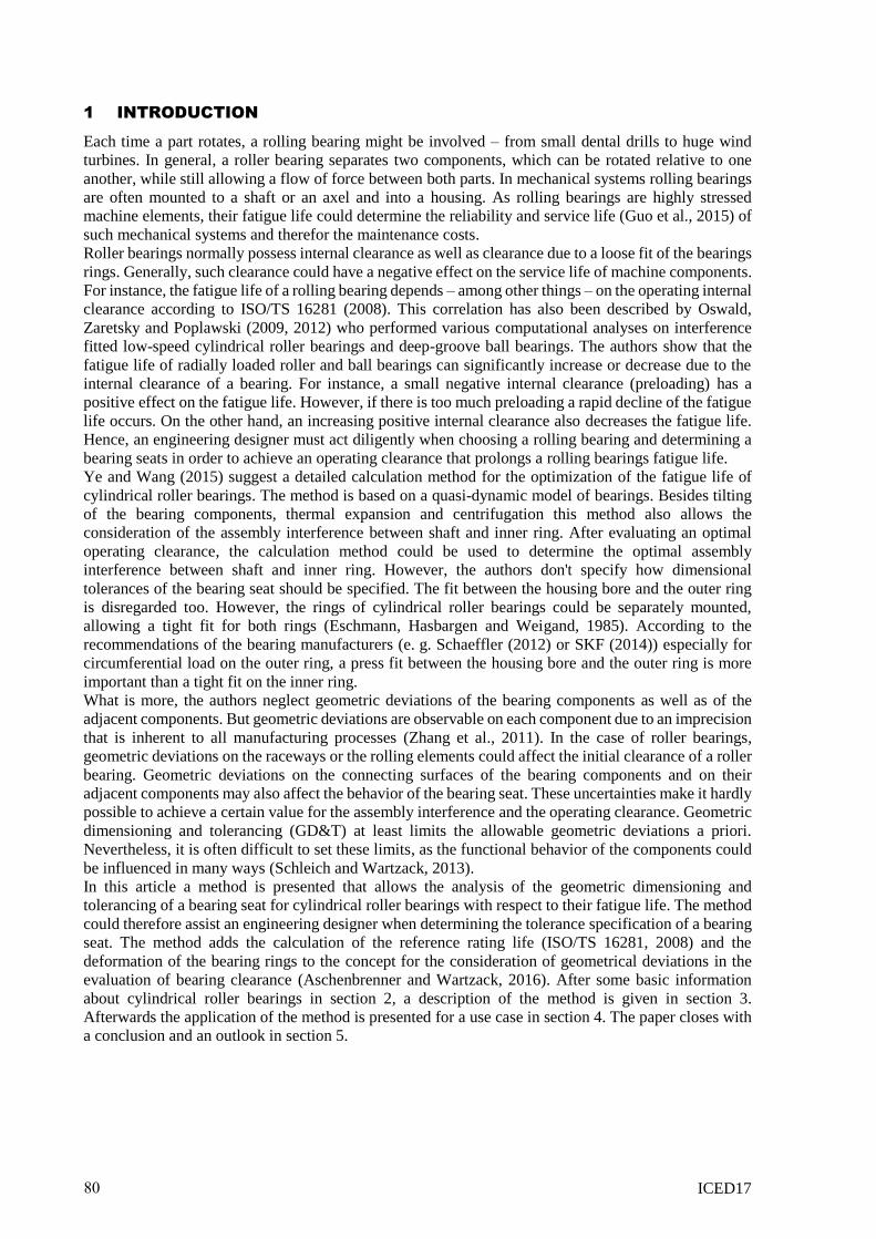
Figure 1. a) General structure of a cylindrical roller bearing b) Illustration of the radial internal clearance of a roller bearing
Figure 1 a) shows the general structure of a cylindrical roller bearing. Although several cylindrical roller
bearing types exist (e. g. N, NU, NJ or NUP), they all have in common that they consist of an outer ring,
an inner ring and several rollers rotating between the two bearing rings. In order to guarantee the rolling
behavior of the rollers, each bearing ring provides a very precise raceway. Ribs ensure axial guidance
of the rollers. Depending on the type of cylindrical roller bearing the raceways could be surrounded by
none, one or two ribs. Because of the relatively large contact area, cylindrical roller bearings can absorb
high radial forces. But only those cylindrical roller bearing types having ribs on both bearing rings could
deal with (comparably small) thrust loadings at all (namely NJ, NF, NH and NUP). Hence, cylindrical
roller bearings are often used as floating bearings. Cylindrical roller bearings can be disassembled.
Therefore the bearing rings could be separately mounted with a tight fit onto the shaft and into the
housing. The dimensional tolerances for the exterior dimensions of radial rolling bearings are
standardized and classified in ISO 492 (2014).
The initial bearing clearance of radial rolling bearings is standardized too (ISO 5753-1 (2009)). Actually,
roller bearings can be categorized by their clearance class. As pictured in Figure 1 b), the internal bearing
clearance can be defined as the distance for which the inner ring can be moved relatively to the outer
ring. In general, one must distinguish between the initial clearance, the installation clearance and the
operating clearance. The initial clearance is influenced by the manufacturing and assembly of the
bearing components. Bearing manufactures perform elaborate steps during these processes, like specific
grinding or sorting of the bearing components, to produce rolling bearings of a particular initial bearing
clearance. Beside uncertainties related to the exterior dimensions of a rolling bearing the installation
clearance is mainly influenced by the geometric deviations of a rolling bearing's adjacent components
(namely shaft and housing). Due to the relatively low wall thickness of the bearing rings they can deform
during the mounting process. For instance, an outer ring will contract and an inner ring will expand
when mounted with a tight fit. Therefore the installation clearance is normally smaller than the initial
clearance. What is more, the geometric deviations of the adjacent components can transfer to the
raceway (Eschmann, Hasbargen and Weigand, 1985) and overlay with existing geometric deviations. In
general, geometric deviations on the raceways could negatively influence the behavior of a rolling
bearing in terms of vibration or load distribution (e. g. Wardle (1988), Harsha, Sandeep and Prakash
(2003) etc.). The operational clearance mainly depends on the thermal gradient within a bearing.
Normally the inner parts (i. e. shaft and inner ring) are warmer than the outer parts (i. e. outer ring and
housing) because of an increased heat transfer of the housing (e. g. heat conduction, thermal radiation
etc.). The hotter inner parts have a greater thermal expansion than the cooler outer parts, which causes
further reduction of the bearing clearance. Hence, the operational clearance is usually smaller than the
installation clearance.
As mentioned previously, the internal bearing clearance influences the fatigue life of a rolling bearing
according to the calculation formulas of the reference rating life in ISO/TS 16281. In general, a lamina
model that cuts all rollers into several laminae is used. For each lamina the dynamic load rating and
dynamic load is calculated. The dynamic load rating of a lamina can be easily calculated using the
calculation rules provided in ISO/TR 1281-1 (2008) and the information of the bearing manufactures
regarding the dynamic load rating of a specific bearing type. For the determination of the dynamic
loading of a roller lamina a force and momentum equilibrium are iteratively solved. Due to tilting and a
surface profile of the bearing components (such as crowning of rollers) an increased stress can occur in
those laminae which are near to an edge of a roller. For standard barrel-like crowns a formula for the
increased edge stress is provided. For more complex surface profiles an advanced numerical solution
for contact problems should be applied (such as: De Mul, Kalker and Frederiksson, 1986).
81
ICED17
3 METHOD FOR THE TOLERANCE ANALYSIS OF ROLLER BEARING
OPERATING CLEARANCE AND FATIGUE LIFE
According to Dantan et al. (2012) a tolerance analysis has to deal with the representation of the
geometrical deviations, the calculation of the behavior of a system with deviating components and the
utilization of proper analysis methods (such as worst-case searching or statistical analysis). As shown
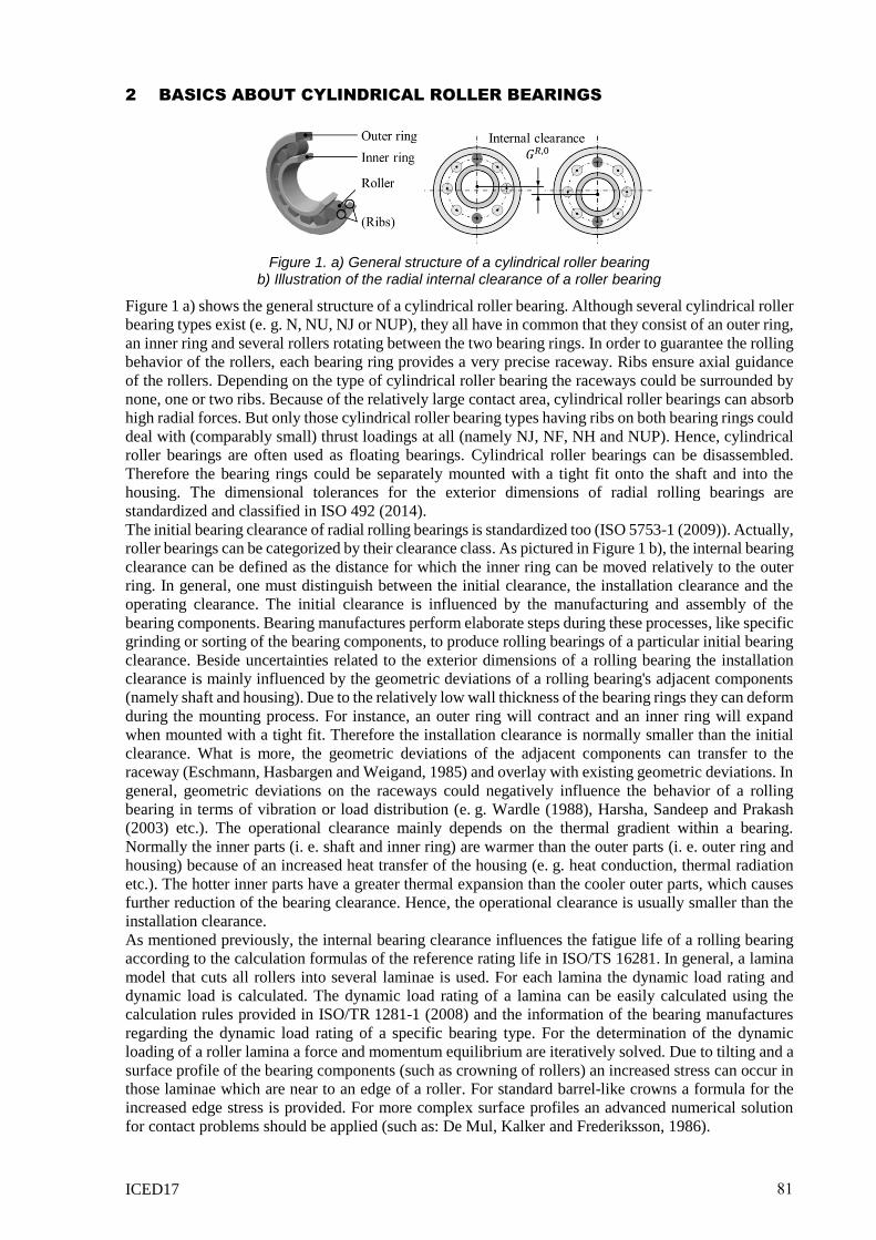
in Figure 2, the structure of the herein presented method follows this threefold division.
Figure 2. Necessary steps for the tolerance analysis of the operating clearance and fatigue life of cylindrical roller bearings
First of all, a large number of virtual components with their specific dimensional and geometric
deviations are sampled. Utilizing the dimensions of the raceways a roller sort is selected for each roller
bearing, whereby deviations may also occur within a roller sort. After the generation of the non-ideal
components the operating clearances of all virtual roller bearings are calculated. These results are then
used to determine the fatigue life of each roller bearing. Operating clearance and fatigue life define
functional capabilities of cylindrical roller bearings and are therefore considered as functional key
characteristics (FCKs) (Thornton, 1999) For both FCKs a statistical analysis is performed in which
statistical characteristics are evaluated, such as the sample mean, the sample standard deviation and the
correlation coefficients. Finally, this information can be used to purposefully adjust the tolerance
specification of the bearing seat in order to increase the fatigue life of the roller bearings. In the following
three subsections each of the first three steps is described in greater detail.
3.1 Generation of the non-ideal components
Following Schleich and Wartzack (2014), the non-ideal geometry is represented by a surface mesh. As
only a 2D-radial cut of each bearing is considered, the surface mesh consists of vertices and edges. For
the edges the degree of the trial function can be chosen. However, computation time could increase
tremendously with the degree. Therefore only linear edges are utilized. The vertices are equidistantly
distributed on the surfaces of the components (in terms of angular distance). The radial coordinate of
each vertex could be obtained using mathematical descriptions such as the Discrete Fourier Transforms
(Colosimo et al., 2004).
For the generation of the non-ideal components the geometric and dimensional deviations of the bearing
rings, the shaft and the housing bore are sampled for each roller bearing. Bearing manufactures normally
try to manufacture bearing components in such a manner, that the actual initial bearing clearance is near
to the mean initial bearing clearance of a specific clearance class. For this purpose the rolling elements
are classified by their diameter, whereby each class has very tight specification limits. For instance, for
roller diameters smaller than 26 mm the maximum allowable radial deviation is less than 1 µm (DIN
5402-1, 2014). The actual raceway diameters can be used to select a roller diameter class for each roller
82
ICED17
bearing individually. In practice, however, only a couple of classes are considered for reasons of
capacity.
When the deviations of all components have been sampled, the mounting of the bearing rings could be
simulated. In general, a deformation of the bearing rings will only occur if there are interferences
between the bearing rings and their adjacent components. In this case the deformation could be evaluated
using a Finite Element Simulation. However, for statistical reliable results a large number of rolling
bearings must be evaluated and Finite Element Simulations come with high computational costs. At
least the dimensional deformation of the bearing rings (i. e. contraction of the outer ring and expansion
of the inner ring) can be easily approximated analytically following the calculation rules in DIN 7190-
1 (2013). These calculation rules are based on the calculation of the cylinder stress in thin- or thick-
walled cylinders (depending on the diameter ratio) (Schmid, Hamrock and Jacobson, 2014).
Unfortunately, geometric deviation like out-of-roundness can't be considered. Therefore a modified
calculation formula is used: Utilizing the discrete geometry representation, the components are
subdivided into very thin slices. The actual interference is calculated for each slice. Next, each slice is
treated like a closed cylinder and the radial deformation of this cylinder is calculated according to the
calculation rules for interference fits. The results of each slice are then transferred to the respective
raceway. This modification was compared to several Finite Element Simulations. As the modification
tends to overestimate the deformation of the bearing rings, a linear regression model based on the results
of the Finite Element Simulation was implemented. The results of the regression model are quite
promising (coefficient of prognosis up to 99.70 % and a mean absolute deviation around 0.01 µm).
However, the modification has only been tested for harmonic out-of-roundness deviations (waviness).
Thus, further testing is necessary.
Besides the deformation of the bearing rings due to mounting, the thermal expansion of the bearing
components must be considered too. For this purpose the linear thermal expansion of the components is
calculated. According to Mitrović et al (2015) the temperatures of the bearing components stays almost
constant after run-up. As a result, the temperature of a bearing component is the same for all evaluated
roller bearings.
3.2 Determination of the functional key characteristics
For the calculation of the operating clearance the concept presented in Aschenbrenner and Wartzack
(2016) is used. It follows the approach of Schleich and Wartzack (2014) which uses a ray trace algorithm
for the analysis of a spur gear's run out deviations. The process for the evaluation of the operating
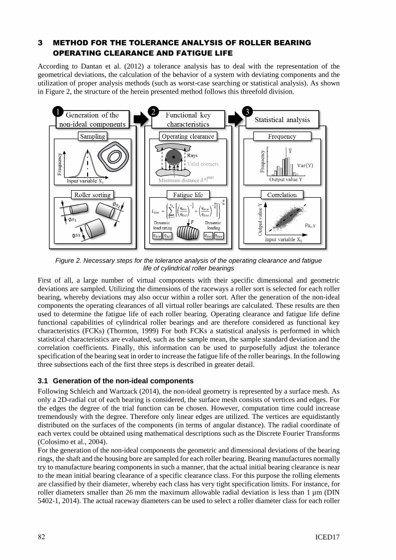
clearance is depicted in Figure 3:
Figure 3. Process for the evaluation of the operating clearance: a) Initial positioning of deformed non-ideal bearing components
b) Registration of the roller on the outer racewayc) Registration of the inner ring on the roller(s) in a predefined directiond) Registration of the inner ring on the roller(s) in the opposing direction
First of all, the non-ideal bearing components are positioned around a fixed center point with the rollers
placed onto the mean bearing diameter in an angular distance equal to the separation angle. In the
following steps, the bearing components are registered on each other. For the registration contact
detection algorithms are employed. According to Kockara et al. (2009) those algorithms can be
distinguished between broad-phase contact detection and narrow-phase contact detection. Broad-phase
algorithms are used to preselect bodies or body features that might be or get in contact. For this purpose,
the real bodies are substituted with simple generic volume elements, like circular or quadratic hit-boxes
in 2D. The computational costs for the contact and collision detection of these substitutes are very low.
In the case of the registration of the bearing components the fact is used that the polar coordinates of
each surface point as well as the center points of the rollers are known or can be easily determined ex
83
ICED17
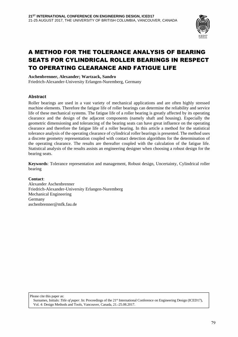
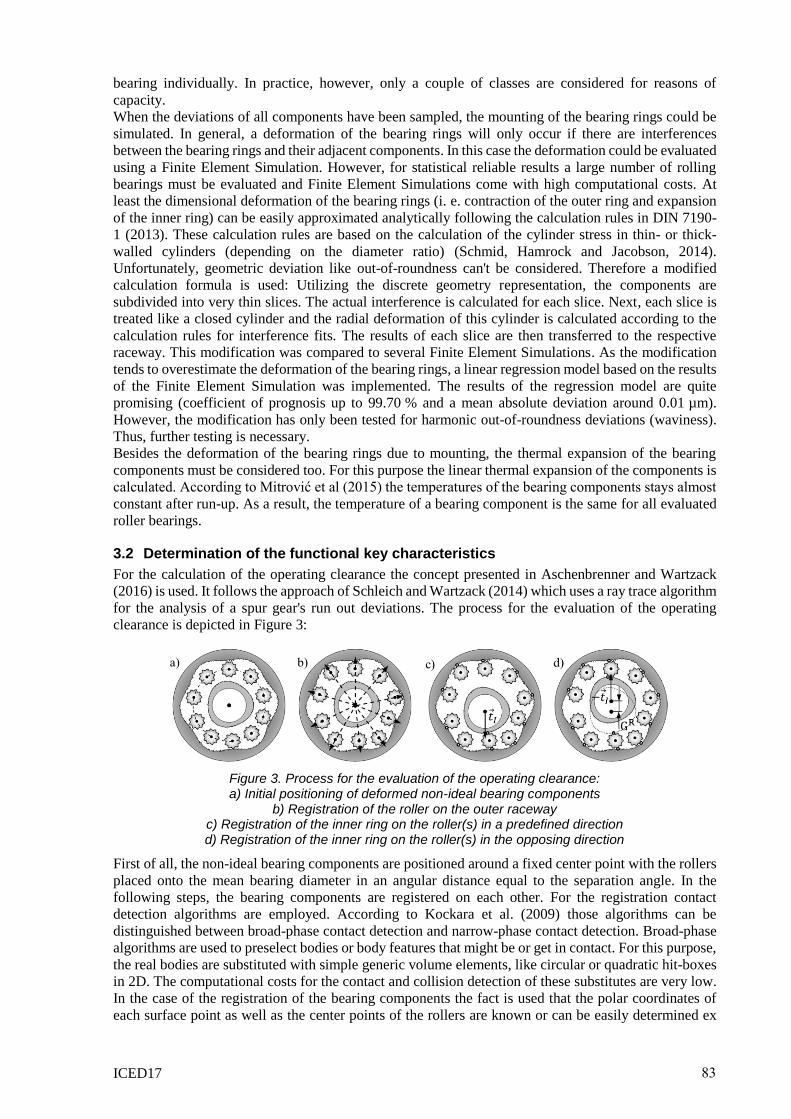
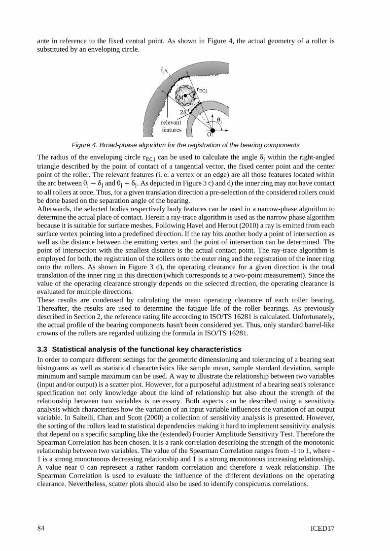
ante in reference to the fixed central point. As shown in Figure 4, the actual geometry of a roller is
substituted by an enveloping circle.
Figure 4. Broad-phase algorithm for the registration of the bearing components
The radius of the enveloping circle rEC,j can be used to calculate the angle δj within the right-angled
triangle described by the point of contact of a tangential vector, the fixed center point and the center
point of the roller. The relevant features (i. e. a vertex or an edge) are all those features located within
the arc between θj − δj and θj + δj. As depicted in Figure 3 c) and d) the inner ring may not have contact
to all rollers at once. Thus, for a given translation direction a pre-selection of the considered rollers could
be done based on the separation angle of the bearing.
Afterwards, the selected bodies respectively body features can be used in a narrow-phase algorithm to
determine the actual place of contact. Herein a ray-trace algorithm is used as the narrow phase algorithm
because it is suitable for surface meshes. Following Havel and Herout (2010) a ray is emitted from each
surface vertex pointing into a predefined direction. If the ray hits another body a point of intersection as
well as the distance between the emitting vertex and the point of intersection can be determined. The
point of intersection with the smallest distance is the actual contact point. The ray-trace algorithm is
employed for both, the registration of the rollers onto the outer ring and the registration of the inner ring
onto the rollers. As shown in Figure 3 d), the operating clearance for a given direction is the total
translation of the inner ring in this direction (which corresponds to a two-point measurement). Since the
value of the operating clearance strongly depends on the selected direction, the operating clearance is
evaluated for multiple directions.
These results are condensed by calculating the mean operating clearance of each roller bearing.
Thereafter, the results are used to determine the fatigue life of the roller bearings. As previously
described in Section 2, the reference rating life according to ISO/TS 16281 is calculated. Unfortunately,
the actual profile of the bearing components hasn't been considered yet. Thus, only standard barrel-like
crowns of the rollers are regarded utilizing the formula in ISO/TS 16281.
3.3 Statistical analysis of the functional key characteristics
In order to compare different settings for the geometric dimensioning and tolerancing of a bearing seat
histograms as well as statistical characteristics like sample mean, sample standard deviation, sample
minimum and sample maximum can be used. A way to illustrate the relationship between two variables
(input and/or output) is a scatter plot. However, for a purposeful adjustment of a bearing seat's tolerance
specification not only knowledge about the kind of relationship but also about the strength of the
relationship between two variables is necessary. Both aspects can be described using a sensitivity
analysis which characterizes how the variation of an input variable influences the variation of an output
variable. In Saltelli, Chan and Scott (2000) a collection of sensitivity analysis is presented. However,
the sorting of the rollers lead to statistical dependencies making it hard to implement sensitivity analysis
that depend on a specific sampling like the (extended) Fourier Amplitude Sensitivity Test. Therefore the
Spearman Correlation has been chosen. It is a rank correlation describing the strength of the monotonic
relationship between two variables. The value of the Spearman Correlation ranges from -1 to 1, where -
1 is a strong monotonous decreasing relationship and 1 is a strong monotonous increasing relationship.
A value near 0 can represent a rather random correlation and therefore a weak relationship. The
Spearman Correlation is used to evaluate the influence of the different deviations on the operating
clearance. Nevertheless, scatter plots should also be used to identify conspicuous correlations.
84
ICED17
4 APPLICATION OF THE METHOD FOR A SIMPLE USE CASE
For the use case a cylindrical roller bearing of the type NU206 with clearance class CN and tolerance
class PN is considered. The target value of the initial bearing clearance is 32.5 µm. The roller bearing is
exposed to a constant dynamic loading of 3000 N which applies as a circumferential load on the outer
ring and as a point load on the inner ring. According to the bearing type the dynamical load rating is
45 kN. The temperature conditions within the bearing are considered constant (inner ring: 72.5°C,
rollers: 70°C and outer ring 67.5°C). The rotational speed should be constant at 1800 rpm.
In this use case only harmonic out-of-roundness deviations (waviness) on the shafts and housing bores
are considered. For comparability, all shafts should have the same number of waves (f S = 7). Also the
number of waves for the housing bores is constant (f B = 6). The dimensional tolerances and roundness
tolerances are chosen according to the recommendations of the bearing manufactures (e. g. Schaeffler
(2012), SKF (2013)).
For the bearing components only dimensional deviations are considered. The exterior dimensions of the
roller bearings correspond to the values in ISO 492. The interior dimensions (namely the raceway and
roller diameters) are a matter for the bearing manufactures. However, the dimensional tolerances of the
adjacent components of needle roller and cage assemblies can be assumed as reference values. For the
rollers three diameter classes are used. The classes form a closed interval for which the values should
be normally distributed across all classes. Except for the installation angles, all other values should be
normally distributed centered at their mean value. Table 1 gives an overview of all ranges and statistical
characteristics for all input variables.
Table 1. Variable values of the initial tolerance specification
Input variable Range Statistical characteristics
Shaft diameter S: [29.980 mm; 29.993 mm ] µ = 29.9865 mm; σ = 2.16̅ µm
Roundness deviation (shaft) aS: [0 µm; 4.5 µm] Bisected normal distribution
µ = 0 µm; σ = 1,5 µm
Installation angle (shaft) θS: [0°; 360°[ Uniform distribution
Housing bore diameter B: [61.970 mm; 62.000 mm] µ = 61.985 mm; σ = 5 µm
Roundness deviation (housing) aB: [0 µm, 6.5 µm] Bisected normal distribution
µ = 0 µm; σ = 2.16̅ µm
Installation angle (shaft) θB: [0°; 360°[ Uniform distribution
Housing outer diameter A: [94 mm; 96 mm] µ = 95 mm; σ = 0. 3̅ mm
Inner ring bore diameter d: [29.990 mm; 30.000 mm] µ = 29.993̅ mm; σ = 1. 1̅ µm
Raceway diameter (inner ring) F: [37.489 mm; 37.500 mm ] µ = 37.4963̅ mm; σ = 1. 2̅ µm
Raceway diameter (outer ring) E: [55.501 mm; 55.529 mm ] µ = 55.5103̅ mm; σ = 3. 1̅ µm
Outer ring outer diameter D: [61.987 mm; 62.000 mm] µ = 61.9956̅ mm; σ = 1. 4̅ µm
Roller diameter s1: [8.988 mm; 8.990 mm[ Normal distribution across all
diameter classes
µ ≈ 8.991 mm; σ = 1 µm s2: [8.990 mm; 8.992 mm[
s3: [8.992 mm; 8.994 mm]
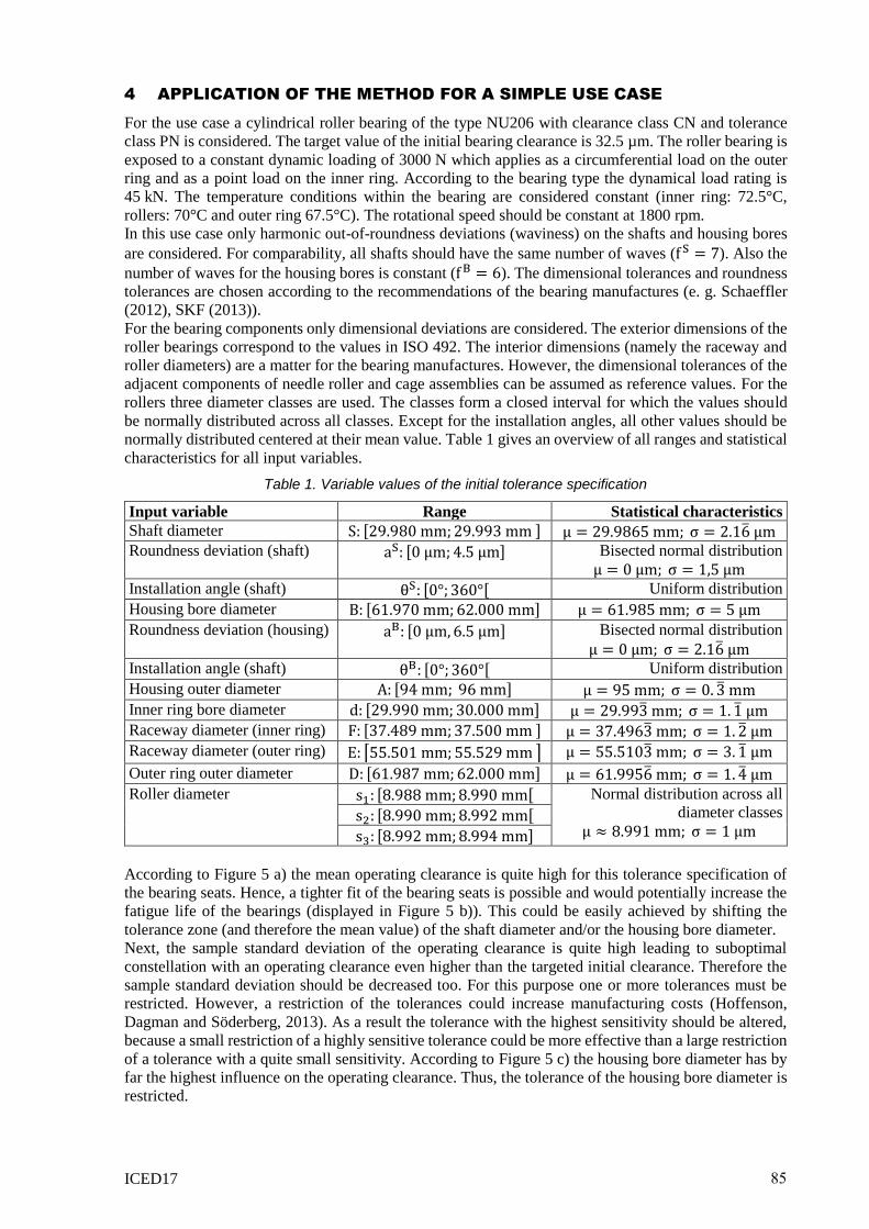
According to Figure 5 a) the mean operating clearance is quite high for this tolerance specification of
the bearing seats. Hence, a tighter fit of the bearing seats is possible and would potentially increase the
fatigue life of the bearings (displayed in Figure 5 b)). This could be easily achieved by shifting the
tolerance zone (and therefore the mean value) of the shaft diameter and/or the housing bore diameter.
Next, the sample standard deviation of the operating clearance is quite high leading to suboptimal
constellation with an operating clearance even higher than the targeted initial clearance. Therefore the
sample standard deviation should be decreased too. For this purpose one or more tolerances must be
restricted. However, a restriction of the tolerances could increase manufacturing costs (Hoffenson,
Dagman and Söderberg, 2013). As a result the tolerance with the highest sensitivity should be altered,
because a small restriction of a highly sensitive tolerance could be more effective than a large restriction
of a tolerance with a quite small sensitivity. According to Figure 5 c) the housing bore diameter has by
far the highest influence on the operating clearance. Thus, the tolerance of the housing bore diameter is
restricted.
85
ICED17
Figure 5. Results of the initial tolerance specification: a) Histogram of the operating clearance b) Histogram of the reference rating life
c) Spearman Correlations and scatter plots of the adjacent components
Nevertheless, a closer look to the Spearman Correlations in Figure 5 c) reveals, that all the other
tolerances have almost no influence on the operating clearance. The shift of the shaft diameter's tolerance
zone should already increase the sensitivity of the shaft diameter. The tolerance of the outer diameter of
the housing is already pretty high. Further expansion of the tolerance limits will not influence the
operating clearance, but it could also have no effect on the manufacturing cost. At worst, it could even
deteriorate the product quality. Therefore this value is not altered. On the other hand, the roundness
tolerances are quite strict limitations with only a small influence on the operating clearance. Hence, the
values of the roundness tolerances are expanded. The resulting alterations are summarized in Table 2
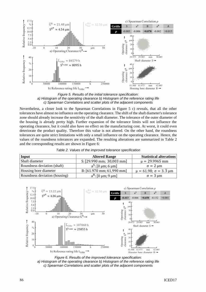
and the corresponding results are shown in Figure 6:
Table 2. Values of the improved tolerance specification
Input Altered Range Statistical alterations
Shaft diameter S: [29.990 mm; 30,003 mm] µ = 29.9965 mm
Roundness deviation (shaft) aS: [0 µm; 6 µm] σ = 2 µm
Housing bore diameter B: [61.970 mm; 61,990 mm] µ = 61.98; σ = 3. 3̅ µm
Roundness deviation (housing) aB: [0 µm; 9 µm] σ = 3 µm
Figure 6. Results of the improved tolerance specification: a) Histogram of the operating clearance b) Histogram of the reference rating life
c) Spearman Correlations and scatter plots of the adjacent components
86
ICED17
As expected, the interference fit on the shaft as well as the mean shift of the housing bore diameter has
led to a decrease of the operating clearance. The restriction of housing bore diameter has also caused a
decrease of the sample standard deviation. However, the decrease is relatively small because of the
increased sensitivity of the operating clearance in reference to the other deviations (cf. Figure 5 c)).
Despite of this, most of the operating clearances are still positive guaranteeing the mountability of the
bearings. Moreover, the very restrictive roundness tolerances of the shaft and housing boring can be
expanded.
Nevertheless, a raise of the sample standard deviation of the fatigue life occurred. A reason for this is
the discontinuity of the relationship between the operating clearance and the fatigue life. Yet, the mean
fatigue life has been increased tremendously.
Summing up the results for this use case, an improved tolerance specification of the bearing seats can
be achieved by employing the herein presented method, though the solution is still not optimal. Further
adjustments would be necessary. Instead of performing those adjustments manually an optimization
algorithm could be used such as the Particle Swarm Optimization proposed by Walter, Spruegel and
Wartzack (2014).
5 CONCLUSION AND OUTLOOK
In this article a method was presented which can be used for the analysis of the tolerance specification
of the bearing seats for cylindrical roller bearings. The considered functional key characteristics are the
operating clearance as well as the fatigue life. In the evaluation of the operating clearance not only the
geometric deviations but also the deformations of the bearing components due to tight fits and thermal
expansion are regarded. The operating clearances are determined using a discrete geometry
representation in conjunction with contact detection algorithms. Thereafter the results of the operating
clearance are coupled with the calculation of the reference rating life according to ISO/TS 16281. The
method also proposes some statistical analysis in order to assist an engineering designer when altering
the tolerance specification of a bearing seat. The application of the method was shown for a simple use
case afterwards. For the use case an increase of the fatigue life with decreasing operating clearances
could be observed. This provokes tight fits for the bearing seats.
However, an engineering designer should always consider a system at a whole. Therefore further
extensions of the method are necessary like the consideration of additional key characteristics such as
the vibrational behavior. What is more, not only cylindrical roller bearings but different bearings types
should be considered. This implies a 3D treatment of the bearings, also allowing the consideration of a
tilting due to mounting as well as a misalignment between two bearing seats on a shaft respectively in a
housing.
REFERENCES
Aschenbrenner, A. and Wartzack, S. (2016), “A Concept for the Consideration of Dimensional and Geometrical
Deviations in the Evaluation of the Internal Clearance of Roller Bearings”, Procedia CIRP, Vol. 43, pp.
256-261. http://dx.doi.org/10.1016/j.procir.2016.02.003
Colosimo, B. M., Moroni, G., Petro, S. and Semeraro, Q. (2004), “Manufacturing Signature of Turned Circular
Profiles”, Manufacturing, Modelling, Management and Control, Vol. 15 No. 2, pp. 1–6.
Dantan, J.-Y., Gayton, N., Etienne, A. and Quereshi, A. J. (2012), “Mathematical issues in mechanical tolerance
analysis”, 13. Colloque National AIP PRIMECA, Le Mont-Dore/France, March 2012, pp. 1–12.
https://hal.archives-ouvertes.fr/hal-00756539
De Mul, J., Kalker, J. J. and Frederiksson, B. (1986), “The Contact Between Arbitrarily Curved Bodies of Finite
Dimensions”, Journal of Tribology, Vol. 108 No. 1, pp. 140–148. http://dx.doi.org/10.1115/1.3261134
DIN 5402-1 (2014): Rolling bearings – Pars of rolling bearings – Part 1: Cylindrical rollers, Deutsches Institut
für Normung, Berlin/Germany.
DIN 7190-1 (2013): Interference fits – Part 1: Calculation and design rules, Deutsches Institut für Normung,
Berlin/Germany.
Eschmann, P., Hasbargen, L. and Weigand K. (1985), Ball and Roller Bearings – Theory, Design and
Application, John Wiley and Sons, Chichester, New York, Brisbane, Toronto and Singapore.
Guo, W., Cao, H., He, Z. and Yang, L. (2015), “Fatigue Life Analysis of Rolling Bearings Based on Quasistatic
Modeling”, Shock and Vibration, Vol. 2015 No. 15, pp. 1–10. http://dx.doi.org/10.1155/2015/982350
Harsha, S.P., Sandeep, H. and Prakash, R. (2003): “The effect of speed of balanced rotor on nonlinear vibrations
associated with ball bearings”, International Journal of Mechanical Sciences, Vol. 24, pp. 725–740.
http://dx.doi.org/10.1016/S0020-7403(03)00064-X
87
ICED17
Havel, J. and Herout, A. (2010), “Yet faster ray-triangle intersection (using SSE4)”, IEEE transactions on
visualization and computer graphics, Vol. 16 No. 3, pp. 434–438.
http://dx.doi.org/10.1109/TVCG.2009.73
Hoffenson, S., Dagman, R. and Söderberg, R. (2013), “Tolerance Specification Optimization for Economic and
Ecological Sustainability”, In: Abramovici, M., Stark, R. (Ed.), Smart Product Engineering, Springer,
Berling/Germany, Hamburg/Germany, pp. 865–874. http://dx.doi.org/10.1007/978-3-642-30817-8_85
ISO 492 (2014), Rolling bearings – Radial bearings – Geometrical product specifications (GPS) and tolerance
values, International Organization for Standardization, Geneva/Switzerland.
ISO 5753-1 (2009): Rolling Bearings – Internal clearance – Part 1: Radial internal clearance for radial
bearings, International Organization for Standardization, Geneva/Switzerland.
ISO/TR 1281-1 (2008), Rolling bearings – Explanatory nodes on ISO 281 – Part 1: Basic dynamic load rating
and basic rating life, International Organization for Standardization, Geneva/Switzerland.
ISO/TS 16281 (2008), Rolling bearings – Methods for calculating the modified reference rating life for
universally loaded bearings, International Organization for Standardization, Geneva/Switzerland.
Kockara, S., Halic, T., Bayrak C. and Rowe, R. A. (2009), “Contact Detection Algorihms”, Journal of
Computers, Vol. 4 No. 10, pp. 1053–1063.
Mitrović, R. M., Atanasovska, I. D., Soldat N. D. and Momčilović, D. B. (2015), “Effects of Operation
Temperature on Thermal Expansion and Main Parameters of Radial Ball Bearings”, Thermal Science, Vol.
19 No. 5, pp. 1835–1844. http://dx.doi.org/10.2298/TSCI141223091M
Oswald, F. B., Zaretsky, E. V. and Poplawski, J. V. (2009), “Interference-Fit Life Factors for Roller Bearings”,
Tribology Transactions, Vol. 52 No. 4, pp. 415–426. http://dx.doi.org/10.1080/10402000802687890
Oswald, F. B., Zaretsky, E. V. and Poplawski, J. V. (2012), “Effect of Internal Clearance on Load Distribution
and Life of Radially Loaded Ball and Roller Bearings”, Tribology Transactions, Vol. 55 No. 2, pp. 245–
265. http://dx.doi.org/10.1080/10402004.2011.639050
Saltelli, A., Chan, K. and Scott, E. M. (2000), Sensitivity Analysis, Wiley, Chichester/England.
Schaeffler Technologies GmbH & Co. KG (2012), Rolling bearing – Ball bearings, Roller bearings, Needle
roller bearings, Track rollers, Bearings for screw drives, Insert bearings/housing units, Bearing housings,
Accessories.
Schleich, B. and Wartzack, S. (2013), “How to determine the influence of geometric deviations on elastic
deformations and the structural performance?”, Proceedings of the Institution of Mechanical Engineers,
Part B: Journal of Engineering Manufacture, Vol. 227 No. 5, pp. 754–764.
http://dx.doi.org/10.1177/0954405412468994
Schleich, B. and Wartzack, S. (2014), “A discrete geometry approach for tolerance analysis of mechanism”,
Mechanism and Machine Theory, Vol. 77, pp. 148–163.
http://dx.doi.org/10.1016/j.mechmachtheory.2014.02.013
Schmid, S. R., Hamrock B. J. and Jacobson, B. O. (2014), Fundamentals of Machine Elements, CRC press,
Hoboken/USA.
SKF Group (2013), Rolling bearings.
Thornton, A. C. (1999), “Variation Risk Management Using Modeling and Simulation”, Journal of Mechanical
Design, Vol. 121 No. 2, pp. 297-304. http://dx.doi.org/10.1115/1.2829457
Walter, M. S. J., Spruegel, T. C. and Wartzack, S. (2015), “Least Cost Tolerance Allocation for Systems with
Time-variant Deviations”, Procedia CIRP, Vol. 27, pp. 1–9. http://dx.doi.org/10.1016/j.procir.2015.04.035
Wardle F. P. (1988), “Vibration Forces Produced by Waviness of the Rolling Surfaces of Thrust Loaded Ball
Bearings Part 1: Theory”, Journal of Mechanical Engineering Science, Vol. 202 No. 5, pp. 305–312.
Ye Z.-h. and Wang L.-q. (2015), “Optimization analysis on assembly interference of cylindrical roller bearings”,
Advances in Mechanical Engineering, Vol. 7 No. 7, pp. 1–13.
http://dx.doi.org/10.1177/1687814015593868
Zhang M., Anwer, N., Mathieu, L. and Zhao, H. B. (2011), “A discrete geometry framework for geometrical
product specifications”, 21th CIRP Design Conference, Daejoen/South Korea, March 2011, pp. 142–148.
ACKNOWLEDGEMENTS
The authors like to thank the Industrial Collective Research (IGF), a subgroup of the Consortium of
Industrial Research Associations 'Otto von Guericke' e.V. (AiF), and the Research Association for Drive
Technology (FVA) for their support. The authors also like to thank the anonymous referees for their
helpful comments, which helped to improve the article.
Funding
The research project IGF 18417 N "Roller Bearing Tolerances: Basics for the revision of the tolerance
design of roller bearings" is supported by the Federal Ministry for Economic Affairs and Energy on the
basis of a decision by the German Bundestag.
88