Embed Size (px)
Citation preview
British Journal of Ophthalmology, 1979, 63, 215-220
A new method of estimating the depthof the anterior chamberREDMOND J. H. SMITHFrom Moorfields Eye Hospital and the Western Ophthalmic Hospital, London
SUMMARY A new method of estimating the depth of the anterior chamber with an accuracy ofapproximately 0 1 mm is described. The estimate is made with a conventional Haag-Streit 900 slitlamp without any extra attachments.
Measurement of the depth of the anterior chambercan be carried out under clinical conditions by meansof the attachment to the Haag-Streit 900 slit lamp,which is based on the method of Jaeger (1952).Photographic measurements can be made as de-scribed by Heim (1941), Bleeker (1960, 1961), andBrown (1973), and ultrasonic techniques can alsobe used.An ingenious optical device embodying 2 pairs of
apertures, each providing independently focusingdouble pencils-I pair to be coincident on thecorneal endothelium and 1 on the lens capsule-was described by Stenstrom (1953) as a modificationof a device invented by Lindstedt (1916). All thesemethods, however, require the use of specialattachments to the slit lamp, with or withoutphotographic techniques in addition.The method to be described uses the standard
model Haag-Streit 900 slit lamp alone; no extraapparatus is required.
Technique
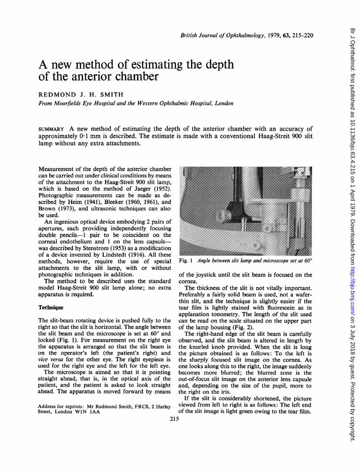
The slit-beam rotating device is pushed fully to theright so that the slit is horizontal. The angle betweenthe slit beam and the microscope is set at 600 andlocked (Fig. 1). For measurement on the right eyethe apparatus is arranged so that the slit beam ison the operator's left (the patient's right) andvice versa for the other eye. The right eyepiece isused for the right eye and the left for the left eye.The microscope is aimed so that it is pointing
straight ahead, that is, in the optical axis of thepatient, and the patient is asked to look straightahead. The apparatus is moved forward by means
Address for reprints: Mr Redmond Smith, FRCS, 2 HarleyStreet, London WIN IAA
Fig. 1 Angle between slit lamp and microscope set at 600
of the joystick until the slit beam is focused on thecornea.The thickness of the slit is not vitally important.
Preferably a fairly solid beam is used, not a wafer-thin slit, and the technique is slightly easier if thetear film is lightly stained with fluorescein as inapplanation tonometry. The length of the slit usedcan be read on the scale situated on the upper partof the lamp housing (Fig. 2).The right-hand edge of the slit beam is carefully
observed, and the slit beam is altered in length bythe knurled knob provided. When the slit is longthe picture obtained is as follows: To the left isthe sharply focused slit image on the cornea. Asone looks along this to the right, the image suddenlybecomes more blurred; the blurred zone is theout-of-focus slit image on the anterior lens capsuleand, depending on the size of the pupil, more tothe right on the iris.
If the slit is considerably shortened, the pictureviewed from left to right is as follows: The left endof the slit image is light green owing to the tear film.
215
on 3 July 2018 by guest. Protected by copyright.
http://bjo.bmj.com
/B
r J Ophthalm
ol: first published as 10.1136/bjo.63.4.215 on 1 April 1979. D
ownloaded from
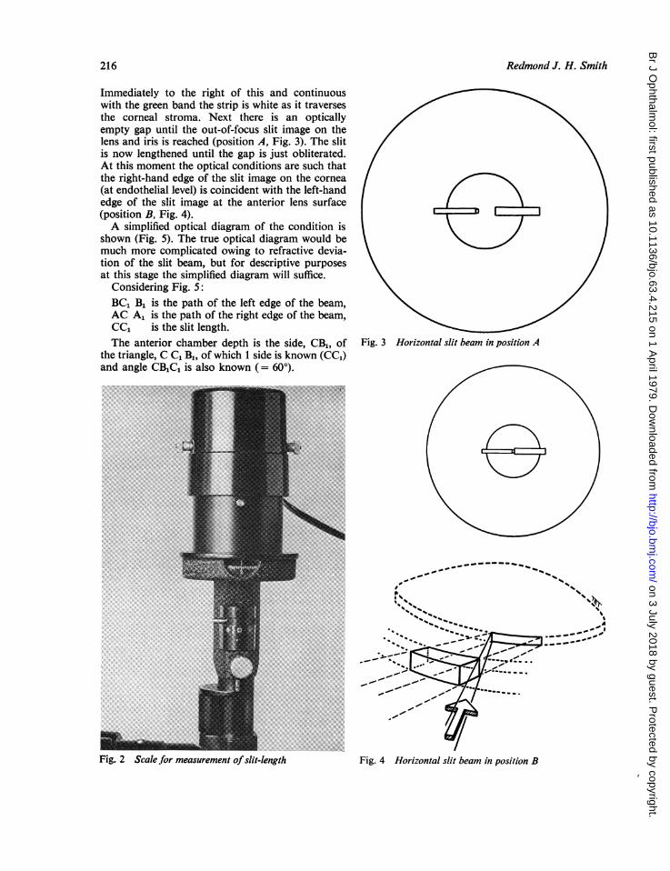
Immediately to the right of this and continuouswith the green band the strip is white as it traversesthe corneal stroma. Next there is an opticallyempty gap until the out-of-focus slit image on thelens and iris is reached (position A, Fig. 3). The slitis now lengthened until the gap is just obliterated.At this moment the optical conditions are such thatthe right-hand edge of the slit image on the cornea(at endothelial level) is coincident with the left-handedge of the slit image at the anterior lens surface(position B, Fig. 4).A simplified optical diagram of the condition is
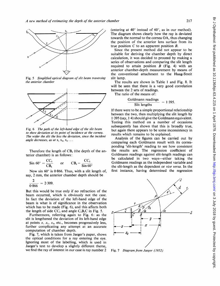
shown (Fig. 5). The true optical diagram would bemuch more complicated owing to refractive devia-tion of the slit beam, but for descriptive purposesat this stage the simplified diagram will suffice.
Considering Fig. 5:BC1 B1 is the path of the left edge of the beam,AC A1 is the path of the right edge of the beam,CC1 is the slit length.The anterior chamber depth is the side, CB1, of Fig. 3 Horizontal slit beam in position A
the triangle, C C1 B1, of which 1 side is known (CC1)and angle CB1CL is also known (= 600).
..~~~~~~~~~~~~~~~~~~~~~~~~~~. ..........
...~~ ~ ~ ~... .......
.~~~~~~~~~~~~~~~~~~..i
_~~~~~~~~,-
M ~........... ~7''--
_~ ~~~ ~~ ~ ~~ ~~~~~~~~~~~~~~~~~~~,' -
_ .. : '" /Fig 2 Scl for mesuemn ofsi-eghFg oiona ltba npsto
Redmond J. H. Smith216
Fig. 2 Scalefor measurement ofslit-length Fig. 4 Horizontal slit beam in position B
on 3 July 2018 by guest. Protected by copyright.
http://bjo.bmj.com
/B
r J Ophthalm
ol: first published as 10.1136/bjo.63.4.215 on 1 April 1979. D
ownloaded from
A new method of estimating the depth of the anterior chamber
Fig. 5 Simplified optical diagram of slit beam traversingthe anterior chamber
Fig. 6 The path oJ the left-hand edge of the slit beamto show deviation at its point of incidence at the cornea.The wider the slit the less the deviation, since the incidentangle decreases, as at x, X1, X2 ...
Therefore the length of CB1 (the depth of the an-terior chamber) is as follows:
Sin 60° = CCcCB,
cc,or CB1 Sin 600
Now sin 60° is 0 866. Thus, with a slit length of,say, 2 mm, the anterior chamber depth should be
2 = 2 309.0-866
But this would be true only if no refraction of thebeam occurred, which is obviously not the case.In fact the deviation of the left-hand edge of thebeam is what is of significance in the observationwhich has to be made (Fig. 6), and this affects boththe length of side CC1 and angle CIBIC in Fig. 5.
Furthermore, referring again to Fig. 6: as theslit is lengthened the deviation of its left-hand edgeat points x, x1, x2, etc., becomes progressively less,further complicating any attempt at an accuratecomputation of chamber depth.
Fig. 7, which is taken from Jaeger's paper, showsthe optical conditions for a ray entering the eye.Ignoring most of the labelling, which is used inJaeger's text to develop a slightly different theme,we find the ray of interest in our case is ray number 2
(entering at 40° instead of 600, as in our method).The diagram shows clearly how the ray is deviatedtowards the normal to the cornea OA, thus changingthe position of the anterior lens surface from itstrue position C to an apparent position B.
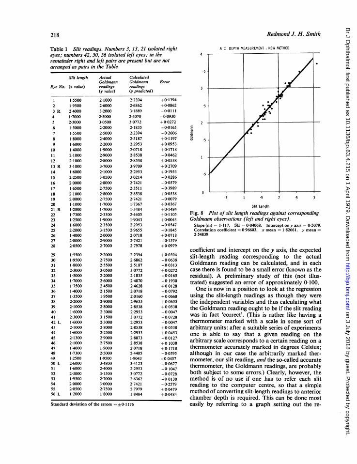
Since the present method did not appear to besuitable for deriving the chamber depth by directcalculation, it was decided to proceed by making aseries of observations and comparing the slit lengthrequired to attain position B (Fig. 4) with ananterior chamber-depth measurement by means ofthe conventional attachment to the Haag-Streitslit lamp.The results are shown in Table 1 and Fig. 8. It
will be seen that there is a very good correlationbetween the 2 sets of readings.The ratio of the means of:
Goldmann readingsSlit lengths
1395.
If there were to be a simple proportional relationshipbetween the two, then multiplying the slit length by1-395 (say, 1-4) should give the Goldmann equivalent.Testing this method on a number of occasionssubsequently has shown that this is broadly true,but again there appears to be some inconsistency inresults which remains to be explained.
Analysis of the figures can be carried out bycomparing each Goldmann result with its corres-ponding 'slit-length' reading to see how consistentthe results are. The regression coefficient ofGoldmann readings against slit-length readings canbe calculated in two ways-either taking theGoldmann readings as the independent variable andthe slit-length as the dependent or vice versa. In thefirst instance, having determined the regression
Fig. 7 Diagram from Jaeger (1952)
217
on 3 July 2018 by guest. Protected by copyright.
http://bjo.bmj.com
/B
r J Ophthalm
ol: first published as 10.1136/bjo.63.4.215 on 1 April 1979. D
ownloaded from
218 Redmond
Table 1 Slit readings. Numbers 3, 13, 21 isolated right A C DEPTH MEASUREMENT: NEW METHODeyes; numbers 42, 50, 56 isolated left eyes; in the 4 -
remainder right alnd left pairs are present but are notarranged as pairs in the Tableremainderrigtandleft pirs are preset but are no
Slit length
Eye No. (x value)
ActualGoldmannreadings(y value)
CalculatedGoldmannreadings(y predicted)
Error
J. H. Smith
1 1-5500 2-1000 2-2394 +0-1394 * .2 19500 2-6000 2-6862 +0-0862 53 R 2-4000 3-2000 3-1889 -0-0111 04 1-7000 25000 2-4070 -0-09305 2-3000 3 0500 3-0772 +0-0272 26 15000 2-2000 2-1835 -0-0165 ' 07 15500 25000 2-2394 -0-2606 E
8 1-8000 2-4000 2-5187 +0-1197 .59 1-6000 2-2000 2-2953 +0-095310 1-4000 19000 2-0718 +0-17181 1 2-1000 2-9000 2-8538 -0-0462 112 2-1000 2-8000 2-8538 +0 053813 R 3-1000 3 7000 39709 +0270914 1-6000 2-1000 2-2953 +0 1953 515 2-2500 3 0500 3-0214 -0-028616 2-0000 2-8000 2-7421 - 0057917 1-6500 27500 2-3511 -0-398918 2-1000 2-8000 2-8538 +0 0538 D19 2-0000 27500 2-7421 -0 0079 5 1 5 2 .5 320 1-1000 1-7000 1-7367 +0-0367 Slit Length21 R 1-2000 1-7000 1-3484 +0-148422 1-7300 2-3300 24405 ±01105 Fig. 8 Plot of slit length readings against corresponding23 1-2500 19000 19043 +0-0043 Goldmann observations (left and right eyes).24 1-6000 2-3500 2-2953 -0 0547 Slope (m) = 1-117. SE = 0-04068. Intercept ony axis = 0-5079.25 2-2000 3-1500 2-9655 -0-1845 Correlation coefficient = 0-96603. x mean = 1-82661. y mean =26 1-4000 2-0000 2-0718 +0-0718 2-5483927 2-0000 2-9000 2-7421 -0-157928 2-0500 2-7000 2-7978 +0-0979
coefficient and intercept on the y axis, the expected29 15500 2-2000 2-2394 +00394 slit-length reading corresponding to the actual30 1-9500 2-7500 2-6862 - 0-063831 1-8000 2-5500 2-5187 -0-0313 Goldmann reading can be calculated, and In each32 2-3000 3 0500 3-0772 +0-0272 case there is found to be a small error (known as the33 1-5000 2-2000 2-1835 -0-0165 residual). A preliminary study of this (not illus-34 1-7000 2-6000 2-4070 -0-1930 trated) suggested an error of approximately 0-100.35 1-7500 2-4500 2-4628 +0-012836 1-4000 2-1500 2-0718 -0-0792 One iS now in a position to look at the regression37 1-3500 1-9500 2-0160 +0-0660 using the slit-length readings as though they were38 2-2000 2-9000 2-9655 +0 0655 the independent variables and thus calculating what39 2-1000 2-8000 2-8538 +0-0538 the Goldmann reading ought to be if the slit reading40 1-6000 2-3000 2-2953 -0-004741 2-3000 3-1500 3-0772 - 0-0728 was in fact 'correct'. (This iS rather like having a42 L 1-6000 2-3000 2-2953 -0-0047 thermometer marked with a scale in some sort of43 2-1000 2-8000 2-8538 +0-0538 arbitrary units: after a suitable series of experiments44 1-6000 2-2500 2-2953 +0-0453 one is able to say that a given reading on the45 2-1300 2-9000 2-8873 -0-012746 2-1000 2-7500 2-8538 +0-1038 arbitrary scale corresponds to a certain reading on a47 1-4000 1-9000 2-0718 +0-1718 thermometer accurately marked in degrees Celsius;48 1-7300 25000 2-4405 - 00595 although in our case the arbitrarily marked ther-49 1 2500 1 9500 1-9043 -0-0457 mometer, our slit reading, and the so-called accurate50 L 2-6000 3-4800 3-4123 - 0°0677 thermometer, the Goldmann readings, are probably51 1-6000 2-4000 2-2953 -0-104752 2-3000 3-1500 3-0772 -0-0728 both subject to some errors.) Clearly, however, the53 1-9500 2-7000 2-6362 -0-0138 method is of no use if one has to refer each slit54 2-0000 3-0000 2-7421 - 0-2579 reading to the computer centre, so that a simple55 2-0500 2-7500 2 7979 + 0 0479 method of converting slit-length readings to anterior56 L 1-2000 1-8000 1-8484 1 0-0484 chamber depth is required. This can be done mostStandard deviation of the errors =0-1176 easily by referring to a graph setting out the re-
- - s
on 3 July 2018 by guest. Protected by copyright.
http://bjo.bmj.com
/B
r J Ophthalm
ol: first published as 10.1136/bjo.63.4.215 on 1 April 1979. D
ownloaded from
A new method of estimating the depth of the anterior chamber
gression line of slit length against Goldmann readingsor by calculation using this formula:
y = mx + b where m is the slope (regressioncoefficient) and b is the intercepton the y axis.
Substituting these figures we have:
Calculated Goldmann reading = (1-17 x slitreading + 0 5079).
Using no. 1 in the Table as an example, we find thatthe slit length found (1 5500) gives a calculatedGoldmann reading of 2-2394, whereas the Goldmannreading actually found was 2 100, an error of 0-1394.Similarly, in no. 19, where the slit-length reading is2-0000, the Goldmann reading can be calculated as2-7421, whereas the reading actually found was2-7500, an error of -0 0079.
In short, therefore, it appears that the slit-lengthmethod consists in measuring the slit length requiredfor coincidence as described, multiplying the resultby 1-117, and adding 05079, or, simplifying, G =
SL x 1-1 + 0 5, an extremely simple and quickcalculation.The error to be expected in such a method can
be approximately determined by calculating thestandard deviation of the errors listed in the right-hand column in the Table. This comes out at+0-1176.There remains, however, the anomaly that as
slit-length and Goldmann readings approach zerothey should, theoretically, reach it at the same time.In other words the regression line in Fig. 8 oughtto pass through zero, which it does not.
In fact the relationship between slit-length andchamber depth is probably not properly representedby a straight line owing to the influence of the cornealrefraction varying at different slit lengths, as shownon Fig. 6. Dr Swinscow (personal communication)feels that it is possible to envisage a shallow curvepassing through most of the points which wouldunite a position near 0 with the outermost dot inthe right-hand corner, but that a straight lineprovides a good approximation within a range thatexcludes the top right-hand dot.The final conclusion, therefore, has to be that an
exact and simple relationship cannot be demon-strated over the whole range, but for slit lengths of1 to 2-5 mm the simple ratio quoted earlier (1-4) issufficiently near the truth to be of clinical utility.In practice this is of great clinical value for thefollowing reasons. Slit lengths of below 1 mmcannot be used because they are not marked on theinstrument, and slit lengths in excess of 2-5 mmimply a chamber depth of at least 3 0 mm, as shownon the graph.
In summary, it seems reasonable to claim thatthe technique provides a quick method of estimatingchamber depths between the range of 1-4 and3*0 mm, a useful range in many clinical conditions.
Discussion
A quick and simple method of measuring anteriorchamber depth is especially useful in closed-angleglaucoma, where the diagnosis may depend to somedegree on recognition of a shallow chamber and theability to measure it.Although mydriatic glaucoma is rare, it is helpful
to have a record of the chamber depth beforeinstillation of a mydriatic, particularly, when aclinical estimate by simple observation has givenrise to suspicion. A chamber depth of 2 mm or lessshould be regarded with considerable anxiety,especially if mydriasis is contemplated.
Variations in chamber depth at various times, forexample, before and after mydriatics or miotics, aresometimes of interest and may be surprisinglylarge. Similarly, variations in depth between the 2eyes may also be found, especially where there areunequal degrees of maturity of cataract. An eyewith a mature cataractous lens may show either amuch shallower or, alternatively, a much deeperchamber than the fellow eye, since the lens mayswell or shrink when cataractous.Measurement of anterior chamber depth is also
valuable before considering implantation of anacrylic lens in the anterior chamber.A final point may be of some interest: the
coincidence method of measuring chamber depthmeasurement tends to give very similar values forthe right and left eye, and it will be noted that thetechnique is symmetrical, the incident beam beingdirected in each eye from the temporal side and theaxis of observation being approximately along theoptic axis. In the Haag-Streit depth-measuringapparatus the incident beam enters along theoptical axis, but the observation axis is not sym-metrical for the 2 eyes, being from the nasal side inthe case of the right eye and the temporal for the left.
I have detected a slight, but definite tendency forthe anterior chamber depth estimate on the left eyeby the Haag-Streit method to be slightly higher(by 0-023 mm). This has also been reported byLowe (1968). It seems unlikely that the left chamberis in fact deeper than the right, and the coincidencemethod described does not indicate that this is so,since by this method the difference is 0003. Hence itmay be that this new method of measuring chamberdepth is in fact slightly more accurate than theGoldmann system in some respects, not of coursein providing an actual measurement of depth, which
219
on 3 July 2018 by guest. Protected by copyright.
http://bjo.bmj.com
/B
r J Ophthalm
ol: first published as 10.1136/bjo.63.4.215 on 1 April 1979. D
ownloaded from
Redmond J. H. Smith
it is unable to do, but in so far as it can confirm that2 chambers are of exactly equal depth.
My thanks are due to the Statistical Department at theInstitute of Ophthalmology, and to Dr T. D. V. Swinscowfor valuable advice and to Miss J. Quaife for secretarialassistance.
References
Bleeker, G. M. (1960). Serial recording of the depth of theanterior chamber. Archives of Ophthalmology, 63, 821-830.
Bleeker, G. M. (1961). Evaluation of three methods ofrecording the anterior chamber depth of the eye. Archivesof Ophthalmology, 65, 369-374.
Brown, N. (1973). Quantitative Slit-Image Photography ofthe anterior chamber. Transactions of the Ophthalmological
Societies of the United Kingdom, 93, 277-286.Heim, M. (1941). Photographische Bestimmung der Tiefeund des Volumens der menschlichen Vorderkammer.Ophthalmologica, 102, 193-220.
Jaeger, W. (1952). Tiegenmessung der menschlichen Vorder-kammer mit plan parallelen plattern. (Zusatzgerat zurSpaltlampe). Albrecht v. Graefes Archiv fur Ophthalmo-logie, vereinigt mit Archivfur Augenheilkunde, 153, 120-131.
Lindstedt, F. (1916). Uber die messung der Tiefe der vorderenAugenkammer mittels eines neuen, fur klinischenGebrauch bestimmten Instruments. Archiv fur Augen-heilkunde, 80, 104-167.
Lowe, R. F. (1968). Time-amplitude ultrasonography forocular biometry. American Journal of Ophthalmology, 66,913-918.
Stenstrom, S. (1953). An apparatus for the measurement ofthe depth of the anterior chamber based on the principleof Lindstedt. Acta Ophthalmologica, 31, 265-270.
220
on 3 July 2018 by guest. Protected by copyright.
http://bjo.bmj.com
/B
r J Ophthalm
ol: first published as 10.1136/bjo.63.4.215 on 1 April 1979. D
ownloaded from