Embed Size (px)
DESCRIPTION
A Methodology for Assessing the Remaining Life ofElectronic Products.
Citation preview
International Journal of Performability Engineering, Vol. 2, No. 4, October 2006, pp. 383 - 395
© RAMS Consultants Printed in India
*Communicating author email: [email protected] 383
A Methodology for Assessing the Remaining Life of Electronic Products
S. MATHEW1, P. RODGERS
2, V. EVELOY
2,
N. VICHARE1, and M. PECHT
1,*
1CALCE Electronic Products and Systems Center, University of Maryland, College Park,
MD, USA 2The Petroleum Institute, Abu Dhabi, United Arab Emirates
(Received on January 25, 2006)
Abstract: Remaining life assessment is an estimate of the reliability of a product in its
life cycle application environment based on health monitoring and prognostics analyses.
This paper reviews remaining life assessment methodologies that are currently employed
for engineering products, and discusses their potential applicability to electronic systems.
Based on this review, a generic ‘Health Status Assessment’ methodology for assessing the
remaining life of electronic products is derived. The methodology is applied to an
electronic circuit board used in a space application.
Key Words: Health and usage monitoring, remaining life, life cycle, prognostics health
management, FEMA, FEMMA, stress and damage modeling, electronics reliability
1. Introduction
The reliability of an electronic product is defined as its ability to perform its intended
functions for a specific period of time, in its life cycle application environment.
Electronic products can experience a range of load conditions during their lifetime, from
manufacturing, assembly, testing, storage, handling, transportation, to operation.
Depending on the application and environment in which the product is used, the loads can
vary from benign to destructive. Over time, such loads can cause accumulated damage to
the printed circuit board, electronic components and component-to-board interconnects,
and affect the reliability of the product [1].
Traditional electronics reliability prediction methods utilize field data, test data, stress
and damage models, and reliability handbooks. These methods generally do not
accurately account for the life cycle environment of electronic products [2]. This arises
from either fundamental flaws in the reliability assessment methodologies used [3], or
uncertainties in the product life cycle [4]. These limitations can be overcome through the
use of health monitoring, which is a proactive approach of estimating the reliability of a
product. Health monitoring is a process of observing and recording the extent of
deviation or degradation from an expected normal operating condition [5]. Health
monitoring techniques typically combine sensing, recording and interpretation of
environmental, operational, usage and performance-related parameters indicative of the
products health [2]. Applications of health monitoring are typically classified as
diagnostics, prognostics and life consumption monitoring.
_____________________________________
S. Mathew, P. Rodgers, V. Eveloy,
N. Vichare, and M. Pecht
384
Diagnostic systems monitor the current operating state of health of the product to
identify the potential causes of failure [5], and can provide efficient fault detection and
identification, thereby assisting in maintaining the effectiveness of the equipment through
timely repair actions. Prognostic systems monitor the faults or precursors to failure, and
predict the time to failure, or numbers of operational cycles to failure, induced by a
monitored fault [5]. This approach provides real time reliability estimates for a product in
its actual application conditions. Life consumption monitoring is a health monitoring
method, which quantifies product degradation in terms of the amount of its life consumed
[6]. The life consumption monitoring process involves the continuous or periodic
collection, and interpretation of, the product’s life cycle environment. The remaining life
estimate of the product is an output of the life consumption monitoring method.
Estimating the remaining life of electronic products that has been already deployed in
the field presents a unique challenge. For such products, the life cycle data available is
not the data obtained by a pre-planned monitoring process, but through a routine general
data collection event such as maintenance activities. In most such cases, actual life cycle
environmental data may not have been monitored. A remaining life assessment estimates
the ability of the electronic products to meet the required performance specifications in its
life cycle application environment for the remaining service life of the product [7]. Only a
limited number of studies [7], [8], [9] have been published on remaining life assessment
methodologies for electronic products. These studies have estimated the remaining life of
electronic hardware based on virtual assessment, physical analyses and testing techniques.
However, no rationale or guidelines were provided for the selection of the techniques used
and their applicability. This paper addresses this weakness by presenting a methodology
for conducting remaining life assessment of electronic hardware already deployed in the
field. Before developing such a methodology, remaining life assessment strategies
applied to other engineering hardware are examined.
Remaining life studies for engineering products, excluding electronic assemblies,
have focused on mechanical products and civil structures. Mechanical products include
heavy equipments like gas and steam turbines, boilers, refinery heater tubes, industrial
furnaces, pressure vessels, pressure vessel nozzles, components of petrochemical plants,
liquid natural gas (LNG) plants, fossil power plants, power plants and ship turbines
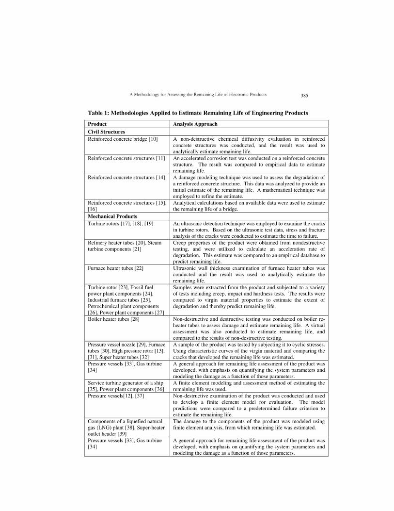
generators. The civil structures include reinforced concrete structures and bridges. Table
1 summarizes the techniques used by such studies to assess the remaining life of
mechanical products and civil structures.
Remaining life assessment techniques used for civil structures and mechanical
products can be categorized into three main groups: physical analysis (non-destructive and
destructive), damage modeling (analytical and finite element), and testing. Most of these
studies have employed a combination of the three techniques to determine the remaining
life of a product. Many of the techniques used in the above studies could be applicable to
electronic products deployed in the field. Some of these techniques are applicable (e.g.,
destructive testing of sample) only in cases where additional equivalent samples are
available for possible destructive testing. Some are applicable (e.g., sample extraction)
only on large mechanical systems where small samples harvested for testing does not
impair the structural integrity of the system. These techniques were taken into
consideration in this paper to develop a generic methodology for remaining life assessment
of electronic products. The proposed methodology is described in the following section, and
applied to the remaining life assessment of an electronic circuit board.
A Methodology for Assessing the Remaining Life of Electronic Products 385
Table 1: Methodologies Applied to Estimate Remaining Life of Engineering Products
Product Analysis Approach
Civil Structures
Reinforced concrete bridge [10] A non-destructive chemical diffusivity evaluation in reinforced
concrete structures was conducted, and the result was used to
analytically estimate remaining life.
Reinforced concrete structures [11] An accelerated corrosion test was conducted on a reinforced concrete
structure. The result was compared to empirical data to estimate
remaining life.
Reinforced concrete structures [14] A damage modeling technique was used to assess the degradation of
a reinforced concrete structure. This data was analyzed to provide an
initial estimate of the remaining life. A mathematical technique was
employed to refine the estimate.
Reinforced concrete structures [15],
[16]
Analytical calculations based on available data were used to estimate
the remaining life of a bridge.
Mechanical Products
Turbine rotors [17], [18], [19] An ultrasonic detection technique was employed to examine the cracks
in turbine rotors. Based on the ultrasonic test data, stress and fracture
analysis of the cracks were conducted to estimate the time to failure.
Refinery heater tubes [20], Steam
turbine components [21]
Creep properties of the product were obtained from nondestructive
testing, and were utilized to calculate an acceleration rate of
degradation. This estimate was compared to an empirical database to
predict remaining life.
Furnace heater tubes [22] Ultrasonic wall thickness examination of furnace heater tubes was
conducted and the result was used to analytically estimate the
remaining life.
Turbine rotor [23], Fossil fuel
power plant components [24],
Industrial furnace tubes [25],
Petrochemical plant components
[26], Power plant components [27]
Samples were extracted from the product and subjected to a variety
of tests including creep, impact and hardness tests. The results were
compared to virgin material properties to estimate the extent of
degradation and thereby predict remaining life.
Boiler heater tubes [28] Non-destructive and destructive testing was conducted on boiler re-
heater tubes to assess damage and estimate remaining life. A virtual
assessment was also conducted to estimate remaining life, and
compared to the results of non-destructive testing.
Pressure vessel nozzle [29], Furnace
tubes [30], High pressure rotor [13],
[31], Super heater tubes [32]
A sample of the product was tested by subjecting it to cyclic stresses.
Using characteristic curves of the virgin material and comparing the
cracks that developed the remaining life was estimated.
Pressure vessels [33], Gas turbine
[34]
A general approach for remaining life assessment of the product was
developed, with emphasis on quantifying the system parameters and
modeling the damage as a function of those parameters.
Service turbine generator of a ship
[35], Power plant components [36]
A finite element modeling and assessment method of estimating the
remaining life was used.
Pressure vessels[12], [37] Non-destructive examination of the product was conducted and used
to develop a finite element model for evaluation. The model
predictions were compared to a predetermined failure criterion to
estimate the remaining life.
Components of a liquefied natural
gas (LNG) plant [38], Super-heater
outlet header [39]
The damage to the components of the product was modeled using
finite element analysis, from which remaining life was estimated.
Pressure vessels [33], Gas turbine
[34]
A general approach for remaining life assessment of the product was
developed, with emphasis on quantifying the system parameters and
modeling the damage as a function of those parameters.
S. Mathew, P. Rodgers, V. Eveloy,
N. Vichare, and M. Pecht
386
2. Health Status Assessment Methodology
The process of determining the remaining life of a product already deployed in the
field is analogous to determining the status of the product’s health at that given moment.
Hence the methodology proposed here is termed as ‘Health Status Assessment
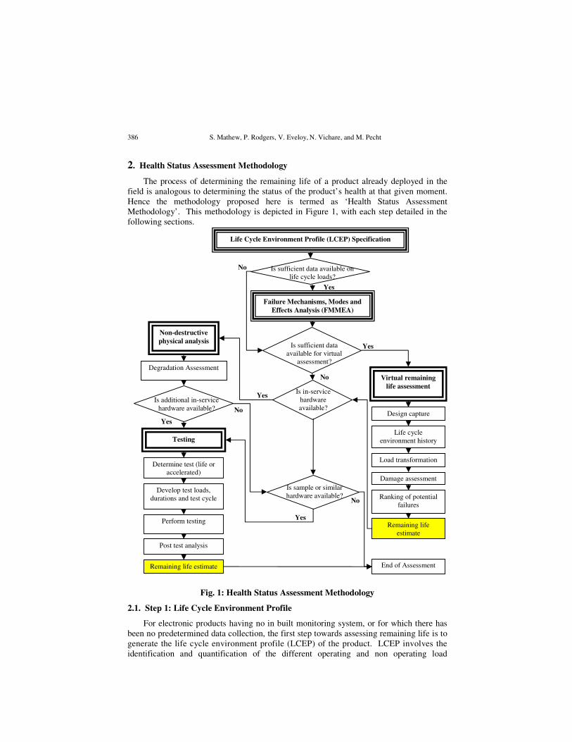
Methodology’. This methodology is depicted in Figure 1, with each step detailed in the
following sections.
Fig. 1: Health Status Assessment Methodology
2.1. Step 1: Life Cycle Environment Profile
For electronic products having no in built monitoring system, or for which there has
been no predetermined data collection, the first step towards assessing remaining life is to
generate the life cycle environment profile (LCEP) of the product. LCEP involves the
identification and quantification of the different operating and non operating load
Is additional in-service
hardware available?
Virtual remaining
life assessment
Life Cycle Environment Profile (LCEP) Specification
Failure Mechanisms, Modes and
Effects Analysis (FMMEA)
Yes
Is sufficient data available on
life cycle loads?
Is in-service
hardware
available?
Is sufficient data
available for virtual
assessment?
Design capture
Life cycle
environment history
Damage assessment
Load transformation
Ranking of potential
failures
Remaining life
estimate
End of Assessment
Determine test (life or
accelerated)
Remaining life estimate
Post test analysis
Perform testing
Develop test loads,
durations and test cycle
Testing
Degradation Assessment
Non-destructive
physical analysis
Is sample or similar
hardware available?
No
Yes
No
Yes
No
No
Yes
Yes
A Methodology for Assessing the Remaining Life of Electronic Products 387
conditions of the products. The data to be collected involve the physical data, functional
data and the life cycle environment data. Physical data includes geometrical information
about the printed circuit board (length, width, thickness, number of layers, percent
metallization, layer material etc.) and the architecture of the components mounted on the
board (part types, dimensions, mounting styles, material, lead material, position of the
component on the board etc.). The functional data includes the duty cycles, power cycles,
and duration of operation. The life cycle environment data includes the life cycle loads,
life cycle phases, operating conditions, and areas of application. A complete and accurate
collection of data is vital to the accuracy of remaining life estimation.
It is important to assess the sufficiency of the data generated to move to step 2. If the
life cycle data is limited, it will not be possible to proceed with step 2. In such a case the
availability of sufficient data for a virtual assessment would help continue the remaining
life assessment process as shown in Figure 1.
2.2. Step 2: Failure Mechanisms, Modes and Effects Analysis
If sufficient data has been generated in the LCEP analysis, step 1, then failure
mechanisms, modes and effects analysis (FMMEA) for the products can be conducted.
FMMEA is an extension of the traditional failure mechanisms and effects analysis
(FMEA), and is described in [40]. This methodology involves identifying the failure
mechanisms and models for all potential failure modes, and prioritizing them according to
their potential damage impact. The prioritization process utilizes information related to
the application conditions, duration of application, active stresses and potential failure
mechanisms. The first step in FMMEA is to define the products and the components on
the products. This is followed by identifying the potential failure modes and causes, the
associated applicable failure mechanisms and appropriate failure models. The identified
failure mechanisms are ranked according to their impact on the product’s reliability in its
life cycle environment conditions.
As indicated in Figure 1, if there is sufficient data about the material properties and
geometry of the board and components, the analysis process progresses to a virtual
remaining life assessment. However, if the data is insufficient for virtual remaining life
assessment, a non-destructive physical analysis of an in-service products is performed to
estimate remaining life. If no in-service product is available, a sample or similar product
can be tested to estimate the remaining life of the products under assessment.
2.3. Step 3: Virtual Remaining Life Assessment
The virtual remaining life assessment is based on a physics-of-failure stress and
damage accumulation analysis. This analysis involves using the material properties,
geometry and measured life cycle loads of the product, to assess the dominant failure
mechanisms. Based on a load-stress simulation, the physics-of-failure damage models
give an estimation of the accumulated damage for the product in its life cycle
environment. The virtual remaining life process consists of the following steps: design
capture, life cycle loading history characterization, load transformation, damage
assessment, and ranking of potential failures for remaining life estimation [41].
Design capture involves identifying the components on the board, recording their
dimensions and position on the board, the board dimensions, and material properties of
the board, component and interconnects. This data is prescribed into the physics-of-
failure based software. Materials include substrate, encapsulants, underfills, leads and
S. Mathew, P. Rodgers, V. Eveloy,
N. Vichare, and M. Pecht
388
platings, solders, conductive adhesives, socket materials, and the makeup of the printed
wiring board (e.g., resin system, plating, embedded passives).
Characterization of the life cycle load history involves identifying and recording
significant life cycle loads and simplifying them for assessment. Examples of
environmental loads required for life cycle loading characterization include temperature
extremes and mean temperature, frequency of the temperature cycles, vibration, shock and
electrical loads. The magnitude of these loads should be accompanied with details of their
rate of change and duration of exposure to these loads.
The life cycle loads’ profiles are converted into a form that can be used as input to the
software program for modeling. The load transformation process utilizes the
characterized loading conditions to estimate the effect of these loads on the circuit card.
The software takes the environment and architecture input and produces the stress fields
(e.g., temperature, displacement, and curvature). Thermal stresses are usually associated
with mechanical (structural) failures (e.g., ductile rupture, brittle fracture, creep, stress
relaxation, thermal shock, stress, and corrosion).
The damage assessment is conducted using a failure model incorporating both a stress
model and a damage model. Stress models correlate the environmental and operational
loads, package architecture, and material properties to stress, strain and energy
distributions within the components and the solder joint interconnects. The damage
models are used to determine the number of cycles to failure. In the damage assessment
step, the damage for each part is defined in terms of damage ratio (DR), which is the ratio
of the number of cycles applied to the number of cycles (or other equivalent units) it can
survive.
The ranking of potential failures involves ranking the components in decreasing order
of damage ratios. Once the failure potentials are ranked, the remaining life of the
component for which the damage ratio is highest is estimated. The remaining life is given
by subtracting the damage ratio from the damage criterion (equal to 1) and dividing that
value by the damage ratio per future life cycle. The remaining life of the electronic
product is equal to the remaining life of the component with the highest damage ratio.
If an in-service product is available for assessment, the remaining life assessment
process moves on to the fourth step of non-destructive physical analysis. If no in-service
product is available, then the availability of a similar circuit card that has been in use or a
sample circuit card with similar construction but not used in the field, should be
determined. As shown in Figure 1, if samples or similar circuit cards are not available,
the remaining life estimate obtained from the virtual remaining life assessment is the best
possible estimate.
2.4. Step 4: Non-Destructive Physical Analysis
Non-destructive physical analysis of the product involves the assessment of
degradation of the printed circuit board, the components on the board, the solder joint
interconnects and the metal traces on the board. Non-destructive analysis uses techniques
such as optical inspection, ultrasonic testing, and dye penetration test, to identify and
investigate signs of degradation. Optical inspection of the components and solder joint
interconnections reveals visible signs of damage. Cracks and voids affect the reliability of
the component, which in turn affects the remaining life of the electronic circuit board.
The components are inspected to determine the possible presence of visible physical
damage to the components. The circuit board and the metal traces on the board are also
A Methodology for Assessing the Remaining Life of Electronic Products 389
inspected for any visible damage. Characterization of small solder samples taken from the
solder joint interconnections, and comparison of the results to virgin solder properties will
indicate the amount of degradation at the solder joints. The degradation can be expressed
in terms of percentage of characteristic or virgin properties or in terms of damage ratio.
From the estimated amount of degradation, the remaining life of the product can be
predicted.
After non-destructive physical analysis, if additional in-service product is available
for evaluation, the remaining life assessment process moves to the fifth and final step,
namely testing. In case additional in-service product is not available, a similar circuit card
that has been in use or a sample circuit card with similar construction but not used in the
field, can be tested. As illustrated in Figure 1, if neither a similar circuit card or sample
circuit card is available, the remaining life assessment is terminated.
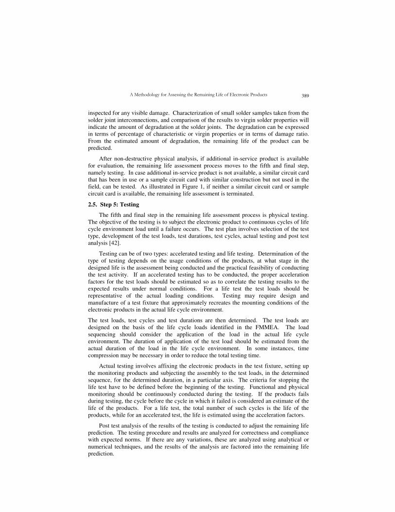
2.5. Step 5: Testing
The fifth and final step in the remaining life assessment process is physical testing.
The objective of the testing is to subject the electronic product to continuous cycles of life
cycle environment load until a failure occurs. The test plan involves selection of the test
type, development of the test loads, test durations, test cycles, actual testing and post test
analysis [42].
Testing can be of two types: accelerated testing and life testing. Determination of the
type of testing depends on the usage conditions of the products, at what stage in the
designed life is the assessment being conducted and the practical feasibility of conducting
the test activity. If an accelerated testing has to be conducted, the proper acceleration
factors for the test loads should be estimated so as to correlate the testing results to the
expected results under normal conditions. For a life test the test loads should be
representative of the actual loading conditions. Testing may require design and
manufacture of a test fixture that approximately recreates the mounting conditions of the
electronic products in the actual life cycle environment.
The test loads, test cycles and test durations are then determined. The test loads are
designed on the basis of the life cycle loads identified in the FMMEA. The load
sequencing should consider the application of the load in the actual life cycle
environment. The duration of application of the test load should be estimated from the
actual duration of the load in the life cycle environment. In some instances, time
compression may be necessary in order to reduce the total testing time.
Actual testing involves affixing the electronic products in the test fixture, setting up
the monitoring products and subjecting the assembly to the test loads, in the determined
sequence, for the determined duration, in a particular axis. The criteria for stopping the
life test have to be defined before the beginning of the testing. Functional and physical
monitoring should be continuously conducted during the testing. If the products fails
during testing, the cycle before the cycle in which it failed is considered an estimate of the
life of the products. For a life test, the total number of such cycles is the life of the
products, while for an accelerated test, the life is estimated using the acceleration factors.
Post test analysis of the results of the testing is conducted to adjust the remaining life
prediction. The testing procedure and results are analyzed for correctness and compliance
with expected norms. If there are any variations, these are analyzed using analytical or
numerical techniques, and the results of the analysis are factored into the remaining life
prediction.
S. Mathew, P. Rodgers, V. Eveloy,
N. Vichare, and M. Pecht
390
In case remaining life estimates from virtual remaining life assessment, as well as
non-destructive analysis and testing are available, the result of the testing process should
be used for future course of action. The virtual remaining life assessment will provide
accurate estimates only for the failure mechanisms that have been modeled. Non-
destructive physical analysis will provide an estimate of the amount of degradation in a
component or at a particular site. The amount and rate of future damage may vary
depending on the future operating conditions. Testing usually provides the best remaining
life estimate since the products is actually subjected to its life cycle loads till a failure
occurs. This result can be used as the basis for future operation and maintenance strategy
for an electronic products unit similar to the products under review.
3. Application of the Health Status Assessment Methodology to an Electronic
Circuit Board
The health status assessment methodology was utilized to assess the remaining life of
an electronic circuit board that is part of the integrated electronic assembly (IEA) of one
of the space shuttle's solid rocket boosters (SRB). The board is a single sided FR4-based
printed circuit card, incorporating resistors, capacitors, diodes, transistors, transformer
assemblies, connector, and optocouplers. All but four transistors and two transformers are
insertion mount components. The four transistors are mounted on the aluminum brackets
that are part of the aluminum wedge frame riveted to the board. The two transformers are
affixed to the center of the board with screws. The C-shaped aluminum frame on the
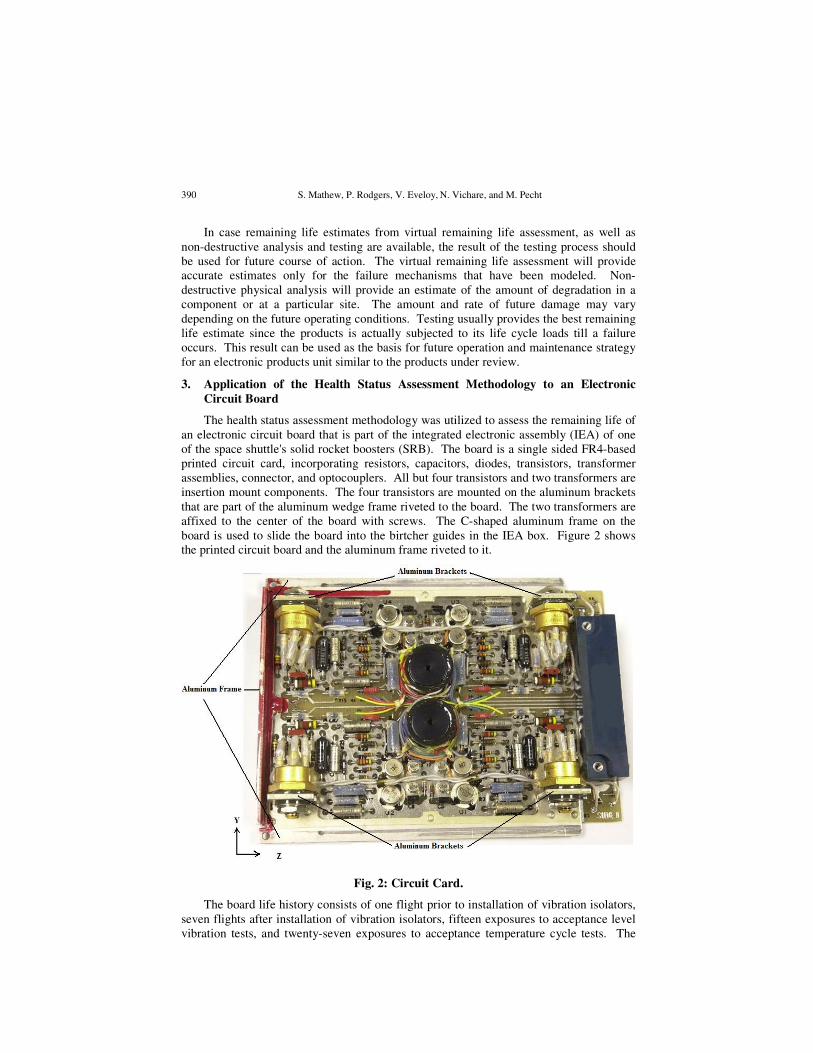
board is used to slide the board into the birtcher guides in the IEA box. Figure 2 shows
the printed circuit board and the aluminum frame riveted to it.
Fig. 2: Circuit Card.
The board life history consists of one flight prior to installation of vibration isolators,
seven flights after installation of vibration isolators, fifteen exposures to acceptance level
vibration tests, and twenty-seven exposures to acceptance temperature cycle tests. The
A Methodology for Assessing the Remaining Life of Electronic Products 391
detailed random vibration, shock and temperature cycling load data for each life cycle
condition were provided by NASA. In addition to the actual circuit card, a sample
engineering card, which was physically and functionally identical to the actual card, was
available for assessment.
Employing the health status assessment methodology presented in this paper, the life
cycle environment profile (LCEP) was generated by gathering the geometry and material
details, life history and life load information of the board. A FMMEA indicated that the
effect of random vibrations, shock and temperature cycling on the component-to-board
solder joint interconnects was a potential reliability concern. The FMMEA also identified
the effect of out-of-plane shock load on the components and 90° bend of aluminum
bracket structure on the board as a potential concern.
Based on this FMMEA and available data, a virtual remaining life assessment using
CalcePWA software was conducted with focus on the component-to-board solder joint
interconnects. Using the stress and damage models for thermal and vibration fatigue, the
damage caused by each type of life cycle load condition was calculated. This analysis
indicated that the effect of the life cycle loading conditions on solder joint interconnect
reliability was not as severe as anticipated. It was estimated that the circuit card could
survive forty additional launch missions before any failure would occur.
Analytical and finite element methods were used to determine the effect of the shock
loads experienced during the board life on the aluminum brackets. It was found that the
aluminum brackets of the circuit card had lost significant life, and that damage
accumulation occurred at the bend of the bracket due to shock loading. Since each launch
mission, including the vibration acceptance test, lasted for only eight minutes, it was
decided to conduct a life test to verify the results of the virtual remaining life assessment.
It was determined from the virtual assessment that the random vibrations during preflight
acceptance test and during the actual flight and the shock on water impact were the most
damaging loading conditions that the circuit card had experienced. Therefore, the life test
conducted involved simulating the vibration and shock loads representative of the actual
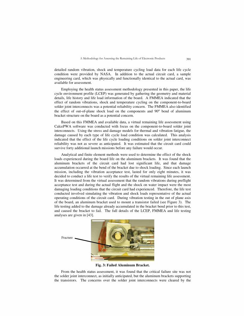
operating conditions of the circuit card. During vibration testing in the out of plane axis
of the board, an aluminum bracket used to mount a transistor failed (see Figure 3). The
life testing added to the damage already accumulated in the bracket bend prior to this test,
and caused the bracket to fail. The full details of the LCEP, FMMEA and life testing
analyses are given in [43].
Fig. 3: Failed Aluminum Bracket.
From the health status assessment, it was found that the critical failure site was not
the solder joint interconnect, as initially anticipated, but the aluminum brackets supporting
the transistors. The concerns over the solder joint interconnects were cleared by the
Fracture
S. Mathew, P. Rodgers, V. Eveloy,
N. Vichare, and M. Pecht
392
virtual assessment predictions. In addition, the life test proved that the shock in the out of
plane axis of the board would cause lasting damage to the aluminum bracket. In
conclusion, the health status assessment methodology implemented for assessing the
remaining life of the circuit card identified and experimentally isolated the critical failure
on the circuit card. Such analysis could be applied to other electronic hardware that are
already deployed in the field.
4. Conclusions
To date, remaining life assessment methodologies for non-electronic engineering
products already deployed in the field have combined physical analysis (non-destructive
and destructive), damage modeling (analytical and finite element), and testing. In this
paper, a health status assessment methodology was proposed for assessing the remaining
life of electronic products already deployed in the field. The methodology utilizes life
cycle environment specification (LCEP), failure mechanisms, modes and effects analysis
(FMMEA), non-destructive physical analysis, virtual remaining life assessment, and
testing, to estimate remaining life. The methodology was successfully applied to an
electronic circuit board used in a space application.
References
[1] Dasgupta, A., The Physics-of-Failure Approach at the University of Maryland for
the Development of Reliable Electronics, Proceedings of the third
International
Conference on Thermal and Mechanical Simulation in (Micro)Electronics
(EuroSimE), pp. 10–17, Paris, France, April, 2002.
[2] Vichare, N., V. Eveloy, P. Rodgers, and M. G. Pecht, In situ Temperature
Measurement of a Notebook Computer - A Case Study in Health and Usage
Monitoring of Electronics, IEEE Transactions on Device and Materials Reliability,
Vol. 4, No. 4, pp. 658-663, 2004.
[3] Lall, P., M. Pecht, and E. Hakim, Influence of Temperature on Microelectronics
and System Reliability, New York, CRC Press, 1997.
[4] Ramakrishnan, A., D. Das, and M. G. Pecht, The IEEE Standards on Reliability
Program and Reliability Prediction Methods for Electronic Equipment,
Microelectronics Reliability, Vol. 42, pp. 1259-1266, 2002.
[5] Vichare, N., P. Rodgers, M. Azarian, and M. G. Pecht, Application of Health
Monitoring to Product Take-back Decisions, Proceedings of the Joint International
Congress and Exhibition - Electronics Goes Green 2004, pp. 945-951, Berlin,
Germany, September 6-8, 2004.
[6] Ramakrishnan, A., and M. G. Pecht, Implementing a Life Consumption Monitoring
Process for Electronic Product, IEEE Transactions on Components and Packaging
Technologies, Vol. 26, No. 3, pp. 625-634, 2003.
[7] Valentin, R., M. Osterman, and B. Newman, Remaining Life Assessment of Aging
Electronics in Avionic Applications, Proceedings of the Annual Reliability and
Maintainability Symposium, pp. 313-318, Tampa Florida, U.S.A., January 27-30,
2003.
[8] Shetty, V., D. Das, M. Pecht, D. Hiemstra, and S. Martin, Remaining Life
Assessment of Shuttle Remote Manipulator System end Effector, Proceedings of the
22nd Space Simulation Conference, Ellicott City, MD, USA, October 21-23, 2002.
[9] McCluskey, F. P., Y. D. Kweon, H. J. Lee, J. W. Kim, and H. S. Jeon, Method for
Assessing Remaining Life in Electronic Assemblies, Microelectronics Reliability,
Vol. 40, pp. 293-306, 2000.
A Methodology for Assessing the Remaining Life of Electronic Products 393
[10] Liang, M. T., K. L. Wang, and C. H. Liang, Service Life Prediction of Reinforced
Concrete Structures, Journal of Cement and Concrete Research, Vol. 29, No. 9, pp.
1411-1418, 1999.
[11] Torres-Acosta, Andres A., and M. Martinez-Madrid, Residual Life of Corroding
Reinforced Concrete Structures in Marine Environment, Journal of Materials in
Civil Engineering, Vol. 15, No. 4, pp. 344 -353, 2003.
[12] Duvenhage, G., and J. Wannenburg, Remaining Life Analysis of a Pressure Vessel
Subjected to Cyclic Loads based on Fracture Mechanics, International Journal of
Fatigue, Vol. 17, No. 7, pp. 477-483, 1995.
[13] Cheruvu, N. S., and L. R. Malmfeldt, Metallurgical Characterization of High
Pressure Rotor for Remaining Service Life Assessment after 26 Years of Service,
American Society of Mechanical Engineers, Joint ASME/IEEE Power Generation
Conference., Miami Beach, FL, USA, 1987.
[14] Rao, B. K., M. B. Anoop, N. Lakshmanan, S. Gopalakrishnan and T. V. S. R. Appa
Rao, Risk-based Remaining Life Assessment of Corrosion Affected Reinforced
Concrete Structural Members, Journal of Structural Engineering, Vol. 31, No. 1,
pp. 51-64, 2004.
[15] Yang, S. I. , D. M. Frangopol, and L. C. Neves, Service Life Prediction of
Structural Systems using Lifetime Functions with Emphasis on Bridges, Journal of
Reliability Engineering and System Safety, Vol. 86, No. 1, pp. 39 -51, 2004.
[16] Hong, H.P., Assessment of Reliability of Aging Reinforced Concrete Structures,
Journal of Structural Engineering, Vol. 126, No. 12, pp. 1458-1465, Dec, 2000.
[17] Caccialupi, A., R. Crudeli, G. P. Fazio, F. Porro, M. Santoro, and M. Zannoni,
Approach to Residual Life Assessment of Large Steam Turbine Components,
International Journal of Pressure Vessels and Piping, Vol. 59, pp. 241- 258, 1994.
[18] Nottingham, L. D., and C. T. Alley, Turbine Rotor Remaining Life Assessment,
American Society of Mechanical Engineers, Power Division (Publication) PWR,
Vol. 3, pp. 179-185, 1988.
[19] Matsubara, M., and A. Nitta, Remaining Life Assessment of Actual Steam Turbine
Rotors using the Ultrasonic Method, American Society of Mechanical Engineers,
Pressure Vessels and Piping Division (Publication), PVP, Vol. 303, pp. 49-55,
1995.
[20] Bell, D. C., A. J. Richard, L. C. Feltz, I. Le May, T. L. Da Silveira, and C. H.
Vianna, Criteria for Evaluation of Damage and Remaining Life in Reformer
Furnace Tubes, International Journal of Pressure Vessels and Piping, Vol. 66, No.
1, pp. 233-241, 1996.
[21] Vishwanathan, R., Estimation of Remaining Life of Boiler Parts, American Society
of Mechanical Engineers, Pressure Vessels and Piping Division (Publication), PVP,
Vol. 98-1, pp. 183, 1985.
[22] Moss, C. J., and M. R. Finlay, Remaining Life Assessment of Furnace Heater
Tubes, American Society of Mechanical Engineers, Pressure Vessels and Piping
Division (Publication), PVP, Vol. 332, pp. 23-33, 1996.
[23] Swaminathan, V. P., R. Viswanathan, C. P. Clark, Material Property Studies of
Two High-pressure Turbine Rotors for Remaining Life Assessment, Transactions of
the ASME, Journal of Engineering Materials and Technology, Vol. 116, No. 1, pp.
19-26, 1994.
[24] Wu, Y. H., C. H. Wu, and H. C. Lai, Life Assessment Activities of Fossil Fuel
Power Plant in the Republic of China, International Journal of Pressure Vessels and
Piping, Vol. 59, pp. 185-195, 1994.
S. Mathew, P. Rodgers, V. Eveloy,
N. Vichare, and M. Pecht
394
[25] Dai, S.H., A Study of Residual Life Prediction for Pressurized Tubes of an
Industrial Furnace Operated at Elevated Temperature by Using the Method of
Extrema of Fuzzy Functions, International Journal of Pressure Vessels and Piping,
Vol. 63, pp. 199-204, 1995.
[26] Sivaprasad, S., J. Swaminathan, Y. N. Tiwary, P. K. Roy, and R. Singh, Remaining
Life Assessment of Service Exposed Reactor and Distillation Column Materials of a
Petrochemical Plant, Journal of Engineering Failure Analysis, Vol. 10, No. 3, pp.
275-289, 2003.
[27] Shor, S.W.W., A. O. Call, R. L. Loos, M. R. Bozo, and T. W. Vanvick, Criteria for
Economical Remaining Life Assessment, American Society of Mechanical
Engineers, Joint ASME/IEEE Power Generation Conference., Miami Beach, FL,
October 19-23, 1987.
[28] Vishwanathan, R., S. R. Paterson, H. Grunloh, and S. Gehl, Life Assessment of
Superheater / Reheater Tubes in Fossil Boilers, Journal of Pressure Vessel
Technology, Transactions of the ASME, Vol. 116, No. 1, pp. 116, 1994.
[29] Gigilio, M., and L. Vergani, Life Prediction of Pressure Vessel Nozzles,
International Journal of Pressure Vessels and Piping, Vol. 63, pp. 199-204, 1995.
[30] Kim, D. S., and H. E. Mead, Remaining Life Assessment of Refinery Heater Tubes,
American Society of Mechanical Engineers, Pressure Vessels and Piping Division
(Publication), PVP, Vol. 388, pp. 361-366, 1999.
[31] Schlottner, G., and R. E. Seeley, Estimation of Remaining Life of High
Temperature Steam Turbine Components, American Society of Mechanical
Engineers, Pressure Vessels and Piping Division (Publication), PVP, Vol. 98-1, pp.
35-44, 1985.
[32] Grunloh, H. J., and R. Hellner, Remaining Life Assessment of Superheater Tubing
by Post Service Creep Rupture Testing, American Society of Mechanical
Engineers, Pressure Vessel and Piping Conference, PVP Vol. 22, San Diego, CA,
USA, 1987.
[33] Jaske, C. E., Benefits of Remaining Life Assessment, Chemical Engineering
Progress, Vol. 83, No. 4, pp. 3746, 1987.
[34] Liu, Z., V. Volovoi, and D. N. Marvis, Probabilistic Remaining Creep Life
Assessment for Gas Turbine Components under Varying Operating Conditions,
American Inst. Aeronautics and Astronautics, 43rd Structures, Structural,
Dynamics and Materials Conference, Vol. 1, pp. 587-597, Denver, CO, USA, April
22-25, 2002.
[35] Byron, J. D., S. R. Paterson, R. R. Proctor, and T. J. Feiereisen, Assessment of
Remaining Useful Life of Ships Service Turbine Generator Steam Chests, Naval
Engineers Journal, Vol. 98, No. 3, pp. 95 -106, 1986.
[36] Ohtani, R., Questions and Solutions on the Method of Remaining Life Evaluation of
Structural Materials in High Temperature Power Plants, Transactions of the Japan
Society of Mechanical Engineers, Part A, Vol. 59, No. 565, pp. 2019-2026, 1993.
[37] Yee, R.K., Fitness for Service and Remaining Useful Life Assessment of a Steam
Drum, American Society of Mechanical Engineers, Pressure Vessels and Piping
Division (Publication), PVP, Vol. 459, pp. 41-46, 2003.
[38] Taillin, A. G., X. Sukamto, and D. L. Bagnoli, Remaining Life- Risk Ranking Study
for an LNG Plant, American Society of Mechanical Engineers, Pressure Vessels
and Piping Division (Publication), PVP, Vol. 336, pp. 139-148, 1996.
[39] Rosario, D. A., P. C. Riccardella, L. H. Bisbee, M. E. Luttrell, S. Nelson, A. D.
Eastman, and M. D. Rogers, Remaining Life Assessment of a Secondary
A Methodology for Assessing the Remaining Life of Electronic Products 395
Superheater Outlet Header, American Society of Mechanical Engineers, Pressure
Vessels and Piping Division (Publication), PVP, Vol. 303, pp. 291-299, 1995.
[40] Ganesan, S., V. Eveloy, D. Das, and M. G. Pecht, Identification and Utilization of
Failure Mechanisms to Enhance FMEA and FMECA, Proceedings of the IEEE
Workshop on Accelerated Stress Testing & Reliability (ASTR), Austin, Texas,
October 3-5, 2005.
[41] Cunningham, J., R. Valentin, C. Hillman, A. Dasgupta, and M. Osterman, A
Demonstration of Virtual Qualification for the Design of Electronic Products,
ESTECH 2001, IEST, Phoenix, AZ, USA, April, 2001.
[42] Upadhyayula, K., and A. Dasgupta, Guidelines for Physics-of-failure based
Accelerated Stress Testing, Proceedings of the Annual Reliability and
Maintainability Symposium, Anaheim, California, USA, January 19-22, 1998.
[43] Mathew, S., D. Das, M. Osterman, and M. Pecht, M., Prognostics Assessment of
Aluminum Support Structure on a Printed Circuit Board, accepted for publication
in the Transactions of the ASME, Journal of Electronic Packaging.
Sony Mathew received the B.E. in Mechanical Engineering, MBA in Business
Administration both from Pune University, India, and M.S. in Mechanical Engineering
from the University of Maryland, College Park, USA. He is currently working as a
Faculty Research Assistant at the CALCE Electronic Products and System Center,
University of Maryland. His current research interests include both failure analysis of
electronic products, and electronics reliability.
Peter Rodgers, biography given in IJPE, Vol. 2, No. 2, 2006 on page 160.
Valérie Eveloy holds a Ph.D. in Mechanical Engineering from Dublin City University,
Ireland, and a M.Sc. in physical engineering from the National Institute of Applied
Science (INSA), France. She has been involved in the packaging, thermal management
and reliability of electronic equipment for eleven years. She is currently an assistant
research professor at The Petroleum Institute, United Arab Emirates. She was previously
a research scientist at the CALCE Electronic Products and Systems Center at the
University of Maryland, College Park; Nokia Research Center, Finland; and Electronics
Thermal Management Ltd, Ireland. Her research interests have included the cooling of
electronic equipment, electrical overstress failures in integrated circuits, the transition to
lead-free electronics, computational fluid dynamics, and biomedical human health
monitoring. She has authored or co-authored over 45 conference and refereed journal
publications. Dr. Eveloy is a member of several international conference program
committees focused on electronics reliability and thermal phenomena in electronic
systems. She was Physics-of-Failure track chair at the 2005 IEEE Workshop on
Accelerated Stress Testing & Reliability (ASTR).
Nikhil Vichare, biography given in IJPE, Vol. 2, No. 2, 2006 on page 160.
Michael G. Pecht, biography given in IJPE, Vol. 2, No. 2, 2006 on page 161.


![A Methodology for Assessing the Remaining Life of ...A finite element modeling and assessment method of estimating the remaining life was used. Pressure vessels[12], [37] Non-destructive](https://img.pdfslide.net/doc/110x75/5ff1cd81341352650319a5ba/a-methodology-for-assessing-the-remaining-life-of-a-finite-element-modeling.jpg)