Embed Size (px)
Citation preview
AngewandteChemie
Zuschriften
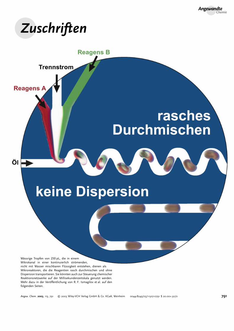
W�ssrige Tropfen von 250 pL, die in einemMikrokanal in einer kontinuierlich str�menden,nicht mit Wasser mischbaren Fl ssigkeit entstehen, dienen alsMikroreaktoren, die die Reagentien rasch durchmischen und ohneDispersion transportieren. Sie k�nnten auch zur Steuerung chemischerReaktionsnetzwerke auf der Millisekundenzeitskala genutzt werden.Mehr dazu in der Ver�ffentlichung von R. F. Ismagilov et al. auf denfolgenden Seiten.
791Angew. Chem. 2003, 115, 791 � 2003 Wiley-VCH Verlag GmbH & Co. KGaA, Weinheim 0044-8249/03/11507-0791 $ 20.00+.50/0
High-Throughput Measurements
A Microfluidic System for Controlling ReactionNetworks in Time**
Helen Song, Joshua D. Tice, and Rustem F. Ismagilov*
We present here a microfluidic system that may be used tocontrol networks of many chemical reactions on the milli-second scale. It allows to control when each reaction begins,for how long each reaction evolves before it is separated orcombined with other reactions, and when each reaction isanalyzed or quenched. The system uses flow of fluids tolinearly transform space (length of capillaries) into time(reaction time). For a chemical reaction in an open system thistransformation is simple and well known: A solution ofreagent A and a solution of reagent B are injected as steadystreams into a microfluidic channel at initial point d= 0 wherethe reaction between them begins (t= 0). As the reactionmixture is transported by the fluid stream at a constantvelocity U, every spatial point d corresponds to a time point t,the reaction time, where t= d/U. If such a system isimplemented, interactions of multiple chemical reactions intime could be controlled simply by creating a network ofconverging and diverging channels carrying reaction mixtures,and varying flow velocities to adjust reaction and interactiontimes. If the reactions are accompanied by an optical signal(e.g. changes in fluorescence or absorption), time-resolvedmeasurements of the reactions in the entire network could beobtained from a single spatially resolved optical image.
Networks of microfluidic channels[1–3] are especiallyattractive for this distance-to-time transformation becausethey can be easily fabricated and used to manipulate smallvolumes of reagents; they are becoming essential for chemicaland biological analysis and synthesis.[1–3] Flow in microfluidicdevices is laminar; it occurs at low values of the Reynoldsnumber,Re (~ 0.01–100).Re is defined as lU1/m, where l [m] isthe diameter of the capillary,U [ms�1] the velocity of the flow,1 [kgm�3] the density, and m [kgm�1 s�1] the viscosity of thefluid.[4] This laminar flow makes it difficult to implement thedistance-to-time transformation in microfluidic devices for
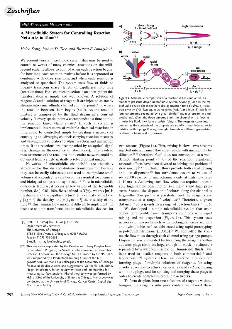
two reasons (Figure 1a). First, mixing is slow—two streamsinjected into a channel flow side-by-side with mixing only bydiffusion,[4–6] therefore d= 0 does not correspond to a well-defined starting point (t= 0) of the reaction. Significantresearch efforts have been devoted to solving this problem ofslow mixing.[2,3, 7] Turbulent flows provide both rapid mixingand low dispersion,[8] but turbulence occurs at values ofRe> 2000 reached in microchannels only at high flow rates(~ 10 ms�1). Achieving such flow velocities requires undesir-ably high sample consumption (~ 1 mLs�1) and high pres-sures. Second, the dispersion of solutes along the channel islarge—the flow profile is parabolic, and the reagents aretransported at a range of velocities.[4] Therefore, a givendistance d corresponds to a range of reaction times t=d/U.
We developed a simple microfluidic system that over-comes both problems—it transports solutions with rapidmixing and no dispersion (Figure 1b). This system usesnetworks of microchannels with rectangular cross sectionsand hydrophobic surfaces fabricated using rapid prototypingin polydimethylsiloxane (PDMS).[9] We controlled the volu-metric flow rates through each channel using syringe pumps.Dispersion was eliminated by localizing the reagents withinaqueous plugs (droplets large enough to block the channel)separated by a water-immiscible oil. Immiscible fluids havebeen used to localize reagents in both commercial[10] andlaboratory[11–13] systems. Here we describe methods forforming plugs of multiple solutions of reagents, for usingchaotic advection to achieve especially rapid (~ 2 ms) mixingwithin the plugs, and for splitting and merging these plugs inorder to create complex microfluidic networks.
To form droplets from two solutions of reagents withoutbringing the reagents into prior contact we flowed these
Figure 1. Schematic comparison of a reaction A+B conducted in astandard pressure-driven microfluidic system device (a) and in the mi-crofluidic device described here (b). a) Reaction time t¼6 d/U. b) Reac-tion time t=d/U. Two aqueous reagents (red, A and blue, B) can formlaminar streams separated by a gray “divider” aqueous stream in a mi-crochannel. When the three streams enter the channel with a flowingimmiscible fluid, they form droplets (plugs). The reagents come intocontact as the contents of the droplets are rapidly mixed. Internal recir-culation within plugs flowing through channels of different geometriesis shown schematically by arrows.
[*] Prof. R. F. Ismagilov, H. Song, J. D. TiceDepartment of ChemistryThe University of Chicago5735 S. Ellis Avenue, Chicago, IL 60637 (USA)Fax: (+1)773-702-0805E-mail: [email protected]
[**] This work was supported by the Camille and Henry Dreyfus NewFaculty Award Program, the Searle Scholars Program, an award fromResearch Corporation, the Chicago MRSEC funded by the NSF. H.S.was supported by a Predoctoral Training Grant of the NIH(GM08720). We thank our colleagues at the University of Chicagofor invaluable discussions and suggestions. We thank Prof. SidneyNagel, in addition, for an equipment loan and Ian Hawkins formeasuring surface tensions. Photolithography was performed byH.S. at MAL of the University of Illinois at Chicago. Microscopy wasconducted at the University of Chicago Cancer Center Digital LightMicroscopy Facility.
Zuschriften
792 � 2003 Wiley-VCH Verlag GmbH & Co. KGaA, Weinheim 0044-8249/03/11507-0792 $ 20.00+.50/0 Angew. Chem. 2003, 115, Nr. 7
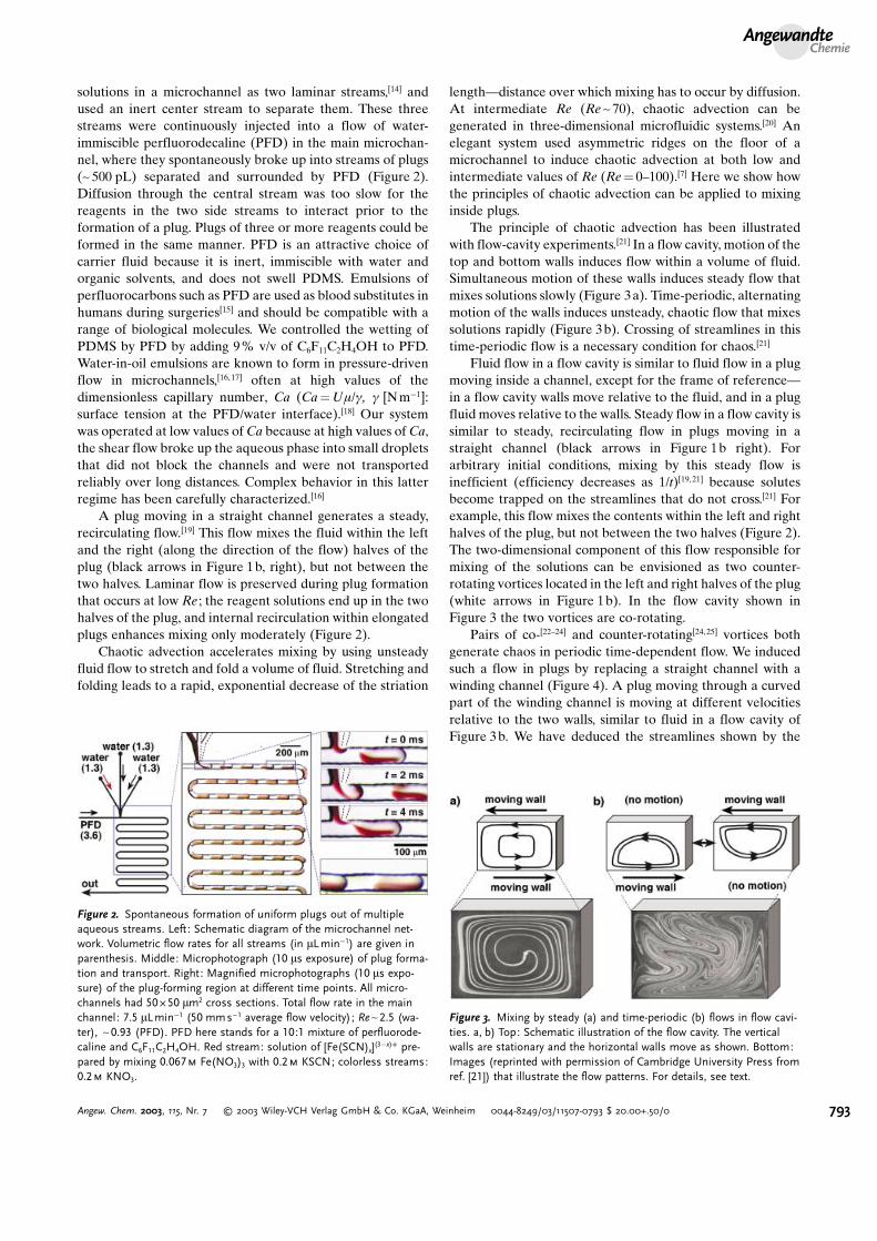
solutions in a microchannel as two laminar streams,[14] andused an inert center stream to separate them. These threestreams were continuously injected into a flow of water-immiscible perfluorodecaline (PFD) in the main microchan-nel, where they spontaneously broke up into streams of plugs(~ 500 pL) separated and surrounded by PFD (Figure 2).Diffusion through the central stream was too slow for thereagents in the two side streams to interact prior to theformation of a plug. Plugs of three or more reagents could beformed in the same manner. PFD is an attractive choice ofcarrier fluid because it is inert, immiscible with water andorganic solvents, and does not swell PDMS. Emulsions ofperfluorocarbons such as PFD are used as blood substitutes inhumans during surgeries[15] and should be compatible with arange of biological molecules. We controlled the wetting ofPDMS by PFD by adding 9% v/v of C6F11C2H4OH to PFD.Water-in-oil emulsions are known to form in pressure-drivenflow in microchannels,[16,17] often at high values of thedimensionless capillary number, Ca (Ca=Um/g, g [Nm�1]:surface tension at the PFD/water interface).[18] Our systemwas operated at low values ofCa because at high values ofCa,the shear flow broke up the aqueous phase into small dropletsthat did not block the channels and were not transportedreliably over long distances. Complex behavior in this latterregime has been carefully characterized.[16]
A plug moving in a straight channel generates a steady,recirculating flow.[19] This flow mixes the fluid within the leftand the right (along the direction of the flow) halves of theplug (black arrows in Figure 1b, right), but not between thetwo halves. Laminar flow is preserved during plug formationthat occurs at low Re ; the reagent solutions end up in the twohalves of the plug, and internal recirculation within elongatedplugs enhances mixing only moderately (Figure 2).
Chaotic advection accelerates mixing by using unsteadyfluid flow to stretch and fold a volume of fluid. Stretching andfolding leads to a rapid, exponential decrease of the striation
length—distance over which mixing has to occur by diffusion.At intermediate Re (Re~ 70), chaotic advection can begenerated in three-dimensional microfluidic systems.[20] Anelegant system used asymmetric ridges on the floor of amicrochannel to induce chaotic advection at both low andintermediate values of Re (Re= 0–100).[7] Here we show howthe principles of chaotic advection can be applied to mixinginside plugs.
The principle of chaotic advection has been illustratedwith flow-cavity experiments.[21] In a flow cavity, motion of thetop and bottom walls induces flow within a volume of fluid.Simultaneous motion of these walls induces steady flow thatmixes solutions slowly (Figure 3a). Time-periodic, alternatingmotion of the walls induces unsteady, chaotic flow that mixessolutions rapidly (Figure 3b). Crossing of streamlines in thistime-periodic flow is a necessary condition for chaos.[21]
Fluid flow in a flow cavity is similar to fluid flow in a plugmoving inside a channel, except for the frame of reference—in a flow cavity walls move relative to the fluid, and in a plugfluid moves relative to the walls. Steady flow in a flow cavity issimilar to steady, recirculating flow in plugs moving in astraight channel (black arrows in Figure 1b right). Forarbitrary initial conditions, mixing by this steady flow isinefficient (efficiency decreases as 1/t)[19,21] because solutesbecome trapped on the streamlines that do not cross.[21] Forexample, this flow mixes the contents within the left and righthalves of the plug, but not between the two halves (Figure 2).The two-dimensional component of this flow responsible formixing of the solutions can be envisioned as two counter-rotating vortices located in the left and right halves of the plug(white arrows in Figure 1b). In the flow cavity shown inFigure 3 the two vortices are co-rotating.
Pairs of co-[22–24] and counter-rotating[24,25] vortices bothgenerate chaos in periodic time-dependent flow. We inducedsuch a flow in plugs by replacing a straight channel with awinding channel (Figure 4). A plug moving through a curvedpart of the winding channel is moving at different velocitiesrelative to the two walls, similar to fluid in a flow cavity ofFigure 3b. We have deduced the streamlines shown by the
Figure 2. Spontaneous formation of uniform plugs out of multipleaqueous streams. Left: Schematic diagram of the microchannel net-work. Volumetric flow rates for all streams (in mLmin�1) are given inparenthesis. Middle: Microphotograph (10 ms exposure) of plug forma-tion and transport. Right: Magnified microphotographs (10 ms expo-sure) of the plug-forming region at different time points. All micro-channels had 50B50 mm2 cross sections. Total flow rate in the mainchannel: 7.5 mLmin�1 (50 mms�1 average flow velocity); Re~2.5 (wa-ter), ~0.93 (PFD). PFD here stands for a 10:1 mixture of perfluorode-caline and C6F11C2H4OH. Red stream: solution of [Fe(SCN)x](3�x)+ pre-pared by mixing 0.067m Fe(NO3)3 with 0.2m KSCN; colorless streams:0.2m KNO3.
Figure 3. Mixing by steady (a) and time-periodic (b) flows in flow cavi-ties. a, b) Top: Schematic illustration of the flow cavity. The verticalwalls are stationary and the horizontal walls move as shown. Bottom:Images (reprinted with permission of Cambridge University Press fromref. [21]) that illustrate the flow patterns. For details, see text.
AngewandteChemie
793Angew. Chem. 2003, 115, Nr. 7 � 2003 Wiley-VCH Verlag GmbH & Co. KGaA, Weinheim 0044-8249/03/11507-0793 $ 20.00+.50/0
white arrows in Figure 1b by observing asymmetric plugstraveling through curved channels; these streamlines aresimilar to those shown in Figure 3b. In plugs moving through
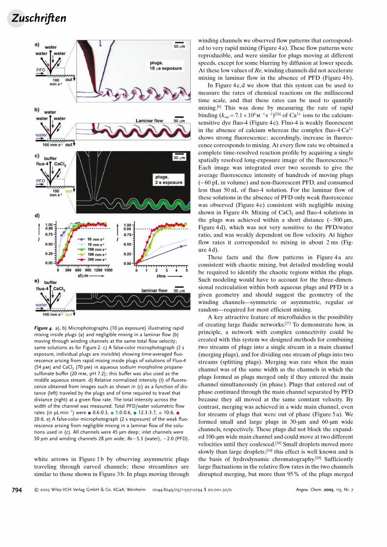
winding channels we observed flow patterns that correspond-ed to very rapid mixing (Figure 4a). These flow patterns werereproducible, and were similar for plugs moving at differentspeeds, except for some blurring by diffusion at lower speeds.At these low values ofRe, winding channels did not acceleratemixing in laminar flow in the absence of PFD (Figure 4b).
In Figure 4c,d we show that this system can be used tomeasure the rates of chemical reactions on the millisecondtime scale, and that these rates can be used to quantifymixing.[6] This was done by measuring the rate of rapidbinding (kon= 7.1 C 108
m�1 s�1)[26] of Ca2+ ions to the calcium-
sensitive dye fluo-4 (Figure 4c). Fluo-4 is weakly fluorescentin the absence of calcium whereas the complex fluo-4·Ca2+
shows strong fluorescence; accordingly, increase in fluores-cence corresponds to mixing. At every flow rate we obtained acomplete time-resolved reaction profile by acquiring a singlespatially resolved long-exposure image of the fluorescence.[8]
Each image was integrated over two seconds to give theaverage fluorescence intensity of hundreds of moving plugs(~ 60 pL in volume) and non-fluorescent PFD, and consumedless than 50 nL of fluo-4 solution. For the laminar flow ofthese solutions in the absence of PFD only weak fluorescencewas observed (Figure 4e) consistent with negligible mixingshown in Figure 4b. Mixing of CaCl2 and fluo-4 solutions inthe plugs was achieved within a short distance (~ 500 mm,Figure 4d), which was not very sensitive to the PFD/waterratio, and was weakly dependent on flow velocity. At higherflow rates it corresponded to mixing in about 2 ms (Fig-ure 4d).
These facts and the flow patterns in Figure 4a areconsistent with chaotic mixing, but detailed modeling wouldbe required to identify the chaotic regions within the plugs.Such modeling would have to account for the three-dimen-sional recirculation within both aqueous plugs and PFD in agiven geometry and should suggest the geometry of thewinding channels—symmetric or asymmetric, regular orrandom—required for most efficient mixing.
A key attractive feature of microfluidics is the possibilityof creating large fluidic networks.[27] To demonstrate how, inprinciple, a network with complex connectivity could becreated with this system we designed methods for combiningtwo streams of plugs into a single stream in a main channel(merging plugs), and for dividing one stream of plugs into twostreams (splitting plugs). Merging was rare when the mainchannel was of the same width as the channels in which theplugs formed as plugs merged only if they entered the mainchannel simultaneously (in phase). Plugs that entered out ofphase continued through the main channel separated by PFDbecause they all moved at the same constant velocity. Bycontrast, merging was achieved in a wide main channel, evenfor streams of plugs that were out of phase (Figure 5a). Weformed small and large plugs in 30-mm and 60-mm widechannels, respectively. These plugs did not block the expand-ed 100-mm wide main channel and could move at two differentvelocities until they coalesced.[28] Small droplets moved moreslowly than large droplets;[16] this effect is well known and isthe basis of hydrodynamic chromatography.[29] Sufficientlylarge fluctuations in the relative flow rates in the two channelsdisrupted merging, but more than 95% of the plugs merged
Figure 4. a), b) Microphotographs (10 ms exposure) illustrating rapidmixing inside plugs (a) and negligible mixing in a laminar flow (b)moving through winding channels at the same total flow velocity;same solutions as for Figure 2. c) A false-color microphotograph (2 sexposure, individual plugs are invisible) showing time-averaged fluo-rescence arising from rapid mixing inside plugs of solutions of Fluo-4(54 mm) and CaCl2 (70 mm) in aqueous sodium morpholine propane-sulfonate buffer (20 mm, pH 7.2); this buffer was also used as themiddle aqueous stream. d) Relative normalized intensity (I) of fluores-cence obtained from images such as shown in (c) as a function of dis-tance (left) traveled by the plugs and of time required to travel thatdistance (right) at a given flow rate. The total intensity across thewidth of the channel was measured. Total PFD/water volumetric flowrates (in mLmin�1) were * 0.6:0.3, * 1.0:0.6, * 12.3:3.7, * 10:6, *20:6. e) A false-color microphotograph (2 s exposure) of the weak fluo-rescence arising from negligible mixing in a laminar flow of the solu-tions used in (c). All channels were 45 mm deep; inlet channels were50 mm and winding channels 28 mm wide; Re~5.3 (water), ~2.0 (PFD).
Zuschriften
794 � 2003 Wiley-VCH Verlag GmbH & Co. KGaA, Weinheim 0044-8249/03/11507-0794 $ 20.00+.50/0 Angew. Chem. 2003, 115, Nr. 7
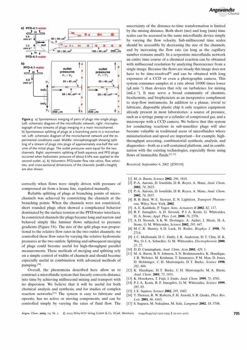
correctly when flows were simply driven with pressure ofcompressed air from a house line, regulated manually.
Reliable splitting of plugs at branching points of micro-channels was achieved by constricting the channels at thebranching points. When the channels were not constricted,short rounded plugs often showed a complicated behaviordominated by the surface tension at the PFD/water interfaces.In constricted channels the plugs became long and narrow andbehaved simply like laminar flows subjected to pressuregradients (Figure 5b). The size of the split plugs was propor-tional to the relative flow rates in the two outlet channels; wecontrolled these flow rates by varying the relative hydrostaticpressures at the two outlets. Splitting and subsequent mergingof plugs could become useful for high-throughput parallelmeasurements. These methods of merging and splitting relyon a simple control of widths of channels and should becomeespecially useful in combination with advanced methods ofpumping.[30]
Overall, the phenomena described here allow us toconstruct a microfluidic system that linearly converts distanceinto time by achieving millisecond mixing and transport withno dispersion. We believe that it will be useful for bothchemical analysis and synthesis, and for studies of complexreaction networks.[31] The system is easy to fabricate andoperate, has no active or moving components, and can becontrolled simply by varying the rates of fluid flow. The
uncertainty of the distance-to-time transformation is limitedby the mixing distance. Both short (ms) and long (min) timescales can be accessed in the same microfluidic device simplyby varying the flow velocity. Sub-millisecond time scalesshould be accessible by decreasing the size of the channels,and by increasing the flow rate (as long as the capillarynumber remains small). In a serpentine microfluidic networkan entire time course of a chemical reaction can be obtainedwith millisecond resolution by analyzing fluorescence from asingle image. Because the flows are steady this image does nothave to be time-resolved[8] and can be obtained with longexposures of a CCD or even a photographic camera. Thissystem consumes samples at a rate about 10000 times lower(mLmin�1) than devices that rely on turbulence for mixing(mLs�1). It may serve a broad community of chemists,biochemists, and biophysicists as an inexpensive complimentto stop-flow instruments. In addition to a planar, trivial tofabricate, disposable plastic chip it only requires equipmentalready present in most laboratories: a source of pressure,such as a syringe pump or a cylinder of compressed gas, and amicroscope with a CCD camera. We believe that this systemfor conducting reactions in sub-nanoliter plugs will alsobecome valuable in traditional areas of microfluidics whereminiaturization and speed are important—for example, high-throughput screening, combinatorial synthesis, analysis, anddiagnostics—both as a self-contained platform, and in combi-nation with the existing technologies, especially those usingflows of immiscible fluids.[32,33]
Received: September 6, 2002 [Z50110]
[1] M. A. Burns, Science 2002, 296, 1818.[2] P.-A. Auroux, D. Iossifidis, D. R. Reyes, A. Manz, Anal. Chem.
2002, 74, 2623.[3] P.-A. Auroux, D. Iossifidis, D. R. Reyes, A. Manz, Anal. Chem.
2002, 74, 2637.[4] R. B. Bird, W. E. Stewart, E. N. Lightfoot, Transport Phenom-
ena, Wiley, New York, 2002.[5] A. E. Kamholz, P. Yager, Sens. Actuators B 2002, 82, 117.[6] R. F. Ismagilov, A. D. Stroock, P. J. A. Kenis, G. Whitesides,
H. A. Stone, Appl. Phys. Lett. 2000, 76, 2376.[7] A. D. Stroock, S. K. W. Dertinger, A. Ajdari, I. Mezic, H. A.
Stone, G. M. Whitesides, Science 2002, 295, 647.[8] M. C. R. Shastry, S. D. Luck, H. Roder, Biophys. J. 1998, 74,
2714.[9] J. C. McDonald, D. C. Duffy, J. R. Anderson, D. T. Chiu, H. K.
Wu, O. J. A. Schueller, G. M. Whitesides, Electrophoresis 2000,21, 27.
[10] D. D. Cunningham, Anal. Chim. Acta 2001, 429, 1.[11] M. A. Burns, B. N. Johnson, S. N. Brahmasandra, K. Handique,
J. R. Webster, M. Krishnan, T. Sammarco, P. M. Man, D. Jones,D. Heldsinger, C. H. Mastrangelo, D. T. Burke, Science 1998,282, 484.
[12] K. Handique, D. T. Burke, C. H. Mastrangelo, M. A. Burns,Anal. Chem. 2001, 73, 1831.
[13] K. Hosokawa, T. Fujii, I. Endo, Anal. Chem. 1999, 71, 4781.[14] P. J. A. Kenis, R. F. Ismagilov, G. M. Whitesides, Science 1999,
285, 83.[15] J. E. Squires, Science 2002, 295, 1002.[16] T. Thorsen, R. W. Roberts, F. H. Arnold, S. R. Quake, Phys. Rev.
Lett. 2001, 86, 4163.[17] S. Sugiura, M. Nakajima, M. Seki, Langmuir 2002, 18, 5708.
Figure 5. a) Spontaneous merging of pairs of plugs into single plugs.Left: schematic diagram of the microfluidic network; right: micropho-tograph of two streams of plugs merging in a main microchannel.b) Spontaneous splitting of plugs at a branching point in a microchan-nel. Left: schematic diagram of the microchannel network and the ex-perimental conditions used. Middle: microphotograph showing split-ting of a stream of plugs into plugs of approximately one-half the vol-ume of the initial plugs. The outlet pressures were equal for the twochannels. Right: asymmetric splitting of both aqueous and PFD plugsoccurred when hydrostatic pressure of about 6 kPa was applied to thesecond outlet. a), b) Volumetric PFD/water flow rate ratios, flow veloci-ties, and cross-sectional dimensions of the channels (widthBheight)are also shown.
AngewandteChemie
795Angew. Chem. 2003, 115, Nr. 7 � 2003 Wiley-VCH Verlag GmbH & Co. KGaA, Weinheim 0044-8249/03/11507-0795 $ 20.00+.50/0
[18] The viscosity of PFD is 5.10 C 10�3 kgm�3 s�1, the surface tensionat the interface between water and fluorinated phase was13C 10�3 Nm�1. We have shown that this system can be operatedat values of Ca up to about 0.1 (at 300 mms�1). As the value ofCa increases above about 0.2, the formation of plugs becomesirregular.
[19] K. Handique, M. A. Burns, J. Micromech. Microeng. 2001, 11,548.
[20] R. H. Liu, M. A. Stremler, K. V. Sharp, M. G. Olsen, J. G.Santiago, R. J. Adrian, H. Aref, D. J. Beebe, J. Microelectromech.Syst. 2000, 9, 190.
[21] J. M. Ottino, The Kinematics of Mixing: Stretching, Chaos, andTransport, Cambridge University Press, Cambridge, 1989.
[22] H. Aref, J. Fluid Mech. 1984, 143, 1.[23] W. L. Chien, H. Rising, J. M. Ottino, J. Fluid Mech. 1986, 170,
355.[24] S. C. Jana, G. Metcalfe, J. M. Ottino, J. Fluid Mech. 1994, 269,
199.[25] T. H. Solomon, J. P. Gollub, Phys. Rev. A 1988, 38, 6280.[26] M. Naraghi, Cell Calcium 1997, 22, 255.[27] T. Thorsen, S. J. Maerkl, S. R. Quake, Science 2002, 298, 580.[28] J. Eggers, J. R. Lister, H. A. Stone, J. Fluid Mech. 1999, 401, 293.[29] H. Small, M. A. Langhorst, Anal. Chem. 1982, 54, A892.[30] M. A. Unger, H. P. Chou, T. Thorsen, A. Scherer, S. R. Quake,
Science 2000, 288, 113.[31] A. Arkin, P. D. Shen, J. Ross, Science 1997, 277, 1275.[32] B. Zhao, N. O. L. Viernes, J. S. Moore, D. J. Beebe, J. Am. Chem.
Soc. 2002, 124, 5284.[33] M. Tokeshi, T. Minagawa, K. Uchiyama, A. Hibara, K. Sato, H.
Hisamoto, T. Kitamori, Anal. Chem. 2002, 74, 1565.
Zuschriften
796 � 2003 Wiley-VCH Verlag GmbH & Co. KGaA, Weinheim 0044-8249/03/11507-0796 $ 20.00+.50/0 Angew. Chem. 2003, 115, Nr. 7