Embed Size (px)
Citation preview
260 Philips Tech. Rev. 43, No. 9, 260-268, Sept.1987
A mobile system for image bulk storage
L. H. Guildford and B. D. Young
There are many kinds of video signals besides those from television. Many other kinds of sys-tems produce images from sensors; they range from infrared surveillance systems to Xsraydiagnostic equipment. Sometimes it is essential to be able to record signals for later analysisoff-site. This requires far more elaborate equipment for image bulk storage than an ordinaryvideo recorder. Recently at Philips Research Laboratories hardware and software have beendeveloped to cope with the many possible eventualities. The instrumentation is in fact a com-plex system that constitutes a complete transportable laboratory.
Introduction
Television cameras, night-viewing systems, infraredsurveillance systems, ultrasound systems, radar, sonar,X-ray diagnostic equipment - these all produce im-ages from sensor systems. The images have to be pro-cessed for simple display, to activate further systemsor perhaps to provide a better understanding of theobservations or of the operation of the actual system.
Experiments in real-time image processing withsuch systems are often desirable, but there are prob-lems. The actual scene itself may be unique and eco-nomically unrepeatable, taking place in difficult en-vironmental conditions. The image might for examplebe due to a low-flying aircraft detected and trackedby infrared sensors in unusual weather conditions. Itcould come from an X-ray medical investigation,where the patient's discomfort should be kept as briefas possible.It is therefore highly desirable to record the video
information from the sensors on the spot. Then theimages can be recreated, studied and processed at willlater. The recording must be such that high-qualityunadulterated video information from the sensorsystem is readily available.Ultimately there are various options: the inforrna-
tion may be viewed directly as a two-dimensional pic-ture, plotted as a graph or perhaps used as the basicdata for the recognition of a characteristic pattern (an'object signature') to trigger automatic reaction by asystem.
L. H. Guildford, M.l.E.R.E., was formerly with Philips ResearchLaboratories, RedhilI, Surrey, England; B. D. Young, B.Sc.,A.M.l.E.E., is with these laboratories.
Collecting and recording the video signals fromdifferent types of sensor systems requires a sophisti-cated image bulk store with the appropriate equip-ment for preprocessing and postprocessing. Such astorage system including all the ancillary hardwareforms the subject of this article. The system is designedfor monochrome ('black and white') images only.
Image signal characteristics
Some of the sensor systems listed above will presentinformation as a signal that is compatible with the in-ternational CCIR standards for television [11. Othersmake use of more unusual scene-scanning formats. Ingeneral these will be line-scanning structures based onrectilinear formats (as in television, but with differentparameter values), radial line scans (as in radar) orverticalline scans swept horizontally to produce a 3600'cylindrical' scan for omnidirectional surveillance.The signals from the sensors will often be in analog
form, sometimes with synchronization pulses inter-leaved with the video signals proper, thus producingcomposite waveforms. Sometimes, however, videoand synchronization signals are provided on separateconnections. Digitized signals supplied directly fromthe sensors will become more common in future. Thismeans that our system for image bulk storage must becapable of dealing with both analog and digital signalformats and with a wide variety of scan-synchroniza-tion signals.However the signals from the sensors are to be dis-
played or used, certain operational parameters always
Philips Tech. Rev. 43, No. 9 IMAGE-STORAGE SYSTEM 261
I~-~-~
syncencoder
analogpre-
processor
digilalvideo
--~-_.~~-~-,
syncdecoder
analogpost-
to monitor
computer-compatible
laperecorder
to externaldigital signal
processor
I
I
L . . ~_~J
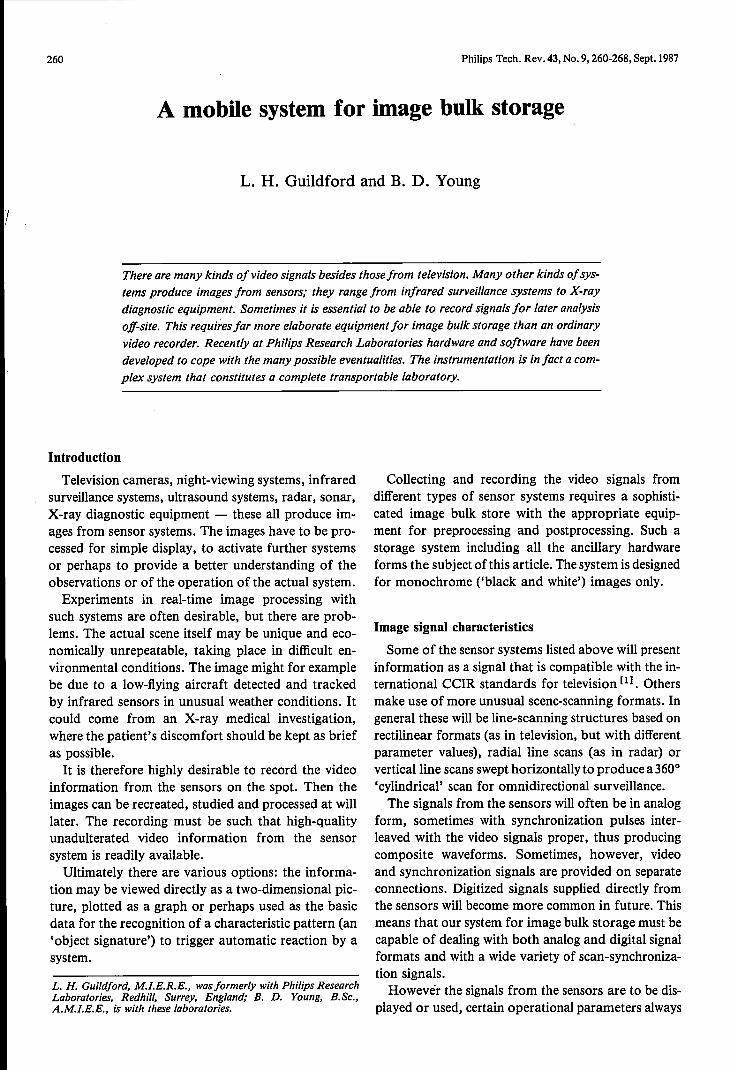
Fig. I.Basic functional diagram of the mobile system for image bulk storage. The system consistsof a number of subsystems that can be interconnected in a variety of ways to suit the particularneeds of the user. All signal processing is basically digital. Analog video signals are therefore firstconverted to digital and back to analog after processing. The actual image bulk store is a 24-tracktape recorder. An electronic frame store and a computer-compatible tape recorder are also avail-able. For synchronization purposes special encoder and decoder circuits have been designed. Theentire system is controlled from the system-control computer.
have to be established and maintained for recordingand analysing the information.• A zero reference level for the video signal (the'black level'). This can be either absolute or related tothe scene.• The dynamic range for the signal from the sensors.This is normally expressed as the range between theblack level, as a reference value, and the peak levelrepresenting white.• The resolution of the signal. Two kinds of resolu-tion are significant: the spatial resolution in terms ofthe number of picture elements (pixels) or sampleswithin a given image region, and the amplitude reso-lution in terms of signal-to-noise ratio, minimum de-tectable signalor number of bits per sample.• The system characteristics of the overall systemfrom the output of the sensors to the point of meas-urement. They should be linear and the correspondingfrequency response should be as flat as possible.For infrared systems the dynamic range of the
video signal can be greater than 60 dB (an amplituderatio of 1000: 1, requiring at least 10 bits per sample),but mostly a dynamic range of 48 dB (an amplituderatio of 250: 1, requiring at least 8 bits per sample) issufficient.For monochrome television signals a sampling rate
of about 12 MHz is necessary. In processing the sig-nals of other image-sensing applications of interestsampling rates as high as 18 MHz can occur, especial-ly when two or more signals are combined in time-
system-conlrolcompuier
division multiplex to allow a number of different sen-sor devices to view the same scene simultaneously.
All the normal scan formats produce some degreeof 'dead time' in which no video information is pro-duced. For instance, the scanning formats used withstandard television systems allow approximately 200/0of the time for scan flyback. Infrared scanners withoptomechanical scanning often produce as much as50% of dead time. By storing and reformatting the in-coming information, the effective bandwidth requiredof a recording medium can be reduced. It is also pos-sible to reduce the amount of storage required perframe, if the information relating to the dead times iskept to the absolute minimum.
System requirements
From the outset we wanted our system for imagebulk storage to meet the following basic require-ments.• It must make a high-quality record of incomingimages.• Itmust enable the replay of recorded information atthe original recording speed and at various much lowerspeeds.
[IJ Report No. 308-2, Characteristics of monochrome televisionsystems, Proc. XIIth CCIR Plenary Assembly, Vol. V, pt. 2,New Delhi 1970 (published by the ITU, Geneva 1970);Report No. 624-2, Characteristics of television systems,Recommendations and reports of the CCIR, Vol. XI, pt. 1,Broadcasting service (television), ITU, Geneva 1982.
262 L. H. GUILDFORD and B. D. YOUNG Philips Tech. Rev. 43, No. 9
pre-processor
analogvideo
system-control bus
\4--------~ system-controlcomputer
originalvideo
replayedvideo
post-processor
computer-compatible
taperecorder
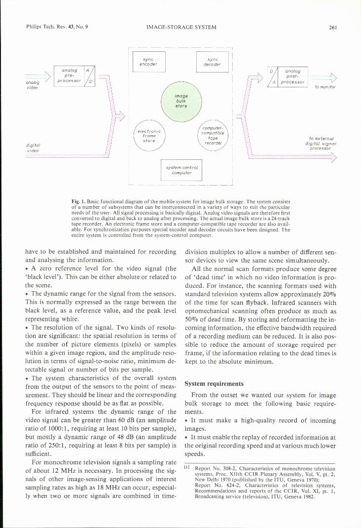
Fig.2. System configuration for storing standard analog television signals. After analog prepro-cessing and AID conversion the sync encoder replaces the conventional sync information by digi-tal information for both synchronization and image-identification purposes. The signal is thenstored in the image bulk store. On replay individual frames are stored in the frame store. They canbe transferred to the computer-compatible tape recorder for further off-line processing or theycan be viewed on a monitor after DIA conversion and appropriate postprocessing. Connectionsintended for synchronization purposes are indicated by dashed lines. The system is controlledfrom a computer terminal via the system-control computer and the system-control bus .
• It must be possible to obtain still pictures ('frozenframes'), so that information can be examined frameby frame.• It must include a computer-compatible tape record-er (with 1/2-inch tape) for recording a selected stillpicture. Recorded images can then be analysed off-line by an external computer, manipulated as requiredwithin that computer and replayed at will for furtheruse.• The hardware of the complete system must be self-contained and transportable.Now that the image signal characteristics, described
in the previous section, are known the basic function-al diagram of jig. I can be derived; it shows the indivi-dual modules required. Because the main functionsare executed digitally any analog video input signal isfirst preprocessed and converted to digital. Similarlyany analog video output signal is obtained from thesystem after digital-to-analog conversion and post-processing. The heart of the system consists of threestorage media:• an electronic store that can contain two televisionframes at a time,• an image tape recorder, which constitutes the actualimage bulk store, and
• a computer-compatible tape recorder that serves asan output device enabling external processing later,e.g. on a mainframe computer.
As we are dealing with video signals, synchroniza-tion is an important aspect of the interaction of inputdevices, output devices and storage media. Two separ-ate units indicated by 'sync encoder' and 'sync deco-der' are provided for this purpose.
The system-control computer is used to set up andmonitor all operations.
System architecture
The modules of fig. 1are deliberately shown withoutinterconnections; depending on the particular appli-cation of the system the modules may be connected inmany different ways. For instance, the frame storemay be placed either before or after the bulk storeor not used at all. There are many possible config-urations to suit the user's needs, both for recording andreplaying television or non-standard image formats.All modules have therefore been made plug-com-patible at their interfaces so that they can easily bepatched together to produce a great variety of record-ing and replay functions.
Philips Tech. Rev. 43, No. 9 IMAGE-STORAGE SYSTEM 263
One specific system configuration with its intercon-nections is shown in fig. 2. This configuration can beused for processing a standard analog television signal.After preprocessing, AID conversion and sync encod-ing the signal is recorded digitally in the bulk store.On replaying the video recording the signal passesthrough the sync decoder, is reformatted in the framestore and after subsequent DIA conversion and post-processing is replayed on a television monitor. Alter-natively individual frames may be selected for detailedexamination on the monitor or recorded on the com-puter-compatible tape recorder.
Some particular features of this configuration are:• the monitor can display either the original or the re-played video signal;
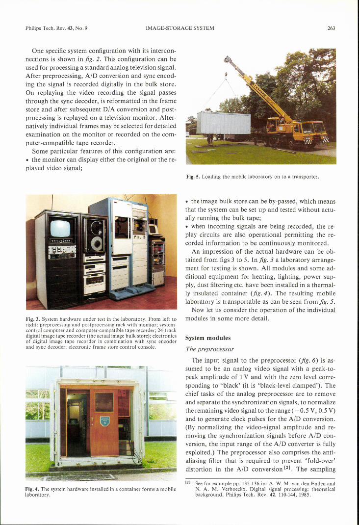
Fig. 5. Loading the mobile laboratory on to a transporter.
• the image bulk store can be by-passed, which meansthat the system can be set up and tested without actu-ally running the bulk tape;• when incoming signals are being recorded, the re-play circuits are also operational permitting the re-corded information to be continuously monitored.
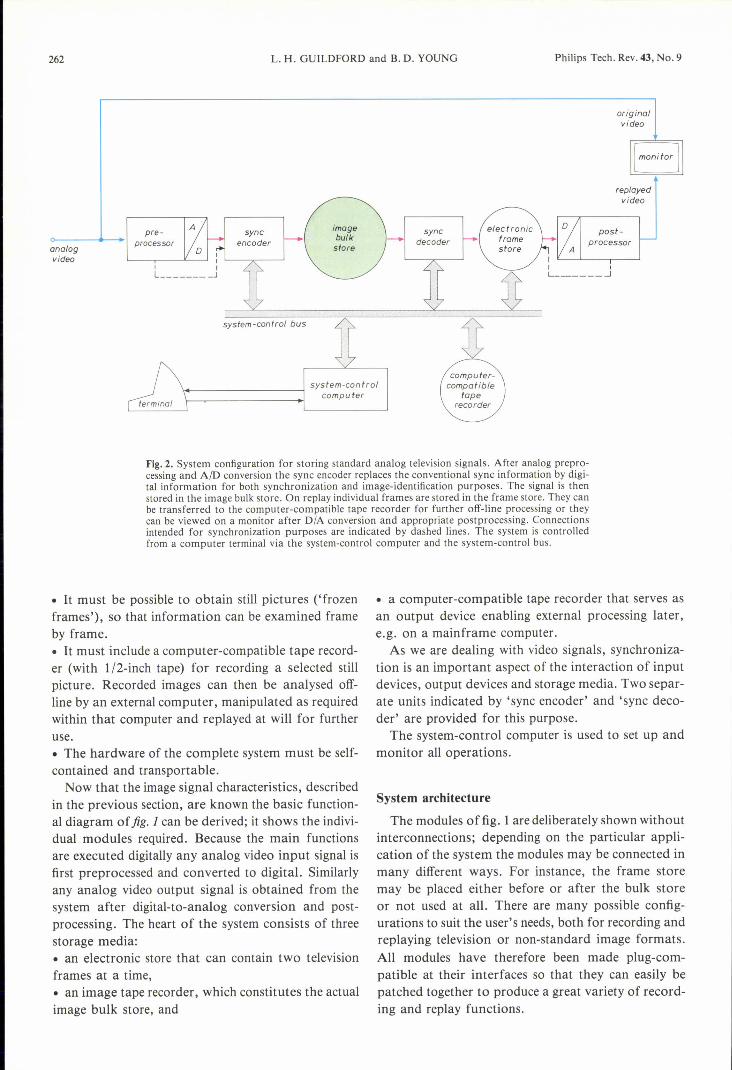
An impression of the actual hardware can be ob-tained from figs 3 to 5. In fig. 3 a laboratory arrange-ment for testing is shown. All modules and some ad-ditional equipment for heating, lighting, power sup-ply, dust filtering etc. have been installed in a thermal-ly insulated container (fig.4). The resulting mobilelaboratory is transportable as can be seen fromfig. 5.
Now let us consider the operation of the individualFig.3. System hardware under test in the laboratory. From left to modules in some more detail.right: preprocessing and postprocessing rack with monitor; system-control computer and computer-compatible tape recorder; 24-trackdigital image tape recorder (the actual image bulk store); electronics System modulesof digital image tape recorder in combination with sync encoderand sync decoder; electronic frame store control console. The preprocessor
[21 See for example pp. 135-136 in: A. W. M. van den Enden andFig. 4. The system hardware installed in a container forms a mobile N. A. M. Verhoeckx, Digital signal processing: theoreticallaboratory. background, Philips Tech. Rev. 42, 110-144,1985.
The input signal to the preprocessor (fig. 6) is as-sumed to be an analog video signal with a peak-to-peak amplitude of 1V and with the zero level corre-sponding to 'black' (it is 'black-level clamped'). Thechief tasks of the analog preprocessor are to removeand separate the synchronization signals, to normalizethe remaining video signal to the range ( - 0.5 V, 0.5 V)and to generate clock pulses for the AID conversion.(By normalizing the video-signal amplitude and re-moving the synchronization signals before AID con-version, the input range of the AID converter is fullyexploited.) The preprocessor also comprises the anti-aliasing filter that is required to prevent 'fold-over'distortion in the AID conversion [21. The sampling
264 L. H. GUILDFORD and B. D. YOUNG Philips Tech. Rev. 43, No. 9
1----------1
i ~::] M r=.[ZJ ,~;~i> (;;;~:L,-----+ FILTER I ~/OCk
i D ~~-J1A I1v I ,--------, I~ lSbits
SYNCo>-----t·1analog v ideo
I
I
I
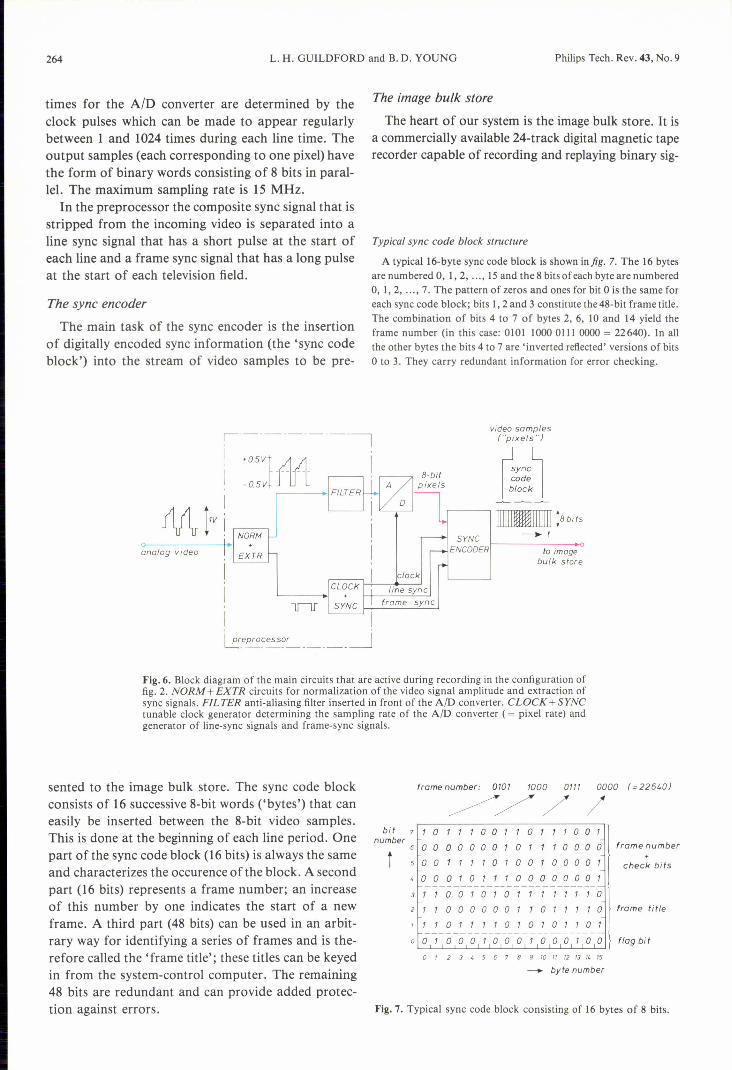
times for the AID converter are determined by theclock pulses which can be made to appear regularlybetween 1 and 1024 times during each line time. Theoutput samples (each corresponding to one pixel) havethe form of binary words consisting of 8 bits in paral-lel. The maximum sampling rate is 15 MHz.
In the preprocessor the composite sync signal that isstripped from the incoming video is separated into aline sync signal that has a short pulse at the start ofeach line and a frame sync signal that has a long pulseat the start of each television field.
The sync encoder
The main task of the sync encoder is the insertionof digitally encoded sync information (the 'sync codeblock') into the stream of video samples to be pre-
The image bulk store
The heart of our system is the image bulk store. It isa commercially available 24-track digital magnetic taperecorder capable of recording and replaying binary sig-
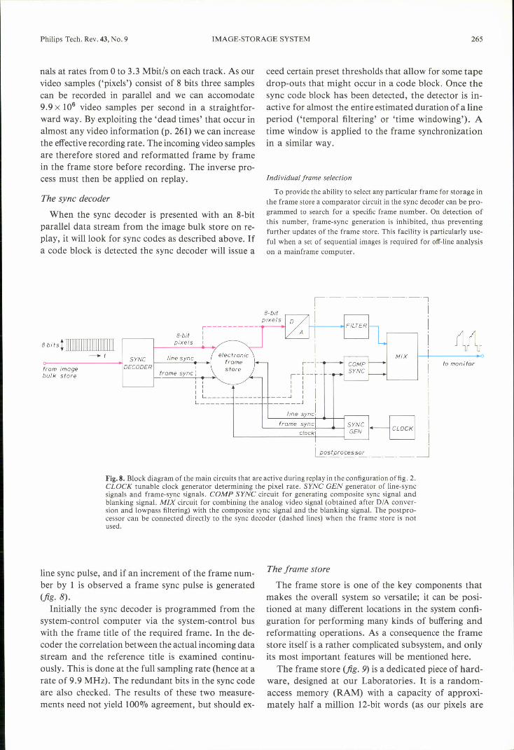
Typical sync code block structure
A typical Iê-byte sync code block is shown in fig. 7. The 16 bytesare numbered 0, I, 2, ... , IS and the 8 bits of each byte are numbered0, I, 2, ... , 7. The pattern of zeros and ones for bit 0 is the same foreach sync code block; bits 1,2 and 3 constitute the 48-bit frame title.The combination of bits 4 to 7 of bytes 2, 6, ID and 14 yield theframe number (in this case: 0101 1000 Dill 0000 = 22640). In allthe other bytes the bits 4 to 7 are 'inverted reflected' versions of bitso to 3. They carry redundant information for error checking.
video samplest=oixets")
lock
f------- ....oto image
bulk store
I nreprocessor _jL:---~-------
Fig.6. Block diagram of the main circuits that are active during recording in the configuration offig. 2. NORM +EXTR circuits for normalization of the video signal amplitude and extraction ofsync signals. FlL TER anti-aliasing filter inserted in front of the AID converter. CLOCK + SYNCtunable clock generator determining the sampling rate of the AID converter (= pixel rate) andgenerator of line-sync signals and frame-sync signals.
sented to the image bulk store. The sync code blockconsists of 16 successive 8-bit words ('bytes') that caneasily be inserted between the 8-bit video samples.This is done at the beginning of each line period. Onepart of the sync code block (16 bits) is always the sameand characterizes the occurence of the block. A secondpart (16 bits) represents a frame number; an increaseof this number by one indicates the start of a newframe. A third part (48 bits) can be used in an arbit-rary way for identifying a series of frames and is the-refore called the' frame title'; these titles can be keyedin from the system-control computer. The remaining48 bits are redundant and can provide added protee-tion against errors.
framenumber: 0101 1000 0111 0000 (=22640)
~///bi t 7 1 0 1 1 1 0 0 1 1 0 1 1 7 0 0 1
number 6 0 0 0 0 0 0 0 1 0 1 7 1 0 0 0 0 frame number
t 5 0 0 1 1 7 1 0 1 0 0 1 0 0 0 0 1 check bits
40001071100000001--------------------------
31100101011111110
2 1 1 0 0 0 0 0 0 1 1 0 1 1 1 1 0 frame ti tie
11/01111010101101
o 0 1 0 0 0 1 0 0 0 1 0 0 0 1 0 0 flag bit
o 1 2 3 I. 5 6 7 8 9 10 11 12 13 71. 15
-. byte number
Fig. 7. Typical sync code block consisting of 16 bytes of 8 bits.
Philips Tech. Rev. 43, No. 9 IMAGE-STORAGE SYSTEM 265
nals at rates from 0 to 3.3 Mbit/s on each track. As ourvideo samples ('pixels') consist of 8 bits three samplescan be recorded in parallel and we can accomodate9.9 x 106 video samples per second in a straightfor-ward way. By exploiting the 'dead times' that occur inalmost any video information (p. 261) we can increasethe effectiverecording rate. The incoming video samplesare therefore stored and reformatted frame by framein the frame store before recording. The inverse pro-cess must then be applied on replay.
The sync decoder
When the sync decoder is presented with an 8-bitparallel data stream from the image bulk store on re-play, it will look for sync codes as described above. Ifa code block is detected the sync decoder will issue a
a-bitpixels
8 bitst 11111111111111111111111111
-t SYNC line syncDECODER I
frame sync:from imagebulk store
ceed certain preset thresholds that allow for some tapedrop-outs that might occur in a code block. Once thesync code block has been detected, the detector is in-active for almost the entire estimated duration of a lineperiod ('temporal filtering' or 'time windowing'). Atime window is applied to the frame synchronizationin a similar way.
Individual frame selection
To provide the ability to select any partienlar frame for storage inthe frame store a comparator circuit in the sync decoder can be pro-grammed to search for a specific frame number. On detection ofthis number, frame-sync generation is inhibited, thus preventingfurther updates of the frame store. This facility is particularly use-ful when a set of sequential images is required for off-line analysison a mainframe computer.
to monitor
frame sync
I .....ostprocessor~-------------
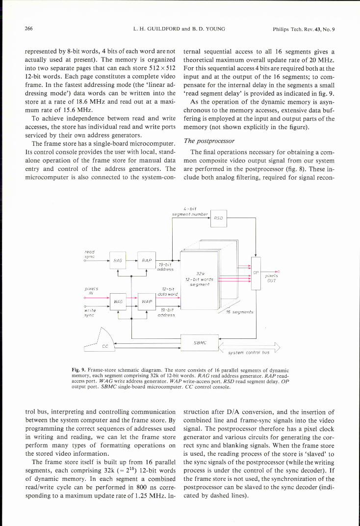
Fig. 8. Block diagram of the main circuits that are active during replay in the configuration offig. 2.CLOCK tunable clock generator determining the pixel rate. SYNC GEN generator of line-syncsignals and frame-sync signals. CaMP SYNC circuit for generating composite sync signal andblanking signal. MIX circuit for combining the analog video signal (obtained after DIA conver-sion and lowpass filtering) with the composite sync signal and the blanking signal. The postpro-cessor can be connected directly to the sync decoder (dashed lines) when the frame store is notused.
line sync pulse, and if an increment of the frame num-ber by 1 is observed a frame sync pulse is generated(jig. 8).
Initially the sync decoder is programmed from thesystem-control computer via the system-control buswith the frame title of the required frame. In the de-coder the correlation between the actual incoming datastream and the reference title is examined continu-ously. This is done at the full sampling rate (hence at arate of 9.9 MHz). The redundant bits in the sync codeare also checked. The results of these two measure-ments need not yield 100010agreement, but should ex-
The frame store
The frame store is one of the key components thatmakes the overall system so versatile; it can be posi-tioned at many different locations in the system confi-guration for performing many kinds of buffering andreformatting operations. As a consequence the framestore itself is a rather complicated subsystem, and onlyits most important features will be mentioned here.
The frame store (jig. 9) is a dedicated piece of hard-ware, designed at our Laboratories. It is a random-access memory (RAM) with a capacity of approxi-mately half a million 12-bit words (as our pixels are
266 L. H. GUILDFORD and B. D. YOUNG Philips Tech. Rev. 43, No. 9
represented by 8-bit words, 4 bits of each word are notactually used at present). The memory is organizedinto two separate pages that can each store 512 x 51212-bit words. Each page constitutes a complete videoframe. In the fastest addressing mode (the 'linear ad-dressing mode') data words can be written into thestore at a rate of 18.6 MHz and read out at a maxi-mum rate of 15.6 MHz.To achieve independenee between read and write
accesses, the store has individual read and write portsserviced by their own address generators.The frame store has a single-board microcomputer.
Its control console provides the user with local, stand-alone operation of the frame store for manual dataentry and control of the address generators. Themicrocomputer is also connected to the system-con-
readsync
12-bitdata word
19-bitaddress
pixelsIN
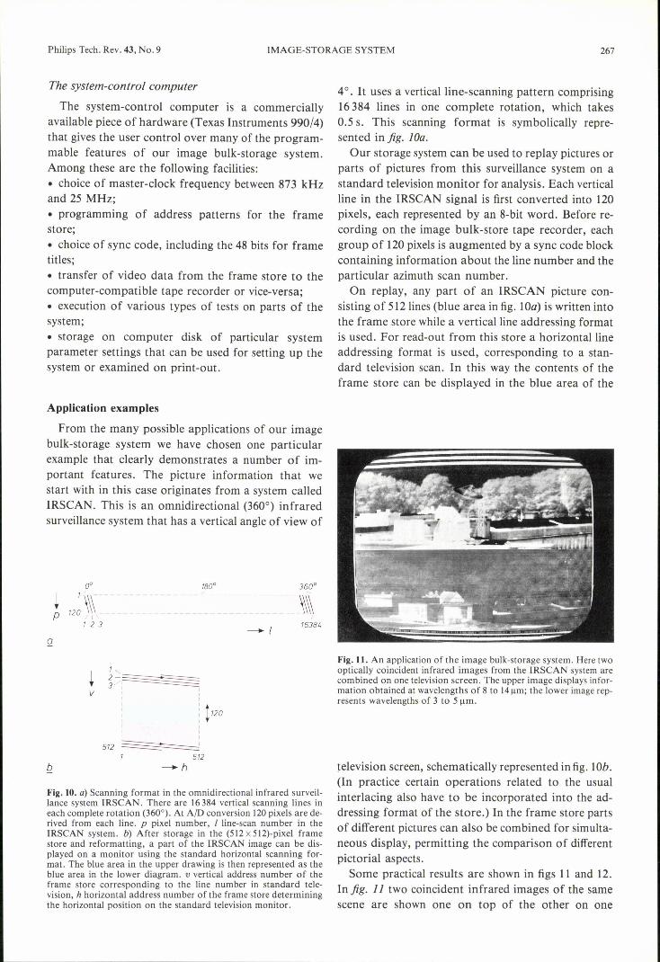
ternal sequential access to all 16 segments gives atheoretical maximum overall update rate of 20 MHz.For this sequential access 4 bits are required both at theinput and at the output of the 16 segments; to com-pensate for the internal delay in the segments a small'read segment delay' is provided as indicated in fig. 9.As the operation of the dynamic memory is asyn-
chronous to the memoryaccesses, extensive data buf-fering is employed at the input and output parts of thememory (not shown explicitly in the figure).
The postprocessor
The final operations necessary for obtaining a com-mon composite video output signal from our systemare performed in the postprocessor (fig. 8). These in-clude both analog filtering, required for signal recon-
4 -bi tsegment number
32k pixelsOUT12- bit words
segment
writesync
~1~9~-b~ift~----------111 ~%& segmentsaddress
ccsystem control bus
SBMe
Fig.9. Frame-store schematic diagram. The store consists of 16 parallel segments of dynamicmemory, each segment comprising 32k of 12-bitwords. RAG read address generator. RAP read-access port. WAG write address generator. WAP write-access port. RSD read segment delay. OPoutput port. SBMC single-board microcomputer. CC control console.
trol bus, interpreting and controlling communicationbetween the system computer and the frame store. Byprogramming the correct sequences of addresses usedin writing and reading, we can let the frame storeperform many types of formatting operations onthe stored video information.The frame store itself is built up from 16 parallel
segments, each comprising 32k (= 215) 12-bit wordsof dynamic memory. In each segment a combinedread/write cycle can be performed in 800 ns corre-sponding to a maximum update rate of 1.25 MHz. In-
struction after D/A conversion, and the insertion ofcombined line and frame-sync signals into the videosignal. The postprocessor therefore has a pixel clockgenerator and various circuits for generating the cor-rect sync and blanking signals. When the frame storeis used, the reading process of the store is 'slaved' tothe sync signals of the postprocessor (while the writingprocess is under the control of the sync decoder). Ifthe frame store is not used, the synchronization of thepostprocessor can be slaved to the sync decoder (indi-cated by dashed lines).
Philips Tech. Rev. 43, No. 9 IMAGE-STORAGE SYSTEM 267
The system-control computer
The system-control computer is a commerciallyavailable piece of hardware (Texas Instruments 990/4)that gives the user controlover many of the program-mable features of our image bulk-storage system.Among these are the following facilities:• choice of master-clock frequency between 873 kHzand 25 MHz;• programming of address patterns for the framestore;• choice of sync code, including the 48 bits for frametitles;• transfer of video data from the frame store to thecomputer-compatible tape recorder or vice-versa;• execution of various types of tests on parts of thesystem;• storage on computer disk of particular systemparameter settings that can be used for setting up thesystem or examined on print-out.
Application examples
From the many possible applications of our imagebulk-storage system we have chosen one particularexample that clearly demonstrates a number of im-portant features. The picture information that westart with in this case originates from a system calledIRSCAN. This is an omnidirectional (360°) infraredsurveillance system that has a vertical angle of view of
-- __ -_~_~ __-_~~~~~- _--\\\\!
16381.----+ /
Q
v
1,2- ~3/'-=========
: II
b
IIII
512~1 512
--h
Fig. 10. a) Scanning format in the omnidirectional infrared surveil-lance system IRSCAN. There are 16384 vertical scanning lines ineach complete rotation (360°). At A(D conversion 120 pixels are de-rived from each line. p pixel number, I line-scan number in theIRSCAN system. b) After storage in the (5l2x5l2)-pixel framestore and reformatting, a part of the IRSCAN image can be dis-played on a monitor using the standard horizontal scanning for-mat. The blue area in the upper drawing is then represented as theblue area in the lower diagram. v vertical address number of theframe store corresponding to the line number in standard tele-vision, h horizontal address number of the frame store determiningthe horizontal position on the standard television monitor.
40. It uses a verticalline-scanning pattern comprising16384 lines in one complete rotation, which takes0.5 s. This scanning format is symbolically repre-sented in fig. lOa.Our storage system can be used to replay pictures or
parts of pictures from this surveillance system on astandard television monitor for analysis. Each verticalline in the IRSCAN signal is first converted into 120pixels, each represented by an 8-bit word. Before re-cording on the image bulk-store tape recorder, eachgroup of 120 pixels is augmented by a sync code blockcontaining information about the line number and theparticular azimuth scan number.On replay, any part of an IRSCAN picture con-
sisting of 512lines (blue area in fig. lOa) is written intothe frame store while a verticalline addressing formatis used. For read-out from this store a horizontallineaddressing format is used, corresponding to a stan-dard television scan. In this way the contents of theframe store can be displayed in the blue area of the
Fig.n. An application of the image bulk-storage system. Here twooptically coincident infrared images from the IRSCAN system arecombined on one television screen. The upper image displays infor-mation obtained at wavelengths of 8 to l4l!m; the lower image rep-resents wavelengths of 3 to 5 urn.
television screen, schematically represented in fig. lOb.(In practice certain operations related to the usualinterlacing also have to be incorporated into the ad-dressing format of the store.) In the frame store partsof different pictures can also be combined for simulta-neous display, permitting the comparison of differentpictorial aspects.
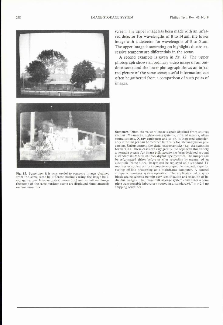
Some practical results are shown in figs 11 and 12.In fig. 11 two coincident infrared images of the samescene are shown one on top of the other on one
268 IMAGE-STORAGE SYSTEM Philips Tech. Rev. 43, No. 9
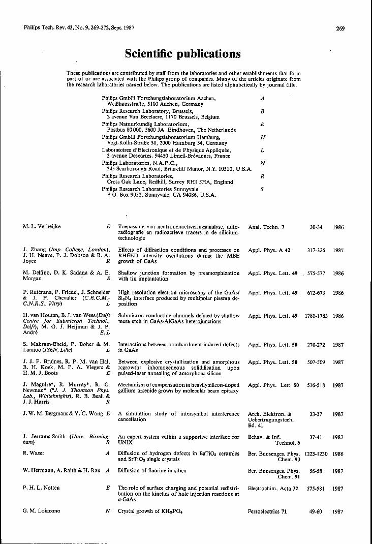
Fig. 12. Sometimes it is very useful to compare images obtainedfrom the same scene by different methods using the image bulk-storage system. Here an optical image (top) and an infrared image(bottom) of the same outdoor scene are displayed simultaneouslyon two monitors.
screen. The upper image has been made with an infra-red detector for wavelengths of 8 to 14urn, the lowerimage with a detector for wavelengths of 3 to 5 urn.The upper image is saturating on highlights due to ex-cessive temperature differentials in the scene.
A second example is given in fig. 12. The upperphotograph shows an ordinary video image of an out-door scene and the lower photograph shows an infra-red picture of the same scene; useful information canoften be gathered from a comparison of such pairs ofimages.
Summary. Often the value of image signals obtained from sourcessuch as TV cameras, night-viewing systems, infrared sensors, ultra-sound systems, X-ray equipment and so on, is increased consider-ably if the images can be recorded faithfully for later analysis or pro-cessing. Unfortunately the signal characteristics (e.g. the scanningformat) in all these cases can vary greatly. To cope with this varietya versatile system for image bulk storage has been designed arounda standard 80-Mbitfs 24-track digital tape recorder. The images canbe reformatted either before or after recording by means of anelectronic frame store. Images can be replayed on a standard TVmonitor or copied on to a computer-compatible magnetic tape forfurther off-line processing on a mainframe computer. A controlcomputer manages system operation. The application of a sync-block coding scheme permits easy identification and selection of in-dividual images. The image bulk-storage system constitutes a com-plete transportable laboratory housed in a standard (6.7 m x 2.4 m)shipping container.
Philips Tech. Rev. 43, No. 9, 269-272, Sept. 1987
These publications are contributed by staff from the laboratories and other establishments that formpart of or are associated with the Philips group of companies. Many of the articles originate fromthe research laboratories named below. The publications are listed alphabetically by journal title.
Philips GmbH Forschungslaboratorium Aachen, AWeillhausstraJ3e, 5100 Aachen, Germany
Philips Research Laboratory, Brussels, B2 avenue Van Becelaere, 1170 Brussels, Belgium
Philips Natuurkundig Laboratorium, EPostbus 80000, 5600 JA Eindhoven, The Netherlands
Philips GmbH Forschungslaboratorium Hamburg, HVogt-Kölln-StraBe 30, 2000 Hamburg 54, Germany
Laboratoires d'Electronique et de Physique Appliquée, L3 avenue Descartes, 94450 Limeil-Brévannes, France
Philips Laboratories, N.A.P.C., N345 Scarborough Road, Briarcliff Manor, N.Y. 105lO, U.S.A.
Philips Research Laboratories, RCross Oak Lane, RedhilI, Surrey RHI 5HA, England
Philips Research Laboratories Sunnyvale SP.O. Box 9052, Sunnyvale, CA 94086, U.S.A.
M. L. Verheijke
Scientific publications
269
E Toepassing van neutronenactiveringsanalyse, auto- Anal. Techn. 7radiografie en radioactieve tracers in de silicium-technologie
1986
J. Zhang (Imp. College, London),J. H. Neave, P. J. Dobson & B. A.Joyce R
M. Delfino, D. K. Sadana & A. E.Morgan > S
P. Rutérana, P. Friedel, J. Schneider& J. P. Chevalier (C.E.C.M.-C.N.R.S., Vitry) L
H. van Houten, B. J. van Wees (DelftCentre for Submicron Techno/.,Delft), M. G. J. Heijman & J. P.André E, L
S. Makram-Ebeid, P. Boher & M.Lannoo (ISEN, Lille) L
J. J. P. Bruines, R. P. M. van Hal,B. H. Koek, M. P. A. Viegers &H. M. J. Boots E
J. Maguire*, R. Murray*, R. C.Newman* (*J. J. Thomson Phys.Lab., Whiteknights), R. B. Beall &J. J. Harris R
J. W. M. Bergmans & Y. ·C.Wong E
J. Jerrams-Smith (Univ. Birming-ham) R
R. Waser
Effects of diffraction conditions and processes onRHEED intensity oscillations during the MBEgrowth of GaAs
Shallow junction formation by preamorphizationwith tin implantation
High resolution electron microscopy of the GaAs!SisN4 interface produced by multipolar plasma de-position
Submicron conducting channels defined by shallowmesa etch in GaAs-AlGaAs heterojunctions
Interactions between bombardment-induced defectsin GaAs
Between explosive crystallization and amorphousregrowth: inhomogeneous solidification uponpulsed-laser annealing of amorphous silicon
Mechanism of compensation in heavily silicon-dopedgallium arsenide grown by molecular beam epitaxy
A simulation study of intersymbol interferencecancellation
An expert system within a supportive interface forUNIX
A Diffusion of hydrogen defects in BaTiOs ceramicsand SrTiOs single crystals
W. Hermann, A. Raith & H. Rau A Diffusion of fluorine in silica
P. H. L. Notten
30-34
Appl. Phys. A 42 317-326 1987
Appl, Phys. Lett. 49 575-577 1986
Appl. Phys. Lett. 49 672-673 1986
Appl. Phys. Lett. 49 1781-1783 1986
Appl. Phys. Lett. 50 270-272 1987
Appl. Phys. Lett. 50 507-509 1987
Appl, Phys. Lett. 50 516-518 1987
Arch. Elektron. & 33-37Uebertragungstech.Bd.41
1987
Behav. & Inf. 37-41Technol. 6
Ber. Bunsenges. Phys, 1223-1230 1986Chem.90
1987
Ber. Bunsenges. Phys.Chem.91
56-58 1987
E The.role of surface charging and potential redistri- Electrochim. Acta 32 575-581 1987bution on the kinetics of hole injection reactions atn-GaAs
G. M. Loiacono N Crystal growth of KH2P04 Ferroelectrics 71 49-60 1987
270
A. Bhattacharyya, J. D. Reimer &K. N. Ritz S
SCIENTIFIC PUBLICATIONS
Breakdown voltage characteristics of thin oxidesand their correlation to defects in the oxide asobserved by the EBIC technique
F. L. van Nes (Inst. Perception Res., A new teletext character set with enhanced legibilityEindhoven)
A. Bhattacharyya&S. N. Shabde S Degradation of short-channel MOSFET's underconstant current stress across gate and drain
A. W. Ludikhuize
P. Piret
P. Delsarte & P. Piret
P. van Weijer
E A versatile 250/300-V IC process for analog andswitching applications
B Bounds for codes over the unit circle
B Do most binary linear codes achieve the Goblickbound on the covering radius?
E Pulsed optical pumping as a tool for thedetermination of population mechanisms of excitedstates in a low-pressure mercury discharge
A. G. Dirks, T. Tien & J. M. Towner Al-Ti and Al-Ti-Si thin alloy filmsS
K. N. Ritz, M. Delfino, C. B. CooperHl" & R. A. Powell" (. Varian Res.Center, PaloAlto, CA) S
J. Khurgin, B. J. Fitzpatrick & W.Seemungal N
G. J. van Gurp, P. R. Boudewijn, M.N. C. Kempeners & D. L.A. Tjaden E
P. J. Schoenmakers, F. C. C. J. G.Verhoeven & H. M. van den Bogaert
E
P. J. Schoenmakers & T. BlaffertE,H
C. Guedon, J. Le Bris & J. L.Gentner L
E. P. Menu, D. Moroni, J. N.Patillon, T. Ngo & J. P. André L
P. J. Dobson, B. A. Joyce, J. H.Neave & J. Zhang (Imp. College,London) R
J. Aarts, W. M. Gerits & P. K.Larsen E
P. F. Fewster, J. P. Gowers, D.Hilton &C. T. Foxon R
K. Woodbridge, J. P. Gowers, P. F.Fewster, J. H. Neave &B. A. JoyceR
Observation of slip dislocations in (100) siliconwafers after BF2 ion implantation and rapid thermalannealing
Cathodoluminescence, gain, and stimulated emis-sion in electron-beam-pumped ZnCdSe
Zinc diffusion in n-type indium phosphide
Application of supercritical fluid chromatography tothe analysis of liquid-crystal mixtures
Effect of model inaccuracy on selectivity optimi-zation procedures in reversed-phase liquid chroma-tography
Control of interface formation during growth ofInGaAs/lnP heterostructures by chloride vapourphase epitaxy
High mobility of two-dimensional electrons inGal_xlnxAs/lnP heterostructures grown byatmospheric pressure MOVPE
Current understanding and applications of theRHEED intensity oscillation technique
Monolayer and bilayer growth on Ge(I11)
Structural studies of GaAs-AlAs superlattices grownbyMBE
RHEED studies and interface analysis of GaAsgrown on Si(OOI) .
Philips Tech. Rev. 43, No. 9
IEEE EDL-7 58-60 1986 .
IEEE Trans. ED-33 1222-1225 1986
IEEE Trans. ED-33 1329-1333 1986
IEEE Trans. ED-33 2008-2015 1986
IEEE Trans. IT-32 760-767 1986
IEEE Trans. IT-32 826-828 1986
IEEE Trans. PS-14 464-470 1986
J. Appl. Phys. 59
J. Appl. Phys. 60
J. Appl. Phys. 61
J. Appl. Phys. 61
J. Chromatogr. 371
J. Chromatogr. 384
J. Cryst. Growth 79
J. Cryst. Growth 79
J. Cryst. Growth 81
J. Cryst. Growth 81
J. Cryst. Growth 81
J. Cryst. Growth 81
E. T. J. M. Smeets E Solid composition of GaAS1-xPxgrown by organo- J. Cryst. Growth 82metallic vapour phase epitaxy
A. H. van Ommen, M. F. C.Willemsen, A. E. T. Kuiper & F. H.P. M. Habraken (Univ. Utrecht) E
E. K. Broadbent, A. E. Morgan,J. M. DeBlasi, P. van der Putte,B. Coulman, B. J. Burrow, D. K.Sadana&A. Reader E,S
M. Delfino, D. K. Sadana, A. E.Morgan & P. K. Chu (C. Evans &Associates, San Mateo, CA) S
Etch rate modification of SisN4 layers by ionbombardment and annealing
Growth of selective tungsten on self-aligned Ti andPtNi silicides by low pressure chemical vapordeposition
A study of atomic and molecular arsenic ion-implanted silicon
2010-2014 1986
800-802 1986
1606-1609 1987
1846-1855 1987
121-134 1986
117-133 1987
909-913 1986
920-927 1986
1-8 1987
65-66 1987
120 1987
224-225 1987
385-395 1987
J. Electrochem. Soc. 2140-2147 1984131
J. Electrochem. Soc. 1715-1721 1986133
J. Electrochem. Soc. 1900-1905 1986133
Philips Tech. Rev. 43, No. 9
P. H. L. Notten& J. J. Kelly
D. M. de Leeuw, T. Kovats & S. P.Herko N
P. K. Bachmann, P. Geittner, D.Leers &H. Wilson A
P. Geittner, H. J. Hagemann, J.Warnier&H. Wilson A
P. K. Bachmann, D. Leers, H. Wehr,D. U. Wiechert, J. A. van Steenwijk,D. L. A. Tjaden & E. R. Wehrhahn(Philips Kommunikations Industrie,Nürnburg) A,E
H. J. G. Draaisma*, W. J. M. deJonge* (*Univ. of Technoi., Eind-hoven) &F. J. A. den Broeder E
A. Bhattacharyya & C. Vorst
SCIENTIFIC PUBLICATIONS
E Evidence for cathodic proteetion of crystallographicfacets from GaAs etching profiles
Kinetics of photostimulated luminescence inBaFBr:Eu
Loss reduction in fluorine-doped SM- and high N.A.-PCVD fibers
PCVD at high deposition rates
Dispersion-flattened single-mode fibers preparedwith PCVD: performance, limitations, designoptimization
Magnetic interface anisotropy In Pd/Co and Pd/Femultilayers
271
J. Electrochem. Soc. 444-448 1987134
J. Electrochem. Soc. 491-493 1987134
J. Lightwave Technol. 813-817 1986LT-4
J. Lightwave Technol. 818-822 1986LT-4
J. Lightwave Technol. 858-863 1986LT-4
J. Magn. & Magn. 351-355 1987Mater. 66
S Effect of addition of TCA (trichloroethane) on the J. Phys. D 19- electrical properties of thin oxides processed by atwo-step oxidation technique
L161-L166 1986
M. J. Keesman, P. H. G. Offermans&E. P. Honig E
M. Delfino & P. K. Chu (C.Evans &Associates, San Mateo, CA) S
G. J. Campisi, H. B. Dietrich (NavalRes. Lab., Washington, DC), M.Delfino & D. K. Sadana S
W. G. M. van den Hoek
W. G. M. van den Hoek
J. M. DeBlasi, D. K. Sadana & M.H. Norcott S
S. Aronowitz* & M. Delfino(*Fairchild Res. Center, Palo Alto,CA) S
Silica gel formation followed by dynamic shearexperiments
Donor creation during oxygen implanted buriedoxide formation
High dose implantation of nickel into silicon
S The etch mechanism for AL20a in fluorine andchlorine based RF dry etch plasrnas
S Characterization of plasma-enhanced chemicalvapour deposition of silicon-oxynitride
Interfacial tunnel structures in CMOS source/drainregions following selective deposition of tungsten
Laser activated glass flow modeling
Mater. Lett. 5 140-142 1987
Mater. Res. Soc. 245-250 1986Symp, Proc. 53
Mater. Res., Soc. 747-752 1986Symp. Proc. 54
Mater. Res. Soc. 71-78 1986Syrnp. Proc. 68
Mater. Res. Soc. 335-342 1986Symp, Proc. 68
Mater. Res. Soc. 303-308 1986Symp. Proc. 71
Mater. Res. Soc. 479-485 1986Symp. Proc. 71
A. L. J. Burgmans E IC-technologie op submicron-niveau; een CMOS- Ned. T. Natuurk. A 99-102 1986proces 52
F. M. Klaassen E Fysica van kleine IC-componenten Ned. T. Natuurk. A 107-112 198652
P. C. Zalm, A. W. Kolfschoten, Surface processes in ion-induced etchingF. H. M. Sanders&P. Vischer E
H. J. Ligthart, E. Gerritsen, P. J. Aluminium implantations in coppervan den Kerkhoff, S. Hoekstra, R. E.van de Leest & E. Keetels E
A. H. van Ommen, M. F. C. Willem- The effect of ion beam mixing on MoSi2 formationsen & R. A. M. Wolters E
R Accuracy of the transmission coefficient across Phys, Stat. Sol. b 139 573-582 1987parabolic barriers as obtained from a generalizedWKB approach
E Electromagnetic compatibility Phys. Technol. 18 61-67 1987
C. W. J. Beenakker
M. A. Brummell*, R. J. Nicholas*,-M. A. Hopkins* (*Clarendon Lab.,Oxford), J. J. Harris&C. T. Foxon R
F. Berz & J. A. Morice
J. J. Goedbloed
E Evolution of two-dimensional soap-film networks
Modification of the electron-phonon interactions inGaAs-GaAlAs heterojunctions
Nucl. Instrurn. & 625-628 1987Methods Phys. Res.
B18
Nucl. Instrurn. & 209-212 1987Methods Phys. Res.
B19/20
Nucl. Instrurn. & 742-745 1987Methods Phys. Res.
B19/20
Phys. Rev. Lett. 57
Phys. Rev. Lett.58
2454-2457 1986
77-80 1987
H. W. A. M. Rompa, R. Eppenga & Ab initio determinations of oscillator strengths of Physica 145BM. F. H. Schuurmans E metals and semiconductors from ASW
5-15 1987
272
W. F. Druyvesteyn, A. J. M. Kaizer,D. J. Verschuur= & D. de Vries·(·Univ. of Techno/., Delft) E
V. Pauker
D. Meignant (RTC Compe/ec,Limeil-Brëvannesï, E. Delhaye & M.Rocchi L
T. Ducourant, M. Binet, J.-C.Baelde, C. Rocher, J.-M. Gibereau L
P. A. Gough, M. R. Simpson & V.Rumennik N
S. Mukherjee, C. J. Chou, K. Shaw,D. McArthur& V. Rumennik N
C. A. M. Mulder &G. Frens
SCIENTIFIC PUBLICATIONS
Wigner representation of loudspeaker responses in aliving room
L GaAs monolithic microwave active gyrator
A 0.1 - 4.5 GHz, 20 mW GaAs prescaIer operatingat 125°C
3 GHz, 150 mW, 4 bit GaAs analogue to digitalconverter
Fast switching lateral insulated gate transistor
The effects of SIPOS passivation on DC andswitching performance of high voltage MOStransistors
E The incorporation of fluorine in vitreous silica
J. Hightower, M. Blanco, M. Cagan An application of statistical experimental design:&K. Monahan S comparison of process latitudes for photoresist and
cel
U. Schiebel, W. Hillen & T. Zaengel Image quality in selenium-based digital radiographyA
Philips Tech. Rev. 43, No. 9
Proc. ABS Conv.,London 1987(preprint)
Proc. GaAs IC Symp.,Grenelefe, FL, 1986
Proc. GaAs IC Symp.,Grenelefe, FL, 1986
Proc. GaAs IC Symp.,Grenelefe, FL, 1986
Proc. IEDM 86, LosAngeles, CA, 1986
Proc. IEDM 86, LosAngeles, CA, 1986
12pp. 1987
82-85 1986
129-132 1986
209-212 1986
218-221 1986
646-649 1986
Proc. 1st Int. Work- 259-265 1986shop on Non-crystal-line solids, San Feliude Guixols 1986
Proc. Kodak Micro-electron. Seminar,San Diego, CA, 1985
Proc. SPIE 626
P. J. Severin E Passive components for multimode fibre-optic Proc. SPIE 630networks
M. Erman, N. Vodjdani, P. Jarry, P.Stéphan, J. L. Gentner & C. Guedon
L
W. S. Newman & N. Hogan (Massa-chusetts Inst. of Techno/., Cam-bridge, MA) N
A. G. Dirks & J. J. van den Broek E
D. E. Lacklison &P. Capper
A. F. Deutz", H. B. Brom", H.Deelen", L. J. de Jongh*, W. J.Huiskamp* (·Univ. Leiden) & K. H.J. Buschow E
P. W. J. M. Boumans & J. J. A. M.Vrakking E
C. W. T. Bulle-Lieuwma & P. C.Zalm E
E. E. Havinga & L. W. van HorssenE
A. G. Tangena
111-V semiconductor waveguides and phase-modula-tors: the localized vapor phase epitaxy approach
The optimal control of balanced manipulators
Precipitation from metastable solid solutions in alu-minum rich AL-V thin films
R Hall effect measurements on Bridgman-grownCdxHgl-x Te and their analysis
Induced-moment ferromagnetic ordering in the sing-let ground state compound TmNi2
Detection limits of about 350 prominent lines of 65elements observed in 50 and 27 MHz inductivelycoupled plasrnas (ICP): effects of source characteris-tics, noise and spectral bandwidth-'Standard'values for the 50 MHz ICP
E
Suppression of surface topography development inionmilling of semiconductors
Influence of chain length and structural order on theelectrical conductivity of poly-p-phenylenes heavilydoped with potassium
Tribology of thin film systems
Contents ofPhilips Telecommunication and Data Systems Review 45, No. 1, 1987
A. Brinkman: Transmation: Electronics improving public transport (pp. 2-15)
J. Goris & J. Veldman: The Rotterdam Vessel Traffic Management System (pp. 16-33)
C. Viret: Trends in civil avionics for the near future (pp. 34-41)
Proc. SPIE 651
Robotics 3
Scr. Metall. 21
39-49 1985
176-184 1986
98-109 1986
75-82 1986
177-184 1987
175-180 1987
Semicond. Sci. Tech- 136-144 1987nol. 2
Solid State Commun.60
Spectrochim. Acta428
Surf. & InterfaceAnal.10
Synth, Met. 17
Thesis, Eindhoven
917-921 1986
553-579 1987
210-215 1987
623-628 1987
1-129 1987
Volume 43, No. 9 pages 233-272 Published 23th September 1987