Embed Size (px)
Citation preview
A Model Based Design Approach To System Building Using The e-Yantra Educational Robot
Kavi Arya CSE Dept., IIT Bombay
Powai, Mumbai 400076 India +91-22-25767909
Blossom Coelho IIT Bombay
Powai, Mumbai 400076 India +91-22-225708681
Shraddha Pandya IIT Bombay
Powai, Mumbai 400076 India +91-22-22804926
ABSTRACT The e-Yantra robot is the basis for a highly scalable embedded systems teaching program setting up 500 embedded systems labs in Indian engineering colleges. A key strategy to encourage rapid prototyping of applications has been to encourage reuse of code using a commodity robot with a standard API along with excellent documentation and training material. An important challenge has been to teach the reasoning process from a design through to an implementation deployed on an actual machine. Model based design is key to articulating such reasoning. A further challenge is to do this in an affordable manner where most available model-based IDEs are expensive proprietary systems using languages such as Esterel and SCADE. We illustrate with a “Valet Parking” application how our robotic eco-system facilitates the learning of important model-based design principles taking a high-level specification of a problem down to working code and even deriving test cases in the process. A novel feature of our approach is that we carry out design-time scheduling of various (concurrent) activities by analyzing dependencies between modules and obtain purely sequential C-code implemented on a microcontroller without the need for an RTOS. This case study is an exemplar of a model-based design approach for a large class of such robotic projects.
Categories and Subject Descriptors C. [Computer System Organisation] C.3 [Special Purpose & Application Based System] Realtime & Embedded System. D.2 [Software Engineering]: D.2.1 Requirements /specification; D.2.2 Design Tools & Techniques, D.4.7 Organisation & Design; K.3 [Computers & Education]: K.3.1 Computer Uses in Education;
General Terms Design, Reliability, Experimentation, Standardization, Languages, Verification.
Keywords Project Based Learning, Educational Robot, Model Based Design, UML, State Machines. Design Time Scheduling. Model Based Testing.
1. INTRODUCTION Whereas many students wish to study Embedded Systems and Robotics, in India they are stymied by the lack of a suitable robotic eco-system. Imported robots are either too expensive or unsupported. What started as a project to develop a simple
educational robot to teach embedded systems has evolved into a program developing a robotic eco-system.
In section 2 we describe the e-Yantra project that is building the eco-system around this robot. E-Yantra is tasked to set up 500 labs in 3 years. In this, it’s first year we will have set up 120 labs. With this eco-system in place we are in a position to train a large number of students in building interesting final-year projects that would have not been possible till now. This is because we encourage the reuse of code from earlier projects in order to focus on “higher level” goals. The key goal is to be able to rapidly prototype complex applications out of simpler components. Model based design provides an adequate framework to carry this out. UML is a mature model based design framework. An important higher-level goal is to use the platform to teach such “Model Based Design,” which is the theme of current paper. In Section 3, we briefly describe the robot that constitutes the platform for our robotic eco-system development in the e-yantra project.
We illustrate here the possibilities created by this project by presenting the final year project of a pair of students registered for a Computer Science program [6]. We suggest that this project would not have been possible had it not been for the infrastructure and assistance provided by e-Yantra. The project serves as an exemplar for more such work teaching students “Model Based Design” and component based design skills using a “Project Based Learning (PBL)” approach. We illustrate this through the model-based design of a Valet Parking System using the e-Yantra robot. We give the requirements specification of the problem in section 4. In section 5 we present the high-level and detailed design of the system. Section 6 presents system integration and coding. In section 7 we illustrate the model based testing of the Valet Parking System. We conclude with our observations in section 8.
2. e-YANTRA PROJECT e-Yantra is a project entitled “Robot Enabled Teaching in Engineering Colleges” [1, 2] with the mission of spreading “Project Based Learning (PBL) as a national mission throughout engineering education in India. It is the brainchild of Prof. Kavi Arya (PI, e-Yantra) and Prof. Krithi Ramamritham at IIT-Bombay arising of an attempt to teach Embedded Systems (PG & UG) through the Distance Education Program of IIT-Bombay since 2003. We found that whereas theoretical subjects are easier to teach through a MOOCS-like framework, Project Based Learning is more difficult, requiring both adequately equipped labs and trained teachers– both of which are in acutely short supply in the country. It was believed that if we were to package a lab “in a box” and make recorded lectures available along with other Authors retain copyright.
material that even a practical subject such as Embedded Systems can be taught. Following its initial successful pilot phase starting in 2011, E-Yantra has evolved into a program targeted at setting up 500 labs throughout the country in 3 years. It has refined the process of setting up a lab and training 4 teachers per college in Project Based Learning in four months through a highly scalable model [1].
3. THE FIREBIRD ROBOT The Firebird V is e-Yantra's educational and research robot developed by the Embedded and Real-time Systems (ERTS) laboratory of IIT Bombay. The robot provides the functionality and hardware for us to conveniently develop our Valet Parking application. We contend in this paper that the clean API developed with this robot facilitated its use as a platform to implement controllers designed using “Model Based Design.” In 3.1 we illustrate the (extensible) feature set of our robot along with the software eco-system around it.
Figure 1. Fire Bird V Robot
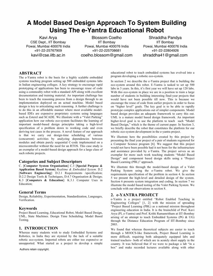
Figure 2. Block Diagram of Fire Bird V Robot [3]
3.1 Technical Specification of Fire Bird V The microcontroller is an Atmel ATMEGA2560 as a Master with Atmel ATMEGA8 as a Slave microcontroller. Sensors: Three white line sensors (extendable to 7); 5 Sharp GP2Y0A02YK IR range sensor; 8 analog IR proximity sensors; 2 position encoders (extendable to 4); battery voltage sensing; Indicators: 2 x 16 Characters LCD; Indicator LEDs; Buzzer. Control by:
Autonomous Control; with PC as “Master” and robot as “Slave” in wired or wireless mode; Distributed (multi robot) communication. Communication: USB Communication: Wired RS232 (serial) communication. Dimensions: Diameter: 16cm; Height: 10cm: Weight: 1300gms. Power: 9.6V, 2100mAh Nickel Metal Hydride (NiMH) battery pack and external Auxiliary power using battery charger; Locomotion: Two DC geared motors in differential drive configuration and caster wheel at front as support; Top Speed: 24 cm / second; Wheel Diameter: 51mm; Position encoder: 30 pulses per revolution. Software Support: AVR Studio; GUI based control; Microsoft Robotic Developer Studio (MRDS); MATLAB/SCILAB; Programming language – C. Win AVR; GCC; AVR Bootloader. Most work is typically done with Open Source tools. An evaluation version of the UML development environment Visual Paradigm was used in the current project.
The Firebird-5 manuals [3,4] and tutorials [5] provide a good introduction to the robot. The features of the robot have also been provided as an API that forms the basis for our work.
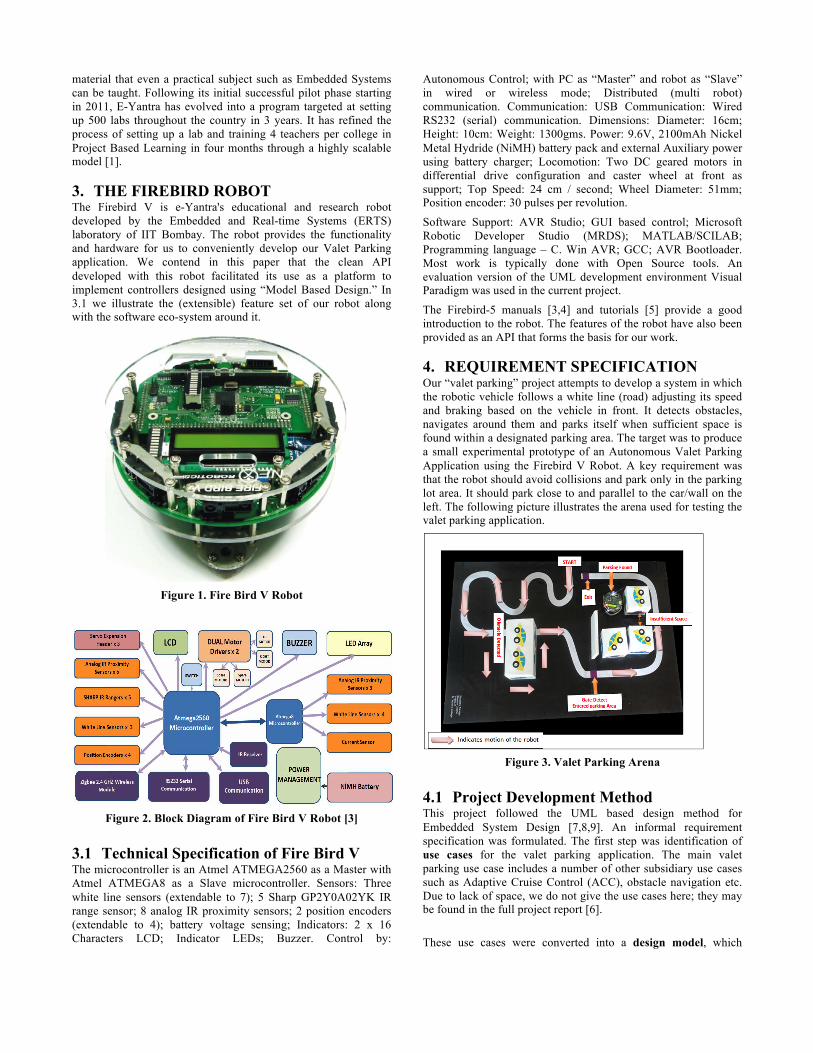
4. REQUIREMENT SPECIFICATION Our “valet parking” project attempts to develop a system in which the robotic vehicle follows a white line (road) adjusting its speed and braking based on the vehicle in front. It detects obstacles, navigates around them and parks itself when sufficient space is found within a designated parking area. The target was to produce a small experimental prototype of an Autonomous Valet Parking Application using the Firebird V Robot. A key requirement was that the robot should avoid collisions and park only in the parking lot area. It should park close to and parallel to the car/wall on the left. The following picture illustrates the arena used for testing the valet parking application.
Figure 3. Valet Parking Arena
4.1 Project Development Method This project followed the UML based design method for Embedded System Design [7,8,9]. An informal requirement specification was formulated. The first step was identification of use cases for the valet parking application. The main valet parking use case includes a number of other subsidiary use cases such as Adaptive Cruise Control (ACC), obstacle navigation etc. Due to lack of space, we do not give the use cases here; they may be found in the full project report [6].
These use cases were converted into a design model, which
comprises of several UML state machines [11,12]. In the implementation stage, the design model was systematically converted into sequential C-code. The principles behind this transformation constitute an important element of learning embedded systems programming. The key artifact in this method was the state machine based design model. Model based testing of the application ensuring 100% transition coverage of the model was also carried out.
Each state machine embodies a subsystem for which interface signal and conditions by which it interacts with other subsystems/environment are also designed [8,9]. The collection of state machines constitutes a high level model of the application controller. In addition, the design includes a platform dependent sensor and actuator module, which interfaces the high level controller with the physical sensors/actuators. A substantial portion of this sensor/actuator subsystem can be standardized in to a platform specific API for the firebird, which can be reused across projects.
The UML state machines are hierarchical and concurrent, and they interact by broadcast of triggering events [11,12]. These powerful mechanisms allow component models to be adapted and integrated in a compositional manner to give the overall application. The design can be carried out in an incremental fashion by adding functionality in a spiral model of development and testing. It is our belief that UML state machines allow construction of embedded software from reusable components,
UML state machines provide a high level design model of the controller. Constructing such a design model has several important functions.
• The high level model embodies the “logic” of the multimodal discrete controller. Even a simple application such as valet parking exhibits complexities of interaction between multiple features of the application and model helps in visualizing these.
• The state machine based model is executable and it can be used to simulate the design and gain confidence.
• Model based test case generation can be undertaken. Criteria such as state coverage and transition coverage can be used to evaluate efficacy of the test suite.
• Code can be generated from the model in a systematic fashion to ensure that the implementation conforms to the model.
We now describe the main steps in the design of the valet parking controller program. The first step was the top-level design of the state machine for valet parking controller (see Figure 5. Valet Parking State Machine). The system was decomposed into four modules namely (1) Find Parking, (2) Obstacle Navigation, (3) Do Parking, and (4) Exit. The transitions that switch control between these modules were designed. The Find Parking module was further decomposed into a concurrent composition of four sub-modules, namely (1) Gate detect, (2) Parking Detect, (3) Adaptive Cruise Control, and (4) White ine Follower (see Figure 6). Interfaces (signals and conditions) were designed by which these modules communicate with each other. In the detailed design phase, the state machines of these individual modules were elaborated. Finally, each state machine was converted into C code. In system integration phase, the C code for each module was combined into a single program having required functionality.
The spiral model of software development was used in the project. In the first iteration, the white line follower module was designed
and implemented. In the next iteration adaptive cruise control functionality was added. In the third iteration, do-parking function was developed. Moreover, parking-detection module was also developed and both these modules were integrated to give an application, which finds and carries out parking. In the next iteration, obstacle navigation module was developed. This was a major effort. Finally, in the last iteration, gate detection and exit modules were developed and integrated with the application. In each iteration, testing was undertaken to ensure 100% transition coverage of the state machine model relevant to that iteration.
4.2 Software Tools Used UML Modelling- Visual Paradigm: C-programming IDE - AVR Studio, WinAVR with GCC C compiler, AVR Boot Loader. Firebird robot is based upon ATMEL Atmega 128 microcontroller which belongs to AVR series. There are lots of IDEs available for the AVR microcontrollers. In our project we focused on the studio from the ATMEL. It uses WIN AVR open source C compiler at the back end. After writing and compiling the program it gives a “.hex” file which we load on the robot using an In-System Programmer (ISP). The controller model was built
5. HIGH LEVEL DESIGN We illustrate in 5.1 elements of our API that abstracts the sensors and actuators of our robot and introduce the partitioned controller. In 5.2 we detail the Valet Parking Controller based on the feature-set available. IN 5.3 we detail the “Find Parking” module used by the overall controller.
5.1 Sensors, Actuators and Controller The valet parking system works in a time triggered manner executing repeated sense, compute, react loop at fixed time intervals. In each iteration of the loop, the sensor values are read and these are interpreted as logical sensor conditions. For example, the three white line sensors are read, and based on their value; the sensor subsystem indicates which of the following logical conditions are true or false.
• WL_MIDDLE – All 3 sensors are white and hence robot is in middle of the road
• WL_LEFT – Left sensor is black (off road) and remaining two sensors are white, indicating robot is slightly left of road.
• WL_OUT – all three sensors are black and robot is off the road.
It is the job of sensor subsystem to acquire the current sensor readings and to convert these into such logical input conditions. In response to these conditions, the robot may make a decision to perform some logical output function on the actuators. The decision making is carried out in the digital controller.
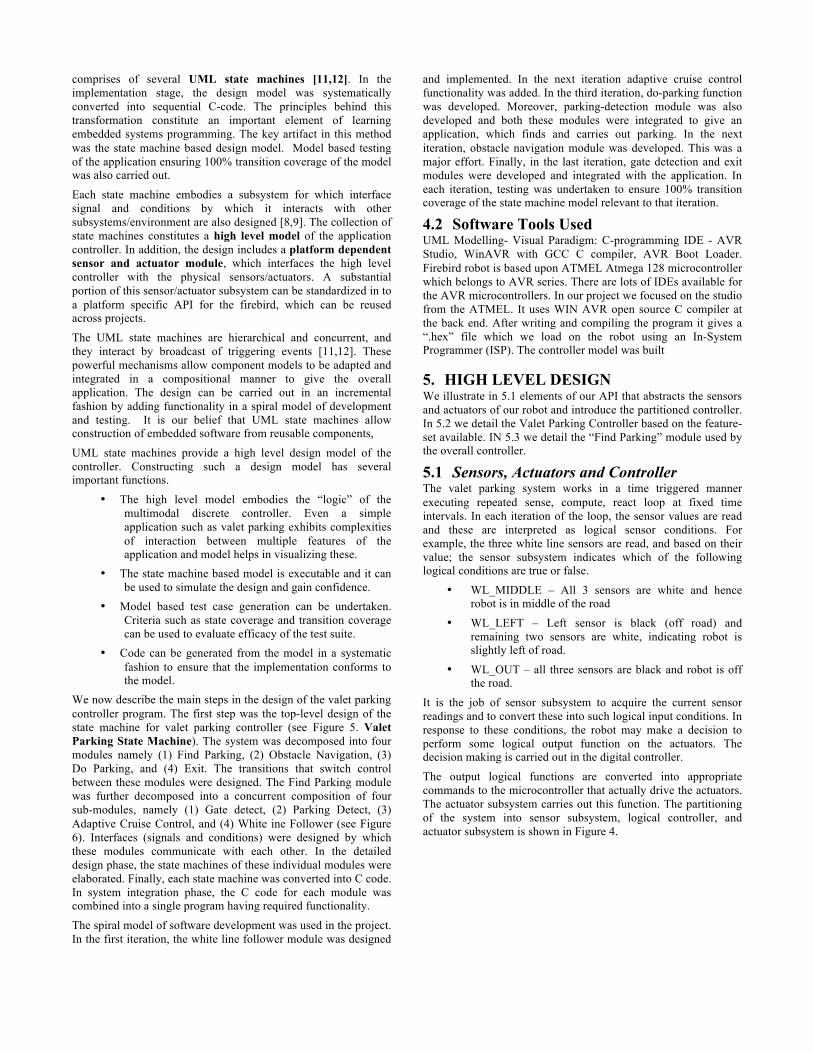
The output logical functions are converted into appropriate commands to the microcontroller that actually drive the actuators. The actuator subsystem carries out this function. The partitioning of the system into sensor subsystem, logical controller, and actuator subsystem is shown in Figure 4.
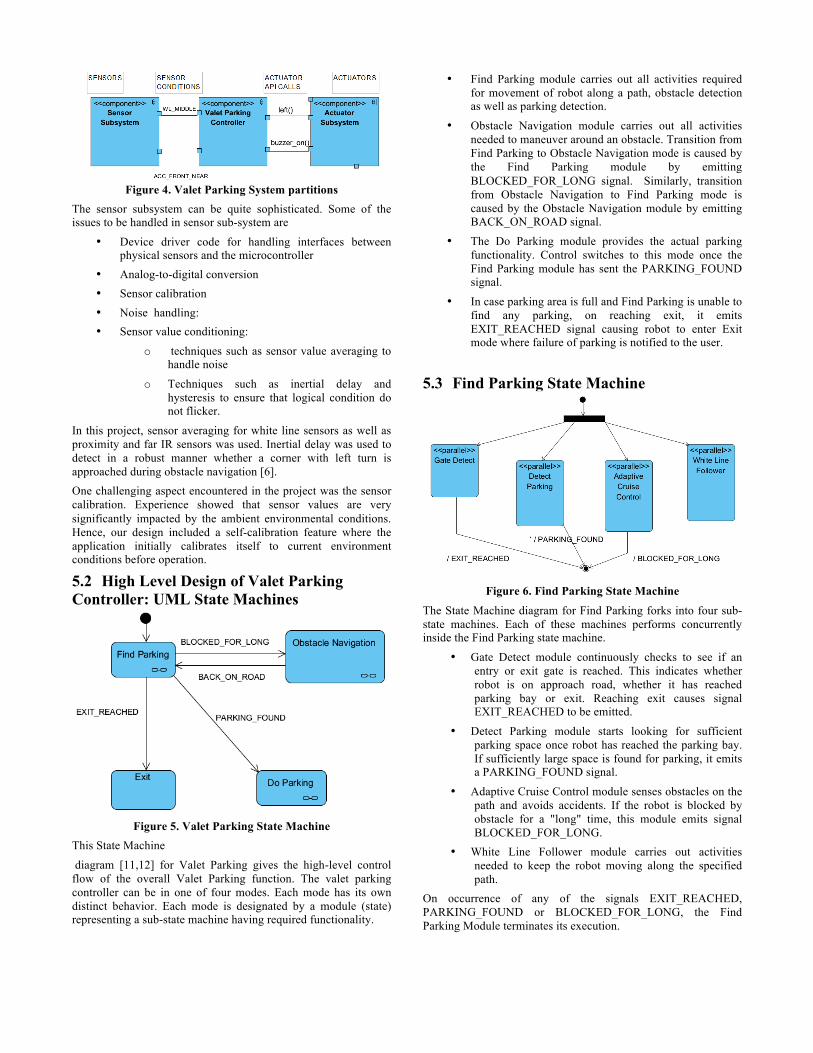
Figure 4. Valet Parking System partitions
The sensor subsystem can be quite sophisticated. Some of the issues to be handled in sensor sub-system are
• Device driver code for handling interfaces between physical sensors and the microcontroller
• Analog-to-digital conversion • Sensor calibration • Noise handling: • Sensor value conditioning:
o techniques such as sensor value averaging to handle noise
o Techniques such as inertial delay and hysteresis to ensure that logical condition do not flicker.
In this project, sensor averaging for white line sensors as well as proximity and far IR sensors was used. Inertial delay was used to detect in a robust manner whether a corner with left turn is approached during obstacle navigation [6]. One challenging aspect encountered in the project was the sensor calibration. Experience showed that sensor values are very significantly impacted by the ambient environmental conditions. Hence, our design included a self-calibration feature where the application initially calibrates itself to current environment conditions before operation.
5.2 High Level Design of Valet Parking Controller: UML State Machines
Figure 5. Valet Parking State Machine
This State Machine
diagram [11,12] for Valet Parking gives the high-level control flow of the overall Valet Parking function. The valet parking controller can be in one of four modes. Each mode has its own distinct behavior. Each mode is designated by a module (state) representing a sub-state machine having required functionality.
• Find Parking module carries out all activities required for movement of robot along a path, obstacle detection as well as parking detection.
• Obstacle Navigation module carries out all activities needed to maneuver around an obstacle. Transition from Find Parking to Obstacle Navigation mode is caused by the Find Parking module by emitting BLOCKED_FOR_LONG signal. Similarly, transition from Obstacle Navigation to Find Parking mode is caused by the Obstacle Navigation module by emitting BACK_ON_ROAD signal.
• The Do Parking module provides the actual parking functionality. Control switches to this mode once the Find Parking module has sent the PARKING_FOUND signal.
• In case parking area is full and Find Parking is unable to find any parking, on reaching exit, it emits EXIT_REACHED signal causing robot to enter Exit mode where failure of parking is notified to the user.
5.3 Find Parking State Machine
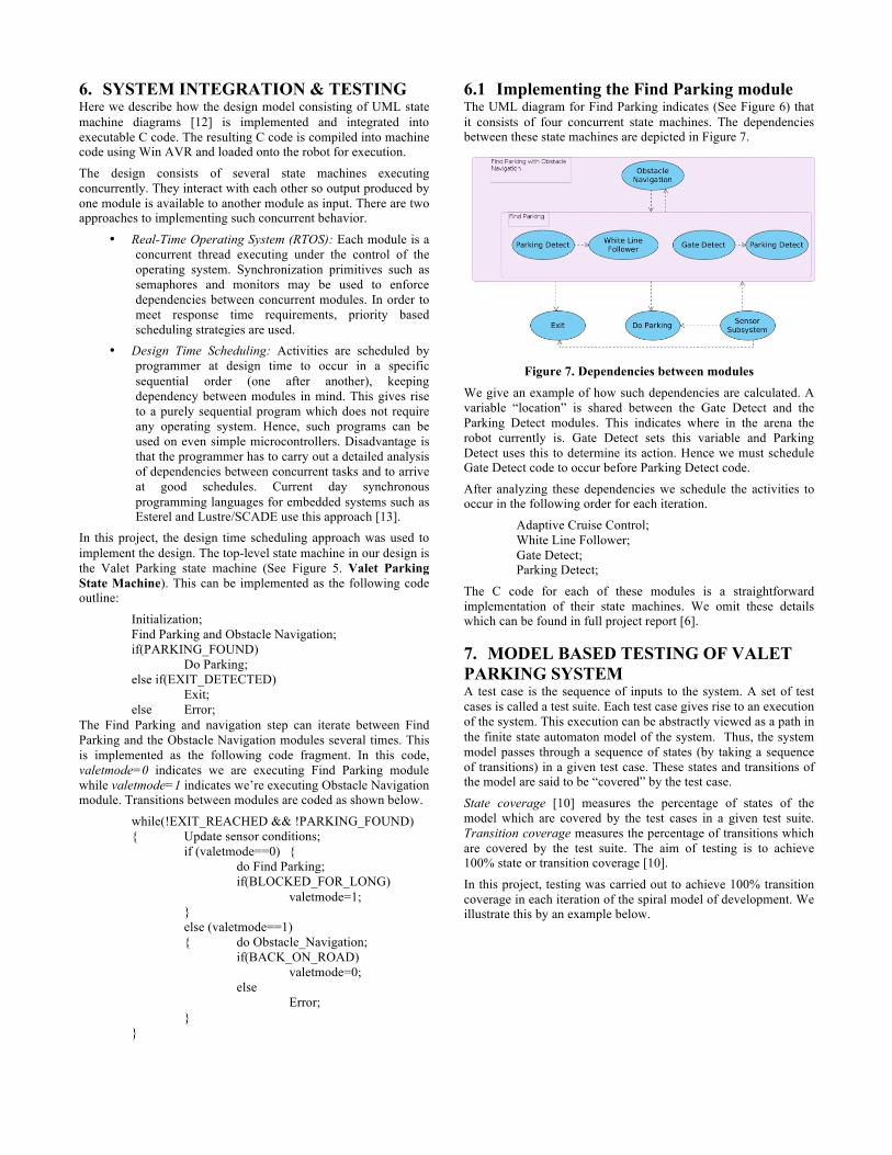
Figure 6. Find Parking State Machine
The State Machine diagram for Find Parking forks into four sub-state machines. Each of these machines performs concurrently inside the Find Parking state machine.
• Gate Detect module continuously checks to see if an entry or exit gate is reached. This indicates whether robot is on approach road, whether it has reached parking bay or exit. Reaching exit causes signal EXIT_REACHED to be emitted.
• Detect Parking module starts looking for sufficient parking space once robot has reached the parking bay. If sufficiently large space is found for parking, it emits a PARKING_FOUND signal.
• Adaptive Cruise Control module senses obstacles on the path and avoids accidents. If the robot is blocked by obstacle for a "long" time, this module emits signal BLOCKED_FOR_LONG.
• White Line Follower module carries out activities needed to keep the robot moving along the specified path.
On occurrence of any of the signals EXIT_REACHED, PARKING_FOUND or BLOCKED_FOR_LONG, the Find Parking Module terminates its execution.
6. SYSTEM INTEGRATION & TESTING Here we describe how the design model consisting of UML state machine diagrams [12] is implemented and integrated into executable C code. The resulting C code is compiled into machine code using Win AVR and loaded onto the robot for execution.
The design consists of several state machines executing concurrently. They interact with each other so output produced by one module is available to another module as input. There are two approaches to implementing such concurrent behavior.
• Real-Time Operating System (RTOS): Each module is a concurrent thread executing under the control of the operating system. Synchronization primitives such as semaphores and monitors may be used to enforce dependencies between concurrent modules. In order to meet response time requirements, priority based scheduling strategies are used.
• Design Time Scheduling: Activities are scheduled by programmer at design time to occur in a specific sequential order (one after another), keeping dependency between modules in mind. This gives rise to a purely sequential program which does not require any operating system. Hence, such programs can be used on even simple microcontrollers. Disadvantage is that the programmer has to carry out a detailed analysis of dependencies between concurrent tasks and to arrive at good schedules. Current day synchronous programming languages for embedded systems such as Esterel and Lustre/SCADE use this approach [13].
In this project, the design time scheduling approach was used to implement the design. The top-level state machine in our design is the Valet Parking state machine (See Figure 5. Valet Parking State Machine). This can be implemented as the following code outline:
Initialization; Find Parking and Obstacle Navigation; if(PARKING_FOUND) Do Parking; else if(EXIT_DETECTED) Exit; else Error;
The Find Parking and navigation step can iterate between Find Parking and the Obstacle Navigation modules several times. This is implemented as the following code fragment. In this code, valetmode=0 indicates we are executing Find Parking module while valetmode=1 indicates we’re executing Obstacle Navigation module. Transitions between modules are coded as shown below.
while(!EXIT_REACHED && !PARKING_FOUND) { Update sensor conditions; if (valetmode==0) { do Find Parking; if(BLOCKED_FOR_LONG) valetmode=1; } else (valetmode==1)
{ do Obstacle_Navigation; if(BACK_ON_ROAD) valetmode=0; else
Error; }
}
6.1 Implementing the Find Parking module The UML diagram for Find Parking indicates (See Figure 6) that it consists of four concurrent state machines. The dependencies between these state machines are depicted in Figure 7.
Figure 7. Dependencies between modules
We give an example of how such dependencies are calculated. A variable “location” is shared between the Gate Detect and the Parking Detect modules. This indicates where in the arena the robot currently is. Gate Detect sets this variable and Parking Detect uses this to determine its action. Hence we must schedule Gate Detect code to occur before Parking Detect code.
After analyzing these dependencies we schedule the activities to occur in the following order for each iteration.
Adaptive Cruise Control; White Line Follower; Gate Detect; Parking Detect;
The C code for each of these modules is a straightforward implementation of their state machines. We omit these details which can be found in full project report [6].
7. MODEL BASED TESTING OF VALET PARKING SYSTEM A test case is the sequence of inputs to the system. A set of test cases is called a test suite. Each test case gives rise to an execution of the system. This execution can be abstractly viewed as a path in the finite state automaton model of the system. Thus, the system model passes through a sequence of states (by taking a sequence of transitions) in a given test case. These states and transitions of the model are said to be “covered” by the test case.
State coverage [10] measures the percentage of states of the model which are covered by the test cases in a given test suite. Transition coverage measures the percentage of transitions which are covered by the test suite. The aim of testing is to achieve 100% state or transition coverage [10].
In this project, testing was carried out to achieve 100% transition coverage in each iteration of the spiral model of development. We illustrate this by an example below.
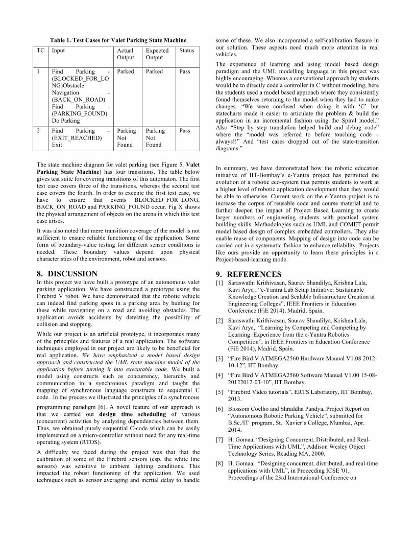
Table 1. Test Cases for Valet Parking State Machine
The state machine diagram for valet parking (see Figure 5. Valet Parking State Machine) has four transitions. The table below gives test suite for covering transitions of this automaton. The first test case covers three of the transitions, whereas the second test case covers the fourth. In order to execute the first test case, we have to ensure that events BLOCKED_FOR_LONG, BACK_ON_ROAD and PARKING_FOUND occur. Fig X shows the physical arrangement of objects on the arena in which this test case arises.
It was also noted that mere transition coverage of the model is not sufficient to ensure reliable functioning of the application. Some form of boundary-value testing for different sensor conditions is needed. These boundary values depend upon physical characteristics of the environment, robot and sensors.
8. DISCUSSION In this project we have built a prototype of an autonomous valet parking application. We have constructed a prototype using the Firebird V robot. We have demonstrated that the robotic vehicle can indeed find parking spots in a parking area by hunting for these while navigating on a road and avoiding obstacles. The application avoids accidents by detecting the possibility of collision and stopping. While our project is an artificial prototype, it incorporates many of the principles and features of a real application. The software techniques employed in our project are likely to be beneficial for real application. We have emphasized a model based design approach and constructed the UML state machine model of the application before turning it into executable code. We built a model using constructs such as concurrency, hierarchy and communication in a synchronous paradigm and taught the mapping of synchronous language constructs to sequential C code. In the process we illustrated the principles of a synchronous programming paradigm [6]. A novel feature of our approach is that we carried out design time scheduling of various (concurrent) activities by analyzing dependencies between them. Thus, we obtained purely sequential C-code which can be easily implemented on a micro-controller without need for any real-time operating system (RTOS).
A difficulty we faced during the project was that that the calibration of some of the Firebird sensors (esp. the white line sensors) was sensitive to ambient lighting conditions. This impacted the robust functioning of the application. We used techniques such as sensor averaging and inertial delay to handle
some of these. We also incorporated a self-calibration feasure in our solution. These aspects need much more attention in real vehicles.
The experience of learning and using model based design paradigm and the UML modelling language in this project was highly encouraging. Whereas a conventional approach by students would be to directly code a controller in C without modeling, here the students used a model based approach where they consistently found themselves returning to the model when they had to make changes. “We were confused when doing it with ‘C’ but statecharts made it easier to articulate the problem & build the application in an incremental fashion using the Spiral model.” Also “Step by step translation helped build and debug code” where the “model was referred to before touching code – always!!” And “test cases dropped out of the state-transition diagrams.”
In summary, we have demonstrated how the robotic education initiative of IIT-Bombay’s e-Yantra project has permitted the evolution of a robotic eco-system that permits students to work at a higher level of robotic application development than they would be able to otherwise. Current work on the e-Yantra project is to increase the corpus of reusable code and course material and to further deepen the impact of Project Based Learning to create larger numbers of engineering students with practical system building skills. Methodologies such as UML and COMET permit model based design of complex embedded controllers. They also enable reuse of components. Mapping of design into code can be carried out in a systematic fashion to enhance reliability. Projects like ours provide an opportunity to learn these principles in a Project-based-learning mode.
9. REFERENCES [1] Saraswathi Krithivasan, Saurav Shandilya, Krishna Lala,
Kavi Arya , “e-Yantra Lab Setup Initiative: Sustainable Knowledge Creation and Scalable Infrastructure Creation at Engineering Colleges”, IEEE Frontiers in Education Conference (FiE 2014), Madrid, Spain.
[2] Saraswathi Krithivasan, Saurav Shandilya, Krishna Lala, Kavi Arya, “Learning by Competing and Competing by Learning: Experience from the e-Yantra Robotics Competition”, in IEEE Frontiers in Education Conference (FiE 2014), Madrid, Spain.
[3] “Fire Bird V ATMEGA2560 Hardware Manual V1.08 2012-10-12”, IIT Bombay.
[4] “Fire Bird V ATMEGA2560 Software Manual V1.00 15-08-20122012-03-10”, IIT Bombay.
[5] “Firebird Video tutorials”, ERTS Laboratory, IIT Bombay, 2013.
[6] Blossom Coelho and Shraddha Pandya, Project Report on “Autonomous Robotic Parking Vehicle”, submitted for B.Sc./IT program, St. Xavier’s College, Mumbai, Apr. 2014.
[7] H. Gomaa, “Designing Concurrent, Distributed, and Real-Time Applications with UML”, Addison Wesley Object Technology Series, Reading MA, 2000.
[8] H. Gomaa, “Designing concurrent, distributed, and real-time applications with UML”, in Proceeding ICSE '01, Proceedings of the 23rd International Conference on
TC Input Actual Output
Expected Output
Status
1 Find Parking - (BLOCKED_FOR_LONG)Obstacle Navigation - (BACK_ON_ROAD) Find Parking - (PARKING_FOUND) Do Parking
Parked Parked Pass
2 Find Parking - (EXIT_REACHED) Exit
Parking Not Found
Parking Not Found
Pass
Software Engineering, IEEE Computer Society Washington, DC, USA, 2001, Pages 737-738.
[9] “OMG Unifiied Modelling Language”, Version 2.2, OMG Document No. 2009-02-02, OMG, (2009)
[10] ] “State-Transition Testing”, http://istqbexamcertification.com/what-is-state-transition-testing-in-software-testing/
[11] D. Harel, “Statecharts: A visual formalism for complex systems”, Science of Computer Programming, 8, (1987), pp 231-274.
[12] ] “UML State Machine Diagrams”, http://www.sparxsystems.com/resources/uml2_tutorial/uml2_statediagram.html
[13] P. Caspi et al, “Lustre a declarative language for programming synchronous systems”, in 14th ACM Symposium on Principles of Programming Languages (POPL), 1987.