Embed Size (px)
Citation preview
MASTER OF SCIENCE THESIS
A Model For Describing and Executing Test Cases Using XML
and Jini/JavaSpaces
By
Roland Ljungh
Stockholm, November 2000
Examiner and Adviser: Björn Pehrson and Vladimir Vlassov Royal Institute of Technology (KTH)
Supervisors: Roger Westerberg and Per Sjöholm Ericsson Radio Systems AB

Abstract
Abstract Ericsson Radio Systems AB is developing a new IP based GSM system. The system comprises several subsystems, or nodes. Every node must be thoroughly tested in order to verify that the functionality is correct. Since the different nodes are developed in parallel there is a need to simulate the environment surrounding the test object. These simulations are performed using various test tools, tools that are programmed to behave in a certain way. The verification of functionality, or testing, is performed manually in the sense that a programmer constructs a test program for a specific test tool, runs the test program and examines the results to verify that the requirements are reached. This thesis introduces a model for automated verification of functionality in the new IP based GSM system. The model includes a description of how test cases best are represented as well as a mechanism for distribution of test cases amongst an arbitrary number of test tools. A prototype implementation of the model was developed using test cases represented in XML and Jini and JavaSpaces as a mechanism for distribution of the test cases. The prototype implementation was evaluated in the actual test environment.


Contents
Contents 1 Introduction .................................................................................................7
1.1 Background..........................................................................................7 1.2 Problem Definition .............................................................................7 1.3 Motivation ............................................................................................7 1.4 Objective ...............................................................................................8 1.5 Structure of the Report......................................................................8
2 Test Environment.......................................................................................9 2.1 IP-BSS (Internet Protocol based Base Station Subsystem)......9
2.1.1 IP-BSS Architecture...................................................................9 2.1.2 Verification of Functionality ..................................................10
2.2 Documents Related To Testing......................................................10 2.3 Tools Used For Testing....................................................................11
3 Overview of Technologies........................................................................12 3.1 XML Introduction .............................................................................12
3.1.1 Validating XML.........................................................................13 3.1.2 Parsing XML..............................................................................13 3.1.3 Converting XML........................................................................13
3.2 SAX, DOM and JDOM.....................................................................14 3.3 Choosing XML Parser......................................................................14 3.4 XML on the Network .......................................................................15 3.5 XML Schemas and DTDs................................................................15 3.6 Jini .......................................................................................................17 3.7 JavaSpaces .........................................................................................19
4 Integration And Verification Test Model (IVTM)..............................21 4.1 Design Issues .....................................................................................21 4.2 Overview.............................................................................................21 4.3 Representation of Test Cases.........................................................22 4.4 Tool Handler ......................................................................................22 4.5 Distributing Test Cases...................................................................24 4.6 Extending the Model With A New Test Tool ..............................24 4.7 Requirements on Test Tools ...........................................................25
5 Implementation.........................................................................................26 5.1 System Overview..............................................................................26 5.2 Test Case Creation ...........................................................................29
5.2.1 Test Case Representation .......................................................29 5.2.2 Generating XML .......................................................................30 5.2.3 The Test Case Document ........................................................30 5.2.4 The Report Document ..............................................................33 5.2.5 The DTD Generator .................................................................33 5.2.6 Future Improvements..............................................................34
5.3 Execution of Test Cases...................................................................35 5.3.1 Execution....................................................................................35 5.3.2 Report Creation.........................................................................36 5.3.3 Communication Mechanisms and Leasing .........................37
Contents
6 Evaluation..................................................................................................38 6.1 Describing test cases in XML.........................................................38 6.2 XML Editors.......................................................................................39 6.3 The Distribution Mechanism .........................................................39
7 Conclusions and Future Work ...............................................................41 8 References...................................................................................................42 Appendix A: Class Diagrams .........................................................................44 Appendix B: User Manual ..............................................................................46

Introduction
7
1 Introduction
1.1 Background The M.Sc. thesis project called “A Model for Describing and Executing Test Cases Using XML and Jini/JavaSpaces” was done at Ericsson Radio Systems AB in Stockholm during the Autumn 2000. The objective was to develop a model for test case execution that allows automated testing and to implement part of the model as a case study.
1.2 Problem Definition Ericsson Radio Systems AB is developing a new IP based GSM system. The system comprises several nodes, where a node is an isolated part of the system that has a well-defined interface for communication. Every node must be thoroughly tested in order to verify that the functionality is correct. Since the different nodes are developed in parallel there is a need to simulate the environment surrounding the test object. These simulations are done using various test tools, tools that are programmed to behave in a certain way. The verification of functionality, or testing, is performed manually in the sense that a programmer constructs a test program for a specific test tool, runs the test program and manually examines the results to verify that the requirements are reached. Test cases are documented in test specifications (one or more test cases per test specification). The test cases are executed by manually starting the appropriate tool and feeding it with instructions. If a computer program could interpret the test cases, the execution of the instructions could be automated. The objective of this project was to evaluate the test case execution process and suggest a model that could automate this process. To illustrate the use of the new model a prototype was implemented from this model.
1.3 Motivation The motivation of the project is mainly to increase the efficiency of the test process, which would help increase the quality of the products. Every time extensions have been made to a product the same tests have to be performed to ensure that all of the old functionality still work as expected. This is a very time consuming process since there is a large amount of test cases. Still, the testing is necessary to be able to guarantee the quality of the product. To automate these tests would therefore be a way to help ensure high quality of the products. The
Introduction
8
outcome of this project is a model and a prototype implementation of a system that can be started in the evening and then executes test cases all night and produces a report in time for the work to start in the morning.
1.4 Objective The objective of this thesis project was to develop an automated test case execution model and to implement a prototype as a case study. The prototype was also evaluated and incremental steps for future development suggested.
1.5 Structure of the Report Chapter 2 gives a brief introduction to the test environment, which is referred to throughout the report. Chapter 3 gives an introduction to the technologies used in this project; XML for test case representation and Jini/JavaSpaces as a mechanism for distribution of test cases. Chapter 4 introduces and describes the Integration and Verification Test Model (IVTM) that is one of the objectives of this project. Chapter 5 describes the prototype implementation of the model introduced in chapter 4. Chapter 6 gives a brief evaluation of the model and implementation that are results of this project. Chapter 7 concludes the work and gives suggestions on the future development.
Test Environment
9
2 Test Environment
2.1 IP-BSS (Internet Protocol based Base Station Subsystem)
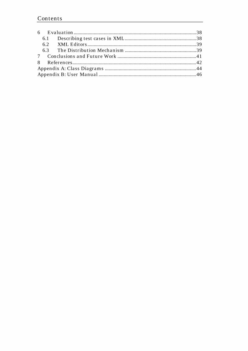
The Internet Protocol based Base Station Subsystem (IP-BSS) is an IP based system able to handle a combination of wireless packet data (GPRS and EDGE) and circuit switched GSM services. An overview of the IP BSS system is shown in figure 2 – 1.
2.1.1 IP-BSS Architecture The IP-BSS architecture comprises the following system components: The IP-BSS architecture comprises the following system components: • Radio Network Server (RNS)
The Radio Network Server handles all radio network functions (for example, handover and channel allocation). The RNS has an open platform architecture and is built on Ericsson’s new server based platform. The network applications are written in Java and the operating system is Solaris. The RNS hardware consists of a high performance, open industry standard multiprocessor platform.
• IP Network The IP network consists of real-time routers that have been specially designed for the real-time environment in a radio access network. The IP transport layer enables the non real-time data traffic to be run with lower priority within the BSS network “on top of” real-time traffic, such as speech. This leads to increased flexibility in the dimensioning and significant transmission savings
Figure 2 - 1: Illustrating the different nodes of the complete IP-BSS system. The separate parts are developed by different units within Ericsson, in parallel. The main focus of this project is the verification of functionality in the Radio network Server (RNS) node.
RBS BSS GW
O&M
RNS
IP Network

Test Environment
10
compared to circuit switched implementations, where bandwidth is peak allocated
• BSS Gateway The BSS Gateway connects the base station subsystem to the core network. It connects the IP and circuit switched networks.
• Radio Base Station (RBS) The Radio Base Station is the link between the wireless and the wired networks.
• Operation and Maintenance System (O&M) Used for configuration and maintenance of the system.
2.1.2 Verification of Functionality The verification team does the testing concerned by this project. The objective is thus to aid them in their work in assuring correct functionality of the product. The verification of functionality is within this scope performed on node level were all components of the system, except the ones that are being tested, are simulated. The test environment is depicted in fig. 2 – 1. The different parts of the system, the nodes, are developed in parallel, which makes it hard to test the whole system before all the nodes are finished. This problem is addressed by simulating all nodes of the system except for the nodes that are currently being tested. All nodes have well defined interfaces of communication, which makes this simulation possible. There are a number of test tools available for simulating traffic in this environment each with its benefits and drawbacks. One common thing for these tools is that they require implementation of advanced test programs to do the simulation. To set up the environment and execute test cases is a time-consuming process and on every new release of the system regression tests have to be performed in order to verify that the old functionality is still correct.
2.2 Documents Related To Testing Amongst the routines for testing Ericsson uses a document structure that describes the expected functionality as well as the test cases that are supposed to be passed. The documents are written in MS Word. To be able to understand the test process an understanding of these documents are important. To be able to automate the test process these documents should be converted to a format that is more suitable for parsing and interpretation by a computer program.
Test Environment
11
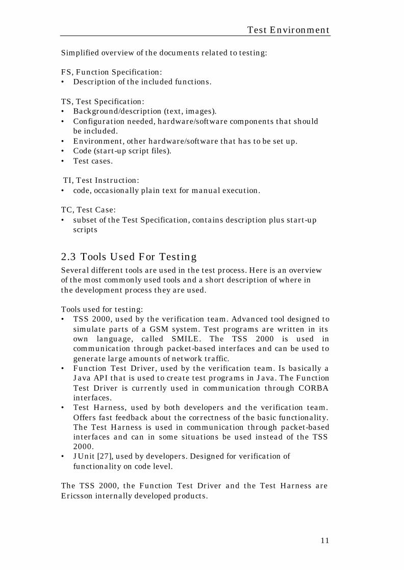
Simplified overview of the documents related to testing: FS, Function Specification: • Description of the included functions. TS, Test Specification: • Background/description (text, images). • Configuration needed, hardware/software components that should
be included. • Environment, other hardware/software that has to be set up. • Code (start-up script files). • Test cases. TI, Test Instruction: • code, occasionally plain text for manual execution. TC, Test Case: • subset of the Test Specification, contains description plus start-up
scripts
2.3 Tools Used For Testing Several different tools are used in the test process. Here is an overview of the most commonly used tools and a short description of where in the development process they are used. Tools used for testing: • TSS 2000, used by the verification team. Advanced tool designed to
simulate parts of a GSM system. Test programs are written in its own language, called SMILE. The TSS 2000 is used in communication through packet-based interfaces and can be used to generate large amounts of network traffic.
• Function Test Driver, used by the verification team. Is basically a Java API that is used to create test programs in Java. The Function Test Driver is currently used in communication through CORBA interfaces.
• Test Harness, used by both developers and the verification team. Offers fast feedback about the correctness of the basic functionality. The Test Harness is used in communication through packet-based interfaces and can in some situations be used instead of the TSS 2000.
• JUnit [27], used by developers. Designed for verification of functionality on code level.
The TSS 2000, the Function Test Driver and the Test Harness are Ericsson internally developed products.
Overview of Technologies
12
3 Overview of Technologies This chapter gives a brief introduction to the different technologies used in this project. An introduction to XML is followed by an introduction to Jini and JavaSpaces.
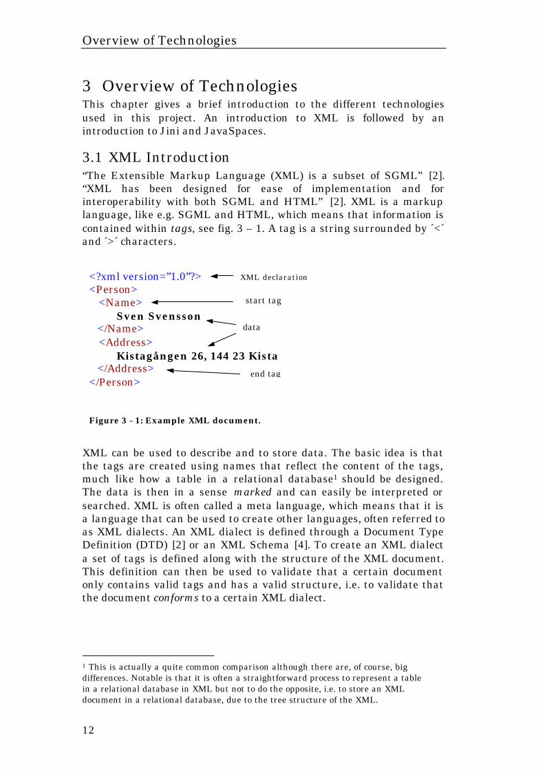
3.1 XML Introduction “The Extensible Markup Language (XML) is a subset of SGML” [2]. “XML has been designed for ease of implementation and for interoperability with both SGML and HTML” [2]. XML is a markup language, like e.g. SGML and HTML, which means that information is contained within tags, see fig. 3 – 1. A tag is a string surrounded by ´<´ and ´>´ characters. XML can be used to describe and to store data. The basic idea is that the tags are created using names that reflect the content of the tags, much like how a table in a relational database1 should be designed. The data is then in a sense marked and can easily be interpreted or searched. XML is often called a meta language, which means that it is a language that can be used to create other languages, often referred to as XML dialects. An XML dialect is defined through a Document Type Definition (DTD) [2] or an XML Schema [4]. To create an XML dialect a set of tags is defined along with the structure of the XML document. This definition can then be used to validate that a certain document only contains valid tags and has a valid structure, i.e. to validate that the document conforms to a certain XML dialect.
1 This is actually a quite common comparison although there are, of course, big differences. Notable is that it is often a straightforward process to represent a table in a relational database in XML but not to do the opposite, i.e. to store an XML document in a relational database, due to the tree structure of the XML.
<?xml version=”1.0”?> <Person> <Name>
Sven Svensson </Name> <Address> Kistagången 26, 144 23 Kista </Address> </Person>
XML declaration
start tag
data
Figure 3 - 1: Example XML document.
end tag
Overview of Technologies
13
To create an XML document, as described above, is a very simple task2 and this is part of what makes it so useful and popular. What makes XML really powerful are the possibility to automatically validate documents, the possibility to process XML in computer programs in a standardized way as well as the possibility to convert XML documents into e.g. HTML or PDF by applying a style sheet that is independent of the data contained in the document.
3.1.1 Validating XML Validating XML means ensuring that a document conforms to a given standard, or dialect. This means that the structure of a specific type of XML documents should be specified beforehand. Every document that conforms to this specification, XML Schema or Document Type Definition3 (DTD), is a valid XML document of that type.
3.1.2 Parsing XML XML documents can be parsed by computer programs. To parse a document means that a program traverses the document and takes different actions that reflect the content of the document. Programs that can be used to parse XML documents are generally referred to as XML parsers. There are several APIs available for parsing and processing XML documents. This gives a system the ability to parse XML documents, manipulate the content (e.g. add or remove data) and then write the data back to a new XML document. There are XML parsers available, for free, for virtually every well-known programming language.
3.1.3 Converting XML The Extensible Style sheet Language (XSL) [9] is an XML based language that can be used to convert an XML document into a document of another type. Conversions between two dialects of XML, from XML to HTML or XML to PDF are some of the applications of XSL. Some web browsers have built in support for XML to HTML conversions, for example Internet Explorer 5 and Mozilla. XML can easily be converted to HTML by applying an XSL style sheet. In this way the data is contained in the XML file and the style, i.e. the layout, is described in the XSL file. This means that the content of a web page can be altered or exchanged without changing the appearance of the page and vice versa. XML thus provides a separation
2 I.e. technically speaking, it does require a lot of work to make an elegant and functional design when dealing with complicated issues. 3 See chapter 3.5 for more information about XML Schemas and DTDs.
Overview of Technologies
14
of data and layout, which greatly simplifies the maintenance of a web page with content that frequently changes.
3.2 SAX, DOM and JDOM In order to be able to read and manipulate XML documents programmatically an Application Programming Interface (API) is needed. The most well known are the Document Object Model (DOM) [7], the Simple API for XML (SAX) [6] and JDOM [18]. The document object model is a W3C [20] standard and provides an in-memory tree representation of XML documents. That is, the nodes of the XML documents are represented as objects arranged in a tree structure. The tree can be edited dynamically; nodes can be added or removed and the modified tree can then be stored as a new XML document. The DOM API can also be used to create an XML document from scratch based on input from any desired source of information. The simple API for XML is not a W3C standard but has due to its enormous popularity reached the status of a standard. SAX does not build an in-memory structure representing an XML document, as the DOM does, instead it sends events to registered listeners as the document is traversed. It is then up to the program that receives these events to react on them in whatever suitable way. The simple API for XML is thus a more lightweight API that can be used whenever an in-memory representation of a document is not needed. JDOM is a new open source Java API for reading, writing and manipulating XML from Java programs. JDOM has similarities with the document object model (DOM), the document is represented as a tree structure built up of Java objects. JDOM is designed from the start to be implemented in Java and therefore offers more advanced capabilities than the general DOM. For example extracting nodes from the JDOM tree is simpler than from the DOM tree. Furthermore it is easier to use JDOM to create XML documents from scratch, building their structure dynamically, than DOM. JDOM is not a standard but a JDOM representation can easily be converted into a DOM repres-entation if required.
3.3 Choosing XML Parser There are a vast number of Java XML parsers, most of which are free of charge. Most XML parsers come bundled with a set of utility classes, an API, that simplifies XML processing. The parsers and the corresponding APIs can be combined in any way so that, e.g., the fastest parser can be combined with an API that suits a specific need. The most well known parsers written in Java are:
Overview of Technologies
15
• The Java Project X Parser, developed by SUN but donated to the Apache Xerces Project. Supports XML 1.0. No XML Schema support. Requires jdk1.1 or later.
• The XML4J Parser, developed by IBM but donated to the Apache Xerces Project. Has a lot of nice features, such as a DTD class. Requires jdk1.1 or later.
• The Xerces-J Parser, is devloped as an open source project by The Apache Group. Both XML4J and JAXP (the java project x parser) will be integrated in Xerces-J why it will be the most complete parser. Supports part of the XML Schema draft and allows parsing of DTDs. Requires jdk1.1 or later.
• JDOM, JDOM is not a parser, it actually uses the Xerces-J parser, it is a Java API developed as an open source project. JDOM is designed and written exclusively for Java and makes use of the reflection and collection APIs why it is the most easy to use XML API for Java. Requires jdk1.2 or jdk1.1 with the Collections extension.
3.4 XML on the Network A popular application of XML is as an information container for communication between different systems that exchange data. Here XML is very popular because of the easy way to specify and verify that data conform to the various interfaces of the applications. There is a downside, however, a message-based protocol with messages described in XML introduces a lot of overhead since the tags and attributes themselves constitute a large fraction of XML documents.
3.5 XML Schemas and DTDs A DTD provides applications with advance notice of what names and structures can be used in a particular document type. Using a DTD means you can be certain that all documents belonging to a particular type will be constructed and named in a conformant manner. However, DTDs are very limited. For example it is not possible to restrict the range of a numeric field, just to specify the type of the field. Also, DTDs are written with its own special syntax. An alternative to DTDs are XML Schemas which is a much more powerful way to define the structure of a document. XML Schema is a relatively new concept though, the specification is not finalised yet. Since the specification is not finalised the standard validating parsers do not yet support XML Schemas.
Overview of Technologies
16
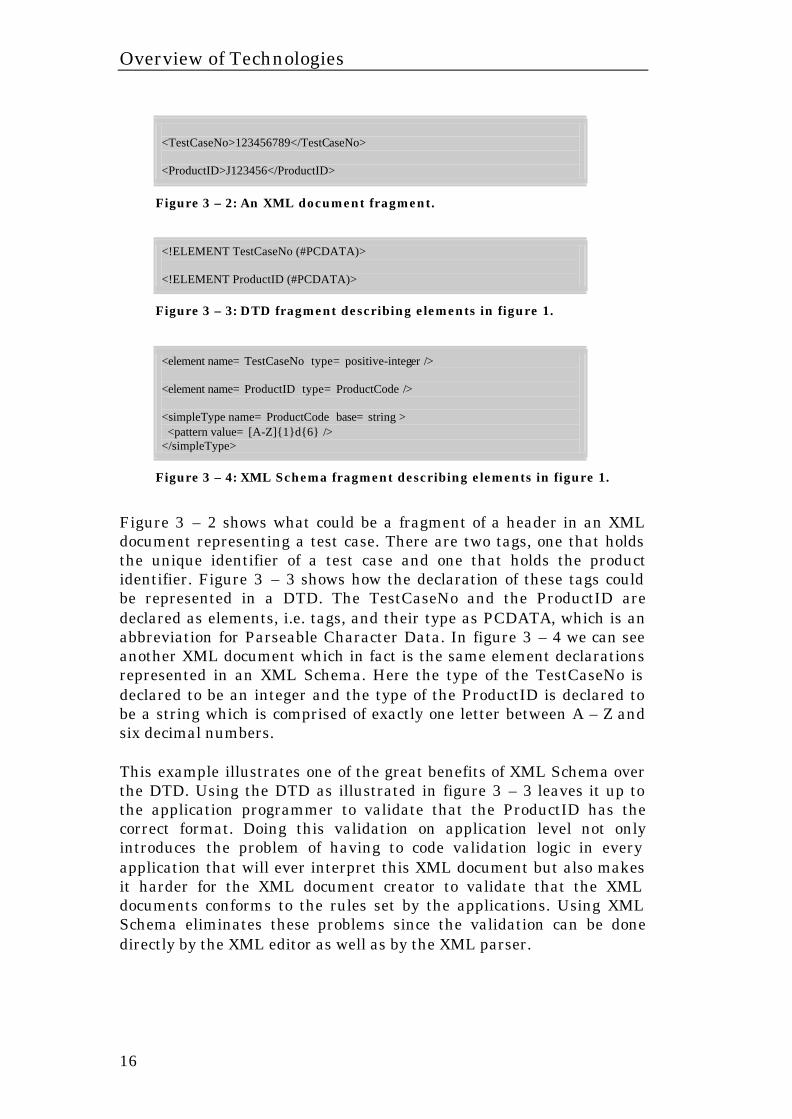
<TestCaseNo>123456789</TestCaseNo> <ProductID>J123456</ProductID>
Figure 3 – 2: An XML document fragment.
<!ELEMENT TestCaseNo (#PCDATA)> <!ELEMENT ProductID (#PCDATA)>
Figure 3 – 3: DTD fragment describing elements in figure 1.
<element name= TestCaseNo type= positive-integer /> <element name= ProductID type= ProductCode /> <simpleType name= ProductCode base= string > <pattern value= [A-Z]{1}d{6} /> </simpleType>
Figure 3 – 4: XML Schema fragment describing elements in figure 1.
Figure 3 – 2 shows what could be a fragment of a header in an XML document representing a test case. There are two tags, one that holds the unique identifier of a test case and one that holds the product identifier. Figure 3 – 3 shows how the declaration of these tags could be represented in a DTD. The TestCaseNo and the ProductID are declared as elements, i.e. tags, and their type as PCDATA, which is an abbreviation for Parseable Character Data. In figure 3 – 4 we can see another XML document which in fact is the same element declarations represented in an XML Schema. Here the type of the TestCaseNo is declared to be an integer and the type of the ProductID is declared to be a string which is comprised of exactly one letter between A – Z and six decimal numbers. This example illustrates one of the great benefits of XML Schema over the DTD. Using the DTD as illustrated in figure 3 – 3 leaves it up to the application programmer to validate that the ProductID has the correct format. Doing this validation on application level not only introduces the problem of having to code validation logic in every application that will ever interpret this XML document but also makes it harder for the XML document creator to validate that the XML documents conforms to the rules set by the applications. Using XML Schema eliminates these problems since the validation can be done directly by the XML editor as well as by the XML parser.
Overview of Technologies
17
XML Schemas are written in XML and this is an advantage compared to DTDs. This means that the definition of an XML document can be parsed and interpreted by a program using the same tools as for the document itself.
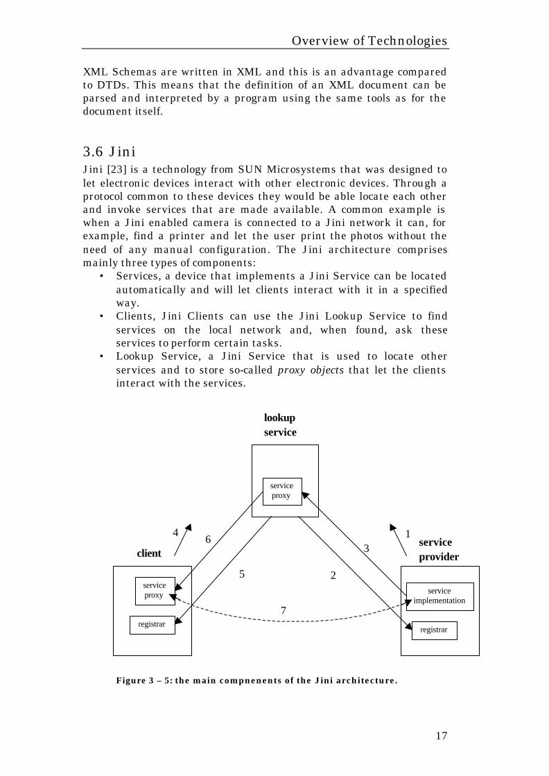
3.6 Jini Jini [23] is a technology from SUN Microsystems that was designed to let electronic devices interact with other electronic devices. Through a protocol common to these devices they would be able locate each other and invoke services that are made available. A common example is when a Jini enabled camera is connected to a Jini network it can, for example, find a printer and let the user print the photos without the need of any manual configuration. The Jini architecture comprises mainly three types of components:
• Services, a device that implements a Jini Service can be located automatically and will let clients interact with it in a specified way.
• Clients, Jini Clients can use the Jini Lookup Service to find services on the local network and, when found, ask these services to perform certain tasks.
• Lookup Service, a Jini Service that is used to locate other services and to store so-called proxy objects that let the clients interact with the services.
Figure 3 – 5: the main compnenents of the Jini architecture.
lookup service
service provider client
service proxy
registrar
service implementation
registrar
service proxy
3
2 5
6
7
1 4
Overview of Technologies
18
The Lookup Service lets clients find the available services. Figure 3 – 5 shows the flow of events when a service is registered with the lookup service and a client finds this service and calls it.
1. The service provider sends a multicast message on the network. 2. The lookup service answers by returning a registrar object that
the service provider can use for further, direct, communication with the lookup service.
3. The service provider uploads a service proxy to the lookup service. The service proxy can be anything in between a proxy object that forwards all method calls, performed by the client, to the service implementation on the service provider to a full implementation of the service that is executed solely on the client side.
4. The client sends a multicast message on the network. 5. The lookup service answers by returning a registrar object that
the client can use for further, direct, communication with the lookup service.
6. The client asks for a certain service and the lookup service returns the service proxy object.
7. The client starts using the service and depending on the implementation of the service proxy the proxy might do remote calls to the service object on the service provider.
Following are two especially interesting features of the Jini architecture that should be stressed.
• Neither the client nor the service provider need to know the location (i.e. IP-address or hostname) of neither each other nor the lookup service. The dynamic lookup service makes it possible to extend the system with both new services and new clients without having to alter any system properties, such as configurations.
• The implementation details of a service are not known by the client. Instead the client communicates with the service proxy through a well-known interface. If communication between the service proxy and the service implementation is necessary the service proxy will handle all the details transparently.
Overview of Technologies
19
3.7 JavaSpaces The JavaSpaces [24] service is a distributed object storage strongly influenced by the Linda4 systems. SUN Microsystems provides the specification and has a publicly available implementation of the specification, called outrigger. The JavaSpaces service fits into the Jini architecture by being a Jini service. By combining Jini and JavaSpaces the JavaSpaces service’s user can use the Jini lookup service to locate the JavaSpace. This reduces the amount of configuration that has to be performed in order to get the system up and running. The JavaSpaces service can be seen as a distributed object database in which objects can be stored and retrieved from. There are major differences, though, for example a simple matching mechanism is used to retrieve objects from the JavaSpace as opposed to the querying performed at databases. An object that can be stored in a JavaSpaces service is called an Entry and implements the “Entry interface”. When an entry is stored in the JavaSpace it can be retrieved by sending a request to the space including a template object. The JavaSpace performs a matching operation on the entries contained in the space, using the template, and if the matching is successful the entry that matched the template is returned. The JavaSpaces service can be seen as a tool for writing distributed algorithms, it provides mechanisms for synchronisation of threads and transactions.
4 “Linda” is the name of a public domain technology originally propounded by Dr. David Gelernter of Yale University [26].
Overview of Technologies
20
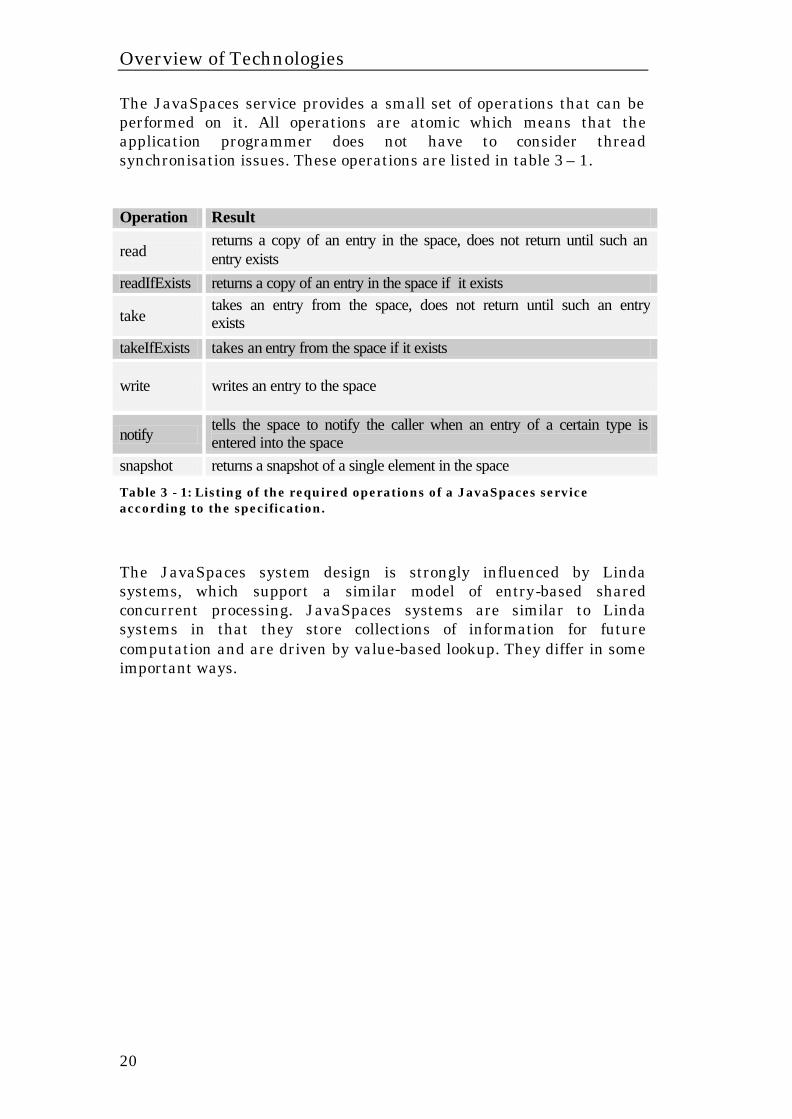
The JavaSpaces service provides a small set of operations that can be performed on it. All operations are atomic which means that the application programmer does not have to consider thread synchronisation issues. These operations are listed in table 3 – 1. Operation Result
read returns a copy of an entry in the space, does not return until such an entry exists
readIfExists returns a copy of an entry in the space if it exists
take takes an entry from the space, does not return until such an entry exists
takeIfExists takes an entry from the space if it exists
write writes an entry to the space
notify tells the space to notify the caller when an entry of a certain type is entered into the space
snapshot returns a snapshot of a single element in the space
Table 3 - 1: Listing of the required operations of a JavaSpaces service according to the specification.
The JavaSpaces system design is strongly influenced by Linda systems, which support a similar model of entry-based shared concurrent processing. JavaSpaces systems are similar to Linda systems in that they store collections of information for future computation and are driven by value-based lookup. They differ in some important ways.
Integration And Verification Test Model (IVTM)
21
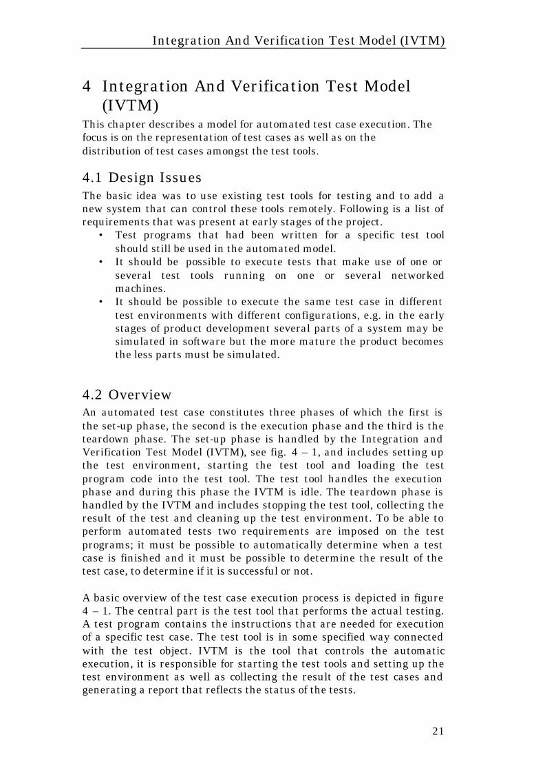
4 Integration And Verification Test Model (IVTM)
This chapter describes a model for automated test case execution. The focus is on the representation of test cases as well as on the distribution of test cases amongst the test tools.
4.1 Design Issues The basic idea was to use existing test tools for testing and to add a new system that can control these tools remotely. Following is a list of requirements that was present at early stages of the project.
• Test programs that had been written for a specific test tool should still be used in the automated model.
• It should be possible to execute tests that make use of one or several test tools running on one or several networked machines.
• It should be possible to execute the same test case in different test environments with different configurations, e.g. in the early stages of product development several parts of a system may be simulated in software but the more mature the product becomes the less parts must be simulated.
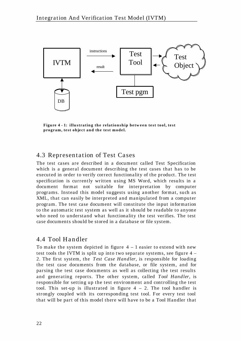
4.2 Overview An automated test case constitutes three phases of which the first is the set-up phase, the second is the execution phase and the third is the teardown phase. The set-up phase is handled by the Integration and Verification Test Model (IVTM), see fig. 4 – 1, and includes setting up the test environment, starting the test tool and loading the test program code into the test tool. The test tool handles the execution phase and during this phase the IVTM is idle. The teardown phase is handled by the IVTM and includes stopping the test tool, collecting the result of the test and cleaning up the test environment. To be able to perform automated tests two requirements are imposed on the test programs; it must be possible to automatically determine when a test case is finished and it must be possible to determine the result of the test case, to determine if it is successful or not. A basic overview of the test case execution process is depicted in figure 4 – 1. The central part is the test tool that performs the actual testing. A test program contains the instructions that are needed for execution of a specific test case. The test tool is in some specified way connected with the test object. IVTM is the tool that controls the automatic execution, it is responsible for starting the test tools and setting up the test environment as well as collecting the result of the test cases and generating a report that reflects the status of the tests.
Integration And Verification Test Model (IVTM)
22
Figure 4 - 1: illustrating the relationship between test tool, test program, test object and the test model.
4.3 Representation of Test Cases The test cases are described in a document called Test Specification which is a general document describing the test cases that has to be executed in order to verify correct functionality of the product. The test specification is currently written using MS Word, which results in a document format not suitable for interpretation by computer programs. Instead this model suggests using another format, such as XML, that can easily be interpreted and manipulated from a computer program. The test case document will constitute the input information to the automatic test system as well as it should be readable to anyone who need to understand what functionality the test verifies. The test case documents should be stored in a database or file system.
4.4 Tool Handler To make the system depicted in figure 4 – 1 easier to extend with new test tools the IVTM is split up into two separate systems, see figure 4 –2. The first system, the Test Case Handler, is responsible for loading the test case documents from the database, or file system, and for parsing the test case documents as well as collecting the test results and generating reports. The other system, called Tool Handler, is responsible for setting up the test environment and controlling the test tool. This set-up is illustrated in figure 4 – 2. The tool handler is strongly coupled with its corresponding test tool. For every test tool that will be part of this model there will have to be a Tool Handler that
Test pgm
IVTM
instructions
result
Test Object
Test Tool
DB

Integration And Verification Test Model (IVTM)
23
can control the test tool. This, in turn, requires that the test tool can be remotely controlled by another system. The Tool Handler may have the responsibility to set up the test object prior to executing a test case. This means that before a test case can be executed the Tool Handler sets up both the test object and the test tool used. The test object may have more than one interface for communication, e.g. one CORBA interface and one interface that communicates through a simple UDP based protocol. This introduces the need of using several different test tools, connected to the same test object, and participating in the same test case. This is also illustrated in figure 4 – 2 where two test tools are connected to the same test object. The test tool, or tools, can be running on either the same machine as the test object or on dedicated machines depending on the type of test case. Every Tool Handler must have a well-defined interface for communication. The Test Case Handler communicates with the Tool Handlers through a message-based protocol where the messages contain test instructions or results from the test case executions.
Tool Handler
Figure 4 - 2: illustrating the role of the tool handlers in the system model. The test case handler is connected to a database or file system where test case documents and reports are stored
IVTM Tool
Handler
Tool Handler
Test Case
Handler
Test pgm
instructions
result
Test Tool
Test pgm
instructions
result
Test Tool
Test
Object
DB
. . .
Integration And Verification Test Model (IVTM)
24
4.5 Distributing Test Cases A test case may involve one or several test tools running on one or several networked machines connected to the test object. Therefore, it must be possible to execute test cases that involve several test tools running on different machines on the network. To achieve this some kind of mechanism for distribution of test cases had to be added to the model. The solution became to let the Test Case Handler partition the representation of a test case into one or several tasks. Every task would then contain all the information needed to execute the part of the test case that is aimed for one single test tool. The task could then be assigned to a Tool Handler. The communication between Test Case Handler and Tool Handlers can be performed using any mechanism that allows message passing between systems running on different machines. Examples of such mechanisms are CORBA and Java’s RMI. From a performance point of view the choice of communication mechanism is not important since the actual test case execution will dominate in the total execution time of the system. The protocol for communication between the Test Case Handler and Tool Handlers will be a simple form of a send-expect protocol, i.e. a protocol that lets the communicating parties send a message and then wait for the, previously specified, expected answer. In the communication model of Test Case Handler to Tool Handler the Test Case Handler sends a task message to a Tool Handler and then expects a result message in return. The task message contains the information extracted from the test case document and the result message can contain anything from a comma-separated list of strings to an XML document.
4.6 Extending the Model With A New Test Tool The test environment is constantly changing to reflect the progress of the work on the product. To make the process of incorporating a new test tool into this model as simple as possible the mechanisms for interaction with test tools has to be as general as possible. It was decided that when a new test tool is introduced its corresponding Tool Handler should announce itself on the network. This announcement should include an interface description as well as the location, e.g. hostname, of the machine it is currently running on. By letting the Tool Handlers announce themselves as described introduces some very interesting possibilities. Firstly, there is no need to inform the Test Case Handler about the location and interfaces of the Tool Handlers, all necessary information will be passed on to a suitable Tool Handler based on some criteria specified in the test case document. Secondly, the introduction of a new test tool does not require any extra
Integration And Verification Test Model (IVTM)
25
configuration or a restart of the system. Thirdly, if some of the system components, e.g. tool handler or test tool, goes down due to some failure the rest of the system will be left intact and the test case handler may find another test tool that can execute that test case.
4.7 Requirements on Test Tools There are some requirements that have to be met in order to make this model successful. Following are requirements, imposed by this model, on the test tools:
• It must be possible to remote control the test tools. • The test programs must be designed to let the Test Case
Handler know when the test case is finished. • The test programs must be designed to let the Test Case
Handler know if the test case is successful or not.

Implementation
26
5 Implementation The previous chapter described a model for automatic test case execution. This chapter will take on were that chapter ended and explain how this model was implemented and motivate the design choices made. The two major parts discussed in the previous chapter were how the test cases should be represented and how the distribution of test cases amongst the test tools should be handled. This chapter describes the components of the system and motivates the design choices made.
5.1 System Overview It was early in the project decided that XML would be used for representation of test cases. XML is a widely spread standard with numerous application programming interfaces and parsers available. XML is both suitable from an application programming point of view as well as it offers the features of validation that is necessary from the test case creator’s, i.e. the user’s, point of view. Also, the test cases can be converted into other formats, using XSL (see chapter 3.1.3), to be readable to anyone not familiar with XML. XML is also used in the communication between the different parts of the system. The Tool Handlers must have a well-defined interface for communication. This interface is described using a DTD or XML Schema, although the current implementation only supports DTDs. The Test Case Handler communicates with the Tool Handlers through a message-based protocol where the messages contain the partitioned XML representations of test cases, i.e. tasks, or results from tests. The mechanism for distribution of test cases, or tasks, was chosen to be the Jini service JavaSpaces. The JavaSpaces service was chosen to handle the communication between the Test Case Handler and the Tool Handlers. Every message, e.g. tasks or results, are placed in the JavaSpaces service and picked up by the recipients. This solution makes it possible for the Test Case Handler to communicate with the Tool Handlers without knowing their location within the network. Using the JavaSpaces service to distribute the test cases also makes it possible to do automated testing using an arbitrary number of test tools executing simultaneously. The Test Case Handler can in fact be seen as a compute server, which distributes tasks among its clients, or servants. Each Tool Handler picks up tasks at its own pace, determined by the speed of the computer it runs on as well as the size of the task. The number of running Tool Handlers can be altered during execution in order to better adapt to the number of pending tasks. When there are only a
Implementation
27
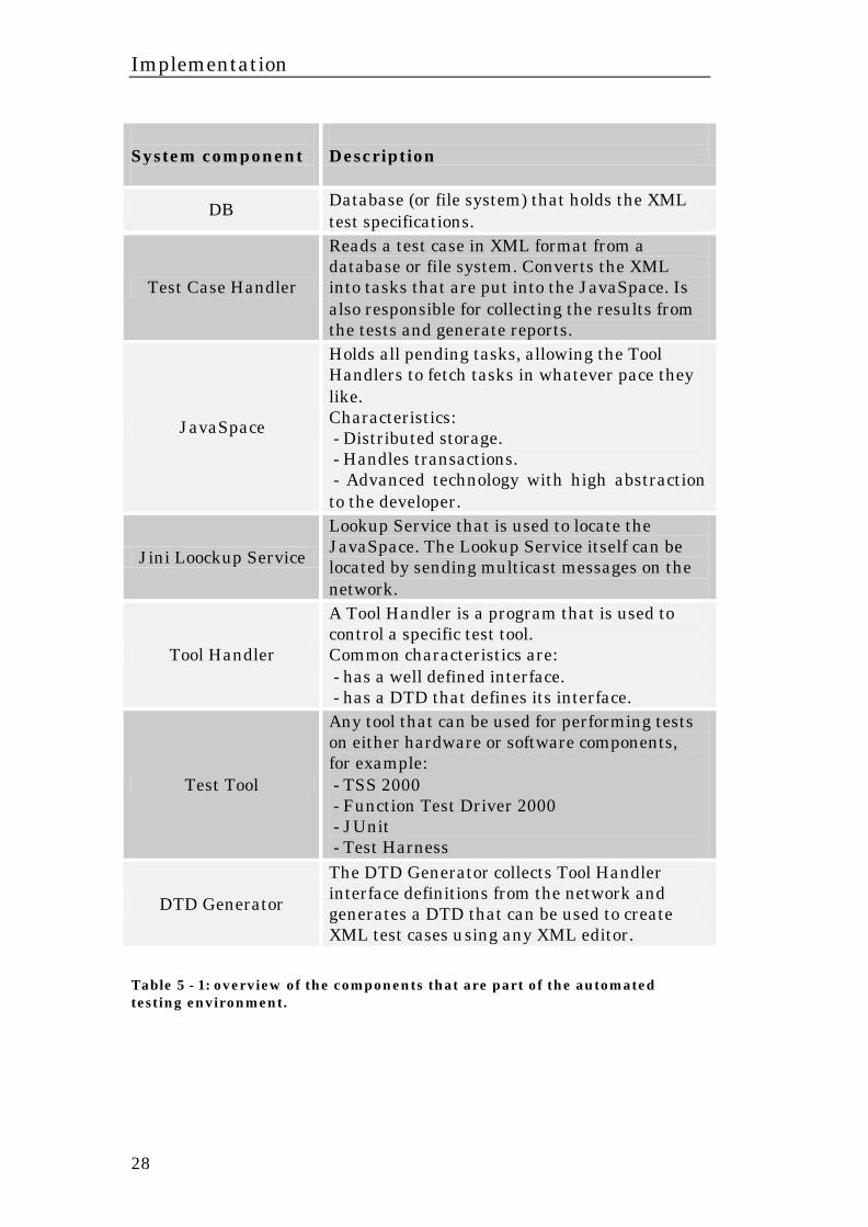
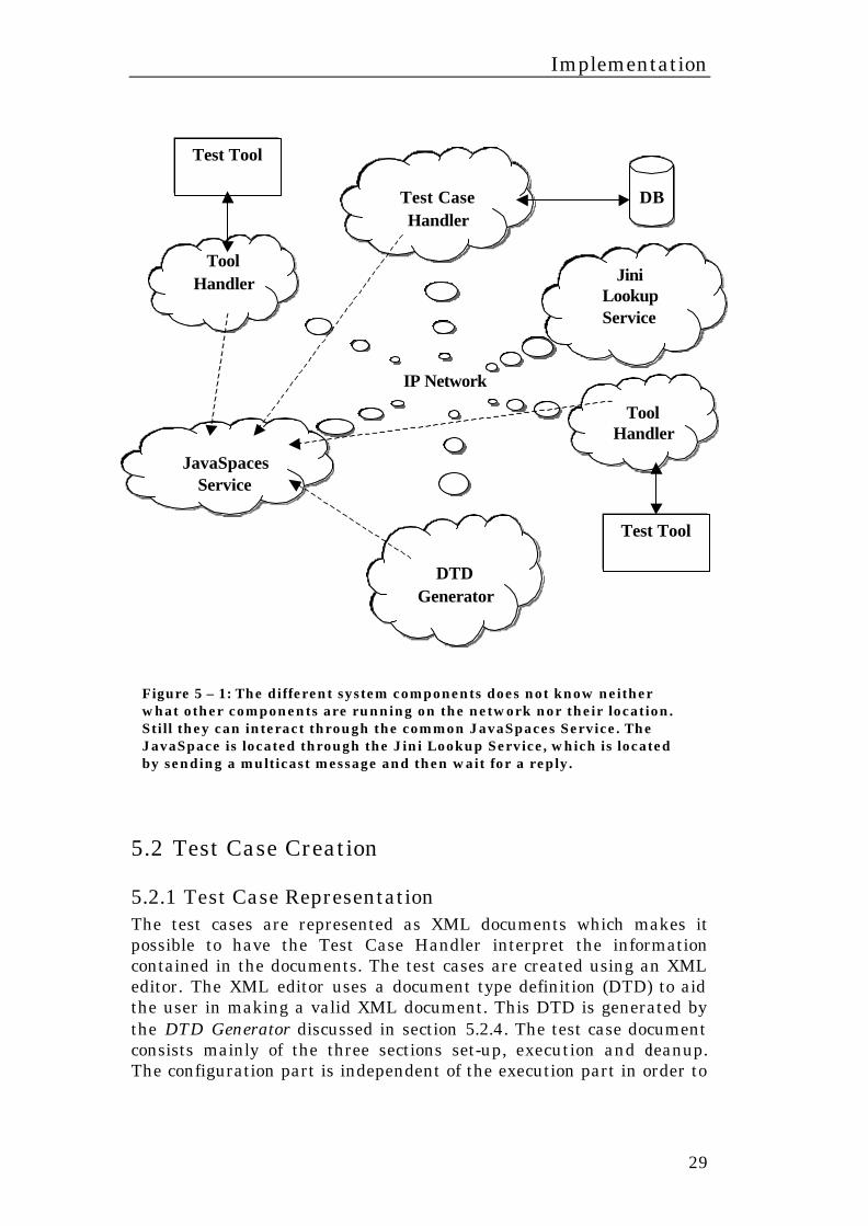
few pending tasks it may be considered enough to have just one running test tool and when there are a lot any number of test tools can be started. Using the Jini lookup service to locate the available JavaSpaces services on the network brings the possibility to automatically detect what test tools are available at a given time. Also, the system could be extended with new test tools dynamically since no part of the system is dependent of another part. The process of testing can be viewed as two isolated processes of which the first is the test case creation process and the second the test case execution process. Each of these two processes is described in more detail in the next two sections. See table 5 – 1 and figure 5 – 1 for an overview of the components discussed in the next two sections.
Implementation
28
System component
Description
DB Database (or file system) that holds the XML test specifications.
Test Case Handler
Reads a test case in XML format from a database or file system. Converts the XML into tasks that are put into the JavaSpace. Is also responsible for collecting the results from the tests and generate reports.
JavaSpace
Holds all pending tasks, allowing the Tool Handlers to fetch tasks in whatever pace they like. Characteristics: - Distributed storage. - Handles transactions. - Advanced technology with high abstraction to the developer.
Jini Loockup Service
Lookup Service that is used to locate the JavaSpace. The Lookup Service itself can be located by sending multicast messages on the network.
Tool Handler
A Tool Handler is a program that is used to control a specific test tool. Common characteristics are: - has a well defined interface. - has a DTD that defines its interface.
Test Tool
Any tool that can be used for performing tests on either hardware or software components, for example: - TSS 2000 - Function Test Driver 2000 - JUnit - Test Harness
DTD Generator
The DTD Generator collects Tool Handler interface definitions from the network and generates a DTD that can be used to create XML test cases using any XML editor.
Table 5 - 1: overview of the components that are part of the automated testing environment.
Implementation
29
5.2 Test Case Creation
5.2.1 Test Case Representation The test cases are represented as XML documents which makes it possible to have the Test Case Handler interpret the information contained in the documents. The test cases are created using an XML editor. The XML editor uses a document type definition (DTD) to aid the user in making a valid XML document. This DTD is generated by the DTD Generator discussed in section 5.2.4. The test case document consists mainly of the three sections set-up, execution and cleanup. The configuration part is independent of the execution part in order to
Test Case Handler
JavaSpaces Service
DTD Generator
Jini Lookup Service
Tool Handler
Test Tool
IP Network
DB
Tool Handler
Test Tool
Figure 5 – 1: The different system components does not know neither what other components are running on the network nor their location. Still they can interact through the common JavaSpaces Service. The JavaSpace is located through the Jini Lookup Service, which is located by sending a multicast message and then wait for a reply.
Implementation
30
make it possible to execute the same test case in different environments with different configurations. The XML representation of a test case constitutes the input information to the automatic test system.
5.2.2 Generating XML Coding XML in a text editor is something you generally want to avoid. There are mainly two reasons for this. Firstly, to make a document that conforms to a specific DTD or XML Schema can be tricky if you are not used to XML coding. Secondly, the readability of an XML document is not very high since a relatively large portion of the document consists of tags and attributes. Instead you want to use an XML editor or generate the XML document automatically from some other document type. An XML editor is an editor that can be of big help when creating XML documents. There are a large number of XML editors, e.g. XMetaL [23], on the market, enough for everyone to find an editor that suites their needs. There are XML editors that are free, developed as open source projects, as well as more expensive ones with support for SGML. A lot of these editors are based on the same concept, an expandable tree in which all nodes can be overviewed and edited as well as a dedicated area for text input. Usually there is also the possibility to validate a document against the DTD, browse the generated XML and sometimes to design and apply style sheets.
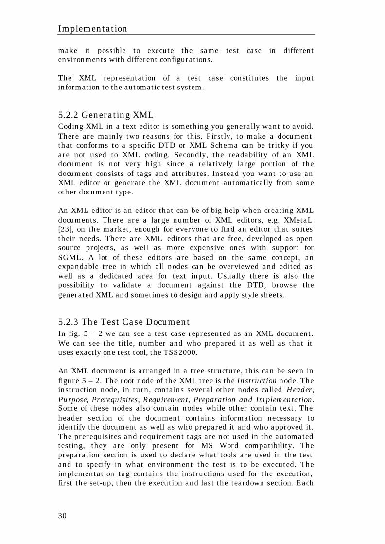
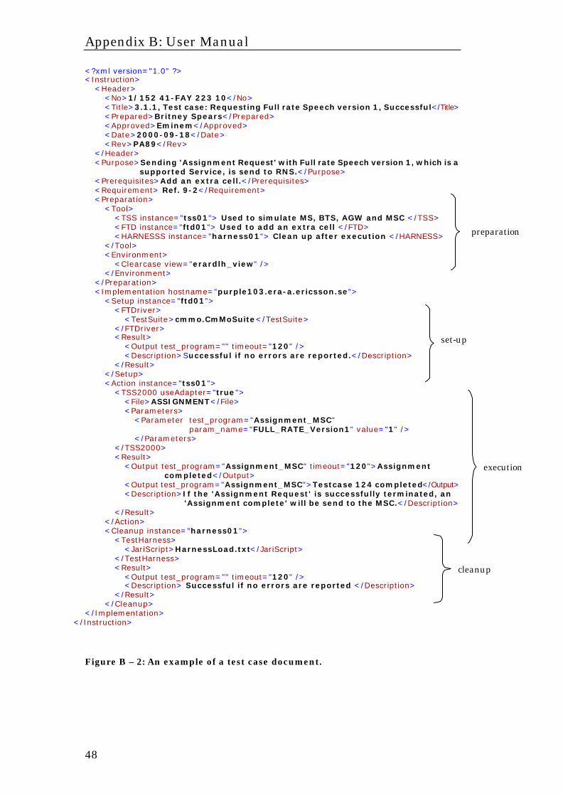
5.2.3 The Test Case Document In fig. 5 – 2 we can see a test case represented as an XML document. We can see the title, number and who prepared it as well as that it uses exactly one test tool, the TSS2000. An XML document is arranged in a tree structure, this can be seen in figure 5 – 2. The root node of the XML tree is the Instruction node. The instruction node, in turn, contains several other nodes called Header, Purpose, Prerequisites, Requirement, Preparation and Implementation. Some of these nodes also contain nodes while other contain text. The header section of the document contains information necessary to identify the document as well as who prepared it and who approved it. The prerequisites and requirement tags are not used in the automated testing, they are only present for MS Word compatibility. The preparation section is used to declare what tools are used in the test and to specify in what environment the test is to be executed. The implementation tag contains the instructions used for the execution, first the set-up, then the execution and last the teardown section. Each
Implementation
31
of the set-up, action and teardown tags contain one or several instructions and then a result tag. The test case document is partitioned into one or several tasks that are assigned to one or several Tool Handlers. The document illustrated in figure 5 – 2 is partitioned into three tasks, with a mutual restriction regarding in what order they may be executed. The three tasks correspond to the sections set-up, action and cleanup. The instructions contained in the three sections is depending on what Tool Handler they are to be sent to, i.e. the XML used in these sections is defined in the corresponding Tool Handler interface definition. This means that the instructions used in the test case document depend on the Tool Handler implementation.
Implementation
32
<?xml version="1.0" ?> <Instruction> <Header> <No>1/152 41-FAY 223 10</No> <Title>3.1.1, Test case: Requesting Full rate Speech version 1, Successful</Title> <Prepared>Britney Spears</Prepared> <Approved>Eminem</Approved> <Date>2000-09-18</Date> <Rev>PA89</Rev> </Header> <Purpose>Sending 'Assignment Request' with Full rate Speech version 1, which is a supported Service, is send to RNS.</Purpose> <Prerequisites>Add an extra cell.</Prerequisites> <Requirement> Ref. 9-2</Requirement> <Preparation> <Tool> <TSS instance="tss01">Used to simulate MS, BTS, AGW and MSC.</TSS> <FTD instance="ftd01">Used to add an extra cell.</FTD> </Tool> <Environment> <Clearcase view="erardlh_view" /> </Environment> </Preparation> <Implementation hostname="purple103.era-a.ericsson.se"> <Setup instance="ftd01"> <FTDriver> <TestSuite>cmmo.CmMoSuite</TestSuite> </FTDriver> <Result> <Output test_program="" timeout="120" /> <Description>Successful if no errors are reported.</Description> </Result> </Setup> <Action instance="tss01"> <TSS2000 useAdapter="true"> <File>ASSIGNMENT</File> <Parameters> <Parameter test_program="Assignment_MSC" param_name="FULL_RATE_Version1" value="1" /> </Parameters> </TSS2000> <Result> <Output test_program="Assignment_MSC" timeout="120">Assignment completed</Output> <Output test_program="Assignment_MSC">Testcase 124 completed</Output> <Description>If the 'Assignment Request' is successfully terminated, an 'Assignment complete' will be send to the MSC.</Description> </Result> </Action> <Cleanup instance="ftd01"> <FTDriver> <TestSuite>cmmo.CmMoSuite</TestSuite> </FTDriver> <Result> <Output test_program="" timeout="120" /> <Description> Successful if no errors are reported </Description> </Result> </Cleanup> </Implementation>
</Instruction>
Figure 5 - 2: An XML document representing a simple test case.
set-up
execution
preparation
teardown
Implementation
33
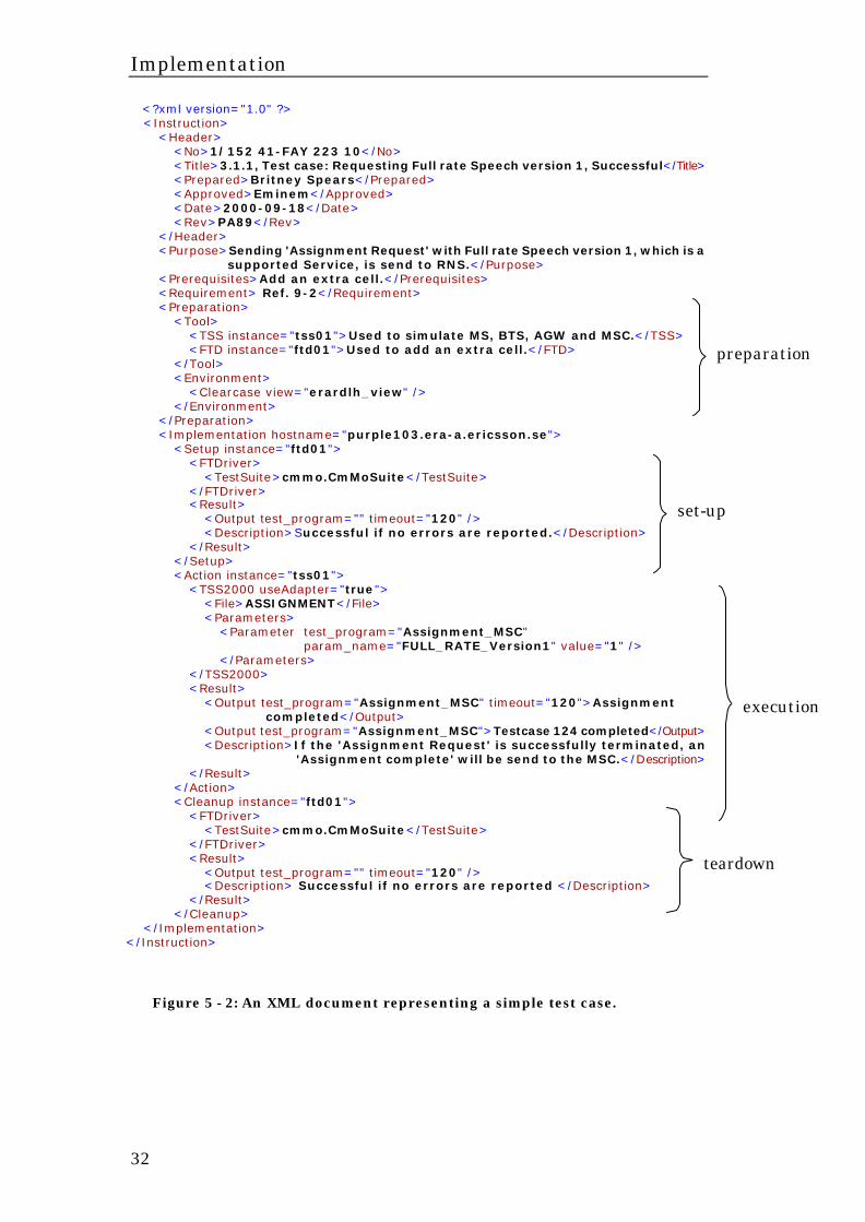
5.2.4 The Report Document The Tool Handlers reports the outcome of a test case by sending a report message to the Test Case Handler. The Test Case Handler collects all these report messages and creates a complete report that contains the results of all test cases. An example of such a report is shown in figure 5 – 3. The report contains a header with information relevant for all test cases as well as test records that reflects the outcome of individual test cases. This report is represented in XML and can be transformed into other formats, such as HTML or PDF. The Test Case Handler by default creates reports in XML, HTML and PDF. <?xml version="1.0" encoding="UTF-8" ?> <Report> <Header> <No>3/385 45-GHJ 345 77</No> <Title>Testsuite ASSIGNMENT</Title> <Prepared>Britney Spears</Prepared> <Approved>Eminem</Approved> <Date>2000-09-18</Date> <Rev>PA89</Rev> <TestDate>Fri Nov 10 12:59:16 CET 2000</TestDate> </Header> <TestRecords> <TestRecord> <Title>3.1.1, Test case: Requesting Full rate Speech version 1, Successful</Title> <Status>OK</Status> <Reason> <Row>Assignment Completed</Row> <Row>Testcase 124 completed</Row> </Reason> </TestRecord> <TestRecord> <Title>3.1.2, Error case: MS reverted to old channel</Title> <Status>NOK</Status> <Reason> <Row>Timer Expired</Row> </Reason> </TestRecord> </TestRecords> </Report>
Figure 5 - 3: Example of the report XML document created by the Test Case Handler after a test case execution is finished.
5.2.5 The DTD Generator To aid the user in the process of creating valid XML representations of test cases a DTD is used as input to the XML editor. The DTD needs to be updated every time a new test tool with a new Tool Handler is introduced since the new Tool Handler may have its own set of instructions. This set of instructions is represented as a DTD and called interface definition. Every tool handler has an interface declaration represented as a DTD document. The DTD Generator collects all interface definitions of all Tool Handlers and puts them together with a general DTD into one “master” DTD. The user then uses this “master” DTD when creating test cases using an XML editor.
Implementation
34
This makes it possible to extend the test environment with new test tools without affecting the rest of the system. No configuration changes are necessary and no currently running test tool or Tool Handler has to be restarted. The main motivation for using this method with a separate interface definition for each Tool Handler is that it eliminates the need to specify a “general” instruction set that is suitable for every possible Tool Handler Implementation. Instead every Tool Handler can use its own custom instruction set, which simplifies the development of new Tool Handlers.
5.2.6 Future Improvements Instead of using DTDs XML Schemas should be used. Using XML Schemas would make the DTD Generator more flexible and extendable. Problem is there are currently no XML editors supporting XML Schema. Instead of using an XML editor to write test cases a new application should be developed. This new application should take an XML Schema and from it generate a graphical user interface that can aid the user in creating valid test cases in a higher degree than is possible with an ordinary XML editor. The application should adapt to the schema and present the user a graphical user interface that is reflecting the XML Schema. Problem is there has not been enough time to implement this yet.
Implementation
35
5.3 Execution of Test Cases
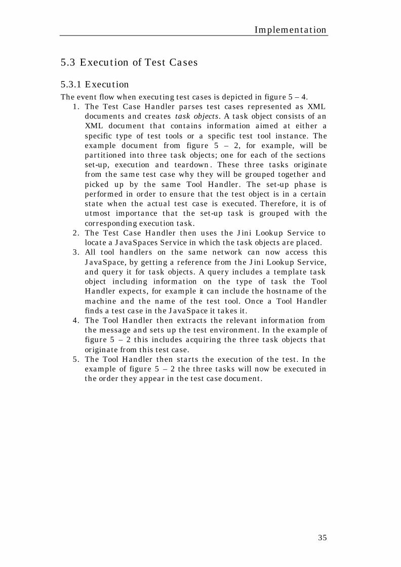
5.3.1 Execution The event flow when executing test cases is depicted in figure 5 – 4.
1. The Test Case Handler parses test cases represented as XML documents and creates task objects. A task object consists of an XML document that contains information aimed at either a specific type of test tools or a specific test tool instance. The example document from figure 5 – 2, for example, will be partitioned into three task objects; one for each of the sections set-up, execution and teardown. These three tasks originate from the same test case why they will be grouped together and picked up by the same Tool Handler. The set-up phase is performed in order to ensure that the test object is in a certain state when the actual test case is executed. Therefore, it is of utmost importance that the set-up task is grouped with the corresponding execution task.
2. The Test Case Handler then uses the Jini Lookup Service to locate a JavaSpaces Service in which the task objects are placed.
3. All tool handlers on the same network can now access this JavaSpace, by getting a reference from the Jini Lookup Service, and query it for task objects. A query includes a template task object including information on the type of task the Tool Handler expects, for example it can include the hostname of the machine and the name of the test tool. Once a Tool Handler finds a test case in the JavaSpace it takes it.
4. The Tool Handler then extracts the relevant information from the message and sets up the test environment. In the example of figure 5 – 2 this includes acquiring the three task objects that originate from this test case.
5. The Tool Handler then starts the execution of the test. In the example of figure 5 – 2 the three tasks will now be executed in the order they appear in the test case document.
Implementation
36
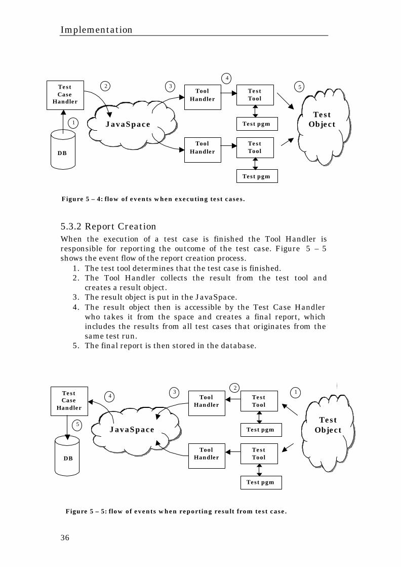
5.3.2 Report Creation When the execution of a test case is finished the Tool Handler is responsible for reporting the outcome of the test case. Figure 5 – 5 shows the event flow of the report creation process.
1. The test tool determines that the test case is finished. 2. The Tool Handler collects the result from the test tool and
creates a result object. 3. The result object is put in the JavaSpace. 4. The result object then is accessible by the Test Case Handler
who takes it from the space and creates a final report, which includes the results from all test cases that originates from the same test run.
5. The final report is then stored in the database.
Figure 5 – 5: flow of events when reporting result from test case.
Figure 5 – 4: flow of events when executing test cases.
Tool Handler
Tool Handler
Test pgm
Test Tool
Test pgm
Test Tool
Test Object
DB
JavaSpace
Test Case
Handler
1
.
2
. 3
. 4
.
5
.
Tool Handler
Tool Handler
Test pgm
Test Tool
Test pgm
Test Tool
Test Object
DB
JavaSpace
Test Case
Handler
1
.
2
. 3
.
4
. 5.
Implementation
37
5.3.3 Communication Mechanisms and Leasing The protocol used between Test Case Handler, Report Handler and Tool Handlers is a message-based protocol with messages represented in XML. The message body contains either a tool handler interface definition, a task document or a result document. When a Tool Handler is started it will post its interface definition in the JavaSpace. Every message posted in the JavaSpace has a lease time, which indicates for how long the message is valid. The Tool Handler will renew that lease until either the message is removed from the space or the tool handler is taken down. As soon as the interface definition is posted the other systems will be able to use the corresponding test tool and the Tool Handler starts looking for a task message in the JavaSpace. To retrieve a message from the space a request that includes a template message is sent to the space. The template message is an empty message of the desired type. For example, sending an empty task message results in retrieval of a message containing a task document. When the JavaSpace receives a request including a template message it performs a matching operation on the entries it is currently holding. This matching mechanism makes use of attributes in the messages, these attributes enables a more fine-grained matching. Examples of attributes are the hostname attribute, which specifies that this task message is aimed at a specific host, and the group and order attributes, which specifies that this task object is part of a certain group and that it must be executed in a specific order within that group. Attributes can easily be added or removed from the messages enabling easy extensions of the matching mechanism. The Tool Handler implementation is not restricted or controlled by any specifications or interfaces. The only demands are that it must be able to interact with the JavaSpaces service and that it communicates through the task and report messages. The body of the task message is the task XML document which is created using a specific Tool Handler’s interface definition.
Evaluation
38
6 Evaluation The model for automated verification of functionality was implemented in Java as a prototype to illustrate the concepts and to evaluate the design decisions taken. The evaluation shows that this model can simplify the verification process. The implementation of the prototype was done with a few critical design issues in mind. These critical design issues were extendibility, easiness of use and robustness.
• Extendibility – since the test environment frequently changes the system must be flexible in terms of configuration. The test case document should contain as little information about the environment as possible and the system should not require a lot of configuration.
• Easiness of use – the system must be easy to incorporate in the every day work. This means that it must be a simple task to create the test case documents as well as to execute them.
• Robustness – the system must be able to continue if one or several test tools go down. The system cannot rely on the test tools to be free from bugs and always work as expected.
It should be noted that execution and response times of the different systems are not critical issues. This arises from the fact that the execution time of the test tools are several orders of magnitude larger than the execution time of the rest of the system. For example it does not matter if the time to send a message to a Tool Handler is a millisecond or a second when the execution time of the test tool is about five minutes.
6.1 Describing test cases in XML The choice of describing test cases in XML is based on several factors. Firstly XML is simple to use, both from a system development point of view and from the end users point of view. The basic criteria is that the test cases must be represented in a format that can be interpreted by a computer program and an alternative could be to represent test cases as Java classes. This would be possible and in some cases it might be a good idea. Since Java is a programming language it would let the test case creator do virtually anything from a test case. There are a few downsides to this approach, though, of which easiness of use is one. The test case creator must have some knowledge of Java and the result would not be a document readable by a non-programmer. When using XML, on the other hand, the test case document can be converted to, for example, HTML or PDF and read by anyone, a great benefit if test cases are to be reviewed by non-programmers.

Evaluation
39
To describe the test cases in XML documents instead of MS Word documents, as they are today, will be slightly more time consuming. Mostly because of the more formal way a test case must be described in order to let the Tool Handler interpret the information contained in the document. The test case creator also must get acquainted to the XML editor, but this should be pretty straightforward and not take much time.
6.2 XML Editors Using an XML editor together with a DTD to create test cases is a very simple approach but it is not optimal when it comes to easiness of use. The problem with XML editors is that they are to general, they do not help the user to validate the content of a document – just to validate the structure. To ensure that a computer program can interpret the document both the content and the structure must be validated. There are two possible solutions to this problem. The first solution would be to use an XML editor that supports XML Schema. XML Schemas are much more powerful than DTDs because they include, amongst other things, the possibility to restrict values of the data in a document as well as the structure. The problem with this solution, however, is that there are currently no XML editors with XML Schema support available. The other solution would be to create a new customized application that takes an XML Schema as input and dynamically creates a graphical user interface with which the user can create XML documents by simply choosing values from, for example, drop down boxes or lists of alternatives. The problem with this approach is, of course, that it will take some time to create this application and with the limited time of this project it has not been possible to realize this solution The XML editor in combination with a DTD has been chosen because of the simplicity it brings from the development perspective.
6.3 The Distribution Mechanism By adding Jini to the system we benefit through the possibility to locate the currently available Tool Handlers automatically. This is an important feature in a networking environment that frequently changes since the need for configuration of the system is minimized. By adding the JavaSpaces service to the system we achieve a way to synchronise and distribute the test cases over the network. We also get the possibility to incorporate an arbitrary number of test tools in the test case execution.
Evaluation
40
The Test Case Handler and Tool Handlers communicate through the JavaSpaces service. A different approach would be to implement them as Jini services. Being Jini services they would have the ability to locate each other and then perform direct communication through e.g. RMI. This approach is harder to implement, though, and there are no obvious benefits of such a solution. The JavaSpaces service also makes the system easier to administrate since it is simple to query it for the number of pending tasks and the number of active Tool Handlers at any given point in time. Since every message is passed through the JavaSpaces service it might end up as a bottleneck, but this is neither very believable, the space can hold up to a million messages depending on the machine it is running on, nor a great problem since a new JavaSpaces service can be started and used in parallel.
Conclusions and Future Work
41
7 Conclusions and Future Work The objective of this thesis was to develop a model that allows automated verification of functionality in the IP-BSS development project. A prototype of the model for automated verification of functionality was implemented to illustrate the concepts and to evaluate the design decisions taken. The evaluation shows that this model can simplify the verification process. The model makes use of existing test tools for the test case execution and the test cases are described in XML. It was shown how the Jini technology can be used to dynamically locate and interact with resources on the network as a means to achieve a dynamic and failsafe system with minimal configuration requirements. Describing test cases in XML proved to be both a fairly straightforward process from the test case creator’s point of view as well as from the application developer’s. The biggest challenge of a project of this kind is to integrate it into the daily work. The model has proved to work in small scale but will need continuous development efforts during the process of getting it into everyday use. This arises from the fact that new test tools will be incorporated in the model and they need handlers that can control them. The implementation of the model described in this thesis can be improved in several ways. The most important enhancement would be to simplify the test case creation process by developing a customised application that let the user create valid XML documents in a more controlled way than an XML editor is capable of. Another important enhancement would be to replace the DTDs with XML Schemas. XML Schemas are more flexible and it would make the DTD Generator more powerful. DTDs do not explicitly support the kind of fragmentation that is needed to incorporate the Tool Handler interface definitions into the one DTD that the test case creator uses. Another possible enhancement would be to include some mechanism for order control of test case execution and repetitive test case execution. It could, for example, be interesting to do repeated executions of the same test case with slightly different environment set-ups for each execution.
References
42
8 References [1] Natanya Pitts-Moultis and Cheryl Kirk, XML Black Book,
Coriolis Technology Press 1999, ISBN 1-57610-284-X [2] Tim Bray (Textuality and Netscape), Jean Paoli (Microsoft), C.
M. Sperberg-McQueen (University of Illinois at Chicago), Extensible Markup Language (XML) 1.0, W3C Recommendation 10-February-1998
[3] Tim Bray, The Annotated XML Specification, 1999, http://www.xml.com/axml/axml.html
[4] David C. Fallside (IBM), XML Schema Part 0: Primer, W3C Working Draft, 25 February 2000
[5] Henry S. Thompson (University of Edinburgh), David Beech (Oracle Corp.), Murray Maloney (Commerce One), Noah Mendelsohn (Lotus Development Corporation), XML Schema Part 1: Structures, W3C Working Draft, 7 April 2000
[6] David Megginson, SAX 1.0: The Simple API for XML, url: http://www.megginson.com/SAX/SAX1/index.html
[7] Vidur Apparao (Netscape), Steve Byrne (Sun), Mike Champion (ArborText), Scott Isaacs (Microsoft), Ian Jacobs (W3C), Arnaud Le Hors (W3C), Gavin Nicol (Inso EPS), Jonathan Robie (Texcel Research), Robert Sutor (IBM), Chris Wilson (Microsoft), Lauren Wood (SoftQuad, Inc), Document Object Model (DOM) Level 1 Specification, url: http://www.w3.org/TR/REC-DOM-Level-1
[8] Paul V. Biron (Kaiser Permanente, for Health Level Seven), Ashok Malhotra (IBM), XML Schema Part 2: Datatypes, W3C Working Draft 07 April 2000
[9] James Clark, XSL Transformations (XSLT) Version 1.0, url: http://www.w3.org/TR/xslt
[10] Mark Johnson, Programming XML in Java, Part 1, JavaWorld March 2000
[11] Mark Johnson, Programming XML in Java, Part 2, JavaWorld April 2000
[12] Mark Johnson, Programming XML in Java, Part 3, JavaWorld July 2000
[13] Robert Husteadt, Mapping XML to Java, Part 1, JavaWorld August 2000
[14] Jason Monberg, How Sparks.com Uses XML and XSL for Dynamically Generated Pages, CNet June 2000, http://www.builder.com/Programming/XMLToday/index.html
[15] XMLInfo.com, The XML Information Site, http://www.xmlinfo.com
[16] XML Magazine, url: http://xmlmag.com [17] Apache, The Apache XML Project, http://xml.apache.org [18] JDOM, The JDOM Open Source Project, http://jdom.org [19] Java Technology and XML, SUN's XML Pages,
http://java.sun.com/xml
References
43
[20] World Wide Web Consortium (W3C), www.org [21] SoftQuad: XML solutions for e-business, url:
http://www.xmetal.com [22] Jan Newmarch, Jan Newmarch's Guide to JINI Technologies,
http://pandonia.canberra.edu.au/java/jini/tutorial/Jini.xml [23] Ken Arnold, Bryan Osullivan, Robert W. Scheifler, Jim Waldo,
Ann Wollrath, Bryan O'Sullivan, The Jini(TM) Specification (The Jini(TM) Technology Series), Addison-Wesley Pub Co; ISBN: 0201616343
[24] Eric Freeman, Susanne Hupfner, Ken Arnold, JavaSpaces(TM) Principles, Patterns and Practice (The Jini(TM) Technology Series), Addison-Wesley Pub Co; ISBN: 0201309556
[25] Eric Freeman and Susanne Hupfner, Make Room For JavaSpaces, http://www.javaworld.com/javaworld/jw-11-1999/jw-11-jiniology-2.html
[26] Nicholas Carriero, David Gelernter, Linda in Context, CACM 32(4): 444-458 (1989), http://www.informatik.uni-trier.de/~ley/db/journals/cacm/cacm32.html#CarrieroG89
[27] JUnit, Testing Resources for Extreme Programming, url: http://www.junit.org
[28] IBM alphaWorks, Provides developers direct access to IBM's emerging "alpha-code" technologies. The latest software technologies, for download and evaluation, http://www.alphaworks.ibm.com/
Appendix A: Class Diagrams
44
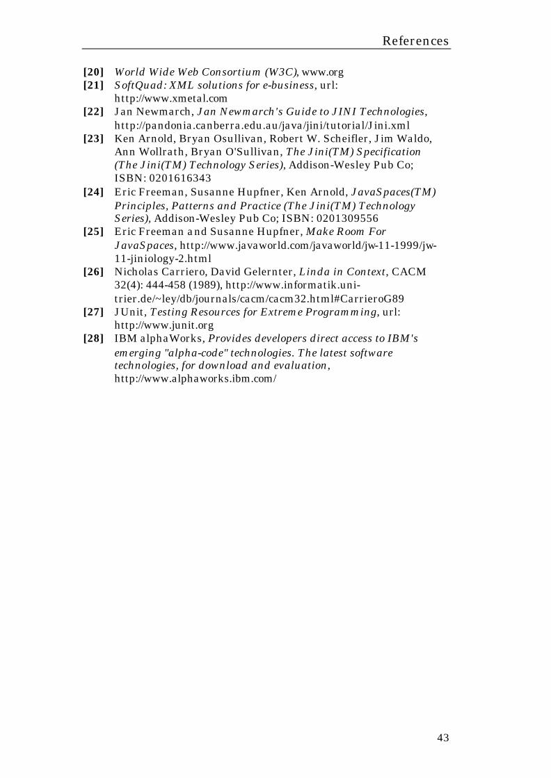
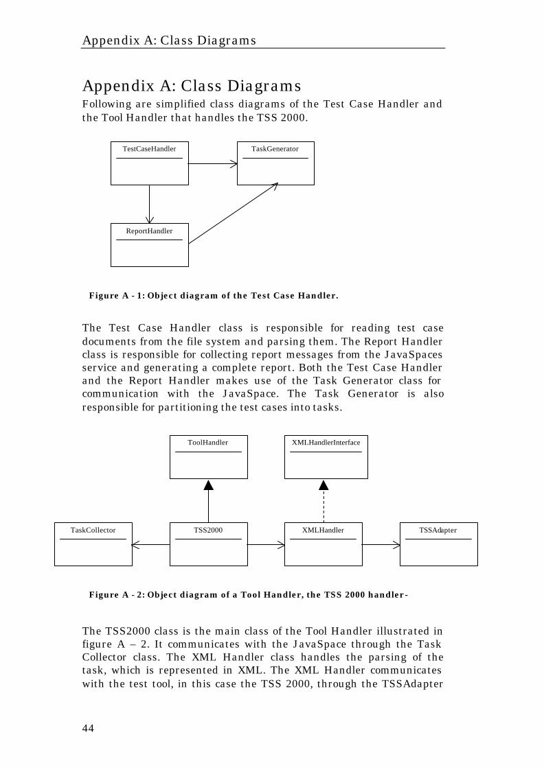
Appendix A: Class Diagrams Following are simplified class diagrams of the Test Case Handler and the Tool Handler that handles the TSS 2000. The Test Case Handler class is responsible for reading test case documents from the file system and parsing them. The Report Handler class is responsible for collecting report messages from the JavaSpaces service and generating a complete report. Both the Test Case Handler and the Report Handler makes use of the Task Generator class for communication with the JavaSpace. The Task Generator is also responsible for partitioning the test cases into tasks. The TSS2000 class is the main class of the Tool Handler illustrated in figure A – 2. It communicates with the JavaSpace through the Task Collector class. The XML Handler class handles the parsing of the task, which is represented in XML. The XML Handler communicates with the test tool, in this case the TSS 2000, through the TSSAdapter
TaskGenerator
TestCaseHandler
ReportHandler
Figure A - 1: Object diagram of the Test Case Handler.
Figure A - 2: Object diagram of a Tool Handler, the TSS 2000 handler-
TaskCollector
TSS2000
ToolHandler
XMLHandler
TSSAdapter
XMLHandlerInterface
Appendix A: Class Diagrams
45
class. The TSSAdapter class provides a set of methods that are used to send instructions to the test tool. In the Tool Handler implementation for the FT Driver, for example, the three classes TSS2000, XMLHandler and TSSAdapter are replaced by the classes FTDriver, XMLHandler and FTDAdapter. The different Tool Handler implementations are located in different packages, which means that there are no restrictions on the naming of these classes.
Appendix B: User Manual
46
Appendix B: User Manual
Introduction This document gives an introduction to the Integration and Verification Test Model (IVTM), a system for performing automated verification of functionality within the RNS development project. The IVTM is a system that uses existing test tools to execute test cases defined in XML representations of test specifications.
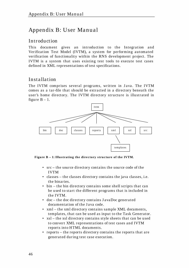
Installation The IVTM comprises several programs, written in Java. The IVTM comes as a tar-file that should be extracted in a directory beneath the user’s home directory. The IVTM directory structure is illustrated in figure B – 1.
• src – the source directory contains the source code of the IVTM
• classes – the classes directory contains the java classes, i.e. the binaries.
• bin – the bin directory contains some shell scripts that can be used to start the different programs that is included in the IVTM.
• doc – the doc directory contains JavaDoc generated documentation of the Java code.
• xml – the xml directory contains sample XML documents, templates, that can be used as input to the Task Generator.
• xsl – the xsl directory contains style sheets that can be used to convert XML representations of test cases and IVTM reports into HTML documents.
• reports – the reports directory contains the reports that are generated during test case execution.
ivtm
reports xml classes bin doc src xsl
Figure B – 1: Illustrating the directory structure of the IVTM.
templates
Appendix B: User Manual
47
The installation does not require anything in addition to extracting the tar-file.
Test Case Representation The test case documents are described in XML and created using an XML editor. To aid the test case creator a DTD can be used together with the XML editor. The DTD should be generated by the supplied DTD Generator. Each XML document will contain an XML representation of one test case. To make it easier to setup an automated test including several test cases the test cases can be grouped together in a test suite document. For example, the test cases that correspond to a certain test specification can be grouped together to a test suite enabling easy execution of all test cases from a certain test specification. A sample test case document is depicted in figure B – 2. This test case makes use of three test tools; the FTDriver for the setup phase, the TSS 2000 for the actual test case and the TestHarness for the cleanup phase. To create a new test case document this example document can be used as a base and be modified as needed. To verify that the created document is correct, in terms of XML syntax, the validate.sh script can be used (see the System Components section).
Appendix B: User Manual
48
<?xml version="1.0" ?> <Instruction> <Header> <No>1/152 41-FAY 223 10</No> <Title>3.1.1, Test case: Requesting Full rate Speech version 1, Successful</Title> <Prepared>Britney Spears</Prepared> <Approved>Eminem</Approved> <Date>2000-09-18</Date> <Rev>PA89</Rev> </Header> <Purpose>Sending 'Assignment Request' with Full rate Speech version 1, which is a supported Service, is send to RNS.</Purpose> <Prerequisites>Add an extra cell.</Prerequisites> <Requirement> Ref. 9-2</Requirement> <Preparation> <Tool> <TSS instance="tss01"> Used to simulate MS, BTS, AGW and MSC </TSS> <FTD instance="ftd01"> Used to add an extra cell </FTD> <HARNESSS instance="harness01"> Clean up after execution </HARNESS> </Tool> <Environment> <Clearcase view="erardlh_view" /> </Environment> </Preparation> <Implementation hostname="purple103.era-a.ericsson.se"> <Setup instance="ftd01"> <FTDriver> <TestSuite>cmmo.CmMoSuite</TestSuite> </FTDriver> <Result> <Output test_program="" timeout="120" /> <Description>Successful if no errors are reported.</Description> </Result> </Setup> <Action instance="tss01"> <TSS2000 useAdapter="true"> <File>ASSIGNMENT</File> <Parameters> <Parameter test_program="Assignment_MSC" param_name="FULL_RATE_Version1" value="1" /> </Parameters> </TSS2000> <Result> <Output test_program="Assignment_MSC" timeout="120">Assignment completed</Output> <Output test_program="Assignment_MSC">Testcase 124 completed</Output> <Description>If the 'Assignment Request' is successfully terminated, an 'Assignment complete' will be send to the MSC.</Description> </Result> </Action> <Cleanup instance="harness01"> <TestHarness> <JariScript>HarnessLoad.txt</JariScript> </TestHarness> <Result> <Output test_program="" timeout="120" /> <Description> Successful if no errors are reported </Description> </Result> </Cleanup> </Implementation>
</Instruction>
Figure B – 2: An example of a test case document.
set-up
execution
preparation
cleanup
Appendix B: User Manual
49
Test Case Execution The test case execution involves the following programs; the taskgenerator, the jini lookup service, the javaspaces service and one or several of the tool handlers. The Jini Lookup service and the JavaSpaces service are not part of the IVTM system, they are provided by Sun Microsystems, but still necessary. The TaskGenerator is started by executing the shell script start_TaskGenerator.sh. with, as argument, the path to the test case document or the test suite document that represents the test case. [~/ivtm/bin]$ ./start_TaskGenerator.sh ../xml/testcase01.xml The Task Generator will now read the test cases and create task objects that can be distributed to the available Tool Handlers. The actual test case execution is controlled by the Tool Handler applications. Therefore, to get going a Tool Handler must be started. There are currently three Tool Handlers available; the TSS2000 Handler, the FTDriver Handler and the TestHarness Handler. To start these handlers try one of the following: [~/ivtm/bin]$ ./start_TSS2000.sh [~/ivtm/bin]$ ./start_FTDriver.sh [~/ivtm/bin]$ ./start_TestHarness.sh When a Tool Handler is started it will contact the JavaSpaces service and look for a test case to execute. NOTE: There should never be more than one Tool Handler executing on the same machine. Each Tool Handler will when started look for a test case and then start executing it. If there are several Tool Handlers running on the same machine the corresponding test tools might interfere with each other.
System Components The IVTM comprises several system components, or programs. The most important of these programs are the Task Generator and the Tool Handlers. These are the programs that are used to perform the actual test case execution. However, there are also a few programs to simplify the test case creation process and there are also the Jini Lookup Service and the JavaSpaces Service that are used for the distribution of test cases among the test tools. The different programs can be configured by setting properties in their corresponding property files,
Appendix B: User Manual
50
located in the classes directory. Following is an overview of the different system components. Task Generator The Task Generator parses the test case documents and creates task objects. These task objects are then stored in the JavaSpace. When the task objects are stored in the JavaSpace the Task Generator begins to wait for results. When the results are found the Task Generator creates a report, in XML, that reflects the results of the executed test cases. The report will be stored in a directory with a name on the format “YYYYMMDD_HHMMSS”, i.e. the date and time of the test case execution. This directory will be created in the reports directory beneath the ivtm root, unless something else is specified in the taskgenerator.properties file located in the classes directory. TSS2000 Handler The TSS2000 Handler searches for tasks in the JavaSpace and as soon as a task is found it takes it and starts to execute it. The actual test case execution is handled by the TSS 2000 itself. When the execution of a test case is finished the TSS2000 Handler collects the result from the TSS 2000 and creates a report object that is stored in the JavaSpace. The TSS 2000 Handler uses the TSS Remote Control to communicate with the TSS 2000. When the TSS2000 Handler is started it stores its interface definition, in the form of a DTD fragment, in the JavaSpace. This interface definition defines the XML tags that can be interpreted by this handler.
FTDriver Handler The FTDriver Handler retrieves tasks from and returns results to the JavaSpace in the same manner as the TSS2000 Handler. The FTDriver is able to create reports in HTML, why the Task Generator can use these rather than create its own reports. When the FTDriver Handler is started it stores its interface definition, in the form of a DTD fragment, in the JavaSpace. This interface definition defines the XML tags that can be interpreted by this handler. TestHarness Handler The TestHarness Handler retrieves tasks from and returns results to the JavaSpace in the same manner as the TSS2000 Handler. The TestHarness does currently not allow the handler to determine if a test case execution is successful or not, which implies that the report will not contain any information regarding the outcome of a test case. This is of course a big drawback but it is probably addressed in a later release of the TestHarness. When the TestHarness Handler is started it stores its interface definition, in the form of a DTD fragment, in the JavaSpace. This interface definition defines the XML tags that can be interpreted by this handler.
Appendix B: User Manual
51
DTD Generator The DTD Generator collects Tool Handler interface definitions from the JavaSpace and assembles them into a complete DTD that can be used by the test case creator. The DTD Generator should be used when a new Tool Handler is created in order to incorporate its interface definition into the DTD used by test case creators. Validator Used to validate that an XML document conforms to a given DTD. Makes use of the Xerces-J validating parser. XML2HTML Converter Used to convert, or transform, XML documents into HTML documents. Makes use of the Xerces-J parser as well as the Xalan XSLT processor. Jini Lookup Service The Jini Lookup Service is used by the IVTM system components to locate the JavaSpaces service. There is only need for one instance of the Jini Lookup Service to be running. However, multicast messages are used to locate the lookup service itself why it is necessary to use different lookup services on networks separated by a router that does not forward multicast messages. See the documentation provided by SUN Microsystems for details on the Jini Lookup Service.
JavaSpaces Service The JavaSpaces Service is a distributed object storage where Java objects can be temporarily stored. There is only need for one instance of the JavaSpaces Service to be running. The tasks and report objects stored in the JavaSpace are marked with id numbers to prevent them from interfering with each other. See the documentation provided by SUN Microsystems for details on the JavaSpaces Service.
SpaceBrowser The SpaceBrowser can be used to browse the objects the JavaSpace is currently holding. This is very useful when debugging or gaining an understanding of the system. See the documentation provided by SUN Microsystems for details on the SpaceBrowser.
Shell Scripts The shell scripts described in this section are all located in the bin directory, start_TSS2000.sh Tool Handler that executes test cases using the TSS 2000 test tool. Example: [~/ivtm/bin]$ ./start_TSS2000.sh
Appendix B: User Manual
52
start_FTDriver.sh Tool Handler that executes test cases using the FTDriver test tool. Example: [~/ivtm/bin]$ ./start_FTDriver.sh start_TestHarness.sh Tool Handler that executes test cases using the Test Harness test tool. Example: [~/ivtm/bin]$ ./start_TestHarness.sh start_TaskGenerator.sh The Task Generator reads and parses test cases represented in XML and creates task objects. The task objects are then stored in the JavaSpace where they can be located and from which they can be retreived, by Tool Handlers. Format:
start_TaskGenerator.sh <xml-file> Example: [~/ivtm/bin]$ ./start_TaskGenerator.sh testcase01.xml start_DTDGenerator.sh The DTDGenerator is used to create a DTD that can be used by the test case creator. The DTD comprises the different Tool Handlers interface definitions. Format: start_DTDGenerator.sh <dtd-file> Example: [~/ivtm/bin]$ ./startDTDGenerator.sh test.dtd validate.sh validate.sh is a small program that can be used to validate that XML documents conforms to a given DTD. Format: validate.sh <xml-file> Ex: [~/ivtm/bin]$ ./validate.sh testcase01.xml Result (successful):
[Beginning of document] [End of document]
Result (unsuccessful): [Beginning of document] <Error message containing information about the error, such as row number etc.> [End of document]
Appendix B: User Manual
53
xml2html.sh xml2html.sh converts an XML document into HTML using an XSL style sheet. Format: xml2html.sh <xml-file> <xsl-file> <output-file>
Example: [~/ivtm/bin]$ ./xml2html.sh test01.xml test.xsl example.html space_browser.sh takes a snapshot of the JavaSpace and presents the user an overview of all the objects currently stored in the space. Example: [~/ivtm/bin]$ ./space_browser.sh