Embed Size (px)
Citation preview
ELECTAIC~aWEAIWITEmlAEIE~ACH
ELSEVIER Electric Power Systems Research 42 (1997) 225-228
A model for induction motor aggregation for power system studies
P. Pillay a,*, S.M.A. Sabur b, M.M. Haq b
a Department of Electrical and Computer Engineering, Clarkson University, Box 5720, Potsdam, NY 13699-5720, USAb Department of Electrical Engineering, University of New Orleans, New Orleans, LA 70148, USA
Received 8 November 1996
Abstract
This paper proposes a new model for aggregating a group of induction motors for system studies. The aggregation methoddeveloped here is based on the transformer-type variation of the equivalent circuit. A grouping criteria is used to classifyhomogeneous motors into different groups. The validity of the proposed method is verified by comparing the results obtainedfrom the aggregate motor with the sum of the individual motors. @ 1997 Elsevier Science S.A.
Keywords: Induction motors; Aggregation methods
1. Introduction
The simulation of a large group of induction motorsfor system studies can be time consuming. In order toreduce the computation time, reduced order modellingis used to represent a group of motors with one or moreaggregate motors. The accuracy of the results obtainedfrom the aggregate motors depends in part on theassumptions made in the derivation of the aggregatemotor and varies from method to method. This subjectof the aggregation of induction machines for systemstudies has received a fair amount of attention in theliterature [1-6].
In [1], to develop an aggregation model the approxi-mate equivalent circuit is used with stator resistancebeing neglected. In the derivation of the model, thebasic assumption is of power invariance between theaggregate motor and the sum of the individual motors.Since the skin-effect has a strong influence on theperformance of induction motors, in [2] the equivalentcircuit is represented by seven electrical parametersinstead of five. In [3], the motor parameters are calcu-lated from standard specifications which, together withnetwork and load data, are incorporated into an admit-tance matrix. The inertia and running slip are chosen tominimize the error between the transient response of
* Corresponding author. Tel.: + I 315 2686509; fax: + I 3152687600.
0378-7796/97/$17.00 ~ 1997 Elsevier Science S.A. All rights reserved.PII 80378-7796(96)01211-4
the system and its equivalent. In [4], the unknownparameters of the equivalent motor are estimatedthrough a weighted-least squares procedure. In [5],Thevenins theorem along with selected characteristicsof the induction machine are used in the calculation ofthe parameters of the equivalent machine. In [6], afictitious impedance is introduced to convert the simpleequivalent circuit into a circuit with parallel elementsonly.
In this paper, a transformer-type equivalent circuit[7] is used to represent an induction motor. Five motorsare used in the current work to obtain the aggregatemotor. Results from the aggregate motor are comparedwith that obtained from the sum of the individualmotors.
2. Development of the transformer-type equivalentcircuit model for the induction motor
Usually induction motors are represented by theconventional equivalent circuit model in Fig. 1. But inthis paper, an alternative type of equivalent circuit,called the transformer-type equivalent circuit, is used asshown in Fig. 2.
The two circuits are equivalent to each other. Theparameters of the two circuits are related in the follow-mg way:
Zo = Z, + Zm (2.1)
226
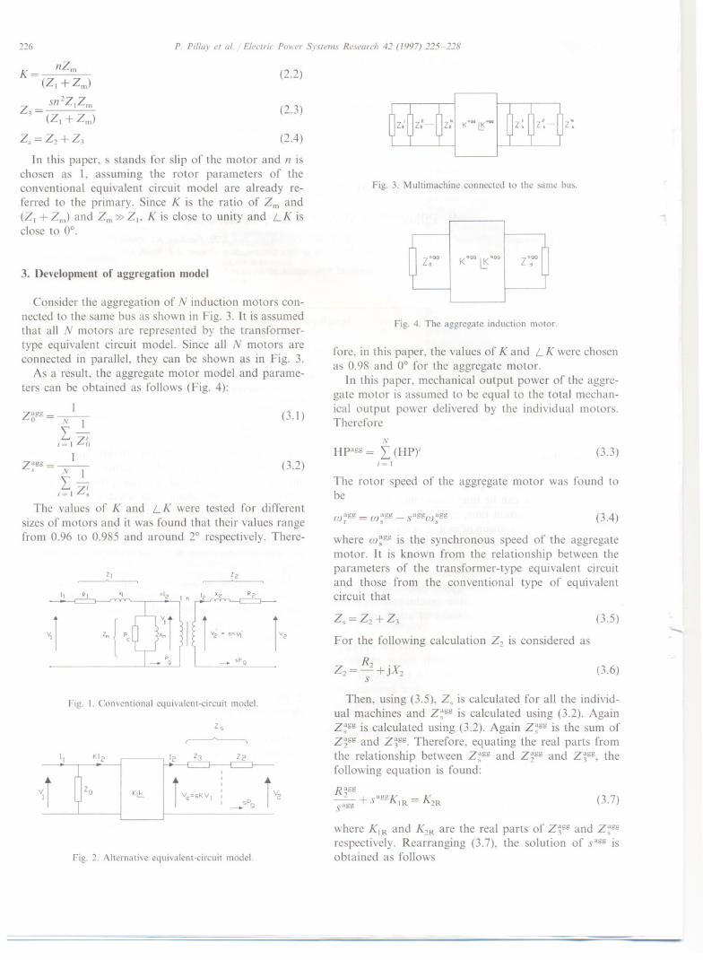
nZmK--
- (Zl +Zm)
Sn2ZIZm
Z3 = (Zl + Zm)
Zs = Z2 + Z3
(2.2)
P. Pillay et al. / Electric Power Systems Research 42 (1997) 225-228
(2.3)
(2.4)
In this paper, s stands for slip of the motor and n ischosen as 1, assuming the rotor parameters of theconventional equivalent circuit model are already re-ferred to the primary. Since K is the ratio of Zm and(ZI + Zm) and Zm» Z1> K is close to unity and LK isclose to 0°.
3. Development of aggregation model
Consider the aggregation of N induction motors con-nected to the same bus as shown in Fig. 3. It is assumedthat all N motors are represented by the transformer-type equivalent circuit model. Since all N motors areconnected in parallel, they can be shown as in Fig. 3.
As a result, the aggregate motor model and parame-ters can be obtained as follows (Fig. 4):
Izagg --
0 - N ILi
i~1 Zo
(3.1)
1zagg =-
S N ILi
i~l Zs
The values of K and LK were tested for differentsizes of motors and it was found that their values rangefrom 0.96 to 0.985 and around 2° respectively. There-
(3.2)
'2~
R2
-+ SPg
Fig. 1. Conventional equivalent-circuit model.
Zs
~
Fig. 2. Alternative equivalent-circuit model.
z:
Fig. 3. Multimachine connected to the same bus.
z;gg Kogg ~Ogg zo:g
Fig. 4. The aggregate induction motor.
fore, in this paper, the values of K and LK were chosenas 0.98 and 0° for the aggregate motor.
In this paper, mechanical output power of the aggre-gate motor is assumed to be equal to the total mechan-ical output power delivered by the individual motors.Therefore
N
Hpagg = L (HPYi~ I
(3.3)
The rotor speed of the aggregate motor was found tobe
agg - agg agg aggCOr -COs -S COs (3.4)
where co~ggis the synchronous speed of the aggregatemotor. It is known from the relationship between theparameters of the transformer-type equivalent circuitand those from the conventional type of equivalentcircuit that
Zs = Z2 + Z3
For the following calculation Z2 is considered as
(3.5)--
R2 .Z2 =-+JX2S
(3.6)
Then, using (3.5), Zs is calculated for all the individ-ual machines and z~gg is calculated using (3.2). Againz~gg is calculated using (3.2). Again z~gg is the sum ofz~gg and z~gg. Therefore, equating the real parts fromthe relationship between z~gg and Z2gg and z~gg, thefollowing equation is found:
R aggK~+SaggK1R= 2R
sagg(3.7)
where KIR and K2R are the real parts of z~gg and z~ggrespectively. Rearranging (3.7), the solution of sagg isobtained as follows
'I
VI] {<
I[ KI2 12 ZJ Z2
r
r r Vs=sKVI
'
r V2
'Zo K '
,,
_SPg
P. Pillay et al. / Electric Power Systems Research 42 (1997) 225-228
sagg = K2R I J(K2R)2 - 4K1RR2gg2KlR
Here R2ggis unknown and obtained from the differencebetween z~gg and Z3gg calculated without consideringslip.
Considering the conservation of kinetic energy, thefollowing relation is used:
(3.8)
N
(OJ i
)2
Jagg = I Ji OJa;gi~ 1 r(3.9)
In this paper, five different sizes of motors are con-sidered. Conventional equivalent circuit parameters of
2500
20001500
Q. 1000~ 500.£c 0'"~ -500:Ju -1000
-1500
-2000
-25000.00 0.32 0.64 0.96 1.28 1.60 1.92 2.24 2.56 2.88 3.20
Time in see
Fig. 5. Stator phase A current of the aggregate motor.
2500
2000
1500
c. 1000
~ 500.£c 0'"~ -500"u
-1000
-1500
- 2000
-25000.00 0.32 0.64 0.96 1.28 1.60 1.92 2.24 2.56 2.88 3.20
Time in Sec
Fig. 6. Summation of stator phase A currents of the individualmotors.
227
3000
2660
2320
1980:>
~ 1640
.~ 1300
? 9600
>- 620
280
-60
-4000.00 0.32 0.64 0.96 1.2B 1.60 1.92 2.24 2.56 2.BB 3.20
Time in Sec
Fig. 7. Electromagnetic torque of the aggregate motor.
3000
2660
2320
19BO:>~ 1640
.~ 1300~2' 9600
t- 620
280
-60
-4000.00 0.32 0.64 0.96 1.2B 1.60 1.92 2.24 2.56 2.88 3.20
Time in Sec
Fig. 8. Summation of electromagnetic torque of the individual mo-tors.
all the five motors as well as the aggregate motorobtained are given in the Table 1.
4. Grouping criterion
The purpose of a grouping criterion is to identify andgroup homogeneous motors. The inertia and open cir-cuit time constant are often used to classify motors. In[2], the authors have developed a grouping criterionthat may be expressed as
G=HylY. (4.1)
where
(Xl + X2)
y= (R( +R2)(4.2)
XmIY.=-
R2
The group is homogeneous if
(4.3)
I ~ (Gmax/Gmin)~ 2.5 (4.4)
Based on the above grouping criterion, the disparatesizes of motors are classified into different groups. Thenaggregation is done for different motor groups sepa-rately to find aggregate motors from each group.
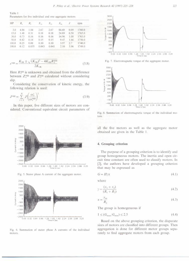
Table 1Parameters for five individual and one aggregate motors
HP Rs R, XIs Xh Xm J rpm
3.0 4.86 1.84 2.67 2.67 84.68 0.09 1760.015.0 1.48 0.31 0.18 0.18 24.89 0.50 1765.030.0 0.73 0.16 0.16 0.16 14.96 1.00 1765.050.0 0.42 0.14 0.15 0.15 9.47 1.66 1750.0
100.0 0.25 0.08 0.10 0.10 3.97 2.7 1740.0198.0 0.12 0.035 0.043 0.041 2.10 5.96 1749.0
5. Results
P. Pillay et al. / Electric Power Systems Research 42 (1997) 225-228228
In this section, results have been presented for theaggregate motor as well as the sum of the individualmotors to compare the performance of the aggregatemotor obtained. Table 1 presents the necessary electri-cal and mechanical parameters for five individual andone aggregate motor. Here, all the individual and ag-gregate motors are connected to a 460 V bus and thenumber of poles of each motor is 4.
In the simulation, the motors are first started fromstandstill to steady-state. Then the source is discon-nected from the motors for 134 ms (8 cycles) andreclosed. The action of the circuit breaker in practice isrepresented by increasing the source resistance from itsoriginal value to the value of 500 Q. This change ofresistance is carried out at the zero level of each phasecurrent to simulate the extinguishing of the current at acurrent zero.
Fig. 5 shows the stator phase A current of theaggregate motor while Fig. 6 shows the sum of thestator phase A currents of the individual motors.Again, Fig. 7 shows the electromagnetic torque of theaggregate motor while Fig. 8 shows the sum of theelectromagnetic torques of the individual motors. Acomparison between the two sets of curves shows satis-factory correlation.
6. Conclusions
In this paper, a new model has been developed toaggregate induction motors. To develop this model, atransformer-type equivalent circuit of the induction mo-
tor is used. A grouping criterion is used to classifydifferent motors into different groups for better results.The results using the aggregate motor are compared tothat obtained from the sum of the individual motors.
The results are acceptable.
Acknowledgements
The Authors acknowledge EPRI and Entergy Corpo-ration for funding this work.
References
[I] M.M. Abdel Hakim and G.J. Berg, Dynamic single-unit repre-sentation of induction motor groups, IEEE Trans. Power Appar.Syst., PAS-95 (I) (Jan.jFeb. 1976).
[2] M. Akbaba and S.Q. Fakhro, New Model for single-unit repre-sentation of induction motor loads, including skin effect, forpower system transient stability studies, lEE Proc.-B, 139 (6)(Nov. 1992).
[3] G.J. Rogers, J. Di Manno and R.T.H. Alden, An aggregateinduction motor model for industrial plants, IEEE Trans. PowerAppar. Syst., PAS-103 (4) (April 1984).
[4] A.H.M.A. Rahim and A.R. Laldin, Aggregation of inductionmotor loads for transient stability studies, IEEE Trans. EnergyConv., EC-2 (1) (March 1987).
[5] M. Taleb, M. Akbaba and E.A. Abdullah, Aggregation ofinduction machines for power system dynamic studies, IEEEjPES 1994 Winter Meet., New York, New York, Jan. 30-Feb. 3,1994.
[6] D.C. Franklin and A. Morelato, Improving dynamic aggregationof induction motor models, IEEEjPES 1994 Winter Meet., NewYork, New York, Jan. 30-Feb. 3, 1994.
[7] Pragasen Pillay and Larbi Refoufi, Calculation of slip energyrecovery induction motor drive behaviour using the equivalentcircuit, IEEE Trans. Ind. Appl., 30 (1) (Jan.jFeb. 1994).


![AEIE 4th Semester Detailed Syllabus (1)makautexam.net/aicte_details/Syllabus/AEIE/sem4.pdf · 1rq kd]dugrxv duhdv (qforvxuhv ± 1(0$ dqg ,3 frghv 0hwkrgv ri 3urwhfwlrq ± ([sorvlrq](https://img.pdfslide.net/doc/110x75/5f01d6ef7e708231d4014aca/aeie-4th-semester-detailed-syllabus-1-1rq-kddugrxv-duhdv-qforvxuhv-10-dqg.jpg)