Embed Size (px)
Citation preview

IN DEGREE PROJECT COMPUTER SCIENCE AND ENGINEERING,SECOND CYCLE, 30 CREDITS
, STOCKHOLM SWEDEN 2021
A Modeling Language for Timed Automata
ERNST WIDERBERG
KTH ROYAL INSTITUTE OF TECHNOLOGYSCHOOL OF ELECTRICAL ENGINEERING AND COMPUTER SCIENCE
“If I push that button, this machine makes another machine like this machine.”

Cover illustration by Ejnar Nettelbladt

A Modeling Language forTimed Automata
Ett modelleringsspråk för tidsautomater
Author
Ernst [email protected]
Supervisors
Jesus Mauricio [email protected]
Viktor [email protected]
Examiner
Cyrille [email protected]
Friday 26th February, 2021
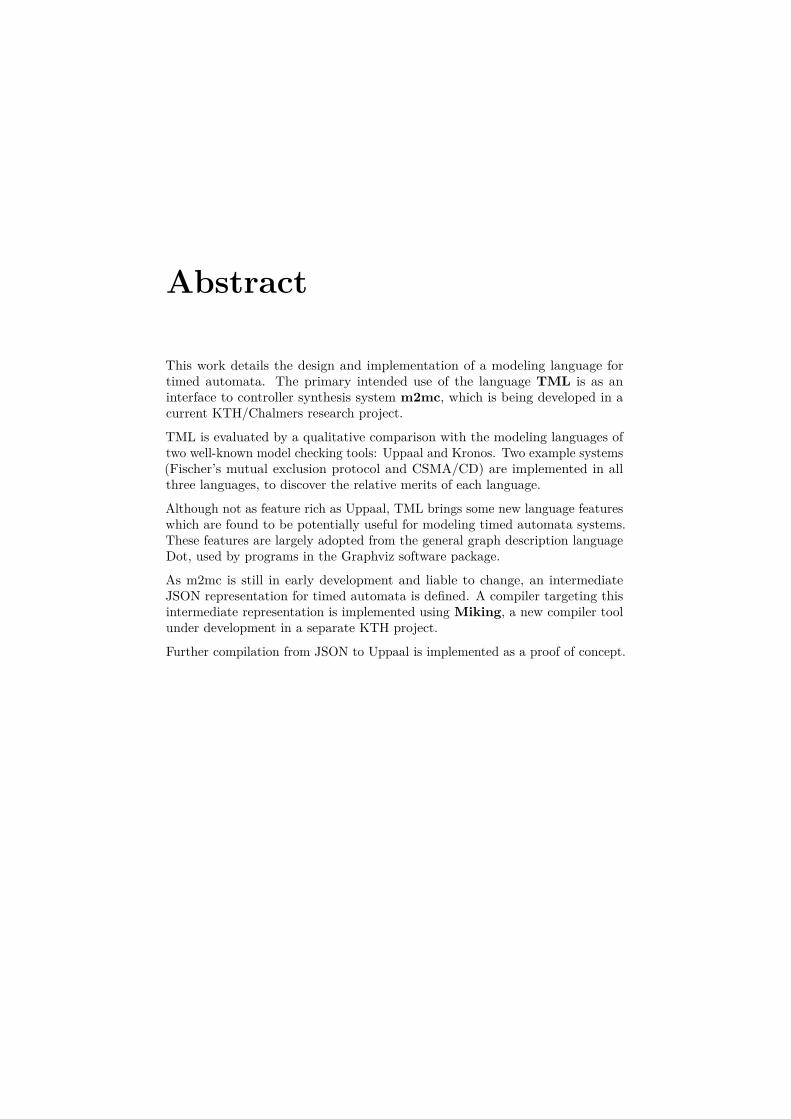
Abstract
This work details the design and implementation of a modeling language fortimed automata. The primary intended use of the language TML is as aninterface to controller synthesis system m2mc, which is being developed in acurrent KTH/Chalmers research project.
TML is evaluated by a qualitative comparison with the modeling languages oftwo well-known model checking tools: Uppaal and Kronos. Two example systems(Fischer’s mutual exclusion protocol and CSMA/CD) are implemented in allthree languages, to discover the relative merits of each language.
Although not as feature rich as Uppaal, TML brings some new language featureswhich are found to be potentially useful for modeling timed automata systems.These features are largely adopted from the general graph description languageDot, used by programs in the Graphviz software package.
As m2mc is still in early development and liable to change, an intermediateJSON representation for timed automata is defined. A compiler targeting thisintermediate representation is implemented using Miking, a new compiler toolunder development in a separate KTH project.
Further compilation from JSON to Uppaal is implemented as a proof of concept.

Sammanfattning
Detta arbete behandlar utformning och implementering av ett modelleringsspråkför tidsautomater. Språket TML:s huvudsakliga tänkta tillämpning är attfungera som ett användargränssnitt för kontrollsyntessystemet m2mc, vilketutvecklas i ett pågående forskningsprojekt på KTH och Chalmers.
TML utvärderas genom en kvalitativ jämförelse med modelleringsspråken förtvå välkända model checking-verktyg: Uppaal och Kronos. Två exempelsystem(Fischers protokoll för mutual exclusion och CSMA/CD) implementeras i varderamodelleringsspråk för att undersöka de olika språkens relativa fördelar ochnackdelar.
Fastän TML inte är lika omfattande i funktionalitet som Uppaal så bidrar språketmed en del nya funktioner, vilka baserat på utvärderingen anses kunna varaanvändbara för modellering av tidsautomatsystem. Dessa funktioner hämtas tillstor del från språket Dot, vilket används i mjukvarupaketet Graphviz för attmodellera generella grafer.
Eftersom m2mc är i tidig utveckling vore direkt integration med TML intepraktiskt användbart. Därför definieras istället ett mellanformat för tidsauto-mater i JSON. En kompilator för TML som producerar detta mellanformatimplementeras med användning av Miking, ett nytt kompilatorverktyg underutveckling i ett separat KTH-projekt.
Som ett koncepttest implementeras vidare kompilering från JSON till Uppaal.

Contents
1 Introduction 11.1 Research Questions . . . . . . . . . . . . . . . . . . . . . . . . . . 21.2 Scope . . . . . . . . . . . . . . . . . . . . . . . . . . . . . . . . . 21.3 Societal Impact . . . . . . . . . . . . . . . . . . . . . . . . . . . . 21.4 Outline . . . . . . . . . . . . . . . . . . . . . . . . . . . . . . . . 3
2 Preliminaries 42.1 Finite Automata . . . . . . . . . . . . . . . . . . . . . . . . . . . 42.2 Timed Automata . . . . . . . . . . . . . . . . . . . . . . . . . . . 5
2.2.1 Timed Safety Automata . . . . . . . . . . . . . . . . . . . 52.2.2 Synchronizing Networks of Timed Automata . . . . . . . 7
2.3 Timed Automata Applications . . . . . . . . . . . . . . . . . . . 72.3.1 Model Checking . . . . . . . . . . . . . . . . . . . . . . . 72.3.2 Controller Synthesis . . . . . . . . . . . . . . . . . . . . . 7
2.4 Compiler Construction . . . . . . . . . . . . . . . . . . . . . . . . 102.4.1 Compiler Phases . . . . . . . . . . . . . . . . . . . . . . . 102.4.2 Syntactic Sugar . . . . . . . . . . . . . . . . . . . . . . . . 10
2.5 Summary . . . . . . . . . . . . . . . . . . . . . . . . . . . . . . . 12
3 Related Work 133.1 Graphviz Dot . . . . . . . . . . . . . . . . . . . . . . . . . . . . . 14
3.1.1 Default Properties and Subgraphs . . . . . . . . . . . . . 153.1.2 Edge Selector Shorthands . . . . . . . . . . . . . . . . . . 16
3.2 Uppaal . . . . . . . . . . . . . . . . . . . . . . . . . . . . . . . . . 173.2.1 Modeling with Uppaal XTA . . . . . . . . . . . . . . . . . 18
3.3 Kronos . . . . . . . . . . . . . . . . . . . . . . . . . . . . . . . . . 213.4 Summary . . . . . . . . . . . . . . . . . . . . . . . . . . . . . . . 22
4 The TML Language 234.1 Design Challenges . . . . . . . . . . . . . . . . . . . . . . . . . . 234.2 Design . . . . . . . . . . . . . . . . . . . . . . . . . . . . . . . . . 25
4.2.1 Shallow Features . . . . . . . . . . . . . . . . . . . . . . . 274.2.2 Deep Features . . . . . . . . . . . . . . . . . . . . . . . . 28
4.3 Syntax . . . . . . . . . . . . . . . . . . . . . . . . . . . . . . . . . 294.4 Implementation . . . . . . . . . . . . . . . . . . . . . . . . . . . . 31
4.4.1 Compiler Phases . . . . . . . . . . . . . . . . . . . . . . . 314.4.2 Language Variants . . . . . . . . . . . . . . . . . . . . . . 324.4.3 Uppaal XTA Adapter . . . . . . . . . . . . . . . . . . . . 32

4.5 Summary . . . . . . . . . . . . . . . . . . . . . . . . . . . . . . . 34
5 Evaluation 355.1 Method . . . . . . . . . . . . . . . . . . . . . . . . . . . . . . . . 355.2 Fischer’s Mutual Exclusion Protocol . . . . . . . . . . . . . . . . 36
5.2.1 Uppaal XTA . . . . . . . . . . . . . . . . . . . . . . . . . 375.2.2 Kronos . . . . . . . . . . . . . . . . . . . . . . . . . . . . 385.2.3 TML . . . . . . . . . . . . . . . . . . . . . . . . . . . . . . 415.2.4 Assessment . . . . . . . . . . . . . . . . . . . . . . . . . . 42
5.3 CSMA/CD . . . . . . . . . . . . . . . . . . . . . . . . . . . . . . 435.3.1 Kronos . . . . . . . . . . . . . . . . . . . . . . . . . . . . 435.3.2 Uppaal XTA . . . . . . . . . . . . . . . . . . . . . . . . . 465.3.3 TML . . . . . . . . . . . . . . . . . . . . . . . . . . . . . . 515.3.4 Assessment . . . . . . . . . . . . . . . . . . . . . . . . . . 52
5.4 Generated XTA . . . . . . . . . . . . . . . . . . . . . . . . . . . . 535.5 Summary . . . . . . . . . . . . . . . . . . . . . . . . . . . . . . . 55
6 Discussion 56
7 Conclusion andFuture Work 587.1 Conclusion . . . . . . . . . . . . . . . . . . . . . . . . . . . . . . 587.2 Future Work . . . . . . . . . . . . . . . . . . . . . . . . . . . . . 59
7.2.1 Disconnected Chains in Edge Selectors . . . . . . . . . . . 597.2.2 Default Blocks . . . . . . . . . . . . . . . . . . . . . . . . 59
Bibliography 60
A Intermediate Representation 63
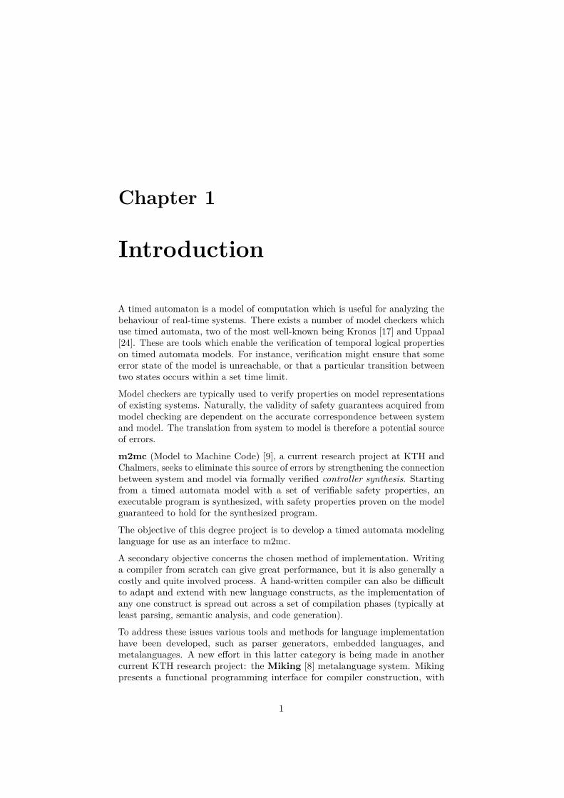
Chapter 1
Introduction
A timed automaton is a model of computation which is useful for analyzing thebehaviour of real-time systems. There exists a number of model checkers whichuse timed automata, two of the most well-known being Kronos [17] and Uppaal[24]. These are tools which enable the verification of temporal logical propertieson timed automata models. For instance, verification might ensure that someerror state of the model is unreachable, or that a particular transition betweentwo states occurs within a set time limit.
Model checkers are typically used to verify properties on model representationsof existing systems. Naturally, the validity of safety guarantees acquired frommodel checking are dependent on the accurate correspondence between systemand model. The translation from system to model is therefore a potential sourceof errors.
m2mc (Model to Machine Code) [9], a current research project at KTH andChalmers, seeks to eliminate this source of errors by strengthening the connectionbetween system and model via formally verified controller synthesis. Startingfrom a timed automata model with a set of verifiable safety properties, anexecutable program is synthesized, with safety properties proven on the modelguaranteed to hold for the synthesized program.
The objective of this degree project is to develop a timed automata modelinglanguage for use as an interface to m2mc.
A secondary objective concerns the chosen method of implementation. Writinga compiler from scratch can give great performance, but it is also generally acostly and quite involved process. A hand-written compiler can also be difficultto adapt and extend with new language constructs, as the implementation ofany one construct is spread out across a set of compilation phases (typically atleast parsing, semantic analysis, and code generation).
To address these issues various tools and methods for language implementationhave been developed, such as parser generators, embedded languages, andmetalanguages. A new effort in this latter category is being made in anothercurrent KTH research project: the Miking [8] metalanguage system. Mikingpresents a functional programming interface for compiler construction, with
1

extendability through the composition of smaller language fragments being a keyfeature.
In this degree project, the timed automata modeling language TML is designedas an interface to m2mc, and a compiler is implemented using Miking.
TML’s design is based on a study of three related projects: Uppaal, Kronos, andGraphviz Dot. Uppaal and Kronos form the basis for evaluation of TML.
1.1 Research Questions
The main motivation for this work is to design a good interface to m2mc. Asecondary motivation is to assess the usability of Miking as a tool for compilerconstruction.
TML is evaluated by a comparison with Uppaal and Kronos. We ask specificallywhether the modeling languages used in Uppaal and Kronos respectively can beimproved upon, and whether TML achieves any such improvement.
1.2 Scope
A complete interface for m2mc would need to support not only description oftimed automata models, but also the expression of safety requirements for modelchecking. To avoid too broad a scope TML is focused on description, leavingmodel checking to be considered as an extension.
1.3 Societal Impact
As reliance on software grows in all parts of society, software correctness becomesever more important. Serious adverse effects of malfunctioning software canrange from economic loss to threats against health and safety.
Formal methods like model checking and controller synthesis are importanttools for producing software with greater guarantees of correctness than what ispossible using conventional testing. Their use, however, is often time-consumingand requiring of a great deal of expert knowledge. To increase the viability offormal methods across a wider range of uses, better tools are needed. Accordingly,this work is focused on improving the usability of a controller synthesis tool.
Although the concrete consequences of the software developed in this project areultimately decided by its use, the general goal of supporting software correctnessis considered an ethical good.
2
1.4 Outline
The remainder of the thesis is organized as follows. In Chapter 2, we give somebackground on timed automata and compiler construction. Chapter 3 presentsthree existing modeling languages for timed automata. Chapter 4 describes theTML language, and some aspects of its design and implementation process. InChapter 5, TML is compared to Uppaal and Kronos by the modeling of twoexample systems. The results of this comparison are discussed in Chapter 6.Finally, in Chapter 7, we provide conclusions and present some potential futureimprovements of TML.
3

Chapter 2
Preliminaries
This chapter presents a background on timed automata, and their use in modelchecking and controller synthesis. Additionally, some standard concepts incompiler construction are presented.
2.1 Finite Automata
A finite automaton A is a model of computation consisting of locations connectedby edges. There is one initial location and one or more accepting locations. Asmall example is given in Fig. 2.1.
Each edge is labeled with a symbol from some alphabet Σ. An automaton reads asequence of symbols (i.e., a word) following at each point the edge correspondingto the symbol read. If automaton A after having read the entire word w ends upin an accepting location, we say that A accepts w. The set of all words acceptedby A is called the language L(A) of A.
a b
a
a b
Figure 2.1: An automaton for the language (a+b+)+.
In a non-deterministic finite automaton, a location may have multiple outgoingedges with the same symbol. Such an automaton accepts a word w if there existssome run of the automaton on w such that it ends in an accepting state.
4

2.2 Timed Automata
Timed automata [2] are an extension of finite automata, with the concept oftime represented as a finite set of real-valued clocks. Instead of recognizing alanguage of strings over some alphabet Σ, the language of a timed automaton isa set of timed words: pairs containing a symbol and a real-valued timestamp.Semantically, such a pair represents a symbol being read at a specific point intime.
Edges are extended with time constraints called edge guards, so that an edgemay be used only during some real-time interval. Additionally, each edge has anassociated set of clocks to be reset whenever the edge is traversed.
To this point we have described automata taking as input a predeterminedsequence of symbols. In the model checking context it is more natural to consideran automaton as a dynamic system with many possible behaviours. In this view,the language of an automaton corresponds to all possible system behaviours.Instead of symbols it is common to say actions and instead of a symbol beingread we say that an edge is fired and an action is performed.
2.2.1 Timed Safety Automata
In their original formulation [2], timed automata were derived from ω-automata,accepting or rejecting infinitely long timed words based on Büchi or Mulleracceptance conditions. These acceptance conditions are both based on theconcept of accepting states being visited infinitely often, which can be difficult toreason about. In particular, the implied conditions on surrounding non-acceptingstates are not always immediately obvious [5].
As an alternative formalism, timed safety automata (TSA) [15] adds locationinvariants to the timed automaton model. Location invariants, like edge guards,are simple conditions on clock values. For an automaton to enter or remainin a given location, the corresponding invariant must be satisfied. This addedmechanism replaces Büchi or Muller acceptance conditions,1 yielding a model ofequal expressivity but which is simpler to work with.
We next give a precise definition of the TSA model, following the presentationin [5].
Syntax
Let C be an alphabet of real-valued clocks, and Σ be an alphabet of actionsymbols. As a convention we use x, y, . . . as names for clock variables, anda, b, . . . for actions.
A clock constraint is a conjunctive formula of the form x ∗ n or x− y ∗ n, wheren ∈ N, x, y ∈ C, and ∗ ∈ {≤, <,=, >,≥}. Let B(C) denote the set of all clockconstraints.
1Formally, all states are Büchi accepting [15].
5
A timed automaton A is a tuple 〈N, l0, E, I〉 where
• N is a finite set of locations,• l0 ∈ N is the initial location,• E ∈ N ×B(C)× Σ× 2C ×N is the set of edges, and• I : N → B(C) defines an assignment of location invariants.
Location invariants are restricted to a downwards closed form with one clock,i.e., x ≤ n or x < n.
As a shorthand for edges, l g,a,r−→ l′ is read as equivalent to 〈l, g, a, r, l′〉 ∈ E.
Semantics
The semantics of timed safety automata are defined as a labeled transition systemwhere states are pairs 〈l, u〉 of locations and clock assignments. In an actiontransition, an edge is fired and the automaton moves to a new location. Thistransition is atomic. There are also delay transitions, representing a momentduring which the automaton stands still and allows time to pass.
In order to describe the transition system precisely some further definitions arerequired:
• A clock assignment u is a function C 7→ R+ i.e., an assignment of a realvalue to each clock in C. Let u ∈ g mean that with all clocks assignedaccording to u, the clock constraint g is satisfied.
• Addition u+d of a clock assignment u with a non-negative real d is definedas the result of adding d to each clock in C, i.e., for each x ∈ C, (u+d)(x) =u(x) + d.
• [r 7→ 0]u is the clock assignment u with a set of clocks r ⊆ C reset to zero,i.e., for all clocks x ∈ C,
([r 7→ 0]u)(x) ={
0 if x ∈ r,x otherwise.
Transitions are defined by the following rules:
• A delay transition 〈l, u〉 d→ 〈l, u+ d〉 for some non-negative real d exists ifu ∈ I(l) and (u+ d) ∈ I(l).
• An action transition 〈l, u〉 a→ 〈l′, u′〉 exists if l g,a,r−→ l′, u ∈ g, u′ = [r 7→ 0]u,and u′ ∈ I(l′).
Note that since time is continuous, there are an infinite number of delay andaction transitions.
6

2.2.2 Synchronizing Networks of Timed Automata
In modeling real-time systems it is often convenient to use several concurrentlyrunning automata. The TSA model does not define a way for automata tocommunicate, and this is thus left for individual software tools to design. Mostuse some type of special synchronization actions on edges to communicatebetween automata.
Note that adding communication does not increase the model’s strict expressivepower, as a network of communicating automata can be reduced to one automatonby a product construction.
2.3 Timed Automata Applications
This section gives an overview of how timed automata models are used in modelchecking and controller synthesis.
2.3.1 Model Checking
In considering the language of a timed automaton as a set of possible behavioursof some modeled real-time system, the purpose of model checking is generally toverify that some “good” behaviour is in this set, or that some “bad” behaviouris not.
Given a model of an elevator, for instance, you might want to verify that it cannever move while the doors are open (bad behaviour) or that it can reach floor19 within 30 seconds from any other floor (good behaviour).
A natural idea might be to express each such requirement r as a simple timedautomaton Vr. The system model automaton S could then be verified by checkingthat L(Vr) ⊆ L(S) for positive requirements, or that L(Vr) * L(S) for negativerequirements.
This is the language inclusion problem, which is decidable for standard fi-nite automata but unfortunately not for timed automata [2]. For this rea-son model checking requirements are instead usually expressed as formulas intimed computation tree logic (TCTL), the checking of which is decidable fortimed automata [1].
2.3.2 Controller Synthesis
Building on model checking, in controller synthesis we are not only interestedin verifying safety properties on a model, but also in producing an executablecontroller to uphold safety properties on a system running in an adversarialenvironment. To grasp the details, we will need some concepts and terminologyfrom the broader field of control theory.
7

Control Theory
Control theory concerns the study of systems which can be modeled in threediscrete parts: plant, controller, and environment [7].
A plant is assumed to operate in an environment, from which it receives inputswhich affect its state. The plant is modeled as a transition system (for ourpurposes, a timed automaton), with transitions defined for every possible inputfrom the environment.
In addition to the environment, the plant can also receive inputs from a controllersystem. The controller’s job is to monitor the state of the plant and steer itaccording to some control law.
Together, the plant and the controller form an autonomous system which reactsto environment changes.
As an example, we model an automatic climate control system as follows:
• Plant P : The state of a climate-controlled room, consisting of1. the temperature inside the room,2. a window which can either be open or closed, and3. a radiator which can either be running or not.
• Environment E: The world outside the room, which can affect the plantby changes in outside air temperature.
• Specification S: The temperature inside the room should always be between20 and 25 degrees Celsius.
• Control law L (enacted by Controller C): When the inside temperaturereaches above 24, open the window and turn off the radiator. When it fallsbelow 21, close the window and turn on the radiator.
• Actuator A: An electrical component which can toggle the state of thewindow and radiator. Used by C to affect the state of the plant.
The temperature inside the room is affected by three factors:
F1 The temperature outside.
F2 The state of the window.
F3 The state of the radiator.
F1 is outside the control of C. Such a factor is called a disturbance. F2 and F3are controlled by C (via the actuator A).
To enable modeling the plant, environment, and controller as three separateentities, the edges of the plant are marked as either uncontrollable or controllable.This defines which state changes can be induced by the environment vs. thecontroller, i.e., which inputs are disturbances and which are actuator signals [16].
8
The Controller Synthesis Problem
In control theory terms, assume that we can divide a real-time system modelinto environment E, plant P , and controller C. In order to model check thissystem, we need a complete understanding of the behaviour of all of its parts.This is called a closed system [16].
With C(E,P ) denoting a system consisting of plant P running in environment Eunder the influence of controller C, the model checking problem for a closedsystem can be phrased as:
Given an environment E, a plant P , a controller C, and some re-quirement φ, does C(E,P ) � φ hold?
In an open system we have an environment and a plant, but the controller isundefined. In this setting, the control problem is
Given E, P , and φ, is there a C such that C(S) � φ holds?
Finally, the controller synthesis problem is to produce a witness for a positiveanswer to the control problem, that is to produce the controller C such thatC(E,P ) � φ holds.
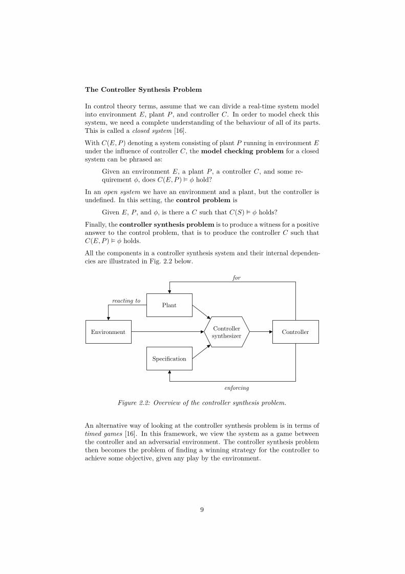
All the components in a controller synthesis system and their internal dependen-cies are illustrated in Fig. 2.2 below.
reacting toPlant
Specification
Controllersynthesizer
for
enforcing
ControllerEnvironment
Figure 2.2: Overview of the controller synthesis problem.
An alternative way of looking at the controller synthesis problem is in terms oftimed games [16]. In this framework, we view the system as a game betweenthe controller and an adversarial environment. The controller synthesis problemthen becomes the problem of finding a winning strategy for the controller toachieve some objective, given any play by the environment.
9

2.4 Compiler Construction
This section presents briefly some standard concepts used in compilerconstruction. A longer discussion is given to the topic of syntactic sugar, whichis important for the design and implementation of TML.
2.4.1 Compiler Phases
A compiler is a program which translates code in a source language to someother target language. Usually the source language adds a level of abstractionover the target language, with the intent of making it easier to write.
Due to their long-standing ubiquity in computing, the implementation of atypical compiler (including the TML compiler) can usually be described in termsof some well-established phases.
Starting from source code viewed as a sequence of characters, lexing is the processof dividing this sequence into discrete tokens. The resulting token sequence isvia parsing translated to an abstract syntax tree (AST), the branches of whichrepresents program statements and expressions.
Various semantic analysis and transformation operations may be performedon the AST. Commonly occurring are type checking, name analysis (in whiche.g., uses of variables are connected with their declarations), and optimization.Finally, the code generation phase uses the processed AST to produce output inthe given target language.
2.4.2 Syntactic Sugar
In defining the concrete syntax of a programming language, it is common tomake a distinction between core language features and syntactic sugar [23]. Thelargest part of the compiler – semantic analysis, AST transformations, andcode generation – operate on an abstract syntax tree consisting of constructsfrom the smaller core language. On top of the core language, syntactic sugar isadded to support new convenient syntax constructions which correspond moreor less directly to existing elements of the core language. In an early compilerphase (just after parsing) known as “desugaring,” statements in the full surfacelanguage are translated to the core language, i.e., the syntactic sugar is removed.This allows the addition of convenience features while leaving the majority ofthe compile chain unmodified, freeing the compiler from added complexity.
For a concrete example, we consider Miking’s implementation of tuples assyntactic sugar for records [20].
Records should be familiar to the reader (perhaps as “structs”) as a collection ofnamed fields:
{ age = 28, name = "Ernst" }
10

A tuple is a fixed-size ordered collection of (unnamed) values:
(28, "Ernst")
Tuples are implemented as syntactic sugar for records via a simple translation, inwhich element n of the tuple becomes a field with the name n. After desugaring,the above tuple (28, "Ernst") becomes record { 0 = 28, 1 = "Ernst" }.2Semantically, these two snippets of Miking code are completely equivalent.
Inherent to the concept of syntactic sugar is the introduction of slightly differingrepresentations of a program. After desugaring, the compiler’s view of a programis not the same as that of the user who wrote it. If not carefully considered, thissituation can lead to some trouble.
One complication which arises is in error messages and debugging. Withoutspecial consideration, errors detected during a later compiler phase such assemantic analysis (performed on a desugared abstract syntax tree) results inerror messages referencing the desugared program instead of that which the useractually typed. For example, if the first element of (28, "Ernst") is used in anincorrect type context, an error message might tell the user that field 0 has thewrong type.
The simplest solution to this issue is to make the correspondence between tuplesand records part of the language definition, and expect the user to be aware ofit. In this case no special action needs to be taken, but the cognitive burdenon the user is increased. The tuple feature becomes what is known as a leakyabstraction.
A better solution, and indeed one which is normally used, is to reconstruct theoriginal program from a desugared version, enabling the compiler to give errormessages referencing the program as written. This process is called resugaring.
To achieve this, the compiler must somehow remember the original programform – the information contained in the difference between (28, "Ernst") and{ 0 = 28, 1 = "Ernst" } cannot be fully discarded.
A quick solution in this particular case could be to disallow record field namesstarting with digits in the surface language. We would then know that anyrecord with field names beginning with 0− 9 was transformed from a tuple. Inmore complicated cases it can be necessary to store information for desugaringexplicitly.
2In Miking, record field names can consist of arbitrary strings. However, field names such as“0” which do not parse as identifiers must be escaped using the syntax #label"0". Accordingly,the actual syntax for this particular record is { #label"0" = 28, #label"1" = "Ernst" }.This detail is ignored for clarity in the main text.
11
2.5 Summary
A timed automaton is a model of computation useful for representing real-time systems. Timed automata can be used for model checking and controllersynthesis. The aim of model checking is to prove safety properties on a model.In controller synthesis, an executable program is produced to uphold safetyrequirements.
The mechanics of a compiler can generally be described as a sequence of phases.From a sequence of characters in some source language, and abstract syntax tree(AST) is produced. The AST is used to produce code in a target language. Acommonly used strategy for simplifying the implementation of compilers is totreat some language features as syntactic sugar. This strategy may be employedwherever there exists a close conceptual resemblance between two different syntaxconstructions.
12

Chapter 3
Related Work
This chapter presents a set of existing languages for constructing timed automatamodels. A study of these languages forms the context in which TML is created,influencing its design and feature set. Additionally, Uppaal and Kronos serve asthe basis for TML’s evaluation in Chapter 5.
The selection of Uppaal and Kronos for inclusion in this study is based on theirrelevance in the field, as indicated by [27], [6], and [19]. The third language,Graphviz Dot, is included even though it is not specifically related to timedautomata, as some of its features are used more or less directly in TML’s design.
off low bright
(a) Automaton L representing a lamp with two brightness settings.
(b) Automaton U representinga user of L.
Figure 3.1: A simple timed automata network N .
13

For illustration purposes an example system N from [4], illustrated in Fig. 3.1,is used throughout this section. In this figure, inter-automata communication ispictured using Uppaal’s version of synchronization actions (further explained inSec. 3.2.1), where input action press? synchronizes with output action press!.
Automaton L models a lamp with two brightness settings controlled using asingle button. When pressed twice in rapid succession, the highest brightnessmode is activated. U models a user who may press the button at any time.
3.1 Graphviz Dot
Graphviz [13] is a collection of programs which operate on general directed orundirected graphs. Most Graphviz programs produce some kind of visualization,but there are also tools in the collection which perform simple graph manipula-tions like extracting the connected components of a graph. A common modelinglanguage, Dot [14], is used across all Graphviz programs.
The lamp automaton L is modeled in Lsts. 3.1, 3.2 below. Note that the locationand edge properties used here are not chosen to be understood by Graphviz tools.The Dot language allows for arbitrarily named properties, leaving it to individualsoftware tools to assign semantic meaning to specific property names. The graphvisualization program dot, for instance, (part of the Graphviz program suite,not to be confused with the Dot language) looks for shape, label, and coloron location statements.
Listing 3.1: Dot implementation of automaton L from Fig. 3.1a.1 digraph lamp {2 off [initial = "true"];3 low;4 bright;56 off -> low [sync = "press?", reset="x"];7 low -> off [sync = "press?", guard="x >= 5"];8 low -> bright [sync = "press?", guard="x < 5"];9 bright -> off [sync = "press?"];10 }
Listing 3.2: Dot implementation of automaton U from Fig. 3.1b.digraph user {
idle [initial = "true"];idle -> idle [sync = "press!"];
}
A Dot program represents a directed or undirected graph, as determined by thedigraph (vs. graph) keyword on line 1 of Lsts. 3.1, 3.2. The program consistsof a sequence of declarations of locations and edges, each with an optional setof associated properties. This type of statement is recurrent in graph modeling
14

languages (including TML), so we introduce some precise terminology adaptedfrom the CSS language [10].
Location statement :Location selector︷︸︸︷
off
Declaration block︷ ︸︸ ︷[ initial︸ ︷︷ ︸
Property
= "true"︸ ︷︷ ︸Value︸ ︷︷ ︸
Declaration
]
Edge statement :
Edge selector︷ ︸︸ ︷off -> low
Declaration block︷ ︸︸ ︷[ action︸ ︷︷ ︸
Property
= "press?"︸ ︷︷ ︸Value︸ ︷︷ ︸
Declaration
, reset︸ ︷︷ ︸Property
= "y"︸︷︷︸Value︸ ︷︷ ︸
Declaration
]
Semantically, a location statement in Dot will either create a new location (ifnone exists using the given identifier), or it will modify an existing location’sproperties. An edge statement always creates a new edge, as multiple edges canexist between the same two locations.
We next give brief descriptions of two useful Dot language features, variants ofwhich are implemented in TML.
3.1.1 Default Properties and Subgraphs
When modeling many locations or edges which share the same properties, defaultproperties can be used either globally or locally within a delimited code block.Such a block is called a subgraph in Dot, though it is not strictly a subgraph – itmay for instance be composed exclusively of edge statements. The semantics ofdefault properties are exemplified in Lst. 3.3 below. The corresponding graph isillustrated in Fig. 3.2. Note that in Dot terminology locations are called “nodes,”which is reflected in the code.
a b d ec f
Figure 3.2: Graph produced by the program in Lst. 3.3.
15

Listing 3.3: Dot program illustrating the use of default properties.digraph example {
a;// Default applying to all subsequent nodesnode [shape = square];b;// Resetting the default shape to circlenode [shape = ""];subgraph {
c;// Applies to all subsequent nodes in the subgraphnode [shape = diamond];d;// Overriding a default with a local propertye [shape = parallelogram];
}f;
}
3.1.2 Edge Selector Shorthands
Subgraphs can be used in edge selectors to conveniently create multiple edges atonce: { a, b } -> { c, d } produces the graph below.
a b
c d
Figure 3.3: A graph defined by use of subgraphs in edge selectors.
An edge selector may also contain more than two endpoints, taking the form ofa longer chain. Each point in the chain may consist of either a single locationor a subgraph: { a, b } -> c -> { d, e } produces the graph in Fig. 3.4.Properties defined on such a chain selector applies to each generated edge.
16
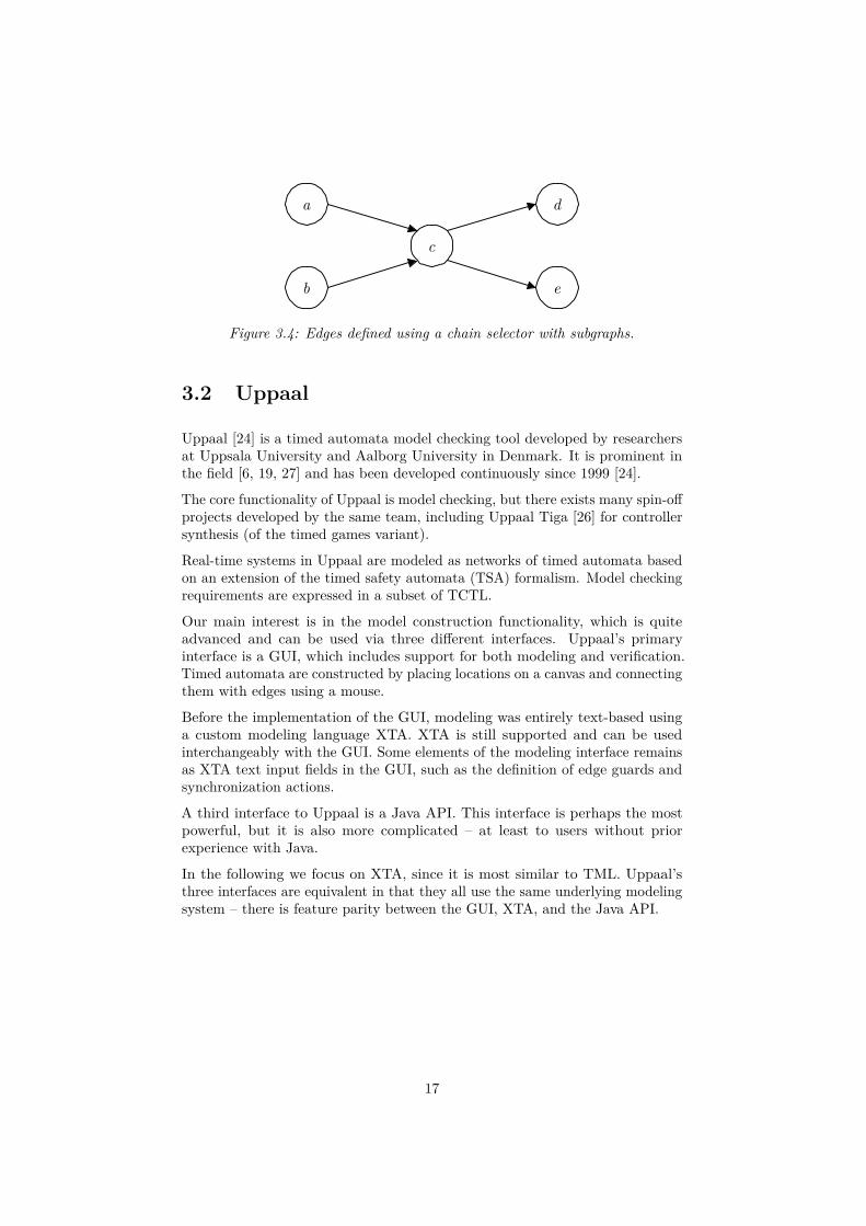
a
b
c
d
e
Figure 3.4: Edges defined using a chain selector with subgraphs.
3.2 Uppaal
Uppaal [24] is a timed automata model checking tool developed by researchersat Uppsala University and Aalborg University in Denmark. It is prominent inthe field [6, 19, 27] and has been developed continuously since 1999 [24].
The core functionality of Uppaal is model checking, but there exists many spin-offprojects developed by the same team, including Uppaal Tiga [26] for controllersynthesis (of the timed games variant).
Real-time systems in Uppaal are modeled as networks of timed automata basedon an extension of the timed safety automata (TSA) formalism. Model checkingrequirements are expressed in a subset of TCTL.
Our main interest is in the model construction functionality, which is quiteadvanced and can be used via three different interfaces. Uppaal’s primaryinterface is a GUI, which includes support for both modeling and verification.Timed automata are constructed by placing locations on a canvas and connectingthem with edges using a mouse.
Before the implementation of the GUI, modeling was entirely text-based usinga custom modeling language XTA. XTA is still supported and can be usedinterchangeably with the GUI. Some elements of the modeling interface remainsas XTA text input fields in the GUI, such as the definition of edge guards andsynchronization actions.
A third interface to Uppaal is a Java API. This interface is perhaps the mostpowerful, but it is also more complicated – at least to users without priorexperience with Java.
In the following we focus on XTA, since it is most similar to TML. Uppaal’sthree interfaces are equivalent in that they all use the same underlying modelingsystem – there is feature parity between the GUI, XTA, and the Java API.
17
3.2.1 Modeling with Uppaal XTA
This section presents an overview of Uppaal’s timed automata modeling semanticsand the XTA syntax. The semantics are based on TSA, so e.g., location invariantsand edge guards should be assumed without explicit comment. The presentationis restricted to a subset of modeling features, with focus on what is relevant forthe remainder of the thesis.
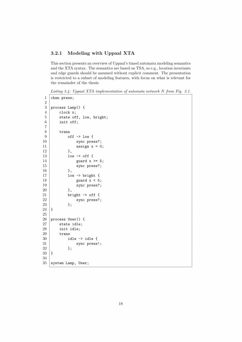
Listing 3.4: Uppaal XTA implementation of automata network N from Fig. 3.1.1 chan press;23 process Lamp() {4 clock x;5 state off, low, bright;6 init off;78 trans9 off -> low {10 sync press?;11 assign x = 0;12 },13 low -> off {14 guard x >= 5;15 sync press?;16 },17 low -> bright {18 guard x < 5;19 sync press?;20 },21 bright -> off {22 sync press?;23 };24 }2526 process User() {27 state idle;28 init idle;29 trans30 idle -> idle {31 sync press!;32 };33 }3435 system Lamp, User;
18
Templates
On a high level, automata in Uppaal are defined by templates, which are usedto create concrete automata processes. Lst. 3.4 contains definitions of twotemplates Lamp and User. The system definition on line 35 instantiates thesetemplates into processes.
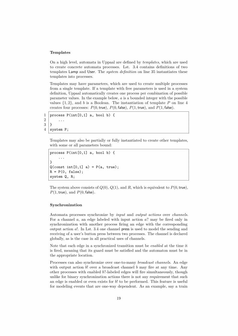
Templates may have parameters, which are used to create multiple processesfrom a single template. If a template with free parameters is used in a systemdefinition, Uppaal automatically creates one process per combination of possibleparameter values. In the example below, a is a bounded integer with the possiblevalues {1, 2}, and b is a Boolean. The instantiation of template P on line 4creates four processes: P (0, true), P (0, false), P (1, true), and P (1, false).
1 process P(int[0,1] a, bool b) {2 ...3 }4 system P;
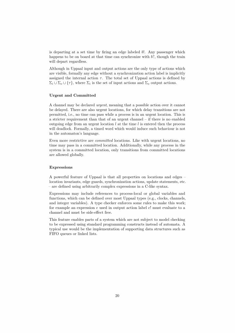
Templates may also be partially or fully instantiated to create other templates,with some or all parameters bound:
process P(int[0,1] a, bool b) {...
}Q(const int[0,1] a) = P(a, true);R = P(0, false);system Q, R;
The system above consists of Q(0), Q(1), and R, which is equivalent to P (0, true),P (1, true), and P (0, false).
Synchronization
Automata processes synchronize by input and output actions over channels.For a channel a, an edge labeled with input action a? may be fired only insynchronization with another process firing an edge with the correspondingoutput action a!. In Lst. 3.4 one channel press is used to model the sending andreceiving of a user’s button press between two processes. The channel is declaredglobally, as is the case in all practical uses of channels.
Note that each edge in a synchronized transition must be enabled at the time itis fired, meaning that its guard must be satisfied and the automaton must be inthe appropriate location.
Processes can also synchronize over one-to-many broadcast channels. An edgewith output action b! over a broadcast channel b may fire at any time. Anyother processes with enabled b?-labeled edges will fire simultaneously, thoughunlike for binary synchronization actions there is not any requirement that suchan edge is enabled or even exists for b! to be performed. This feature is usefulfor modeling events that are one-way dependent. As an example, say a train
19
is departing at a set time by firing an edge labeled b!. Any passenger whichhappens to be on board at that time can synchronize with b?, though the trainwill depart regardless.
Although in Uppaal input and output actions are the only type of actions whichare visible, formally any edge without a synchronization action label is implicitlyassigned the internal action τ . The total set of Uppaal actions is defined byΣi ∪ Σo ∪ {τ}, where Σi is the set of input actions and Σo output actions.
Urgent and Committed
A channel may be declared urgent, meaning that a possible action over it cannotbe delayed. There are also urgent locations, for which delay transitions are notpermitted, i.e., no time can pass while a process is in an urgent location. This isa stricter requirement than that of an urgent channel – if there is no enabledoutgoing edge from an urgent location l at the time l is entered then the processwill deadlock. Formally, a timed word which would induce such behaviour is notin the automaton’s language.
Even more restrictive are committed locations. Like with urgent locations, notime may pass in a committed location. Additionally, while any process in thesystem is in a committed location, only transitions from committed locationsare allowed globally.
Expressions
A powerful feature of Uppaal is that all properties on locations and edges –location invariants, edge guards, synchronization actions, update statements, etc.– are defined using arbitrarily complex expressions in a C-like syntax.
Expressions may include references to process-local or global variables andfunctions, which can be defined over most Uppaal types (e.g., clocks, channels,and integer variables). A type checker enforces some rules to make this work;for example an expression e used in output action label e! must evaluate to achannel and must be side-effect free.
This feature enables parts of a system which are not subject to model checkingto be expressed using standard programming constructs instead of automata. Atypical use would be the implementation of supporting data structures such asFIFO queues or linked lists.
20

3.3 Kronos
Another well-known model checker for timed automata is Kronos [28], developedat French research institute Verimag in the late 1990s [6]. The most recentrelease is from 2002 [17].
Kronos uses an automata model which is largely equivalent to TSA, except thatan edge may carry more than one action. Semantically, an edge firing triggersall its associated actions simultaneously.
Synchronization actions are used to model communication between automatain a network. Unlike in Uppaal, there is no distinction between input andoutput actions. An automaton which uses a synchronization action a is said tosynchronize on a. An edge labeled with a may fire only if every other automatonin the network which synchronizes on a simultaneously fires an a-labeled edge.Synchronization actions in Kronos can thus be used for either one-to-one ormany-to-many communication. The difference with Uppaal is meaningful whenmodeling simultaneous synchronization between three or more automata.
We note that this is the only means of communication between automata; i.e.,there are no shared clocks as exists in Uppaal. There are also no variables orfunctions, shared or otherwise.
Besides synchronization actions, internal actions are supported as well. Theyserve no mechanical purpose but can be used as a kind of symbolic annotation.
Listing 3.5: Kronos implementation of automaton L from Fig. 3.1a.#locs 3#trans 4#clocks x#sync press
loc: 0prop: init offinvar: TRUEtrans:TRUE => press; x := 0; goto 1
loc: 1prop: lowinvar: TRUEtrans:x >= 5 => press; ; goto 0x < 5 => press ; ; goto 2
loc: 2prop: brightinvar: TRUEtrans:TRUE => press; ; goto 0
21
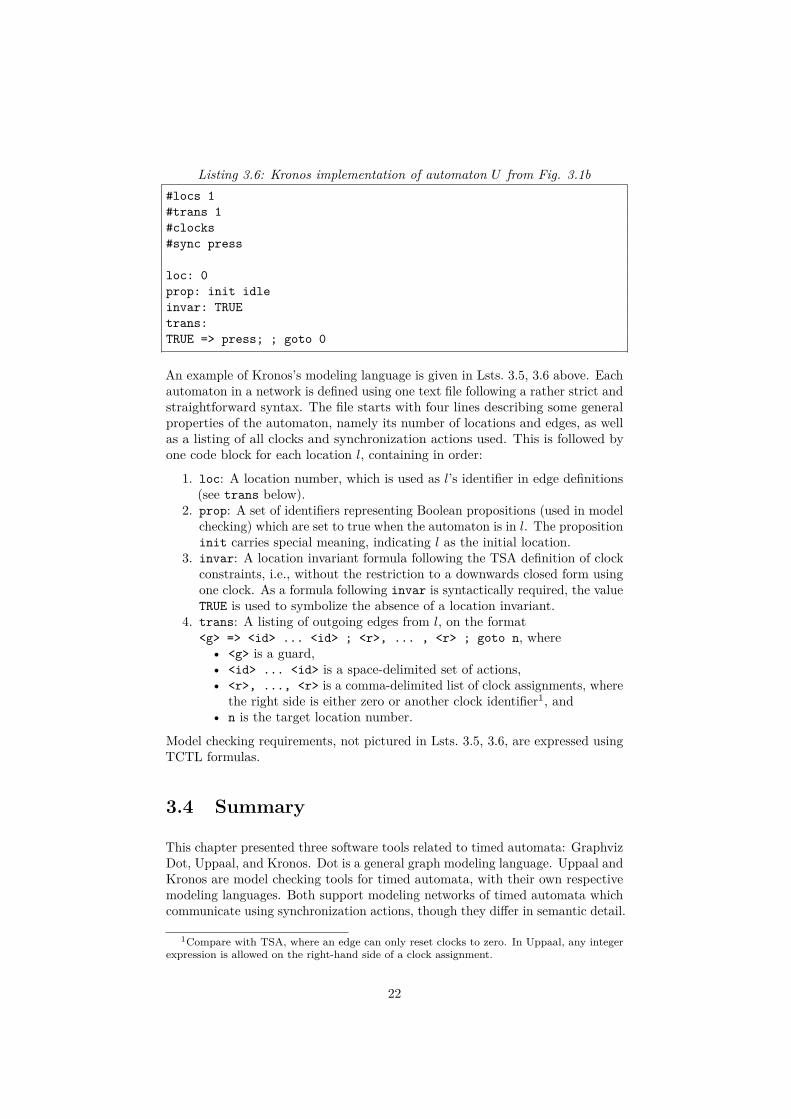
Listing 3.6: Kronos implementation of automaton U from Fig. 3.1b#locs 1#trans 1#clocks#sync press
loc: 0prop: init idleinvar: TRUEtrans:TRUE => press; ; goto 0
An example of Kronos’s modeling language is given in Lsts. 3.5, 3.6 above. Eachautomaton in a network is defined using one text file following a rather strict andstraightforward syntax. The file starts with four lines describing some generalproperties of the automaton, namely its number of locations and edges, as wellas a listing of all clocks and synchronization actions used. This is followed byone code block for each location l, containing in order:
1. loc: A location number, which is used as l’s identifier in edge definitions(see trans below).
2. prop: A set of identifiers representing Boolean propositions (used in modelchecking) which are set to true when the automaton is in l. The propositioninit carries special meaning, indicating l as the initial location.
3. invar: A location invariant formula following the TSA definition of clockconstraints, i.e., without the restriction to a downwards closed form usingone clock. As a formula following invar is syntactically required, the valueTRUE is used to symbolize the absence of a location invariant.
4. trans: A listing of outgoing edges from l, on the format<g> => <id> ... <id> ; <r>, ... , <r> ; goto n, where• <g> is a guard,• <id> ... <id> is a space-delimited set of actions,• <r>, ..., <r> is a comma-delimited list of clock assignments, where
the right side is either zero or another clock identifier1, and• n is the target location number.
Model checking requirements, not pictured in Lsts. 3.5, 3.6, are expressed usingTCTL formulas.
3.4 Summary
This chapter presented three software tools related to timed automata: GraphvizDot, Uppaal, and Kronos. Dot is a general graph modeling language. Uppaal andKronos are model checking tools for timed automata, with their own respectivemodeling languages. Both support modeling networks of timed automata whichcommunicate using synchronization actions, though they differ in semantic detail.
1Compare with TSA, where an edge can only reset clocks to zero. In Uppaal, any integerexpression is allowed on the right-hand side of a clock assignment.
22
Chapter 4
The TML Language
This chapter concerns the design and implementation of TML. In Sec. 4.1, someinitial challenges and resulting design choices are presented. The core TMLlanguage and some optional extension features are described in Sec. 4.2. Thefull syntax is given in Sec. 4.3. Sec. 4.4 gives some technical details on theimplemented compiler.
4.1 Design Challenges
With m2mc still in early development, developing a modeling language to fit itsneeds comes with some challenges related to underspecification, both in designand in technical details.
C1 Like Uppaal and Kronos, m2mc is being developed with the TSA modelof timed automata as a formal foundation. Beyond this, there is not yeta complete definition of its intended feature set. Some mechanism forcommunication, for example, is likely be considered at some point, thoughthis addition is not certain nor is it determined how such a feature wouldwork semantically.
C2 The technical framework around m2mc is also liable to change, i.e., theprogramming language used in its implementation. Current work is beingmade in the Coq proof assistant, but this will likely change later on indevelopment. Taking this into consideration, TML must be possible tointegrate in as wide as possible a selection of potential technical frameworks.
Intermediate Representation
Ideally, this degree project would include integration of TML into the largerm2mc system, by compilation of TML source code all the way to a timedautomata representation internal to m2mc. Unfortunately this is not practicalgiven the early development stage of m2mc (challenge C2).
23
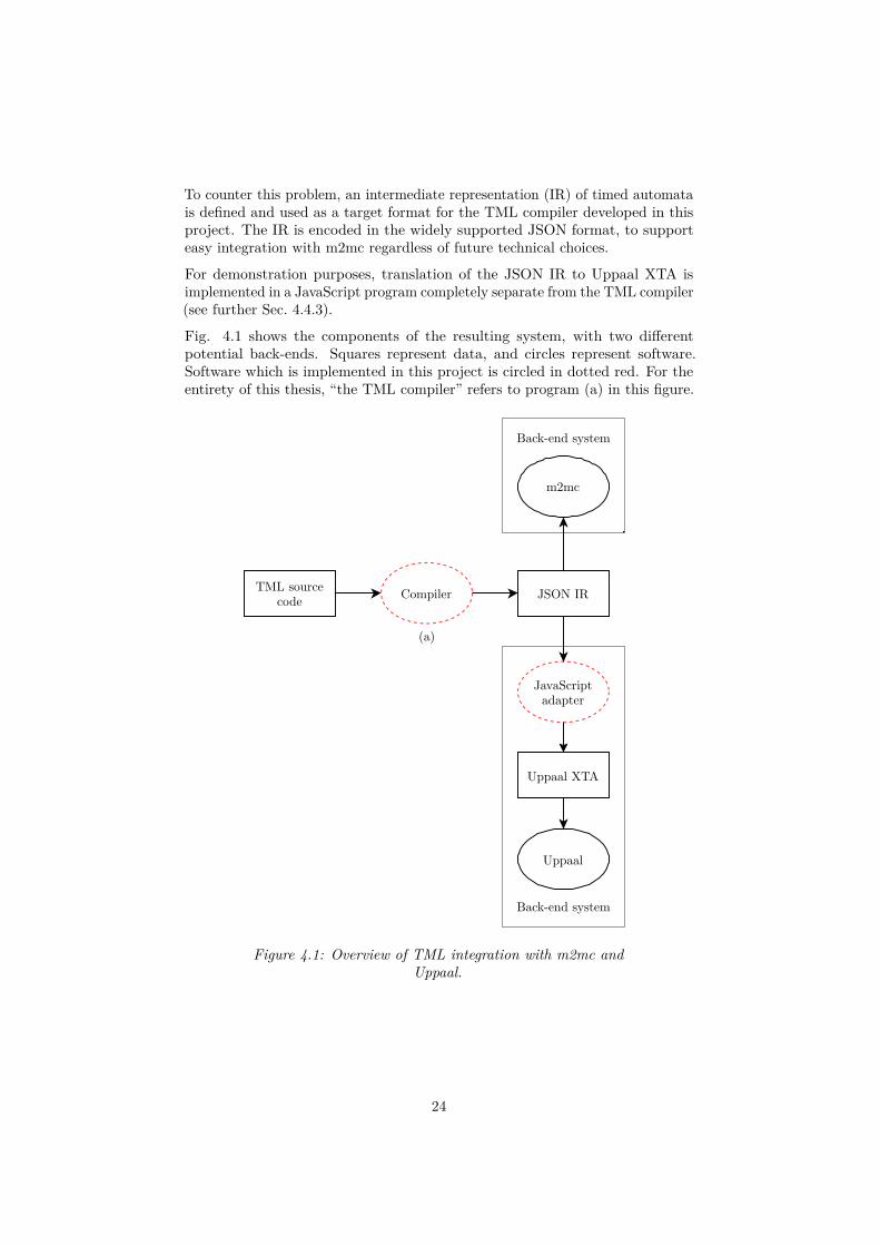
To counter this problem, an intermediate representation (IR) of timed automatais defined and used as a target format for the TML compiler developed in thisproject. The IR is encoded in the widely supported JSON format, to supporteasy integration with m2mc regardless of future technical choices.
For demonstration purposes, translation of the JSON IR to Uppaal XTA isimplemented in a JavaScript program completely separate from the TML compiler(see further Sec. 4.4.3).
Fig. 4.1 shows the components of the resulting system, with two differentpotential back-ends. Squares represent data, and circles represent software.Software which is implemented in this project is circled in dotted red. For theentirety of this thesis, “the TML compiler” refers to program (a) in this figure.
Compiler JSON IRTML source
code
JavaScriptadapter
Uppaal XTA
Uppaal
m2mc
(a)
Back-end system
Back-end system
Figure 4.1: Overview of TML integration with m2mc andUppaal.
24

Shallow vs. Deep Features
To address challenge C1, we define a distinction between shallow and deeplanguage features.
Shallow features are considered fully compatible with the basic TSA model oftimed automata. A shallow feature is either directly a part of the TSA model,or it can be implemented as light syntactic sugar on top of it.
Deep features are dynamic in nature, and cannot cleanly be statically resolvedto fit TSA. They thus require extension of the JSON IR and explicit supportfrom any back-end system using it. A deep feature we have seen in Sec. 3 whichis present in most timed automata tools is support for networks of automata viainter-automaton communication, using e.g., synchronization actions or sharedinteger variables.
To make the distinction more precise, we consider as “deep” any syntactic sugarfeature which creates a need for extensive resugaring in the back-end system.For example, inter-automata communication could be implemented as syntacticsugar on top of TSA using a product construction, but the distance betweensource model and desugared TSA model is determined too large to make this apractical choice.
In fact, resugaring is not considered at all in this project, so all shallow featuresmust work well without any resugaring. This imposes the requirement thatsemantic errors in syntactic sugar constructs must be caught by the TMLcompiler, and not carried through to a back-end system.
Since m2mc has not committed to supporting any feature outside the bounds ofTSA, a decision is made to focus on shallow features. The deep features whichare added are done so on a hypothesis of what might be useful to m2mc inthe future. Deep features are implemented with clear separation from the corelanguage, in a way which makes them easy to enable or disable.
4.2 Design
This section presents an overview of the TML language. First, the generalstructure of a TML program is explained, after which follows a detailed listingof shallow and deep features. The exact syntax of TML presented in Sec. 4.3.
As a starting example, LT (Fig. 4.2) is implemented in Lst. 4.1 below. LT is thelamp automaton L from Sec. 3 modeled without synchronization.
25

off low bright
Figure 4.2: Automaton LT representing a lamp with two brightness settings.
Listing 4.1: TML implementation of automaton LT from Fig. 4.2.init offlowbright
off -> lowaction { press }reset { x }
low -> offguard { x >= 5 }action { press }
low -> brightguard { x < 5 }action { press }
bright -> offaction { press }
Reusing the terminology introduced in Sec. 3.1, each TML statement consists ofa location or edge selector followed by an optional declaration block. Locationshave one possible property: invar (invariant). Edges have three: guard, action,and reset. Their correspondence to definitions in the TSA model should beobvious.
An edge or location statement’s declaration block may have at most one of eachproperty. An automaton must have exactly one initial location, marked usingthe init keyword.
In a program consisting of statements s1, s2, . . . , sn, multiple statements mayreference the same location or edge. Each edge statement creates a new edge,while repeated location statements modify an existing location. For each such
26

pair of location statements sx, sy where x < y, declarations in sy have precedenceover properties declared in sx.
We can note that the location statements low and bright in Lst. 4.1 do notcarry any additional information and may be removed. The existence of theselocations will be inferred from their appearance in edge statements.
TML is not whitespace-sensitive; indentation is used for readability.
4.2.1 Shallow Features
The following shallow features are fully implemented in the TML compiler,evaluating to standard TSA.
Default Statements
Default properties for locations and edges are implemented following their designin Dot (Sec. 3.1.1), with a location or edge default applying to all statementsfollowing its definition.
Default properties may be overridden or cleared locally on a single location oredge statement. A subsequent default statement may also modify or void anexisting default property. TML does not have any feature corresponding toDot’s subgraphs, so this voiding mechanism is used for applying defaults to adelimited code block.
Lst. 4.2 below illustrates the details of default statements. On line 2 a defaultinvariant is defined applying to all subsequent location statements. On line 4 thedefault is overridden with a locally defined invariant on location c. The defaultis cleared using !, locally for one location e on line 6, and for all subsequentlocations (i.e., f) on line 7. The resulting model’s location invariants are shownin Tbl. 4.1.
Listing 4.2: Example TML program illustrating the use of default properties.1 init a2 default location invar { x < 1 }3 b4 c invar { x < 2 }5 d6 e invar!7 default location invar!8 f
27

Table 4.1: Result of program in Lst. 4.2 .
Location Invariant
a noneb x < 1c x < 2d x < 1e nonef none
Selector Shorthands
Mirroring edge selector shorthands in Dot (Sec. 3.1.2), TML lets the user declareseveral edges at once using edge chains:
[a, b] -> c -> [d, e]
Each link in the chain is either a location or a location group, consisting simplyof a bracketed list of location identifiers. Like in Dot, properties defined on thisselector applies to each generated edge.
Location groups can also be used in location selectors, as a light-weight alternativeto defaults:
[a, b]guard { x < 5 }
In Dot the equivalent would be achieved using a location default contained in asubgraph:
subgraph {node [guard = "x < 5"];a; b;
}
4.2.2 Deep Features
The following features are not evaluated by the TML compiler, but insteadcarried over in their original form to the intermediate JSON representation.Thus their exact semantics are decided by the back-end system. These featuresare considered optional extensions to the TML language, usable in separatelanguage variants (see further Sec. 4.4.2).
28

Synchronization Actions
The syntax of synchronization actions in TML coincide with Uppaal’s input/out-put actions; i.e., for a channel c, c! is an output action and c? is an input action.Broadcast and urgent channels are not supported.
A network of n automata is modeled using n individual TML files, each describingone automaton. These are compiled separately to n JSON IR files.
Controller Synthesis
To support controller synthesis applications, a TML extension is defined whichallows the distinction between controllable and uncontrollable edges. In the viewof a system as divided into plant, environment, and controller, this determineswhich plant transitions are induced by the environment vs. the controller.
The syntax a -> b is used for controllable edges, and a >> b for uncontrollableedges. This mirrors the implementation in Uppaal Tiga, though Tiga uses thesyntax a -u-> b for uncontrollable edges. Both types of edges can be usedinterchangeably within an edge chain.
4.3 Syntax
Due to design challenge C1, the TML compiler is designed to work with a setof syntax variations. Each language variant consists of a common core syntaxjoined with some set of deep features.
In particular, the compiler supports four language variants:
V1: TML-TSA. This is the base language variant, which is fully compatiblewith TSA. It includes all shallow features of TML.
V2: TML-SYNC. This variant is equivalent to TML-TSA, but with theaddition of synchronization actions. For compatibility with Uppaal, in thisvariant actions are used exclusively for communication, i.e., all actions areeither input or output actions.
V3: TML-CTRL. TML-TSA with the controller synthesis feature describedin Sec. 4.2.2.
V4: TML-CTRL-SYNC. This is the union of TML-SYNC and TML-CTRL,supporting both synchronization actions and controllable/uncontrollableedges.
The syntax of TML-TSA is listed in an extended Backus-Naur format (BNF) inLst. 4.3. The starting symbol for the grammar is Program. A precise definitionof the BNF format used is given in W3C’s XML specification [12].
29

The grammar allows for some semantically incorrect TML programs. We thusadd the following validity constraints:
R1 There must be exactly one initial location.
R2 Each statement must have at most one of each type of property.
Listing 4.3: The complete syntax of TML-TSA.Program ::= statement*
statement ::= location | edge | default
location ::= "init"? locationSelector locationProperty*edge ::= locationSelector ("->" locationSelector)+
edgeProperty*default ::= locationDefault | edgeDefault
locationSelector ::= id | "[" id ("," id)* "]"
locationDefault ::= "default" "location" locationProperty*edgeDefault ::= "default" "edge" edgeProperty*
locationProperty ::= invaredgeProperty ::= guard | action | reset
invar ::= "invar" ("!" | "{" invarExpr "}")guard ::= "guard" ("!" | "{" guardExpr "}")action ::= "action" ("!" | "{" id "}")reset ::= "reset" ("!" | "{" clocks "}")
invarExpr ::= invarConjunct ("&" invarConjunct)*invarConjunct ::= id ("<=" | "<") nat
guardExpr ::= guardConjunct ("&" guardConjunct)*guardConjunct ::= (id op nat) | (id "-" id op nat)op ::= "<=" | "<" | "==" | ">" | ">="
clocks ::= id ("," id)*
id ::= (letter | "_") (letter | "_" | digit)*letter ::= [a-zA-Z]digit ::= [0-9]nat ::= [1-9] digit*
Syntax variations in TML-SYNC and TML-CTRL are easily defined by thereplacement of rules.
In TML-SYNC, the rule for action uses the keyword sync and requires ! or ?to follow a channel identifier:
action ::= "sync" ("!" | "{" id ("!" | "?") "}")
30

TML-CTRL extends the rule for edge to allow for uncontrollable edges:
edge ::= locationSelector (("->" | ">>") locationSelector)+edgeProperty*
Finally, TML-CTRL-SYNC is defined by Lst. 4.3 with both of these rule replace-ments.
As a consequence of the differing feature sets, each language variant also compilesto a distinct IR format. The details are given in Appendix A.
4.4 Implementation
The TML compiler1 is written entirely in MCore [20], a metalanguage designedspecifically for use in the Miking project. MCore is a minimal language, intendedin the long term to be used primarily as an intermediate language. Thismulti-level approach is intended to enable the creation of multiple higher-levelmetalanguages, specializing in the implementation of different types of objectlanguages. The Miking project is currently in pre-release development, so muchof the system is liable to change after the writing of this thesis.
As an evaluation of the Miking system, the results from this project are ultimatelydeemed inconclusive. In order to make definitive judgements about the system inits current form, more time would be needed both for a deeper study of Mikingand to establish a framework for comparison with other compiler implementationmethods.
4.4.1 Compiler Phases
Compilation of a TML model to JSON IR is implemented in five distinct phases:
P1 Parsing
P2 Semantic analysis
P3 AST transformation
P4 Evaluation
P5 Code generation
TML’s parser is constructed using a standard library of parser combinatorfunctions included in the Miking distribution. The parser creates an abstractsyntax tree which is structurally very similar to the BNF representation ofTML’s syntax (Lst. 4.3). Each node below the root of this tree represents aTML statement, i.e., a location, edge, or default statement.
In phase P2, the AST is checked for violations of validity constraints to catcherrors in programs which are syntactically correct but semantically ill-formed.
1The TML compiler is avaliable online at https://github.com/ernstwi/tml. A snapshotof the repository as of 2021/02/26 is embedded in this PDF as an attachment tml.zip.
31

For example, even though any location statement may be preceded by the initkeyword, by validity constraint R1 a TML program must contain exactly oneinitial location.
After semantic checks have passed, the AST is transformed to a form which iseasier to work with for the following evaluation step. Evaluation is the processof producing an actual timed automata model from the AST representation of aprogram, through interpretation of location, edge, and default statements.
Finally, this timed automaton model is converted to its intermediate text-basedrepresentation using a set of JSON functions from the Miking standard library.
4.4.2 Language Variants
The motivation for using a discrete syntax for each language variant, over simplyexpanding a single common syntax, is twofold. Firstly, the chosen approachallows for greater freedom in designing the syntax of individual language variants,as a syntax construction in variant A does not need to agree with those in B.
Secondly, using distinct syntaxes lets the compiler catch compatibility errors asearly as possible. For instance, in the TML-TSA language variant synchronizationactions do not exist, so sync { a! } is recognized immediately as a syntax error.If a shared syntax was used, compatibility errors like this would need to beconsidered explicitly in the semantic analysis phase.
To implement TML language variants, Miking’s concept of language fragmentswas used. In this framework, a language fragment is defined as a collection ofrelated data types (generally representing AST nodes) and functions over these.Language fragments are composable, allowing for the definition of a single datatype or function to be constructed from multiple merged fragments.
This design is aimed at supporting the construction of extendable compilers, en-couraging the implementation of languages in a modular manner as compositionsof smaller language fragments.
For the TML compiler, individual language fragments are used for each syntacticelement which differs between language variants. For example, two fragmentsare used to define the different versions of edge actions used in TML-TSA andTML-SYNC. To form complete compilers, these small language fragments arecomposed with a larger base fragment implementing a general AST used acrossall TML variants.
4.4.3 Uppaal XTA Adapter
This extension of the TML compiler translates a set of intermediate representationfiles produced from the TML-SYNC language variant to a model in Uppaal’sXTA format. TML-SYNC is used as all its features are compatible with Uppaal.
The adapter program is written separately and in a different programminglanguage to demonstrate the intended use of the IR format, which can betrivially parsed in any programming language with JSON support.
32

Listing 4.4: Adapter program ir-to-xta is used to translate TML-SYNC IR toUppaal XTA.#!/usr/bin/env node
// This program reads TML-SYNC IR and outputs Uppaal XTA.// Usage: ./ir-to-xta <IR-1> <IR-2> ... <IR-n>
let fs = require('fs');
let files = process.argv.splice(2);let irs = files.map(f => JSON.parse(fs.readFileSync(f)));let channels = new Set();irs.forEach(ir => ir.channels.forEach(c => channels.add(c)));files.forEach((f, i) => irs[i].name = f.replace(/\.[^\.]*$/, ''));
print(0, `chan ${[...channels].join(', ')};`);newline();
irs.forEach(ir => {print(0, `process ${ir.name}() {`);
if (ir.clocks.length > 0) {print(4, `clock ${ir.clocks.join(', ')};`);newline();
}print(4, 'state');
ir.locations.forEach(l => {write(8, l.id + (l.invariant == null ? '' : ` { ${l.invariant} }`));if (last(ir.locations, l))
print(0, ';')else
print(0, ',')});newline();
print(4, `init ${ir.locations.filter(l => l.initial == true)[0].id};`);newline();
if (ir.edges.length > 0) {print(4, 'trans');
ir.edges.forEach(e => {print(8, `${e.from} -> ${e.to} {`);if (e.guard != null)
print(12, `guard ${e.guard};`);if (e.sync != null)
print(12, `sync ${e.sync.id}${e.sync.type == 'input' ? '?' :'!'};`);
if (e.reset != null)print(12, `assign ${e.reset.map(c => `${c} := 0`).join(', ')};`);
if (last(ir.edges, e))print(8, '};');
else
33

print(8, '},');});
}print(0, '}');newline();
});
print(0, `system ${irs.map(ir => ir.name).join(', ')};`);
function print(indent, string) {console.log(' '.repeat(indent) + string);
}
function write(indent, string) {process.stdout.write(' '.repeat(indent) + string);
}
function last(array, element) {if (array.indexOf(element) == array.length - 1)
return true;return false;
}
function newline() {process.stdout.write('\n');
}
4.5 Summary
To address issues of underspecification, TML is designed with a set of optionalextensions building on a shared core syntax. Default statements and selectorshorthands are two features which are adopted from Graphviz Dot.
A compiler for TML is implemented, targeting an intermediate JSON representa-tion of timed automata. As a demonstrative use of this IR in a back-end system,a separate program is presented which translates the IR to Uppaal XTA.
34

Chapter 5
Evaluation
As a basis for evaluation of TML, two example systems are modeled in TML,Kronos, and Uppaal XTA.
The chosen example systems are Fischer’s mutual exclusion protocol andCSMA/CD. Both are protocols from the parallel computing field. Due totheir frequent use as benchmarking examples for model checking tools [19],implementations of these protocols are available from authors directly associatedwith Uppaal and Kronos respectively. The evaluation is based on these existingimplementations where possible.
Each protocol is given its own section, wherein the protocol is first explained,after which implementations are presented. Each section is concluded with abrief qualitative assessment of the different implementations’ relative merits.
As an aside from the main evaluation, Sec. 5.4 presents an additional XTA modelof Fischer’s protocol, generated by the TML compiler.
5.1 Method
Prior to performing the evaluation, some conclusions about Kronos and Up-paal XTA were drawn from their examination in chapter 3 which affected theformulation of the core research question.
Kronos’ modeling language is very sparse. Some seemingly obvious opportunitiesfor improvement of the user experience are left unimplemented. For example,the number of locations and edges used could easily be inferred from a programinstead of requiring this information to be listed in a file header. This leads usto believe that the design of the modeling language itself was likely not a highpriority in the Kronos project.
Uppaal on the other hand is highly developed in terms of language features,to a degree which would be difficult to match for any project on the scale of aMaster’s thesis project.
35

With this in mind, for an evaluation focused on overall language quality andcapabilities, the results seem predetermined.
A choice was thus made to put the question of “Which is best?” aside and focusinstead on individual language features. In this more granular view, we considerfor both of the studied protocols simply which language features were useful,across all three modeling languages.
The aim of this approach is to reveal firstly whether there is anything new andworthwhile in TML as compared with Uppaal and Kronos, and secondly whetherthere are specific features from Uppaal or Kronos which might be beneficial asfuture additions to TML.
5.2 Fischer’s Mutual Exclusion Protocol
The purpose of a mutual exclusion protocol is to protect access to some sharedresource among n concurrent processes, such that the resource is only accessedby one process at a time. Access to the shared resource is wrapped in a block ofcode designated as a critical section. A mutual exclusion protocol guaranteesthat only one process at a time is in such a critical section.
This is commonly achieved using some type of locking mechanism. In thisterminology, a shared lock is held by at most one process at any point in time.Only the process holding the lock may enter its critical section, and it can notrelease the lock before the critical section is exited.
Fischer’s mutual exclusion protocol [18] uses one shared (atomic) variable id asa lock, shared between n processes p1, p2, . . . , pn.
The protocol is described in pseudocode in Lst. 5.1. When process pi wants toenter its critical section, it waits until the lock is free (id = 0) and then (after amaximum delay l) requests the lock by setting id := i. pi then waits a minimumduration k and checks if id is still i. If this is true then pi enters the criticalsection, after the conclusion of which it releases the lock by resetting id to 0. Ifit is false, this means that between line 1 and 4 of process pi, some other processpj read id = 0 and requested the lock by setting id := j. In this case pi will waituntil the lock is released, and then try again.
Listing 5.1: Fischer’s mutual exclusion protocol for process i.1 wait until id == 02 id := i3 wait k4 if id == i5 execute critical section6 id := 07 else8 go to line 1
In the following implementations, we consider Fischer’s mutual exclusion protocolfor two processes.
36

5.2.1 Uppaal XTA
The Uppaal XTA implementation presented here is based on a model includedas an example with the most recent Uppaal distribution.[25] Automaton PU
i inFig. 5.1 describes the behaviour of process pi.
The location req corresponds to the point between line 1 and 2 of Lst. 5.1, whereid has been read but not yet written. The location invariant x ≤ l ensures thatthe automaton stays in this location for at most l time units, which togetherwith the minimum delay k in location wait (enforced by guards on the outgoingedges) is important for the protocol’s correctness.
id = 0
x := 0start
x := 0
id := i
reqx ≤ l
x > k
id = iwait
id := 0
cs
Figure 5.1: Timed automaton PUi describing the behaviour of process pi in
Fischer’s mutual exclusion protocol.
For the XTA representation of PUi , see Lst. 5.2. Note that the template P is
instantiated on line 37 without a parameter i. As described in Sec. 3.2.1, Uppaalwill automatically create one process from the template with each possible freeparameter value. In this case, since we are using a custom type id_t which isan integer ranging over [1, 2], two processes are created.
Listing 5.2: Uppaal XTA implementation of Fischer’s mutual exclusion protocolwith two processes.
1 typedef int[1,2] id_t;2 int id;34 process P(const id_t i) {5 clock x;6 const int k = 10;7 const int l = 5;89 state10 wait,11 req { x<=l },12 start,13 cs;
37
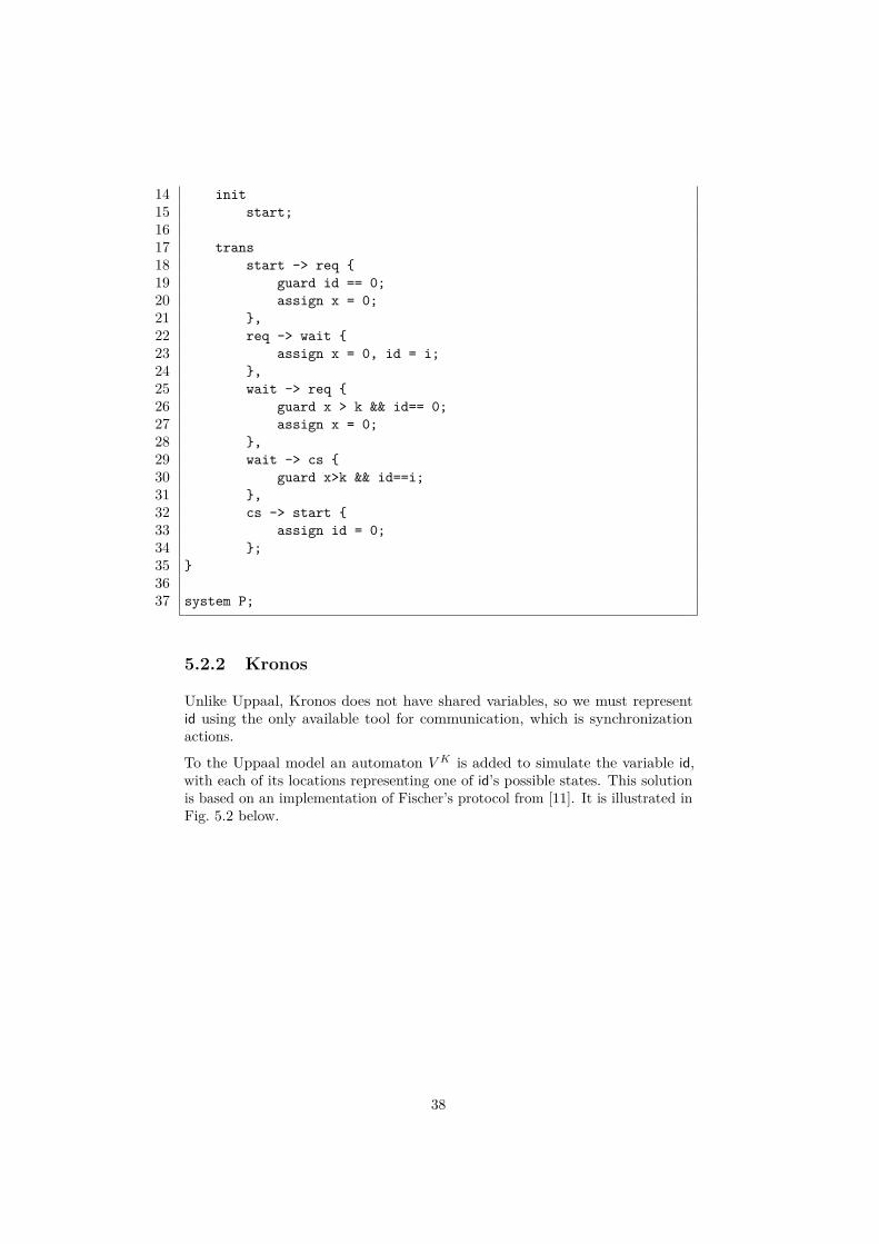
14 init15 start;1617 trans18 start -> req {19 guard id == 0;20 assign x = 0;21 },22 req -> wait {23 assign x = 0, id = i;24 },25 wait -> req {26 guard x > k && id== 0;27 assign x = 0;28 },29 wait -> cs {30 guard x>k && id==i;31 },32 cs -> start {33 assign id = 0;34 };35 }3637 system P;
5.2.2 Kronos
Unlike Uppaal, Kronos does not have shared variables, so we must representid using the only available tool for communication, which is synchronizationactions.
To the Uppaal model an automaton V K is added to simulate the variable id,with each of its locations representing one of id’s possible states. This solutionis based on an implementation of Fischer’s protocol from [11]. It is illustrated inFig. 5.2 below.
38

tryix := 0
start
setIdix := 0
reqx ≤ l
enteri x > k
tryix > k
x := 0
wait
resetIdi
cs
(a) Automaton P Ki representing process pi.
setId2
setId1
zero
resetId2
setId1
two
setId2
resetId1
one
enter1
setId1 setId2
enter2
try1 try2
(b) Automaton V K representing the variable id.
Figure 5.2: Kronos model of Fischer’s mutual exclusion protocol.
PK1 and V K are implemented in Lsts. 5.3, 5.4. Note that we do not have integer
constants, so k = 5 and l = 10 are hard coded. The implementation of PK2 is
omitted – it is identical with PK1 except for its process identifier.
It should also be noted that technically all automata in a Kronos network sharenamespaces for locations and clocks, so in reality the location start of PK
1 shouldbe named start1, etc. We choose here to ignore this detail.
39
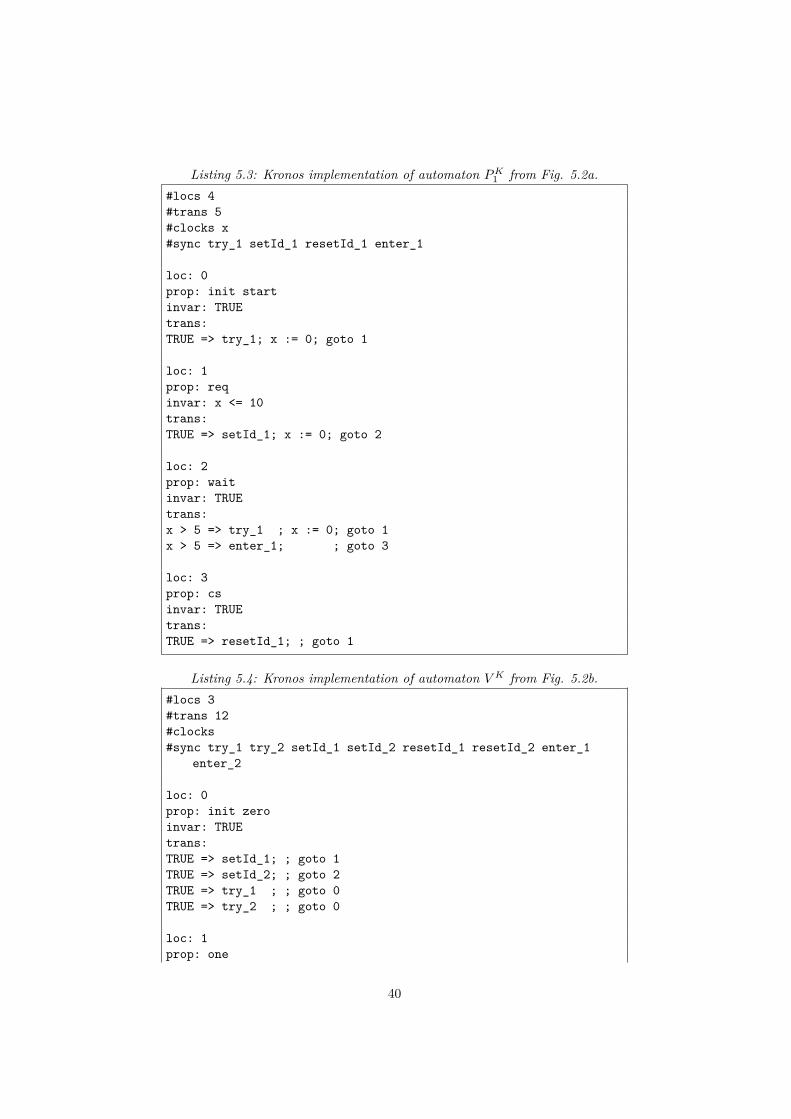
Listing 5.3: Kronos implementation of automaton PK1 from Fig. 5.2a.
#locs 4#trans 5#clocks x#sync try_1 setId_1 resetId_1 enter_1
loc: 0prop: init startinvar: TRUEtrans:TRUE => try_1; x := 0; goto 1
loc: 1prop: reqinvar: x <= 10trans:TRUE => setId_1; x := 0; goto 2
loc: 2prop: waitinvar: TRUEtrans:x > 5 => try_1 ; x := 0; goto 1x > 5 => enter_1; ; goto 3
loc: 3prop: csinvar: TRUEtrans:TRUE => resetId_1; ; goto 1
Listing 5.4: Kronos implementation of automaton V K from Fig. 5.2b.#locs 3#trans 12#clocks#sync try_1 try_2 setId_1 setId_2 resetId_1 resetId_2 enter_1
enter_2
loc: 0prop: init zeroinvar: TRUEtrans:TRUE => setId_1; ; goto 1TRUE => setId_2; ; goto 2TRUE => try_1 ; ; goto 0TRUE => try_2 ; ; goto 0
loc: 1prop: one
40
invar: TRUEtrans:TRUE => enter_1 ; ; goto 1TRUE => setId_1 ; ; goto 1TRUE => setId_2 ; ; goto 2TRUE => resetId_1; ; goto 0
loc: 2prop: twoinvar: TRUEtrans:TRUE => enter_2 ; ; goto 2TRUE => setId_1 ; ; goto 1TRUE => setId_2 ; ; goto 2TRUE => resetId_2; ; goto 0
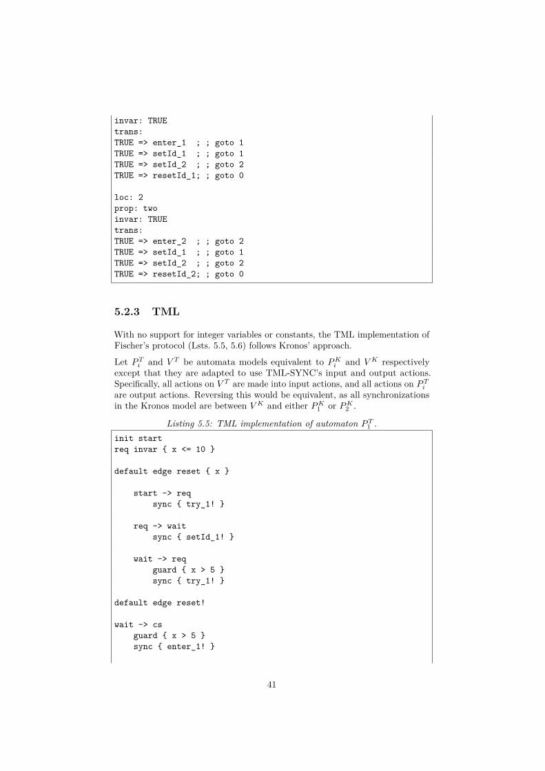
5.2.3 TML
With no support for integer variables or constants, the TML implementation ofFischer’s protocol (Lsts. 5.5, 5.6) follows Kronos’ approach.
Let PTi and V T be automata models equivalent to PK
i and V K respectivelyexcept that they are adapted to use TML-SYNC’s input and output actions.Specifically, all actions on V T are made into input actions, and all actions on PT
i
are output actions. Reversing this would be equivalent, as all synchronizationsin the Kronos model are between V K and either PK
1 or PK2 .
Listing 5.5: TML implementation of automaton PT1 .
init startreq invar { x <= 10 }
default edge reset { x }
start -> reqsync { try_1! }
req -> waitsync { setId_1! }
wait -> reqguard { x > 5 }sync { try_1! }
default edge reset!
wait -> csguard { x > 5 }sync { enter_1! }
41

cs -> startsync { resetId_1! }
Listing 5.6: TML implementation of automaton V T .init zero
zero -> zero sync { try_1? }zero -> zero sync { try_2? }
one -> one sync { enter_1? }two -> two sync { enter_2? }
one -> zero sync { resetId_1? }two -> zero sync { resetId_2? }
[zero, two] -> one -> onesync { setId_1? }
[zero, one] -> two -> twosync { setId_2? }
5.2.4 Assessment
Shared integer variables are used to great effect in the XTA implementation ofthis protocol, replacing the state-keeping automaton necessary in Kronos andTML. The construction used in place of shared integers is quite mechanical andstraightforward, but it constitutes an added complexity which must be handledmanually by the user. Also, quite crucially, it does not scale well with addedprocesses (larger integer variables).
Uppaal’s templates are used to reduce code duplication. In Kronos and TML,additional files not listed but largely identical to the ones given in Lst. 5.3 andLst. 5.5 respectively are needed to produce a second automaton for process p2.
It is not clear however whether any of these two features by itself would benefiteither the Kronos or TML implementation. In the Uppaal model, templates andshared integer variables are used in combination, with template parameter ibeing used to update id.
Furthermore, Uppaal uses integer constants in place of Kronos’s and TML’shard coded values for timing variables k and l. Integer constants are useful forreadability and maintainability, and their value increases in larger systems.
In the TML implementation of Fischer’s protocol, default statements and selectorshorthands are used to save some repetition of properties. In Lst. 5.5, an argumentcould be made that the use of an edge default adds more complexity than what isgained by the absence of repetition, since only applies to three edges. In Lst. 5.6on the other hand, the benefit of edge selector shorthands seems clear – multipleedges are created in a manner which is concise but still readable.
42
5.3 CSMA/CD
Carrier sense, multiple access with collision detection is a protocol for coordinat-ing the transmission of messages between multiple senders in a network over ashared bus. We follow the exact formulation from [28], considering a networkconsisting of two senders s1, s2, and modeling only the sending of messages.
When a station wants to use the bus, it first checks whether the bus is alreadyin use, if so delaying a random duration and trying again. When the bus is free,the station starts transmitting its message.
If both senders detects the bus is free within some short time interval, both maystart transmitting at once, causing a collision. When this race condition occursboth senders will detect the collision and cancel their transmissions, to retry thetransmission procedure after a random duration.
The logic for detecting a collision depends on the worst-case propagation delayσ of the bus network. This is the maximum time it can take for a signal totravel between the outermost nodes of the network, i.e., between s1 and s2 inour simple network [22].
Say that s1 checks the bus and finds it free, then starts transmitting at time t0.In the worst-case, the first bit of s1’s message, indicating that the bus is in use,arrives at s2 at time t0 + σ. Assuming that checking the bus’s state and startingtransmission occurs atomically, s2 may start transmitting at the latest at t0 + σ.There is now a collision, but s2’s signal needs to travel back across the networkfor s1 to notice this. s2’s signal will thus arrive back at s1 at time t0 + 2σ.
After s1 has transmitted for the duration of 2σ without detecting a collision, it isthus guaranteed that no collision will occur and the entire message will be sent.
5.3.1 Kronos
Fig. 5.3 illustrates the CSMA/CD protocol in timed automata form. To capturethe notion of worst-case propagation delay, we use clock x and constant σ. Λis the time it takes to send one complete fixed-size message. In the Kronosimplementation (Lsts. 5.8, 5.7), Λ = 808 and σ = 26 are hard coded.
Both the automata model and its implementation are adapted from [28], withsome minor corrections. Specifically, the guard on edge transm→ retry is changedfrom x < σ to x < 2σ to correct what we believe to be an error, supported by[22] and [21]. Furthermore, three discrepancies between automaton figures andcorresponding Kronos code have been resolved.
43

(a) Automaton SKi representing sender si.
(b) Automaton BK representing the bus.
Figure 5.3: Kronos model of CSMA/CD.
44

Listing 5.7: Kronos implementation of automaton SK1 from Fig. 5.3a.
#locs 3#trans 9#clocks x#sync begin_1 end_1 busy_1 cd_1
loc: 0prop: waitinvar: TRUEtrans:TRUE => begin_1; x := 0; goto 1TRUE => busy_1 ; x := 0; goto 2TRUE => cd_1 ; x := 0; goto 0TRUE => cd_1 ; x := 0; goto 2
loc: 1prop: transminvar: x <= 808trans:x = 808 => end_1; x_1 := 0; goto 0x < 52 => cd_1 ; x_1 := 0; goto 2
loc: 2prop: retryinvar: x <= 52trans:x <= 52 => begin_1; x_1 := 0; goto 1x <= 52 => busy_1 ; x_1 := 0; goto 2x <= 52 => cd_1 ; x_1 := 0; goto 2
Listing 5.8: Kronos implementation of automaton BK from Fig. 5.3b.#locs 3#trans 9#clocks x#sync begin_1 begin_2 end_1 end_2 busy_1 busy_2 cd_1 cd_2
loc: 0prop: idleinvar: TRUEtrans:TRUE => begin_1; x := 0; goto 1TRUE => begin_2; x := 0; goto 1
loc: 1prop: activeinvar: TRUEtrans:x < 26 => begin_1; x := 0; goto 2x < 26 => begin_2; x := 0; goto 2
45

x >= 26 => busy_1 ; ; goto 1x >= 26 => busy_2 ; ; goto 1TRUE => end_1 ; x := 0; goto 0TRUE => end_2 ; x := 0; goto 0
loc: 2prop: collisioninvar: x < 26trans:x < 26 => cd_1 cd_2; ; goto 0
5.3.2 Uppaal XTA
In the Kronos bus automaton BK (Fig. 5.3b), the edge from collision to idle hastwo synchronization actions (cd1, cd2), making both senders synchronize withthe bus at the same instant. In Uppaal, as in TSA, an edge is restricted to onesynchronization action.
For the Uppaal-compatible version BU illustrated in Fig. 5.4b, we solve this byadding an urgent location collision2. This gives an extra edge collision2 → idlewhich is fired simultaneously with collision2’s incoming edge (recall that no timemay pass in an urgent location). Attaching cd2 to this extra edge forces the twosynchronization actions to be performed in the same time instant.
Uppaal’s version of synchronization actions on the other hand allows for somesimplification of the bus model as compared with Kronos. In BK there arefour edge pairs which are essentially duplicates of each other. From idle toactive, for example, there is one edge synchronizing on begin1 and another onbegin2, but which are otherwise identical. In BU , we replace these with a singleedge synchronizing on a common input action begin?, and let each sender SU
i
(Fig. 5.4a) use the corresponding output action begin!. The semantics of inputand output actions ensures that only one sender synchronizes with the bus eachtime begin? is performed. The same simplification is used for synchronizationactions busy and end.
46

(a) Automaton SUi representing sender si in Uppaal.
(b) Automaton BU representing the bus in Uppaal.
Figure 5.4: Uppaal model of CSMA/CD.
47

The Uppaal XTA implementation of CSMA/CD (Lst. 5.9) is based on an oldimplementation made for benchmarking purposes in 2001 [21]. It is one from aset of models with varying numbers of senders, which was generated using anAWK program. As this implementation seems to be based on the earlier Kronosversion from [28], the corrections mentioned in Sec. 5.3.1 carry over to the XTAimplementation presented here.
For this report the model has also been updated to make use of newer Uppaalfeatures in order to better represent the modeling capabilities of Uppaal today.
Template parameters are used to create multiple senders, removing the need forAWK. To make each sender listen for its specific collision detection action, wedefine a global array of channels cd and use the process id (template parameteri) to index into this array.
Another update is the introduction of urgent location collision2. Urgent locationsdid not exist at the writing of the original implementation, so the same idea wasinstead implemented using a location invariant x ≤ 0 on a clock x which was setto 0 on collision2’s incoming edge. This is an equivalent solution, allowing notime to pass in collision2.
Listing 5.9: Uppaal XTA implementation of the CSMA/CD model from Fig. 5.4.chan begin, end, busy;chan cd[2];const int lambda = 808;const int sigma = 26;
typedef int[0,1] id_t;int id;
process Sender(const id_t i) {clock x;
statewait,transm { x <= lambda },retry { x < 2 * sigma };
init wait;
transwait -> transm {
sync begin!;assign x := 0;
},wait -> wait {
sync cd[i]?;assign x := 0;
},wait -> retry {
sync cd[i]?;
48

assign x := 0;},wait -> retry {
sync busy?;assign x := 0;
},transm -> wait {
guard x == lambda;sync end!;assign x := 0;
},transm -> retry {
guard x < 2 * sigma;sync cd[i]?;assign x := 0;
},retry -> transm {
guard x < 2 * sigma;sync begin!;assign x := 0;
},retry -> retry {
guard x < 2 * sigma;sync cd[i]?;assign x := 0;
},retry -> retry {
guard x < 2 * sigma;sync busy?;assign x := 0;
};}
process Bus() {clock x;
stateidle,active,collision_1 { x < sigma },collision_2;
init idle;urgent collision_2;
transidle -> active {
sync begin?;assign x := 0;
},
49

active -> idle {sync end?;assign x := 0;
},active -> active {
guard x >= sigma;sync busy!;
},active -> collision_1 {
guard x < sigma;sync begin?;assign x := 0;
},collision_1 -> collision_2 {
sync cd[0]!;},collision_2 -> idle {
sync cd[1]!;};
}
system Sender, Bus;
Figure 5.5: Automaton BT representing the bus in TML.
50
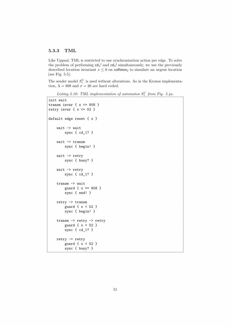
5.3.3 TML
Like Uppaal, TML is restricted to one synchronization action per edge. To solvethe problem of performing cd1! and cd2! simultaneously, we use the previouslydescribed location invariant x ≤ 0 on collision2 to simulate an urgent location(see Fig. 5.5).
The sender model SUi is used without alterations. As in the Kronos implementa-
tion, Λ = 808 and σ = 26 are hard coded.
Listing 5.10: TML implementation of automaton SU1 from Fig. 5.4a.
init waittransm invar { x <= 808 }retry invar { x <= 52 }
default edge reset { x }
wait -> waitsync { cd_1? }
wait -> transmsync { begin! }
wait -> retrysync { busy? }
wait -> retrysync { cd_1? }
transm -> waitguard { x == 808 }sync { end! }
retry -> transmguard { x < 52 }sync { begin! }
transm -> retry -> retryguard { x < 52 }sync { cd_1? }
retry -> retryguard { x < 52 }sync { busy? }
51
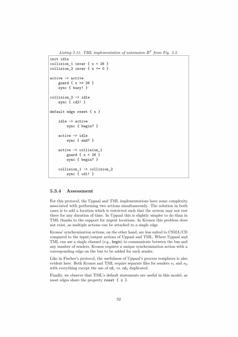
Listing 5.11: TML implementation of automaton BT from Fig. 5.5.init idlecollision_1 invar { x < 26 }collision_2 invar { x <= 0 }
active -> activeguard { x >= 26 }sync { busy! }
collision_2 -> idlesync { cd2! }
default edge reset { x }
idle -> activesync { begin? }
active -> idlesync { end? }
active -> collision_1guard { x < 26 }sync { begin? }
collision_1 -> collision_2sync { cd1! }
5.3.4 Assessment
For this protocol, the Uppaal and TML implementations have some complexityassociated with performing two actions simultaneously. The solution in bothcases is to add a location which is restricted such that the system may not restthere for any duration of time. In Uppaal this is slightly simpler to do than inTML thanks to the support for urgent locations. In Kronos this problem doesnot exist, as multiple actions can be attached to a single edge.
Kronos’ synchronization actions, on the other hand, are less suited to CSMA/CDcompared to the input/output actions of Uppaal and TML. Where Uppaal andTML can use a single channel (e.g., begin) to communicate between the bus andany number of senders, Kronos requires a unique synchronization action with acorresponding edge on the bus to be added for each sender.
Like in Fischer’s protocol, the usefulness of Uppaal’s process templates is alsoevident here. Both Kronos and TML require separate files for senders s1 and s2,with everything except the use of cd1 vs. cd2 duplicated.
Finally, we observe that TML’s default statements are useful in this model, asmost edges share the property reset { x }.
52
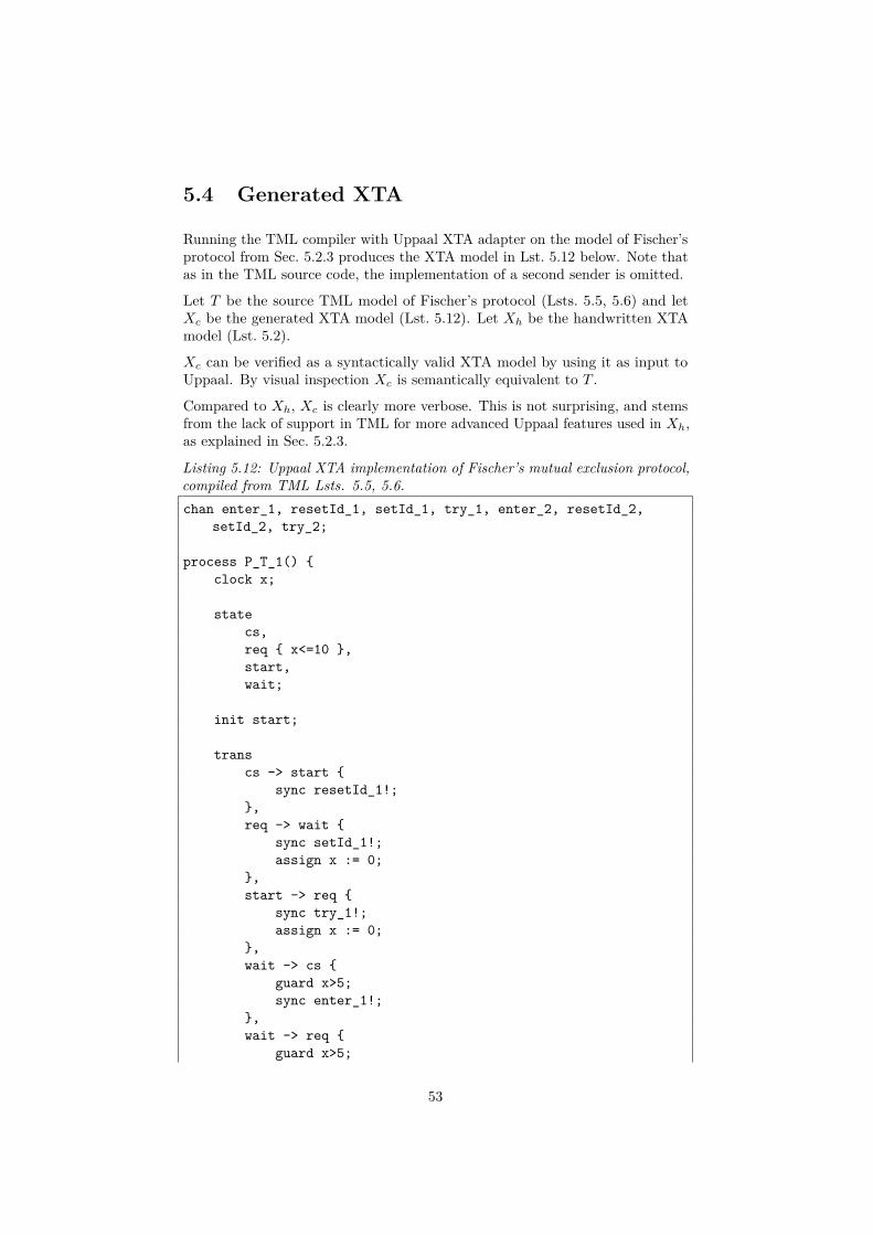
5.4 Generated XTA
Running the TML compiler with Uppaal XTA adapter on the model of Fischer’sprotocol from Sec. 5.2.3 produces the XTA model in Lst. 5.12 below. Note thatas in the TML source code, the implementation of a second sender is omitted.
Let T be the source TML model of Fischer’s protocol (Lsts. 5.5, 5.6) and letXc be the generated XTA model (Lst. 5.12). Let Xh be the handwritten XTAmodel (Lst. 5.2).
Xc can be verified as a syntactically valid XTA model by using it as input toUppaal. By visual inspection Xc is semantically equivalent to T .
Compared to Xh, Xc is clearly more verbose. This is not surprising, and stemsfrom the lack of support in TML for more advanced Uppaal features used in Xh,as explained in Sec. 5.2.3.
Listing 5.12: Uppaal XTA implementation of Fischer’s mutual exclusion protocol,compiled from TML Lsts. 5.5, 5.6.chan enter_1, resetId_1, setId_1, try_1, enter_2, resetId_2,
setId_2, try_2;
process P_T_1() {clock x;
statecs,req { x<=10 },start,wait;
init start;
transcs -> start {
sync resetId_1!;},req -> wait {
sync setId_1!;assign x := 0;
},start -> req {
sync try_1!;assign x := 0;
},wait -> cs {
guard x>5;sync enter_1!;
},wait -> req {
guard x>5;
53

sync try_1!;assign x := 0;
};}
process V_T() {state
one,two,zero;
init zero;
transone -> one {
sync enter_1?;},one -> one {
sync setId_1?;},one -> two {
sync setId_2?;},one -> zero {
sync resetId_1?;},two -> one {
sync setId_1?;},two -> two {
sync enter_2?;},two -> two {
sync setId_2?;},two -> zero {
sync resetId_2?;},zero -> one {
sync setId_1?;},zero -> two {
sync setId_2?;},zero -> zero {
sync try_1?;},zero -> zero {
sync try_2?;};
54

}
system P_T_1, V_T;
5.5 Summary
In this chapter, we compared implementations of Fischer’s protocol andCSMA/CD in Uppaal XTA, Kronos, and TML.
Uppaal’s automaton templates were found to be useful in both systems, asboth are modeled using a number of nearly identical automata. For Fischer’sprotocol, Uppaal’s shared integer variables were further found to simplify theimplementation significantly.
In the CSMA/CD model, Kronos’s ability to attach several actions to a singleedge was found useful. The Kronos model of synchronization actions was foundto be less flexible than that of Uppaal and TML in the modeling of one-to-manycommunication.
TML’s default statements and selector shorthands were used in both models.Both features are used to produce multiple edges or locations with some sharedproperty.
Finally, by presentation of a compiled model of Fischer’s protocol, TML is shownto be usable as an input method for Uppaal. Compared to the correspondinghandwritten Uppaal model, the compiled model is more complex. This is due tothe lack of support in TML for many Uppaal features.
55

Chapter 6
Discussion
From the evaluation, it is clear that Uppaal XTA supports a great number ofuseful features not present in either Kronos or TML.
The XTA implementations of Fischer’s protocol and CSMA/CD both make useof parameterized templates to create multiple versions of the same process type,e.g., senders in CSMA/CD. Writing multiple such versions manually is time-consuming and makes editing very cumbersome as it results in large amounts ofduplicated code.
In addition, shared integer variables seem to be critical for implementing Fischer’sprotocol in any concise manner.
Shared variables and templates are particularly useful in combination. InFischer’s protocol, for example, we use template parameters to provide eachgenerated automaton process with a process identifier which is used to updatea shared variable id. In the CSMA/CD implementation, a process identifier isused to index into a shared array of synchronization channels.
The main contributions of TML in terms of language features are default state-ments and selector shorthands (edge chains and location groups). Both areadapted from Graphviz Dot, with the addition of allowing location groups to beused as selectors in location statements. From the evaluation results, both thesefeatures appear useful in a timed automata modeling context.
Edge chains and location groups offer methods for grouping related edges orlocations, in a manner which makes the code more concise. Use of such groupingscould also improve readability, as they may help convey a better idea of themodel’s structure.
Like selector shorthands, default statements target groups of edges or locationsrelated via a set of shared properties with the goal of reducing code duplication.From the evaluation, we find that the readability argument for default statementsis not as strong as for selector shorthands. This is primarily due to the factthat the distance between a default statement and an element it applies to maybe arbitrarily large. This could make it difficult to immediately discern whichdefaults apply to a given element. The problem can be mitigated somewhat
56
through the use of indentation, as is done in the evaluation (e.g., Lst. 5.5).Nevertheless, default statements seem at least capable of producing hard-to-readcode if not used sensibly, which is a negative.
Finally, the loose requirements that TML places on declarations also affectreadability. In particular, locations do not need to be explicitly declared beforetheir use in edge selectors. A location declaration is usually added only incombination with an associated init or invar keyword, i.e., when the declarationitself adds semantic information. Clocks cannot be explicitly declared at all, asin the TSA model all clocks are initialized to zero at the start of an automatonrun.
The general design principle behind these decisions was to make the language asconcise as possible, i.e., to avoid forcing the user to write any code which is notstrictly needed. Of course, the value of a modeling language does not correlatedirectly to the number of words required to implement a given model. In thiscase, one can discuss whether it would have been wiser to follow the conventionof requiring variables to be declared before they are referenced, which is used inKronos and Uppaal as well as in most general purpose programming languages.
57

Chapter 7
Conclusion andFuture Work
In this chapter, we conclude the thesis by relating our main results to the originalresearch questions, and giving some ideas for further development of TML.
7.1 Conclusion
This thesis proposes the language TML as a tool for constructing timed automatamodels.
From a comparative evaluation of TML against Kronos and Uppaal, Uppaal isconsidered the most complete due to its well developed feature set. However,TML contributes some new language features which lack direct counterparts inKronos and Uppaal. Specifically, TML introduces default statements and edgeselector shorthands. Both these features are adapted from the general graphmodeling language Dot. Through this work, they are shown to be useful in atimed automata modeling context. Consequently, TML is considered to achievesome improvement over the modeling languages of Kronos and Uppaal.
The design of TML is primarily guided by its intended use as an interface forthe m2mc system. Though the connection between TML and m2mc is notcompletely established in this work, it is expected that TML will fit m2mc well.Future development of m2mc may require additions to TML’s syntax, thoughmodification of existing TML features should not be necessary.
An additional contribution of this work is a compiler for TML, implementedusing the Miking metalanguage system. This was originally intended to answera secondary research question about the usability of Miking for compiler con-struction. However, we ultimately consider this work insufficient for providingan accurate evaluation of Miking.
58

7.2 Future Work
Coupled with the XTA adapter, TML is shown to be usable beyond its intendedpurpose of integration with m2mc. However, its practical usability for construc-tion of Uppaal models is limited by the large number of Uppaal features notsupported in TML. Further development of the TML compiler in this directioncould make TML useful as an alternative Uppaal front end.
Aside from the addition of Uppaal features, many of which could be portedmore or less directly to TML, we will mention two ideas for improvement of thecurrent compiler implementation.
7.2.1 Disconnected Chains in Edge Selectors
A current restriction on edge selectors is that all locations or location groups areconnected in a continuous chain. It makes sense to extend edge selectors so thatthey can be composed of multiple disconnected chains:
[a, b] -> c -> d, e -> f
This extension would bring greater parity with location statements, which placesno structural requirements on the set of locations used in a selector.
7.2.2 Default Blocks
TML could also benefit from the implementation of some version of Dot’ssubgraphs (Sec. 3.1.1), used to limit the scope of default statements.
As the similarities with Graphviz Dot increase in number, one might also considerthe alternative of using Dot directly as the input language for a timed automatasystem. The generality of its syntax allows for attachment of a named stringor integer value to any location or edge, which could be used to representtimed automaton properties like location invariants and edge guards. This isexemplified in Sec. 3.1, Lsts. 3.1, 3.2.
59
Bibliography
[1] Alur, R., Courcoubetis, C. and Dill, D. 1990. Model-checking for real-timesystems. Proceedings of the fifth annual IEEE symposium on logic incomputer science. IEEE. 414–425.
[2] Alur, R. and Dill, D.L. 1994. A theory of timed automata. Theoreticalcomputer science. Elsevier. 126, 2. 183–235.
[3] Behrmann, G., David, A. and Larsen, K.G. 2004. A tutorial on Uppaal.Formal methods for the design of real-time systems: Fourth internationalschool on formal methods for the design of computer, communication, andsoftware systems. Springer. 200–236.
[4] Behrmann, G., David, A. and Larsen, K.G. A tutorial on Uppaal4.0: https://www.it.uu.se/research/group/darts/papers/texts/new-tutorial.pdf . Accessed: 2020-09-21. Revised and extended version of [3].
[5] Bengtsson, J. and Yi, W. 2003. Timed automata: Semantics, algorithmsand tools. Advanced course on petri nets. Springer. 87–124.
[6] Bouyer, P. et al. 2018. Model checking real-time systems. Handbook ofmodel checking. Springer. 1001–1046.
[7] Boyd, S.P. Lecture notes on feedback control systems: https:// stanford.edu/~boyd/ee102/ctrl-static.pdf . Accessed: 2021-01-05.
[8] Broman, D. 2019. A vision of Miking: Interactive programmatic modeling,sound language composition, and self-learning compilation. Proceedingsof the 12th ACM SIGPLAN international conference on software languageengineering. ACM. 55–60.
[9] Broman, D. High-confidence formal verification of real cyber-physicalsystems: From models to machine code: https://people.kth.se/~dbro/projects.html. Accessed: 2020-09-14.
[10] Cascading style sheets: https://www.w3 .org/Style/CSS . Accessed: 2021-01-02.
[11] Daws, C. et al. 1995. The tool Kronos. Lecture notes in computer science:Hybrid systems III, verification and control. Springer. 208–219.
60

[12] Extensible markup language (XML) 1.0 (fifth edition): Notation: https://www.w3 .org/TR/REC-xml/#sec-notation. Accessed: 2021-01-22.
[13] Graphviz: https://graphviz.org. Accessed: 2021-01-02.
[14] Graphviz: The Dot language: https://graphviz.org/doc/inf o/ lang.html.Accessed: 2020-09-30.
[15] Henzinger, T.A. et al. 1994. Symbolic model checking for real-timesystems. Cornell University.
[16] Jard, C. and Roux, O.H. 2009. Communicating embedded systems. Wiley.
[17] Kronos: http://www-verimag.imag.f r/DIST-TOOLS/TEMPO/kronos. Accessed: 2020-10-28.
[18] Lamport, L. 1987. A fast mutual exclusion algorithm. ACM Transactionson Computer Systems. ACM. 5, 1. 1–11.
[19] Menghi, C. et al. 2020. Model checking MITL formulae on timedautomata: A logic-based approach. ACM Transactions on ComputationalLogic. ACM. 21, 3. 1–44.
[20] Miking: README: https://github.com/miking-lang/miking/blob/develop/README.md. Accessed: 2020-12-08.
[21] Moeller, M.O. 2001. Uppaal CSMA/CD model: https://www.it.uu.se/research/group/darts/uppaal/benchmarks/csma/csma_input_02.ta.Accessed: 2020-12-11.
[22] Nutt, G. and Bayer, D. 1982. Performance of CSMA/CD networks undercombined voice and data loads. IEEE Transactions on Communications.IEEE. 30, 1. 6–11.
[23] Pombrio, J. and Krishnamurthi, S. 2014. Resugaring: Lifting evaluationsequences through syntactic sugar. Proceedings of the 35th ACM SIG-PLAN conference on programming language design and implementation.ACM. 361–371.
[24] Uppaal: http://www.uppaal.org. Accessed: 2020-09-30.
[25] Uppaal 4.1.24 for 64-bit macOS: http://uppaal.org/download/ . Accessed:2020-12-02.
[26] Uppaal Tiga: https://people.cs.aau.dk/~adavid/tiga/ . Accessed: 2020-10-27.
[27] Waez, M.T.B., Dingel, J. and Rudie, K. 2013. A survey of timed automatafor the development of real-time systems. Computer Science Review.Elsevier. 9. 1–26.
61

[28] Yovine, S. 1997. Kronos: A verification tool for real-time systems. Inter-national Journal on Software Tools for Technology Transfer. Springer. 1,1-2. 123–133.
62

Appendix A
IntermediateRepresentation
This appendix details the intermediate JSON representation of each TML variant.The IR for TML-TSA is presented first, after which follows modifications usedfor the other language variants. For details on the JSON format, see https://www.json.org.
TML-TSA
Table A.1: Root object
Property Type Description
actions Array of strings All actions used in the program.clocks Array of strings All clocks used in the program.locations Array of Location objects Automaton locations.edges Array of Edge objects Automaton edges.
Table A.2: Location object
Property Type Description
id String Location identifier.initial Boolean True for the initial location, false for all others.invariant Null or string Location invariant (optional).
63

Table A.3: Edge object
Property Type Description
from String Identifier of source location.to String Identifier of target location.guard Null or string Guard expression (optional).reset Null or array of strings Set of clocks to reset (optional).action Null or string Edge action identifier (optional).
TML-SYNC
In this variant, the property action on Edge objects is replaced with an optionalproperty sync of type Action object described below. On the root object, theproperty actions is renamed channels.
Table A.4: Action object
Property Type Description
id String Action identifier.type String input or output.
TML-CTRL
This variant adds a Boolean property controllable to the Edge object. Other-wise the format is identical to that of TML-TSA.
TML-CTRL-SYNC
This variant uses TML-TSA’s IR format with the modifications from bothTML-SYNC and TML-CTRL.
64

TRITA-EECS-EX-2021:58
www.kth.se