Embed Size (px)
Citation preview

International Journal of Electrical Engineering. ISSN 0974-2158 Volume 8, Number 3 (2015), pp. 239-251
© International Research Publication House
http://www.irphouse.com
A Modified Control Method For A Dual Unified
Power Quality Conditioner
K. Harinath Reddy1
Assistant Professor Dept. Of EEE/A. I. T. S
B. Murali Mohan2
Assistant Professor Dept. Of EEE/A. I. T. S Kadapa 516001, A. P., INDIA. muralimohanaits1@gmail. com
V. Aruneswari3
PG Scholar Dept. Of EEE/A. I. T. S
Abstract
This paper presents a modified control method for a dual three phase unified power
quality conditioner (iUPQC). The iUPQC consists of two active filters. One is series active filters (SAF) and another one is parallel active filter (PAF). The SAF is used
for voltage sag/swell compensation and PAF is used to eliminate current harmonics
and unbalances. The two active filters are controlled by using sinusoidal references
but in conventional UPQC two active filters are controlled by using non sinusoidal references. Therefore the iUPQC uses PWM and fuzzy logic control technologies.
Fuzzy logic controller is based on fuzzy sets and fuzzy rules with their membership
functions of inputs and outputs.
Key words: Active Filters, iUPQC, voltage interruption, Fuzzy logic control.
I. Introduction With the invention of power electronic devices like thyristors, GTO`s (Gate Turn Off
Thyristors) and many devices, control of electric power is simple and easy. But the
power electronic devices have their non linearity characteristics, cause harmonic and
draw excessive currents. The harmonics, excessive currents cause for low system efficiency. In addition to this power system is subjected to various disturbances like
voltage sags and swells etc.

240 K. Harinath Reddy et al
By using Unified power Quality Conditioner (UPQC) [1]-[10] it can supply regulated voltage for the loads, balanced and low harmonic distortion. The UPQC consists of
series and shunt active power filters. Shunt active filters also provides harmonic
isolation between supply system and load. The series active filter regulates the incoming voltage quality.
In the conventional UPQC both series active filters and shunt active filters are
controlled by using non sinusoidal references. PAF usually acts as non sinusoidal
current source used to reduce harmonic currents of the load. SAF acts non sinusoidal voltage source used to mitigate voltage disturbances. Non sinusoidal references mean
combination of both fundamental and harmonic references. The extraction of
harmonic contents requires complex calculations. Therefore there are so many
methods to extract harmonics, but it is more complexity of reference generation [10]. Some works gives control methods for both series and shunt active filters for
generation of sinusoidal references without need of harmonic extraction, in order to
decrease the complexity of the reference generation for the UPQC.
This conditioner consists of two voltage source convertors. In order to generate sinusoidal reference SAF consists of three current loops and two voltage loops. PAF
consists of three voltage loops. In this way both grid current and load voltage are
sinusoidal and therefore their references are also sinusoidal.
The main purpose of this paper is to propose a modified control method for a dual three phase topology of a Unified Power Quality Conditioner (iupqc) [5] used in
utility grid connection. ABC reference frame, classical control theory is used in this
control method.
II. Dual Unified Power Quality Conditioner Combined series and shunt active filters are known as unified power quality
conditioner. These are designed to compensate voltage disturbances and to reduce current harmonics. In conventional UPQC the series active filter used as voltage
source that compensates voltage interruption, sag and swell. The parallel active filer
used as current source which compensates load current. Series active filter is
connected in series to the line through a transformer while parallel active filter is directly connected to the load as shown in fig1.
The draw backs of unified power quality conditioner are
- More complex current and voltage reference generation. - The leakage impedance of the transformer affects the injected voltage.
- complex calculations are required in order to extract harmonics.
To reduce the above draw backs a modified control method is used for Unified Power Quality Conditioner. The conventional UPQC is same as dual Unified Power Quality
conditioner the only difference is way of controlled. The main aim of series active
filter is to synchronise the current with grid voltage. The aim parallel active filter is to
synchronise the load voltage with grid voltage. In this way the iUPQC [5] uses sinusoidal references for filters.
A Modified Control Method For A Dual Unified Power Quality Conditioner 241
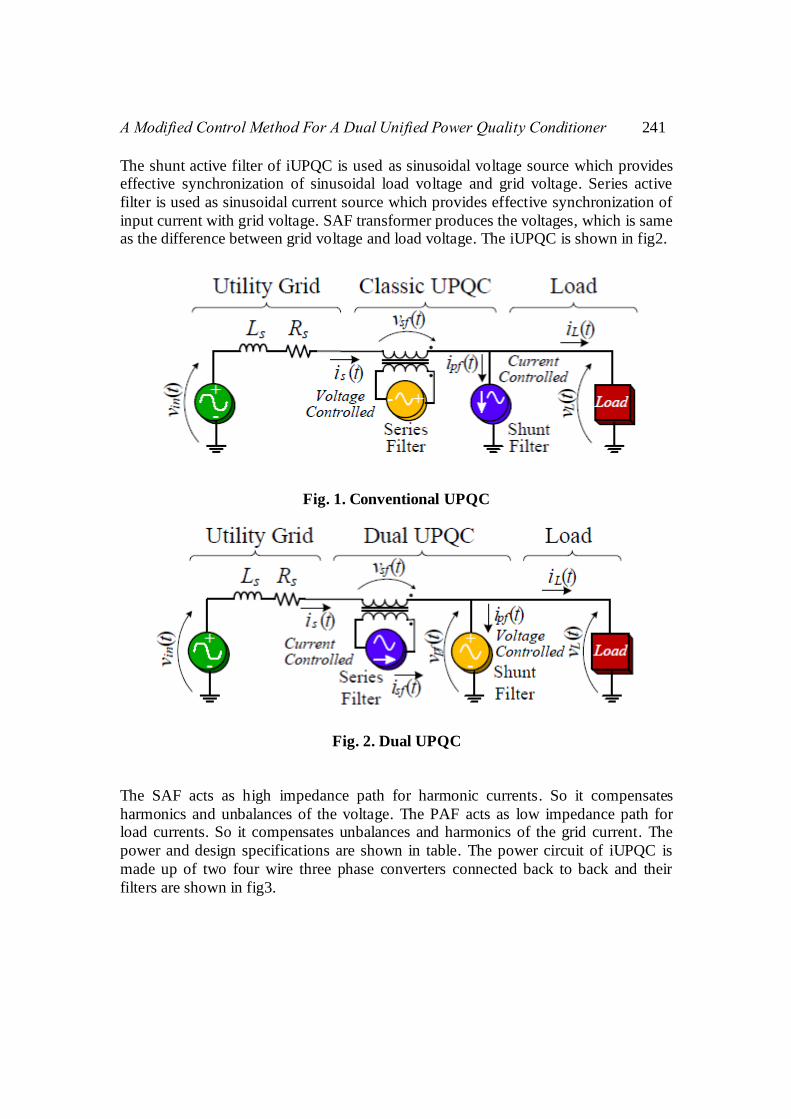
The shunt active filter of iUPQC is used as sinusoidal voltage source which provides effective synchronization of sinusoidal load voltage and grid voltage. Series active
filter is used as sinusoidal current source which provides effective synchronization of
input current with grid voltage. SAF transformer produces the voltages, which is same as the difference between grid voltage and load voltage. The iUPQC is shown in fig2.
Fig. 1. Conventional UPQC
Fig. 2. Dual UPQC
The SAF acts as high impedance path for harmonic currents. So it compensates
harmonics and unbalances of the voltage. The PAF acts as low impedance path for load currents. So it compensates unbalances and harmonics of the grid current. The
power and design specifications are shown in table. The power circuit of iUPQC is
made up of two four wire three phase converters connected back to back and their
filters are shown in fig3.

242 K. Harinath Reddy et al
TABLE I Design Specifications of the iUPQC
Input line to line Voltage
Output nominal power
DC link voltage
Utility grid frequency
Switching frequency of series and PAFs
Transformer ratio n=1
TABLE II Specifications of the power modules
Leakage inductance of the SAF coupling transformers
Transformer ratio of the SAF coupling Transformers n=1
SAF connection inductance
PAF connection inductance
DC Link Capacitance
In SAF in three phases three single phase transformers are used. The parallel active
filters are directly connected to the load.
III. Control Methods
The iUPQC mainly consists of series and parallel active filer controllers. The series active filter has current loop in order to deliver a sinusoidal grid current and
synchronised with grid voltage. The parallel filter consist voltage loop in order to
allow a synchronised, regulated voltage to the load. These control loops are working
independently in each filter. The series active filter has two another voltage loops in order to control the dc link voltage. Here voltage loop determines the current
amplitude reference for the current loop.
Therefore series active filter control uses an input current and DC link voltage
feedback. The parallel active filter control uses voltage feedback. The sinusoidal references are generated by using digital signal processor (DSP). The
synchronisation of input current and grid voltage are obtained through Phase Locked
Loop (PLL). The control structure is in ABC reference frame. Since the power
calculation and harmonic extraction are not needed.
1. SAF CONTROL The control block diagram of the SAF is shown in fig 3. This consists of three
identical current loops and two voltage loops. Each current loop is to control the input current. One voltage loop is to control DC link voltage and another voltage loop is to
keep the voltage on the DC link capacitors balanced.

A Modified Control Method For A Dual Unified Power Quality Conditioner 243
Fig. 3. Control block diagram of SAF
The amplitude current reference for current controller is determined from the voltage
control loop, because the voltage control loop has low frequency response. When load
increases the controllers will supply the additional power. So the active power
consumption from dc storage. This makes dc link voltage imbalance. The voltage unbalanced loop generates the average dc reference voltage and maintain the two
capacitor voltage equal.
Fig. 4: Single Phase equivalent circuit of SAF.
To control the dc link voltage fuzzy logic and pole controllers are used. All the controls have phase margin between 30o and 90o. The current control consists of three
identical loops, except for 120o phase displacement from each other. When voltage
imbalance occur the unbalanced voltage control loop changes current reference, to
equalise the capacitor voltages.

244 K. Harinath Reddy et al
The voltage loop transfer function is represented as
The Unbalance Voltage loop transfer function is represented as
The Current loop transfer function is represented as
Where
Cb -DC Link Capacitance;
Hdsf -Unbalance Voltage Sensor Gain;
Hisf -Current Sensor Gain; HVsf -Voltage Sensor Gain;
Kdsf -Unbalance Voltage Control attenuation;
Kisf -Current Control Attenuation;
KVsf -Voltage Control Attenuation; Km -Multiplier Gain;
Lsf -Series Filter Inductance;
ma -Modulation Ratio;
Vb -DC Link Voltage; Vmsf - Pulse Width Modulator Gain.
Fig. 4: Voltage loop frequency response of the SAF.

A Modified Control Method For A Dual Unified Power Quality Conditioner 245
Fig. 5: Unbalance Voltage loop frequency response of SAF.
Fig. 6: Current loop frequency response of the SAF.
2. PAF CONTROL The Parallel active filter scheme consists of three identical voltage feedback loops.
Each loop is used for each phase, in order to compare the load voltage signal and
sinusoidal reference. These loops are except for 120 degree phase displacements from
references of each other. Fig. 7 shows the control block diagram of the parallel active filter.

246 K. Harinath Reddy et al
The voltage loop transfer function is obtained by the analysis of single phase equivalent circuit shown in fig. 8. For circuit analysis average values related to
switching period are used. By using small signal analysis and Laplace the voltage
loop transfer function is given by
Fig. 7: Control block diagram of the PAF.
Fig. 8: Single phase equivalent circuit of PAF
The open loop transfer function is given by

A Modified Control Method For A Dual Unified Power Quality Conditioner 247
Fig. 9: Voltage loop frequency response of the PAF.
Kpwmpf - Shunt filter PWM modulator gain
The voltage loop frequency response is shown in fig. 9, including the open loop
transfer function, controller transfer function and the compensated loop transfer function.
3. FUZZY LOGIC CONTROL The Fuzzy logic control consists of set of linguistic variables. The mathematical
modelling is not required in FLC. FLC [9] consists of
1. Fuzzification Membership function values are assigned to linguistic variables. In this the scaling
factor is between 1 and -1.
2. Inference Method There are several composition methods such as Max-Min and Max-Dot have been
proposed and Min method is used.
3. Defuzzificaion A plant requires non fuzzy values to control, so defuzzification is used. The output of
FLC controls the switch in the inverter. To control these parameters they are sensed
and compared with the reference values. To obtain this the membership functions of
fuzzy controller are shown in fig (10).

248 K. Harinath Reddy et al
Fig. 10: Fuzzy logic Controller
IV. Power Flow
The active power flow of the iUPQC is shown in fig. 10. In fig. 10(a) the grid voltage
Vs has lower amplitude than the load voltage VL. So the PAF delivers active power to
the load. In fig. 10(b) the grid voltage Vs has higher amplitude than the load voltage VL. In this case SAF delivers active power to the load. Therefore voltage imbalance
occurs at the dc link. This voltage imbalance can be compensated by unbalance
voltage loop transfer function. When Vs is equal to VL the power drained from the
electrical grid equals the sum of the load power and the iUPQC power losses.
Fig. 10: Power flow of iUPQC; (a) Vs<VL (b) Vs>VL

A Modified Control Method For A Dual Unified Power Quality Conditioner 249
V. Simulation Results The simulation results of the Dual Unified Power Quality Conditioner using fuzzy
logic controller are shown in fig. 11. Here we are creating voltage dip and load
changing. Therefore the voltage unbalance and harmonics are controlled by using series active filter, parallel active filter and fuzzy logic controllers. The injected
voltage to compensate the voltage can be suppled by using DC Link voltage.
Fig. 11 (a):Source voltage and load voltage during a voltage dip in phase in A
Fig. 11(b): Load voltages and source currents
Fig. 11(c): Parallel active filter currents

250 K. Harinath Reddy et al
Fig. 11(d): Series active filter voltages
Fig. 11(e): Load voltages and load currents during load change
Fig. 11(f): DC link voltage and load current

A Modified Control Method For A Dual Unified Power Quality Conditioner 251
VII. Conclusion The results obtained with iUPQC using fuzzy logic controller and ABC reference
frame were able to compensate the non linear load currents and also to provide the
sinusoidal load voltages. The main advantage of the proposed scheme is to provide sinusoidal references which reduce complexity of harmonic extraction.
The proposed scheme of iUPQC using fuzzy logic controller in ABC reference frame
of both SAF and PAF control loops are generated by a digital signal processor. This
control loops and its utilisation of sinusoidal references eliminates the harmonics between grid and load. The results show the proposed iUPQC control scheme
providing power quality improvement.
REFERENCES
[1] V. Khadkikar and A. Chandra, “A noval structure forthree-phase fourwire
distribution system utilizing unified power quality conditioner (upqc), ” IEEE
Trans. on Ind. Appl., vol. 45, no. 5, pp. 1897–1902, Sept 2009. [2] B. Han, B. Bae, S. Baek, and G. Jang, “New configuration of upqc for
medium-voltage application, ” IEEE Trans. on Power Deliv., vol. 21, no. 3,
pp. 1438–1444, July 2006.
[3] A. Jindal, A. Ghosh, and A. Joshi, “Interline unified power quality conditioner, ” IEEE Trans. on Power Deliv., vol. 22, no. 1, pp. 364–372, Jan
2007.
[4] M. Basu, S. Das, and G. Dubey, “Investigation on the performance of upqc-q
for voltage sag mitigation and power quality improvement at a critical load point, ” IET Generation Transmission Distribution, vol. 2, no. 3, pp. 414–423,
May 2008.
[5] M. Aredes and R. Fernandes, “A dual topology of unified power quality
conditioner: The iupqc, ” in 13th European Conf. on Power Electron. And Appl., Sept 2009, pp. 1–10.
[6] F. Kamran and T. Habetler, “A novel on-line ups with universal filtering
capabilities, ” IEEE Trans. on Power Electron., vol. 13, no. 3, pp. 410– 418,
May 1998. [7] K. Karanki, G. Geddada, M. Mishra, and B. Kumar, “A modified three phase
four-wire upqc topology with reduced dc-link voltage rating, ” IEEE Trans. on
Ind. Electron., vol. 60, no. 9, pp. 3555–3566, Sept 2013.
[8] Hamid Reza Mohammadi, Ali Yazdian Varjani, and Mokhtari, “Multiconverter Unified Power-Quality Conditioning System: MCUPQC”
IEEE TRANSACTIONS ON POWER DELIVERY, VOL. 24, NO. 3, JULY
2009.
[9] Surya kalavathi, Vasishta kumar and Zabi, “Fuzzy based interline power quality conditioner for power enhancement” IEEE Transactions on
International journal of research in electrical. vol. 4 April 2015.
[10] M. Kesler and E. Ozdemir, “Synchronous-reference-frame-based control
method for upqc under unbalanced and distorted load conditions, ” IEEE Trans. on Ind. Electron., vol. 58, no. 9, pp. 3967–3975, Sept 2011

252 K. Harinath Reddy et al